
MagicSpeed MS700 - Cruise control WAECO - Free user manual and instructions
Find the device manual for free MagicSpeed MS700 WAECO in PDF.

| Product type | Automatic cruise control |
| Brand | WAECO |
| Model | MagicSpeed MS700 |
| Operating voltage | 12 V |
| Max. current consumption | 10.5 A |
| Operating temperature | -40°C to +85°C |
| Useful travel of Bowden cable | 38 mm or 45 mm (adjustable) |
| Main functions | SET (speed memorization), RES (resume memorized speed), ON/OFF, acceleration/deceleration in steps of 1.5 km/h |
| Diagnostic modes | A (components and connections), B (servomechanism), C (speed/engine speed signal) |
| Adjustment modes | PPM (input signal), INIT (resume sensitivity), GAIN (regulation sensitivity) |
| Minimum operating speed | Approx. 40 km/h |
| Speed increment | Approx. 1.5 km/h per pulse |
| Safety devices | Cut-off on brake, clutch, overspeed (>150% or <50% of set value), ignition cut-off, brake light fault |
| Power supply | Orange wire on terminal 15 (12 V after ignition) |
| Speed signal | Blue wire (1.5-24 V, 6 Hz-8.5 kHz) |
| Engine speed signal | Yellow wire (6-250 V, 6 Hz-488 Hz) |
| Installation | Electronic module in passenger compartment, servomechanism in engine compartment |
| ABE No. | 90669 |
| Optional accessories | Magnetic detector kit (AS71430), Speed pulse generator (MS-AA-144) |
| Kit contents | Electronic module, servomechanism, wiring harness, mounting kit, control module |
| Maintenance | Regularly check connections and condition of Bowden cable |
| Safety | Disconnect battery before electrical work; do not use on slippery roads |
| Spare parts | Available through WAECO after-sales service |
| Languages of manual | French, German, English, Spanish, Finnish, Italian, Dutch, Norwegian, Swedish, Danish |
| Pages | 296 |
Frequently Asked Questions - MagicSpeed MS700 WAECO
User questions about MagicSpeed MS700 WAECO
0 question about this device. Answer the ones you know or ask your own.
Ask a new question about this device
Download the instructions for your Cruise control in PDF format for free! Find your manual MagicSpeed MS700 - WAECO and take your electronic device back in hand. On this page are published all the documents necessary for the use of your device. MagicSpeed MS700 by WAECO.
USER MANUAL MagicSpeed MS700 WAECO
Installation and Operating Manual
Read these operating instructions before installing the attachment.
List of contents
Illustrations for the installation instruction 3-12
List of contents 41
Information for using the installation instructions. 41
Safety and installation instructions 42
Scope of delivery 44
Required tools 45
Command module 45
Variable throttle lever - stroke 45
Cable - changing stroke 46
Fitting the throttle lever 46
Electronics module. 47
Cable harness 47
Diagnostic mode 53
Safety devices 55
Adjustment/training mode 56
Operation of the cruise control 61
Function test 62
Troubleshooting 63
Accessories 65
Adjustment mode 67
Disposal instructions 68
Technical data 68
Information for using the installation instructions

Warning! Safety instruction:
Failure in observing these warnings may result in injuries to persons or damage to material.

Caution! Safety precaution:
Failure in observing these warnings may result in damage to material and improper functioning of the cruise control MS-700.

The rhombus marks installation steps which you have to implement.
To ensure problem-free fitting, read these installation and operating instructions carefully before starting work. If the operating instructions do not answer all your questions, or if the assembly steps are not clear, please do not hesitate to contact our customer technical support service.
Safety and installation instructions

Warning! Inadequate cable connections can lead to short-circuits which cause the following:
- cable fires
- triggering of the airbag
- damage to electronic control equipment
- failure of electrical functions (blinkers, brake-lights, horn, ignition, lights).

Please note the following:
When working on the cabling of the vehicle, the following terminal designations apply:
30 (input of battery plus direct),
15 (switched plus, behind battery)
31 (recirculation from battery, mass)
58 (parking light) (back-up light)
The securest form of connection is obtained by soldering the cable ends and then insulating the connection.
For detachable connections, only insulated cable lugs, connector plugs, and flat pin bushings must be used. Do not use insulating screw joints.
Use crimping pliers to connecting the cables with cable lugs, plugs or flat pin bushings.
With cable connections to 31 (mass):
Screw the cable with cable lug and toothed lock washer to a vehicle-specific mass bolt or screw it with a cable lug, self-tapping screw and toothed lock washer to the car's bodywork.
Always ensure that the connection is properly earthed!

Warning! Due to the risk of short-circuits, always disconnect the negative terminal of the battery before starting to work on the electrical equipment of the vehicle.
If the vehicle is equipped with a supplementary battery, also disconnect its negative terminal.
Caution! When disconnecting the negative terminal of the battery, all volatile memories of the comfort-electronics lose their stored data.
Safety and installation instructions
Depending on the vehicle's equipment, the following date may need to be reprogrammed: Radio-code · vehicle clock · timeswitch clock · onboard computer · seat position
Instructions on how to reset these can be found in the relevant operating instructions.

Caution! Only a voltmeter may be used to check the voltage in electrical cables (see B 2).

Caution! To avoid damage, always ensure that there is enough space for the drill bit to emerge. Every drill hole must be deburred and treated with a rustproofing agent.
Caution! When installing the electrical connections, ensure they are not sharply bent and twisted,
- do not rub at the edges,
- are not inserted through sharp-edged openings.

Caution! Ensure that it is not necessary for the driver to insert his hand through the steering wheel and that the MagicSpeed components are not within the deployment area of the vehicle's airbag and the head impact range.
WAECO International does not accept any liability for damages due to the following:
a) incorrect assembly
b) damage to the system by mechanical effects and overvoltages
c) modifications to MagicSpeed without the explicit approval of WAECO International
d) use for any purposes other than those described in the assembly instructions.
Scope of delivery
Article Parts No.
Piece Description
(see A 1) AS86930 1 Electronics module
(see A 2) AS87110 1 Electric servo unit
(see A 4) WH580301 Cable harness AS860301 Assembly kit
(see A 5.1) 1 Throttle lever
(see A 5.2) 3 Splice protection
(see A 5.3) 1 Throttle lever clamp
(see A 5.4) 1 Tooth locked washer M8
(see A 5.5) 1 Rotating bolt
(see A 5.6) 1 Self-locking nut M4
(see A 5.7)1 Washer M4
(see A 5.8) 2 Nylon washer M5
(see A 5.9) 1 Split pin
(see A 5.10) 1 Mounting plate
(see A 5.11) 1 Mounting angle for throttle lever
(see A 5.12) 1 Spring washer M6
(see A 5.13) 1 Nut M6
(see A 5.14) 1 Machine bolt M6x12
(see A 5.15) 1 T-piece 5mm
(see A 5.16) 1 T-piece 1/4 to 5/16
(see A 5.17) 1 T-piece 3/8 to 1/2
(see A 5.18) 3 Machine bolt M6x15
(see A 5.19) 1 Machine bolt M6x12
(see A 5.20) 2 Thread screw, black
(see A 5.21) 3 Nut M6
(see A 5.22) 3 Spring washer M6
(see A 5.23) 2 Flat disc M6
(see A 5.24) 1 Special toothed lock washer M6
(see A 5.25) 1 Cable clamp
(see A 5.26) 1 Allen screw M4x6
(see A 5.27) 1 End clamp
(see A 5.28) 1 Allen screw M4x4
(see A 5.29) 1 Allen screw M2
(see A 5.30) 1 Rubber bushing
(see A 5.31) 10 Cable tie
(see A 5.32) 1 Double-sided adhesive tape
(see A 5.33) 2 Bolt 8 × 1 / 2
(see A 6) AS40420 1 Clutch switch
Required tools
The tools required for the correct assembly of the cruise control are listed below: Although this equipment can be mounted without some of the listed tools, we recommend having these tools handy. It is highly recommended that you solder the connections to ensure a stable connection.
- drill (see B 1)
- voltmeter (see B 2)
- soldering iron and material (see B 3)
- wire-cutting pliers (see B 4)
- insulation stripping tongs (see B 5)
- crimping pliers (see B 6)
- pliers (see B 7)
drill set (see B 8) - prick punch (see B 9)
-
hammer (see B 10)
-
car jack (see B 11)
- set of screwdrivers (see B 12)
- set of socket wrenches (see B 13)
- axle assembly bay (see B 14)
- insulating tape (see B 15)
-ruler (see B 16)
-screwwrench (see 已 B17 - set of ring spanner wrenches (see B 18)
- sealing compound (see B 19)
Command module
Module, (see C
Variable throttle lever - stroke
Throttle lever MS-700 can be adjusted with different strokes. The two lengths are either 38~mm or 45~mm . The stroke required, however, depends on the stroke of the vehicle throttle valve or accelerator pedal. The length of the throttle lever stroke can be adjusted by turning the flangecoupling on the servo (see changing the throttle lever stroke). Todetermine the necessary length of the throttle lever stroke, measure the stroke of the vehicle throttle valve or accelerator pedal between basicposition and full engine revolutions. Ensure that the correct flange coupling is mounted to prevent damage to the original throttle valve cable, accelerator pedal or cruise control throttle lever.
Cable - changing stroke
(see E. The stroke of the cruise control throttle lever in the basic position is set at 38 mm. To change the stroke of the cruise control throttle lever, it is possible to rotate the flange coupling on the servo. Remove the plasticcovering of the throttle lever of servo. Now remove the throttle lever from the flange coupling. Loosen the nut M6 that secures the flange coupling. Now mount the flange coupling so that the label 45mm shows into the direction of the plastic cover. The length of the throttle lever stroke has been printed on both sides of the flange coupling to ensure its visibility.
Fitting the throttle lever

Caution! Although your cruise control is equipped with different safety features, these are not, however, able to prevent a distortion or locking of the original cable or throttle linkage. Check the original cable or the original throttle linkage manually and by depressing the accelerator pedal in order to ensure that the throttle linkage or the cable are functioning correctly and do not lock during activation.
Possibility 1
Fitting to the existing accelerator or an additionally mounted accelerator. The MS-700 throttle lever will be fitted with the rotating bolt. The throttle lever of the MS-700 can slip through the bolt when the accelerator is pressed (see 艹 F 1, F 3, F 4).
Possibility 2
Fitting directly to the throttle lever.
The throttle lever of the MS-700 will be fitted to the cable wire clamp to the throttle cable (see F 5, F 6, F 7). The throttle lever of the MS -700 can slip through the bolt when the accelerator is pressed.
Possibility 3
Some newer vehicles no longer possess a carburettor control cable. In these vehicles, a direct connection with the accelerator pedal is required. However, the most suitable location to fit the electro servo-unit is in the engine compartment, since otherwise the working servo motor in the servo can cause nuisance noise. The throttle lever of the MS-700 should be led through the splashplate into the passenger cabin (see F 8).
Electronics module
The electronics module should always be mounted with 4 mm metal bolts or the supplied double-sided adhesive tape in the passenger cabin of the vehicle. Avoid locations with exposure to significant heat, humidity and high-voltage components. Preferred assembly locations: Under the dashboard on the driver's side, behind the glove compartment or the footboard of the driver's side or passenger side (see G). Do not mount the electronics module inside the engine compartment. Mark the drill holes, prick punch and drill two 3-mm-drill holes for the assembly. Always check the discharge side for free passage before drilling.
Temporarily install the electronics module in the selected position.
The cable passage must be determined first before securing the electronics module. When assembly is complete, attach the module in the selected position.
Cable harness
Once the installation location of the electronics module has been determined, the cable harness of the cruise control can be fitted.
Command module (see H 1). A number of command modules are available in each application to ensue a degree of operating comfort. The cruise control's command module must be fitted in a location where safe working can be guaranteed under any circumstances. Suitable locations are on the dashboard or the central console, depending on the design and accessibility as well as the command module.
After selecting a suitable location for the command module, a 6 mm large drill hole must be drilled in the vicinity of the command module. The cables of the commandmodule can now be led through this drill hole to the cable harness of the cruise control. The cable connections of the command module can now be pushed into the compact connector and inserted into the 8-pin empty housing. Connect the assembled 8-pin compact connector from the control unit to the 8-pin connector of the main cable harness.
Cable harness
Infrared command module and control column - command module:
Both the infrared and the control column - command module are supplied with their own assembly instructions. These instructions must be read carefully prior to performing the assembly.

Caution! Ensure that the driver is not required to insert his hand through the steering wheel to operate the module.
Green/red, black, pink/red and blue/red
Pass the 4-lead cable for the electric servo unit through a suitable passage, or through a specially prepared passage sealed with the supplied rubbergasket, into the engine compartment. Insert the 4 cables into the empty housing of the connector and connect to the electric servo unit. Pay attention to the colourcoding on the empty housing of the connector.
Orange cable
Connect the orange cable to a switched positive terminal (class 15) Ensure that the switched positive terminal is receiving the full operating voltage (12 V) and that the cable is idle when the ignition is switched off.

Reference! The feed selected via the ignition should be checked with a voltmeter on its full battery voltage. The fuse box is usually a suitable location. Connecting the orange cable to the voltage supply of the vehicle accessories (ACC) is not recommended.
Green cable
Connect the green cable to an existing vehicle earth or to the bare metal earthing connection of the car body. The most common location for a central vehicle earth is the left or right A-pillar.
Brown and brown-white cable
Connect the brown and brown-white cable with the brake light switch (see H 2).
Cable harness
If more than two cables run from the brake light switch, then a voltmeter must be used to identify the necessary cable. One of the two original cables in the brake light switch should have a continuous positive terminal (class 30, 12V ) or a switched positive terminal (class 15). A voltage of +12V should be adjacent to the brake in operation with the second original cable. As soon as the brake is released, the cable must conduct no voltage.
If you are unable to measure any full +12V at the brake light switch, then it is possible that the vehicle is equipped with a computer-controlled braking system. In this case, you must connect the brown cables as follows: Connect the brown-white cable to a protected, switched positive terminal (class 15). Connect the brown cable to the original wire which leads to the brake lights. This cable carries +12V when the brake is in operation and 0V when the brake is released. A possible location where these cables may be found is directly inside the rear-lights or in the wiring loom to the rear of the vehicle.
Yellow and blue signal cable
(Connection of the speed- or rotational speed signal). There are two different ways to pick up a reference signal for the cruise control:
1. Speed signal
The speed signal serves as the real indication of the travel speed. This signal type should be always used in automatic transmission vehicles, but is also suitable for manual transmission vehicles, whereby in this case a cut-off must be installed to prevents the engine over-revving (see page 49).
2. Engine speed (RPM)
The engine speed signal serves to indicate the engine speed (RPM). The vehicle speed therefore depends on the engine speed as long as the vehicle is travelling in the same gear. The engine speed signal is only suitable for manual transmission vehicles. In this case, a cut-off must be installed again to prevent the engine from overrevving (see page 50).
Cable harness
The cruise control is equipped with two cables, which can be used for the identification of signals.
1. Blue cable
This serves to identify the cruise signal and the speed signal with a voltage between 1.5 volts and 24 volts and a frequency between 6Hz and 8.5kHz . The blue cable should be used for all signals which apply to the range between the two above mentioned parameters, i.e. both for the cruise signal and for the engine speed.
2. Yellow cable
It serves only to identify the speed signal with a voltage between 6 volts and 250 volts and a frequency between 6 Hz and 488 kHz. The yellow cable should be used only to identify speed signals with a voltage of >20 volts. Otherwise the yellow cable should be used only in those cases or applications where engineover-speed protection is also necessary or the speed signal varies within a range of 6 to 250 volts.
Engine overspeed protection
If a cruise signal is used as signal source in vehicles with manual transmission, then an engine overspeed protection must be also available so as to prevent engine damage. If the clutch is depressed whilst the cruise control is activated, then the cruise control must switch itself off automatically, otherwise damage to the vehicle's engine can occur.
There are two types of engine overspeed protection:
- If the blue cable is used to transfer the cruise signal, the yellow cable can be connected to transfer the engine speed so as to guarantee the necessary engine protection. See also the paragraph on determining the cruise command signals.
- If an appropriate speed signal does not exist, it is also possible to use a clutch switch. The clutch switch should be fitted on the clutch pedal so that the cruise control switches itself off automatically when the clutch pedal is activated (see H 4).
Cable harness
The signal pick-up is always dependent on the type of transmission used by the vehicle.
Vehicles with automatic transmission
The blue cable should be used, which must be connected herewith for the transfer of the cruise signal. In no event may a speed signal be used. No additional overspeed protection is necessary for vehicles with automatic transmission. See also the paragraph on determining the appropriate cruise signals. If an appropriate cruise signal cannot be detected at the vehicle, then the optional magnet sensor kit or the optional cruise pulse generator may be fitted (see optional accessories on page 66).
Vehicles with manual transmission
The best solution at vehicles with manual transmissions is the allocation of the blue cable to the cruise signal and the use of the yellow cable as overspeed protection by means of speed signal or clutch switch. See also the paragraph on determining the appropriate cruise impulse signals. If an appropriate cruise signal cannot be detected, then the optional magnet sensor kit or the optional cruise pulse generator can be fitted. If a cruise signal cannot be detected in the vehicle, then the blue cable may be allocated with the speed signal or the yellow cable can be connected to the negative terminal of the ignition coil (class 1). With this solution additional overspeed protection is no longer required, since the engine speed is monitored herewith by the cruise control. When using a speed signal the minimum speed for activation of the cruise control depends on the gear the vehicle is at that moment.
Pick-up of the cruise or speed signal
There are different ways to pick up the speed or cruise signal for cruise control. In the following section, there are different ways of identifying the signal.
Cable harness
Cruise signals
It is absolutely imperative to install engine overspeed protection on vehicles with manual transmission as well as
a. Cruise signal that is transferred via the engine control.
Voltage: between 1.5 and 24 volts, frequency: between 6Hz and 8.5kHz .
b. Electronic speedometer - on the rear of the instrument unit or as partial kit of the instrument unit.
Voltage: between 1.5 and 24 volts, frequency: between 6Hz and 8,5kHz
c. Cruise sensor - installed in the gearbox and generally having 3 cables.
Voltage: between 1.5 and 24 volts, frequency: between 6Hz and 8,5kHz
d. Car radio - next to the radio if the vehicle is equipped with an ISO connection. The cruise pulse is here in chamber 3, wiring pin 1 or 5.
Voltage: between 1.5 and 24 volts, frequency: between 6 Hz and 8.5 kHz.
Engine speed signals
a. Engine speed signal transferred via the engine control. 1.5-24 volts.
b. Electronic speedometer - on the rear of the instrument unit.
Voltage: between 1.5 and 24 volts, frequency: between 6Hz and 488Hz .
c. Terminal at the W+ pole of the generator, some generators are equipped with an additional terminal. This terminal is not allocated on some vehicles, meaning a connection to the generator is required.
Voltage: 6-250 volts; frequency: between 6Hz and 488Hz .
d. Negative terminal side of the ignition coil (terminal 1) - the yellow cable must be used with this type of connection.
Voltage: 6-250 volts; frequency: between 6Hz and 488kHz .
Use a voltmeter to check the selected signal and proceed as follows: Connect the red wire of the voltmeter to the cruise signal selected by you and the black wire of the voltmeter to the vehicle earth. Now start driving the vehicle at the lowest speed at which cruise control can be activated, and measure the effectivevoltage of the signal. Ensure that all digital voltmeters measure the effective voltage if they are in the alternating voltage area.
Diagnostic mode
Cruise control has a self-diagnostic mode. The self-diagnostic mode is divided into three areas A, B and C, to test all elements and functions of cruise control. Before starting self-diagnostic mode, recheck all cable connections for the correct connection.
Move the manual gearshift into neutral or the automatic gearshift into park, then apply the hand brake
Switch the ignition ON with the SET-button depressed to start the diagnostic function with an acoustic display. An acoustic acknowledgment signal will be displayed as long as you keep the SET button depressed and the ignition is switched on. If you hear an additional acoustic signal within one second of releasing the SET button, a control input is switched on, e.g. the clutch switch. Check the cable connections again.
Diagnostic mode A
Testing the electronic components and electrical connections
The LED in the electronics module and the integrated buzzer indicate, in parallel, the correct functions of the electrical wiring and components.
It is not absolutely necessary, in a later inspection of the components, to uncover the control unit, since the acoustic signals are parallel to the visual signals.
A confirmation via the LED or buzzer will be received if the following signals are activated or pending:
SET button
RES button
Brake
Clutch switch
Cruise signal in training mode
Speed signal in training mode
The acoustic and visual signal is displayed for a maximum of 10 seconds per input to ensure that further messages are not prevented. If you do not obtain an acoustic or visual signal when activating one of the above mentioned functions, you must check the electrical wiring.
Diagnostic mode
Diagnostic mode B
When test A has been successfully completed, proceed to test B. You can check the function of the actuator with this diagnostic mode. Move the manual gearshift into neutral or the automatic gearshift into park, then apply the hand brake. Start the engine with the SET button depressed. Release the SET button when the engine is running. Then switch on cruise control with the ON/OFF button. The LED in the control unit lights up. Press the SET-button and keep it pressed down. The engine speed must slowly rise (warning: do not allow the engine to overspeed). Press the RES button and keep it pressed down. The engine speed should slowly decrease. The engine speed should decrease again to a neutral speed position by applying the brake or clutch or activating the ON/OFF switch. Switch off the ignition when leaving the diagnostic mode.
Diagnostic mode C
The diagnostic mode C is used to check the cruise signal or speed signal. Start the engine with the SET button depressed. Release the SET button when the engine is running. Drive the vehicle at a speed of approx. 50km / h . Switch on cruise control with the On/Off-button in the control unit. The LED in the control unit should now flash approx. once per second and you should receive an acoustic signal approx. once per second. Activate the adjustment- and training program if it is not already activated. When the vehicle stops, switch off the ignition to leave diagnostic mode.

Note! The diagnostic modes are used to check all components and functions of cruise control. Cruise control uses an internally created reference signal to test the actuator in diagnostic mode B. If cruise control does not work correctly after successful completion of test B, then the problem is usually the pickup of the cruise signal.
Safety devices
Cruise control is equipped with numerous safety devices. These safety devices deactivate cruise control if one or several of the following specified situations should occur:
- When depressing the brake pedal;
- when pressing the OFF-button on the control module;
- when an engine overspeed condition occurs;
- when decelerating to 50% of the adjusted speed;
- when accelerating to 150% of the adjusted speed;
- when switching off the ignition.
Cruise control also switches off if there are faults in the area of the brake light such as e.g. defective brake lights, a defective fuse or a loose connection in the area of the brake light switch.
Toensure safe and efficient operation, NEVER use cruise control in traffic jams or on wet, slippery roads.

Attention! Cruise control also switches off if there are faults in the area of the brake light such as e.g. defective brake lights, a defective fuse or a loose connection in the area of the brake light switch.

Caution! Cruise control is equipped with a number of safety devices. However, none of them is able to prevent twisting and jamming of the throttle lever. Therefore, check everything twice!
Adjustment/training mode
The most important cruise control parameters can be adjusted almost optimally for each vehicle with the adjustment- and training mode.
The cruise or speed signal (PPM), the sensitivity of the takeover (INIT-mode) and the control sensitivity (GAIN-mode) are adjusted by the three adjustment and training modes.
The basic parameter may be adjusted while driving. Thus you are able to adjust the fine adjustment of the control parameters individually and thus obtain an exact adjustment.
These adjustments can be performed without removing the control unit to enable access to the switches for special adjustments.
The adjustments or calibrations are performed electronically. The adjusted parameters are securely saved in the electronics module until the SETUP program is restarted.
1. Starting SETUP mode
Proceed as follows when starting the SETUP program:
Switch the ignition ON and off, start the vehicle, depress the brake and keep the brake depressed for one minute. While depressing the brake, press the SET button four times briefly in succession. You will hear 4 high-pitched acoustic signals as confirmation.
Always start the above-specified procedure to start one of the adjustment and training modes as mentioned below.
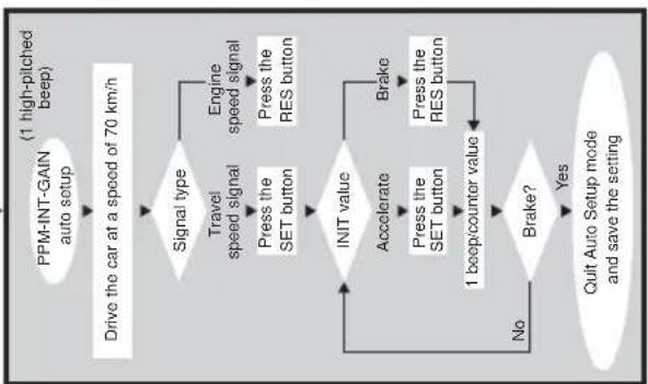
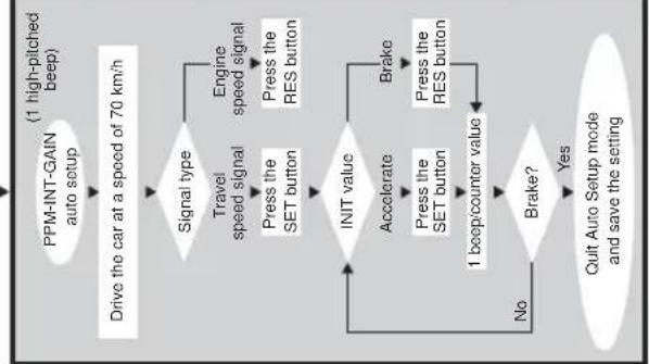
2. Automatic mode
In automatic mode, all three parameters (PPM, GAI and INIT) are synchronized automatically to your vehicle. Following automatic mode, you are still able to adjust all three parameters.
Togo into automatic mode, after performing the steps specified under point 1, depress the brake and press the RES button with brake activated. You will hear a low acoustic signal as confirmation. Release the brake. You will hear a high acoustic signal as confirmation. Repeat the process if you hear more than one acoustic signal.
Drive your vehicle at a speed of 70km / h
Press the SET button for the blue wire as signal input or press the RES button for the yellow wire as a signal input.
Adjustment/training mode
Cruise control switches itself on immediately after pressing the SET- or RESbutton and enters INIT mode. It is possible to optimize the response behaviour in this mode and thus adjust the neutral gear of the throttle lever of the actuator. If cruise control has taken over the speed too slowly, press the SET button to increase the value.
If cruise control has taken over the speed too jerkily, causing oversteer, then the RES button must be pressed. You obtain an acoustic signal as confirmation for each keystroke on the SET or RES button.
Depress the brake to save the adjusted values (PPM, INIT and GAIN).
Now you can call up the program once again by pressing the RES button while the brake is activated. You will hear a low acoustic signal as confirmation. Release the brake. You will hear a low acoustic signal as confirmation after releasing the brake. Restart the program from the beginning by pressing the SET or RES button depending on the signal source. Stop your vehicle to leave the SETUP program and press the SET button 4 times while the brake is activated.
Normally, cruise control should be adjusted optimally for your vehicle.
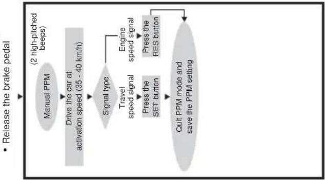
3. PPM adjustment
If you are not satisfied with the range of control of the cruise control, then you can adjust the PPM setting manually.
First start the SETUP-program to reach PPM setting mode.
Now press the RES button twice while the brake is activated. You will hear a low acoustic signal as a confirmation of each keystroke. Release the brake. You will hear two high acoustic signals as a confirmation after releasing the brake. If you do not hear two high acoustic signals, the above-mentioned steps must be performed again.
Drive the vehicle at a speed of 35 - 40km / h to adjust the PPM value. Now press the SET button for the blue cable as the signal input, or the RES button for the yellow cable as the signal input. Cruise control switches itself on immediately after you press the SET or RES button and it switches to normal mode. Depress the brake to save the adjusted values (PPM).
Adjustment/training mode
Stop your vehicle to leave the SETUP program and press the SET button 4 times while the brake is activated.
After each modification of the PPM setting, all previous INIT settings are overwritten with the factory default settings; however, the GAIN setting remains unmodified.
If cruise control now takes over the speed too slowly or too jerkily, the INIT setting must be performed. If cruise control works too slowly or jerkily in normal operation, the GAIN setting must be performed manually.
If cruise control works too slowly or too jerkily in normal operation, the GAIN setting must be performed manually.
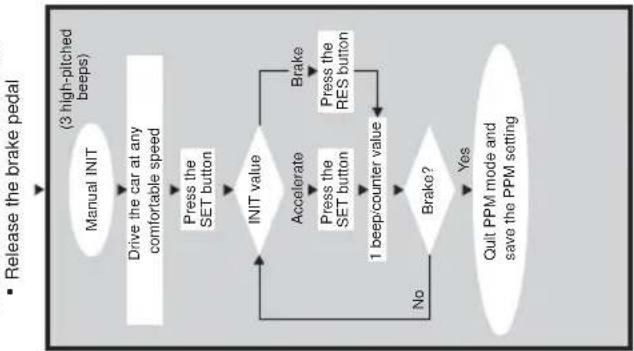
4. INIT mode
You can adjust the sensitivity of the speed takeover inINIT mode.
If cruise control takes over the speed too slowly, the
INIT value must be increased. If the speed is taken over too jerkily, the INIT value must be decreased.
First start the SETUP-program to reach the INIT setting mode.
Now press the RES button three times while the brake is activated. You will hear a low acoustic signal as a confirmation of each keystroke. Release the brake. You will hear three high acoustic signals as a confirmation after releasing the brake. If you do not hear three high acoustic signals, the above-mentioned steps must be performed again.
Drive cruise control at any speed you like above the minimum speed (40 km/h). Now press the SET button until you notice cruise control taking over the speed at which you are driving. Switch off cruise control by activating the brake. Press the SET button again; cruise control should now take over the speed gently. If this is not the case, you can increase the INIT value using the SET button and decrease the value using the RES button. You will hear an acoustic signal for each keystroke.
Adjustment/training mode

Attention! The normal UP and DOWN functions of the SET button and RES button are locked in this mode of operation so that these buttons can be used to input the settings.
Depress the brake to save the adjusted values (PPM, INIT and GAIN). If the INIT value is modified, then cruise control calculates the best possible GAIN value and clears the previous value in the control unit.
Normally, no further setting must be performed in the control unit. Therefore, it is recommended that you leave SETUP mode and test out cruise control in normal operation. Stop your vehicle to leave the SETUP program and press the SET button 4 times while the brake is activated.
If the cruise control reacts too slowly or too sensitively during normal operation, the GAIN value must be modified. Repeat step 1 and 5 again to start GAIN mode.
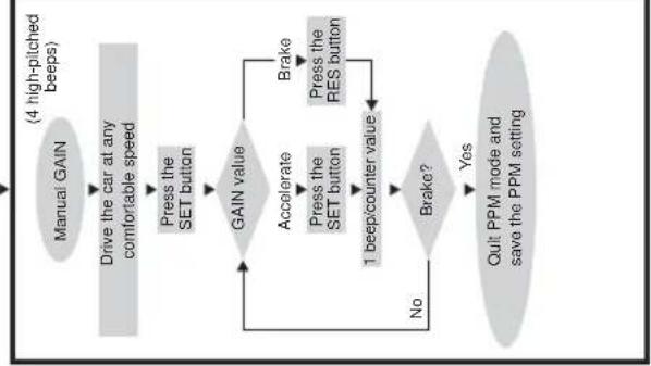
5. GAIN mode
The GAIN value must be increased if the vehicle decelerates or reacts too slowly with the operation of cruise control, e.g. excessive speed loss going up hills or excessive speed increase going down hills.
The GAIN value must be decreased if the vehicle accelerates with the operation of cruise control or if it moves too jerkily. For example: You set a speed of 70km/h and the vehicle speed changes between 65 and 75km/h during normal operation. Normally, the GAIN value, which is calculated after effected INIT setting has been done, ensures the constant normal operation of cruise control. If a modification is necessary, the following procedure should be followed:
First start the SETUP-program to reach GAIN setting mode.
Now press the RES button four times while the brake is activated. You will hear a low acoustic
signal as a confirmation of each keystroke. Release the brake. You will hear four high acoustic signals as a confirmation after releasing the brake. If you do not hear four high acoustic signals, the above-mentioned steps must be performed again.
Adjustment/training mode
Drive the vehicle at a moderate speed to adjust the GAIN value. Press the SET button to activate cruise control. Press the SET button again to increase the GAIN value or press the RES button to decrease the GAIN value. You will hear an acoustic signal as a confirmation of each keystroke.
Below you will find a practical procedure for adjusting the GAIN value optimally after you have set cruise control into the setting mode (see above).
When driving your vehicle at a moderate speed, press the SET button to activate cruise control. Switch off normal operation by activating the brake. Let the vehicle's speed decrease by approx. 25 - 30km / h . Press the RES key to recall the last saved speed. Now look at the vehicle's speedometer. If the speed increases beyond the last saved speed, then the GAIN value must be decreased by pressing the SET button again. If the cruise control has taken up the speed too slowly, press the SET button to increase the GAIN value.
Depress the brake to save the adjusted value. Press the RES button to check the setting. If the setting is not satisfactory, you can modify the GAIN value as described above.
Depress the brake after successful setting to save the value. Point 6 must be observed when leaving SETUP mode.
6. Leaving the SETUP mode
Stop your vehicle to leave the SETUP program and press the RES button 4 times while the brake is activated.
You will hear a long, high acoustic signal as a confirmation that the SETUP program is finished.
Operation of cruise control
ON/OFF-button
Cruise control is switched on by pressing the ON/OFF button once. The LED lights up as confirmation.
If cruise control is switched on, it is switched off by pressing the ON/OFF switch once.
The LED goes out as confirmation.
SET button
- Setting of the currently driven speed if the SET button is pressed and released again immediately. This desired speed is then maintained until:
a) the brake- or the clutch pedal is depressed
b) the unit is switched off via the ON/OFF button
c) the speed of the vehicle is below the lower switch-on speed
d) the speed decelerates by more than approx. 25% when going down a hill.
- If the "SET" button is pressed and held down, the vehicle will accelerate. When the button is released, cruise control will store the speed that has been attained and will maintain that speed.
RES button
If the "RES" button is pressed and immediately released, the last speed that was stored is re-entered, provided that:
a) the unit is switched on via the ON/OFF button;
b) the speed of your vehicle is not below the minimum speed;
c) the brake or clutch pedal is not depressed;
d) the ignition has not been switched off in the meantime;
e) the current speed is not less than 50% of the stored value.
Accelerating and decelerating
When cruise control is activated, you can also make fine adjustments. If you press the "SET" button once, the speed increases by approx. 1.5km / h . If you press the "RES" button once, the speed decreases by approx. 1.5km / h . This function allows you to adjust the speed of your vehicle to the traffic flow or to a speed limit. The cruise control has a memory to store the number of times the buttons have been pressed. For example: If you press the "SET" button three times or the "RES" button five times, the cruise control will accelerate or brake the vehicle by approx. 4.5km / h or 7.5km / h respectively.

Note: If you want to reduce the speed of your vehicle considerably, do not use the "RES" button. Use the "OFF" switch, the brake or the clutch instead, and then set the new speed using the SET button.
Operational test
Start your vehicle and switch on the cruise control by activating the ON/OFF button at the operating element.
While driving at a speed of 40 - 50km / h , press the SET button to activate cruise control. Cruise control should now take over the speed gently and maintain the driven speed constantly. The lowest speed at which cruise control operates is approx. 40km / h .
Adjusting the sensitivity
If cruise control does not switch on gently or the vehicle accelerates or decelerates during normal operation, then appropriate calibrations can be performed to the cruise control sensitivity settings. If cruise control takes over the driven speed to fast or jerkily, the INIT value must be decreased. If cruise control operates too jerkily in normal operation, the GAIN value must be decreased. If the cruise control works too sluggishly and slowly in normal operation, the GAIN value must be increased. All sensitivity settings can be adjusted in the setting mode; see the flowchart on page 67.
Troubleshooting
This section contains a list of possible problems, as well as a list of recommended tests to solve these problems.
The LED of the electronic module does not light up if the buttons of the operating element are pressed.
Check the 8-pin compact connector which branches off from the electronics module and ensure that it is connected properly to the operating element. Check the colour coding on the connection plug of the operating element and ensure that the terminals are inserted properly into the operating element. If they are inserted properly, check the current supply and the earthconnection of the electronics module. The orange cable should have a battery voltage of +12V when the ignition is switched on, and the green cable should have a good earthing connection.
The LED of the electronics module does not light up if the brake is activated.
Ensure that the LED of the electronics module lights up when the buttons of the operating elements are pressed. If it does not light up, the current supply and the earthing connection of the electronics module must be checked. The orange cable should have a battery voltage of +12V when the ignition is switched on, and the green cable should have a good earthing connection.
Check the connection to the brake light switch using a voltmeter. The brown-white cable from the electronics module should be connected to a brake light switch cable which is either fed constantly or via the ignition. The brown cable should be connected to the brake light switch cable, which connects the brake light bulb to the brake light switch. You therefore receive an earth signal from the feed cable to the brake light bulb, if the brake pedal is not activated and a plus signal (+ 12 V) if the brake pedal is activated. The brown-white and the brown cable are interchangeable. Some brake light circuits have a feedcable via ignition, therefore check the cable with the ignition switched on. For safety reasons, cruise control does not operate if there are problems in the original brake light circuit of the vehicle. Therefore, check the brake lights to make sure they are working correctly.
Troubleshooting
The LED does not flash with input of a TACH signal (speedometer signal via the yellow wire).
Wrong TACH signal (speedometer signal). Check the signal with a voltmeter or oscilloscope. Ensure that the signal is between 6 V and 250 V and the frequency range is between 5 Hz and 488 Hz. After checking that the yellow wire is correctly connected, test the signal in the cruise control electronics module once again. Connect the red wire of the voltmeter or oscilloscope to the yellow wire in the connection plug of the electronics module. Install the second cable of the voltmeter or the oscilloscope against the earth. Ensure that the same signal is adjacent to the electronics module as is adjacent to the pickup of the vehicle signal. If this is not the case, recheck the pickup and check the yellow wire fordamage.
Wrong PPM setting. If the identification of the cruise signal is selected via the blue wire, then cruise control does not work via the TACH signal (yellow wire). Change the PPM setting to the input signal via the yellow wire.
The LED does not flash with input of a cruise signal (speed signal via the blue wire)
Wrong cruise signal. Check the signal with a voltmeter or oscilloscope. Ensure that the signal is between 1.5 V and 24 V and the frequency range is between 5 Hz and 8.5 Hz.
After checking that the blue wire is connected correctly, test the signal at the cruise control electronics module once again. Connect the red wire of the voltmeter or oscilloscope to the blue wire in the connection plug of the electronics module. Install the second cable of the voltmeter or the oscilloscope against the earth. Ensure that the same signal is adjacent to the electronics module as is adjacent to the pickup of the vehicle signal. If this is not the case, recheck the pickup and check the blue wire fordamage.
Wrong PPM setting. If the identification of the cruise signal is selected via the yellow wire, then cruise control does not work via the TACH signal (blue wire). Change the PPM setting to the input signal via the blue wire.
Troubleshooting
The engine speed cannot be modified in the diagnostic mode B.
Perform all other tests in the diagnostic mode again to ensure
that the problem does not arise from the electrical connections of the control unit of the cruise control. Switch off the ignition and leave the diagnostic mode. Leave the ignition switched off for a few seconds, then press the SET button and restart the vehicle with the SET button pressed to reach the diagnostic mode.
Repeat test B again. Check the plug connection to the actuator, making sure that the cables are correctly seated and the colour coding of the plug is correct.
Press the SET or RES button in the diagnostic mode B. You should be able to hear the electric motor working in the servo unit after pressing the SET or RES button.
If cruise control reacts too erratically in normal operation and the driving speed changes during normal operation, the GAIN value must be decreased. If cruise control operates too slowly in normal operation, the GAIN value must be increased.
Accessories
Magnet sensor kit AS71430
The magnet sensor kit is used to generate a cruise signal. There are numerous assembly possibilities available. The magnets are attached with double-sided adhesive tape to the cardan shaft or drive shaft. Use the supplied cable clips for the final fastening of the magnets.
Accessories
Vehicles equipped with front wheel drive (see 念 11)
Prevent the rear wheel from moving away, apply the hand brake and move the gearshift to neutral. Lift the front of the vehicle high enough that there is sufficient working space available. Support the front of the vehicle using support brackets. Never work under a vehicle that is not adequately secured. Fasten the sensor to the mounting and determine the installation position. This position should be as close as possible to the gear. The suitable assembly location for the magnets is the inner joint of the drive shaft. Fix 2 magnets to the joint with double-sided adhesive tape and secure the fixed magnets with the cable clips after distributing these uniformly on the joint.
Position the sensor so that there is a distance of approx. 3-5 mm arises between the magnets and the cruise sensor. Ensure that the distance between sensor and the magnets does not decrease or become larger than 5 mm as a result of the vertical movement of the drive shaft.
Vehicles with rear-wheel drive (see 12)
Prevent the front wheels from moving away and move the gearshift to neutral. Lift the rear of the vehicle high enough that there is sufficient workingspace available. Support the front of the vehicle using support brackets. Never work under a vehicle that is not adequately secured. Fasten the sensor to the mounting and determine the installation position. This position should be as close as possible to the gear. The suitable assembly location for the magnets is directly in the gearbox. Fix 1 or 2 magnets on the cardan shaft with double-sided adhesive tape and fasten the fixed magnets with the cable clips after you have distributed these evenly on the joint. Position the sensor sothat there is a distance of approx. 3 - 5mm between the magnets and the cruise sensor. Ensure that the distance between sensor and magnets does not decrease or becomes larger than 5mm as a result of the vertical movement of the drive shaft.
Speedometer shaft generator MS-AA-144 (see I 3)
The speedometer shaft generator is used to generate a cruise signal in vehicles with a screwed speedometer shaft. When using the speedometer shaft generator in vehicles with manual transmission, it is absolutely imperative to install engine overspeed protection.
STANDARD MODE
- Start the engine.
ss the ON/OFF button on the control module.
Press and hold down the brake pedal. Press the SET button for times
Adjustment Mode
- Press and hold down the brake pedal
- Press the RES button four times
- Release the brake pedal
- Press and hold down the brake pedal
- Press the RES button once
- Release the brake pedal
Quitting setup mode: Press the brake pedal and hold it down; press the SET button four times (you will hear a long, high-pitched beep)
Disposal instruction
Please note, that electrical units contain a great number of recyclable materials as well as environmentally hazardous components. Please ensure, in your own interests and in the interest of the environment, that these components are disposed off only in the intended and appropriate manner.
Technical data
Operating voltage: 12 volts
Current consumption: max 10.5 A
Operating temperature: -40° to +85° C
ABE No. 90669
Subject to technical changes!
I also quadrilvocuou la tccua C2
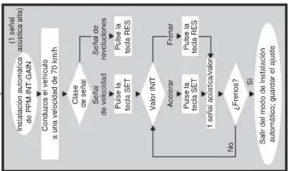
Modo de ajuste
m = 311
M
icu
(3)
fas
set
eña
lse
a S
mac
ai
m
icu
(3)
fas
se
eña
Ta S
Lal
1
一
Magnetsensorsett AS71430
Roman Hill Business Park
UK-Broadmayne
Fon: +44 1305 854000
Fax: +44 1305 854288
E-Mail: sales@waeco.co.uk
Overseas + Middle East

WAECO Pacific Pty. Ltd.
1 John Duncan Court
Varsity Lakes QLD 4227
Fon: +61 7 55076000
Fax:+61755076001
E-Mail: sales@waeco.com.au

WAECO Impex Ltd.
Suites 3210-12·32/F·Tower 2
The Gateway 25 Canton Road
Tsim Sha Tsui Kowloon
Hong Kong
Fon: +852 24632750
Fax: +852 2463
E-Mail: info@waeco.com.hk

WAECO Impex Ltd.
Taipei Office
2 FL-3 · No. 56 Tunhua South Rd, Sec 2
Taipei 106, Taiwan
Fon: +886 2 27014090
Fax: +886 2 27060119
E-Mail: marketing@waeco.com.tw

WAECOMiddle East FZCO
R/A 8, SD 6
Jebel Ali, Dubai
Fon: +971 4 8833858
Fax:+97148833868
E-Mail: waeco@emirates.net.ae

WAECO USA, Inc.
8 Heritage Park Road
Clinton, CT 06413
Fon: +1 860 6644911
Fax: +1 860 6644912
E-Mail: customercare@waecousa.com

- List of contents
- Information for using the installation instructions
- Warning! Safety instruction:
- Caution! Safety precaution:
- Safety and installation instructions
- Always ensure that the connection is properly earthed!
- Scope of delivery
- Article Parts No.
- Piece Description
- Required tools
- Command module
- Variable throttle lever - stroke
- Cable - changing stroke
- Fitting the throttle lever
- Possibility 1
- Possibility 2
- Possibility 3
- Electronics module
- Cable harness
- Green/red, black, pink/red and blue/red
- Orange cable
- Green cable
- Brown and brown-white cable
- Yellow and blue signal cable
- Speed signal
- Engine speed (RPM)
- Blue cable
- Yellow cable
- Engine overspeed protection
- Vehicles with automatic transmission
- Vehicles with manual transmission
- Pick-up of the cruise or speed signal
- Cruise signals
- Engine speed signals
- Diagnostic mode
- Diagnostic mode A
- Diagnostic mode B
- Diagnostic mode C
- Safety devices
- Adjustment/training mode
- Starting SETUP mode
- Automatic mode
- PPM adjustment
- INIT mode
- GAIN mode
- Leaving the SETUP mode
- Operation of cruise control
- ON/OFF-button
- SET button
- RES button
- Accelerating and decelerating
- Operational test
- Adjusting the sensitivity
- Troubleshooting
- The LED of the electronic module does not light up if the buttons of the operating element are pressed.
- The LED of the electronics module does not light up if the brake is activated.
- The LED does not flash with input of a TACH signal (speedometer signal via the yellow wire).
- Accessories
- Magnet sensor kit AS71430
- Vehicles equipped with front wheel drive (see 念 11)
- Vehicles with rear-wheel drive (see 12)
- Speedometer shaft generator MS-AA-144 (see I 3)
- STANDARD MODE
- Adjustment Mode
- Disposal instruction
- Technical data
- Modo de ajuste
- Overseas + Middle East
Brand : WAECO
Model : MagicSpeed MS700
Category : Cruise control