
GW90836A - Switch Gewiss - Free user manual and instructions
Find the device manual for free GW90836A Gewiss in PDF.

| Product type | 4-channel actuator for KNX system |
| Brand | Gewiss |
| Model | GW90836A |
| Category | Switch / Actuator |
| Use | Indoor, dry rooms |
| Power supply | KNX bus (29 V DC typ., max consumption 10 mA) |
| Control elements | 1 programming button, 4 local control push buttons |
| Display | 1 red LED (programming), 4 green LEDs (output status) |
| Number of channels | 4 |
| Contact type | 4 relays 16 AX with voltage-free NO contact |
| Max switching current | 16 A (AC1), 16AX (140 µF, EN 60669-1) |
| Max power per load type | Incandescent/halogen lamps 230V: 3000W; toroidal transformers: 3000W; electronic transformers: 2000W; compact fluorescent lamps: 80×23W |
| Max heat dissipation | 4 W |
| Operating temperature | -5 to +45 °C |
| Storage temperature | -25 to +70 °C |
| Max relative humidity | 93 % (non-condensing) |
| Bus connection | 2-pole plug terminal, ∅ 1 mm |
| Electrical connections | Removable screw terminals, max cross-section 4 mm² |
| Protection degree | IP20 |
| Dimensions | 4 DIN modules (approx. 72 mm width) |
| Reference standards | Low Voltage Directive 2006/95/EC, Electromagnetic Compatibility Directive |
| Main functions | ON/OFF switching, adjustable delay, priority commands, scene management (up to 8 per channel) |
| Installation | On DIN 35 mm rail, by qualified personnel, disconnect power before connection |
| Maintenance | No maintenance required; clean with dry cloth |
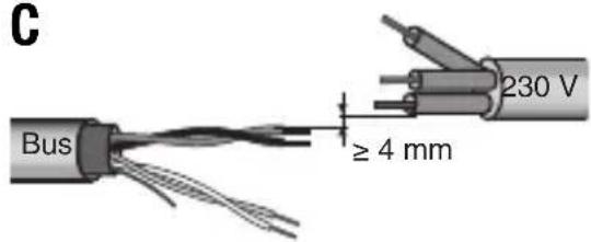
| Safety | Comply with national standards and IEC 60364/HD 60364; maintain 4 mm distance between bus and power cables |
Frequently Asked Questions - GW90836A Gewiss
User questions about GW90836A Gewiss
0 question about this device. Answer the ones you know or ask your own.
Ask a new question about this device
Download the instructions for your Switch in PDF format for free! Find your manual GW90836A - Gewiss and take your electronic device back in hand. On this page are published all the documents necessary for the use of your device. GW90836A by Gewiss.
USER MANUAL GW90836A Gewiss
C
① Uscita relè 1 - Output relay 1 - Sortie relais 1 - Salida relé 1 - Relaisausgang 1
② Uscita relè 2 - Output relay 2 - Sortie relais 2 - Salida relé 2 - Relaisausgang 2
③ Pulsante comando locale relè 1
Relay 1 local command button - Bouton-poussoir de commande locale du relais 1 - Pulsador mando local de relé 1 - Lokaler Relaissteuertaster 1
④ LED stato relè 1
Relay 1 status LED - LED état du relais 1 - LED de estado de relé 1 - LED Relaisstatus 1
⑤ Pulsante comando locale relè 2
Relay 2 local command button - Bouton-poussoir de commande locale du relais 2 - Pulsador mando local de relé 2 - Lokaler Relaissteuertaster 2
⑥ LED stato relè 2
Relay 2 status LED - LED état du relais 2 - LED de estado de relé 2 - LED Relaisstatus 2
⑦ LED stato relè 3
Relay 3 status LED - LED état du relais 3 - LED de estado de relé 3 - LED Relaisstatus 3
⑧ Pulsante comando locale relè 3
Relay 3 local command button - Bouton-poussoir de commande locale du relais 3 - Pulsador mando local de relé 3 - Lokaler Relaissteuertaster 3
⑨ LED di programmazione
Programming LED - LED de programmation - LED de programación - Programmierled
⑩ Tasto di programmazione
Button key for programming - Touche de programmation - Tecla de programación - Programmiertaste
⑪ LED stato relè 4
Relay 4 status LED - LED état du relais 4 - LED de estado de relé 4 - LED Relaisstatus 4
⑫ Pulsante comando locale relè 4
Relay 4 local command button - Bouton-poussoir de commande locale du relais 4 - Pulsador mando local de relé 4 - Lokaler Relaissteuertaster 4
⑬ Uscita relè 3 - Output relay 3 - Sortie relais 3 - Salida de relé 3 - Relaisausgang 3
⑭ Uscita relè 4 - Output relay 4 - Sortie relais 4 - Salida de relé 4 - Relaisausgang 4
⑮ Terminali bus - Bus terminals - Bornes du bus - Conectores bus - Busanschlüsse
INDICE
AVVERTENZE GENERALI
PROGRAMMING WITH THE EASY CONFIGURATOR.... 22
IN SERVICE 25
TECHNICAL DATA 27
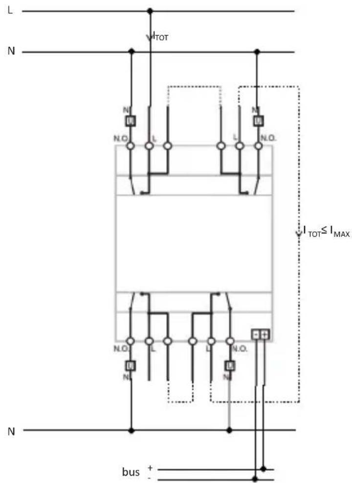
If the dual terminals are used for phase (L) entry and exit, check that the total circulating current ( I_TOT ) does not exceed the max current ( I_MAX ) indicated in the "Technical data" section of the instruction sheet.
GENERAL RECOMMENDATIONS
Warning! The safety of this appliance is only guaranteed if all the instructions given here are followed scrupulously.
These should be read thoroughly and kept in a safe place.
Chorus products can be installed in environments which are dust-free and where no special protection against the penetration of water is required.
They shall be installed in compliance with the requirements for household devices set out by the national standards and rules applicable to low-voltage electrical installations which are in force in the country where the products are installed, or, when there are none, following the international standard for low-voltage electrical installations IEC 60364, or the European harmonization document HD 60364.
Gewiss sales organization is ready to provide full explanations and technical data on request.
Pack Contents
n. 1 Easy 4-channel 16 AX actuator - DIN rail mounting
n. 1 Bus terminal
n. 4 Screw terminals
n. 1 Cover with screw
n. 1 Installation and user manual
Briefly
The Easy 4-channel 16 AX actuator – DIN rail mounting allows up to 4 different electrical loads to be activated/deactivated separately by means of 4 x 16 AX relays, each one fitted with 1 NO output contact. The switchover command of the relay can arrive from command devices or sensors of the Home Automation system, via the KNX BUS, or be locally generated by the front push-buttons.
The actuator is powered from the BUS line and has 4 front green LEDs for signalling the output status. The device sends information to the bus about the relay status (ON = contact closed, OFF = contact open) when switching on, receiving a command and in the case of a command from a local push-button.
Each output channel of the actuator can be configured separately and allows the ON/OFF command of the controlled loads, execution of timed commands, scene management and execution of priority commands to force the output status. The operating modes can be used simultaneously.
This means, for instance, that the device can switch a light on and off, or automatically switch it on and off after a certain pre-established time, simply on the basis of the command received.
The module is assembled on the DIN rail, inside the electric boards or junction boxes.
Functions
Each channel of the actuator can be configured with the Easy controller to carry out the following functions:
LOAD ACTIVATION AND DEACTIVATION
The actuator channel activates or deactivates the electrical load when it receives the ON/OFF commands sent, for example, from a contact interface or from a push-button panel configured as Cyclic ON/OFF switchover or Fronts management.
The green LED turns on when the relay contact is closed.
EXECUTION OF TIMED COMMANDS
The actuator activates the electrical load connected for a time set with the Switch-on time parameter, deactivating it when this time is up. This is the setting, for instance, for the stairs light. If, during the activation period, the actuator receives a new ON command with timer, time starts again from the beginning.
GENERAL DESCRIPTION
When an OFF command is received or when a scene is activates that includes the actuator OFF command, the relay is deactivated and the countdown cancelled.
The switch-off warning can be enabled with the Prewarning time parameter: in this case the relay opens briefly (the light turns off momentarily) when, at the end of the time set, there is the time left set by the parameter. It will thus be possible - if necessary - to send a new ON command with timer before the light turns off. The green LED turns on when the relay contact is closed.
EXECUTION OF PRIORITY COMMANDS
The actuator switches the relay to the (ON or OFF) state transmitted by the device (contact interface) that sends the priority command.
Until it receives a command to stop forcing, the actuator ignores all the other commands received including those from the front push-buttons.
If no other commands are received, when forcing is finished the actuator returns to the state before forcing was activated. Otherwise, it will return to the state corresponding to the last command received.
The green LED turns on when the relay contact is closed.
SCENE MANAGEMENT
Each actuator channel can store and execute up to 8 scenes, each scene associated with the ON or OFF status of the relay. It is not possible to associate a scene with a timed activation.
To associate an actuator status with a scene it is necessary to control the output of the status required (ON/OFF) prior to storing.
The green LED turns on when the relay contact is closed.
INSTALLATION

ATTENTION: the device must only be installed by qualified personnel, observing current regulations and the guidelines for KNX installations.
Recommendations for installing the KNX
- The length of the bus line between the actuator and the power supply must not exceed 350 metres.
- The length of the bus line between the actuator and the furthest away KNX device must not exceed 700 metres.
- To avoid unwanted signals and overvoltages do not use ring circuits.
- Keep a distance of at least 4 mm between the individually insulated cables of the bus line and those of the electricity line (figure C).
- Do not damage the electrical continuity conductor of the shielding (figure D).
ATTENTION: The bus signal cables that are not used and the electrical continuity conductor must never touch any live elements or the earthing conductor!
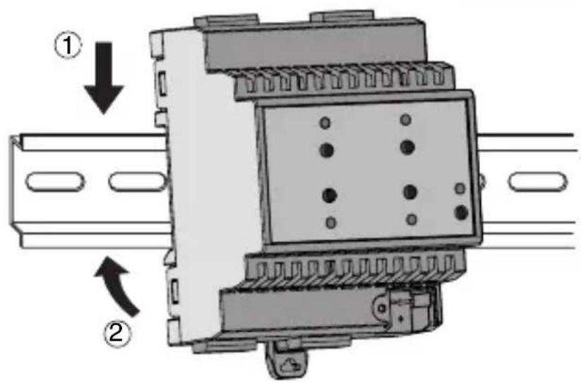
Assembly on the DIN rail
Mount the 4-channel actuator on a 35 mm DIN rail in the following way (figure E):
- Insert the upper device coupling in the DIN rail.
- Turn the device and lock it on the DIN rail, using the fixing tab.
Electric connections
ATTENTION: disconnect mains voltage before connecting the device to the mains!
Figure B shows a diagram of the electrical connections.
- Connect the red wire of the bus cable to the red terminal (+) of the terminal and the black wire to the black terminal (-). Up to 4 bus lines can be connected to the bus terminal (same coloured wires on the same terminal) (figure F).
- Insulate the shield, the electrical continuity conductor and the other white and yellow wires of the bus cable (if a 4-conductor bus cable is being used), that are not necessary (figure D).
- Insert the bus terminal in the device's pins. The correct insertion direction is determined by the fixing guides. Insulate the bus terminal with the cover to be screwed onto the device.
The cover guarantees the minimum separation distance of 4 mm between the power cables and the bus cables (figure G). - Connect the loads to the relevant supplied screw terminals, making sure the current limits specified in the Technical Data are not exceeded. Insert the terminals in the actuator output connectors, and check they are correctly inserted (figure H).
Initialisation with Easy Controller
- Power the device via the bus.
- Follow one of these procedures for the system to acquire the device:
• Automatic acquisition:
- select the "Find/Configure" or "Scan" command on the "System" menu
- Manual acquisition:
- select the "Add device" menu from the "System" menu;
- press the programming key briefly (< 2 seconds). The programming LED turns on during the acquisition process (figure A).
The device acquired is listed with a number assigned to it, a product code and a list of the channels in the "Devices" view.
Initialisation with the Easy base unit (GW 90 831)
- Power the device via the bus.
- Follow one of these procedures for the system to acquire the device:
- Automatic acquisition (the device still has the factory default settings):
- choose the "New Function Application" → or the "Edit Function → Application" menu from the Easy base unit: the device is recognised automatically.
- Manual acquisition (factory default settings have been changed):
- choose the "Find Device Application" → from the Easy Base unit;
- press the programming key briefly (< 2 seconds). The programming LED turns on during the acquisition process (figure A).
The device acquired by the Easy base unit is listed, with the number assigned to it, in the channels of the "New Function → Application" or "Edit Function → Application" menu.
Programme the actuator with the Easy controller (GW 90 837 / GW 90 838 / GW 90 840) or with the Easy base unit (GW 90 831).
Each output to programme can be selected as wanted:
- pressing the local command push-button: this channel will then be highlighted on the list of channels;
- directly from the list of channels.
The functions can be created once the devices have been selected.
| Name of the functions | |
| toggle load activation or deactivation | |
| edges load activation or deactivation | |
| timer mode load activation with timer | |
| priority control actuation of the priority commands | |
| scene actuation of the scenes | |
| switch-on time | |
| prewarning time | |
For more details about the programming procedures please refer to the Easy base unit or Easy Controller documentation.
Configuration parameters (Easy)
Once the function wanted has been created, the actuator's functioning parameters can now be set.
The available parameters, in relation to the function created, are listed in the tables given below.
The value underlined is the default value.
| Function: timer mode | |
| Parameter: switch-on time | |
| not active no timing | |
| 1 second relay activated for 1 second | |
| 2 seconds relay activated for 2 seconds | |
| 3 seconds relay activated for 3 seconds | |
| 5 seconds relay activated for 5 seconds | |
| 10 seconds relay activated for 10 seconds | |
| 15 seconds relay activated for 15 seconds | |
| 20 seconds relay activated for 20 seconds | |
| 30 seconds relay activated for 30 seconds | |
| 45 seconds relay activated for 45 seconds | |
| 1 minute relay activated for 1 minute | |
| 1 minutes 15 sec. relay activated for 1 minute and 15 seconds | |
| 1 minutes 30 sec. relay activated for 1 minute and 30 seconds | |
| 2 minutes relay activated for 2 minutes | |
| 2 minutes 30 sec. relay activated for 2 minute and 30 seconds | |
| 3 minutes relay activated for 3 minutes | |
| 5 minutes relay activated for 5 minutes | |
| 15 minutes relay activated for 15 minutes | |
| 20 minutes relay activated for 20 minutes | |
| 30 minutes relay activated for 30 minutes | |
| 1 hour relay activated for 1 hour | |
| 2 hours relay activated for 2 hours | |
| 3 hours relay activated for 3 hours | |
| 5 hours relay activated for 5 hours | |
| 12 hours relay activated for 12 hours | |
| 24 hours relay activated for 24 hours | |
PROGRAMMING WITH THE EASY CONFIGURATOR
| Function: timer mode | |
| Parameter: prewarning time | |
| no warning no warning15 seconds warning 15 seconds before deactivation of the relay30 seconds warning 30 seconds before deactivation of the relay1 minute warning 1 minute before deactivation of the relay | |
Using the local command push-button
With the local command push-buttons (figure A) you can control cyclic ON/OFF switching over, reversing the status of the relay each time it is pressed. If a priority command is active, the local commands will not be executed.

ATTENTION: the local command push-buttons will only work if BUS voltage is present.
Behaviour of supply fall/reset on the bus
If BUS voltage drops below 18 V dc for more than 1,5 ms the actuator, with the factory default settings, will not carry out any changes to the status of the output contacts. The behaviour of the outputs when BUS voltage drops can be configured in the following way.
Configuration mode input:
- press the programming key: the red programming LED turns on
- press the local command push-buttons 1 and 4 simultaneously for at least 3 seconds
- wait until the 4 LEDs blink once
When you are in the configuration mode, the contacts of all the channels are opened and the LEDs show the current configuration status of each single channel, as per the table.
| CHANNELS 1..4 LED4 CHANNEL STATUS WHEN VOLTAGE DROPS | |
| Off Open | |
| On Closed | |
| Blinking No change | |
The setting of each single channel can be changed with its relative key, so as to scroll all the configurations available in sequence.
IN SERVICE
Configuration mode output:
- to save the new settings: press the programming push-button. The programming LED turns off;
- to exit without saving the settings: wait 10 seconds (from when you last pressed a button). The end of the configuration mode is signalled when the programming LED turns off.
When you exit the configuration mode the status of the channels before accessing the procedure is restored.
In this configuration phase, the messages from the bus are ignored (they are managed when configuration is exited).
When bus voltage is restored the contacts stay in the state they were in when voltage dropped.
Maintenance
The device does not require any maintenance. Use a dry cloth if cleaning is required.
TECHNICAL DATA
Communication KNX Bus
Power supply via the KNX bus, 29 V dc SELV
Bus cable KNX TP1
Bus current consumption 10 mA max
Command elements 1 miniature programming key
4 push-buttons for local relay command
Display elements 1 red programming LED
4 green LEDs for signalling output status
Actuation elements 4 x 16 AX relays with NO potential free contact
Maximum switchover current 16 A (AC1)
16AX (140 μF ref. EN 60669-1) fluorescent loads
with maximum surge current 400A (200 μs)
Maximum power for load type Incandescent lamps (230Vac): 3000W
Halogen lamps (230Vac): 3000W
Loads controlled by toroidal transformers: 3000W
Loads controlled by electronic transformers: 2000W
Low consumption lamps
(compact fluorescent lamps): 80x23W
Maximum dissipated power 4W
Ambit of use Indoors, dry places
Operating temperature -5 to +45 °C
Storage temperature -25 to +70 °C
Relative humidity Max 93% (non condensative)
Bus connection Coupling terminal, 2 pin ∅ 1 mm
Electrical connections Extractable screw terminals
Max. cable section: 4 mm²
Protection ratings IP20
Dimension 4 DIN modules
Reference standard Low voltage directive 2006/95/EC
Electromagnetic Compatibility Directive 2004/108/EC
EN50428, EN50090-2-2
Certifications KNX/EIB
SOMMAIRE
CONSIGNES GÉNÉRALES ...... page 30
DESCRIPTION GENERALE 31
INSTALLATION 33
PROGRAMMATION AVEC EASY CONTROLLER 35
EN SERVICE 38
CONSIGNES GÉNÉRALES
Communication Bus KNX
Alimentation Par bus KNX, 29 V cc SELV
Câble bus KNX TP1
2004/108/CE, EN50428, EN50090-2-2
Certifications KNX/EIB
ÍNDICE
(fluorescentes compactos): 80x23W
2004/108/CE, EN50428, EN50090-2-2
ALLGEMEINE HINWEISE
Halogenlampen (230VAC): 3000W
2004/108/EG, EN50428, EN50090-2-2
① Cavo bus - Bus cable - Câble bus - Cable bus - Buskabel
② Conduttore di continuità elettrica - Electrical continuity conductor - Conducteur de continuité électrique - Conductor de continuidad eléctrica - Beidraht
③ Schermatura - Shielding - Blindage - Apantallamiento - Schirm
E
F
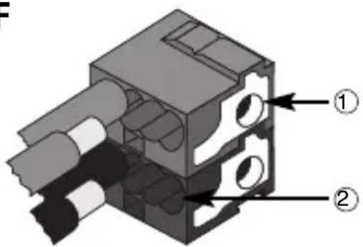
① Connessione dispositivo bus
Bus device connection - Connexion du dispositif bus - Conexión dispositivo bus - Anschluss Busgerät
natural_image
Technical diagram of an electronic device with ports and a mechanical component, no visible text or symbols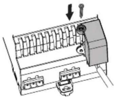
natural_image
Diagram of a mechanical device with internal components and directional arrows indicating movement (no text or symbols)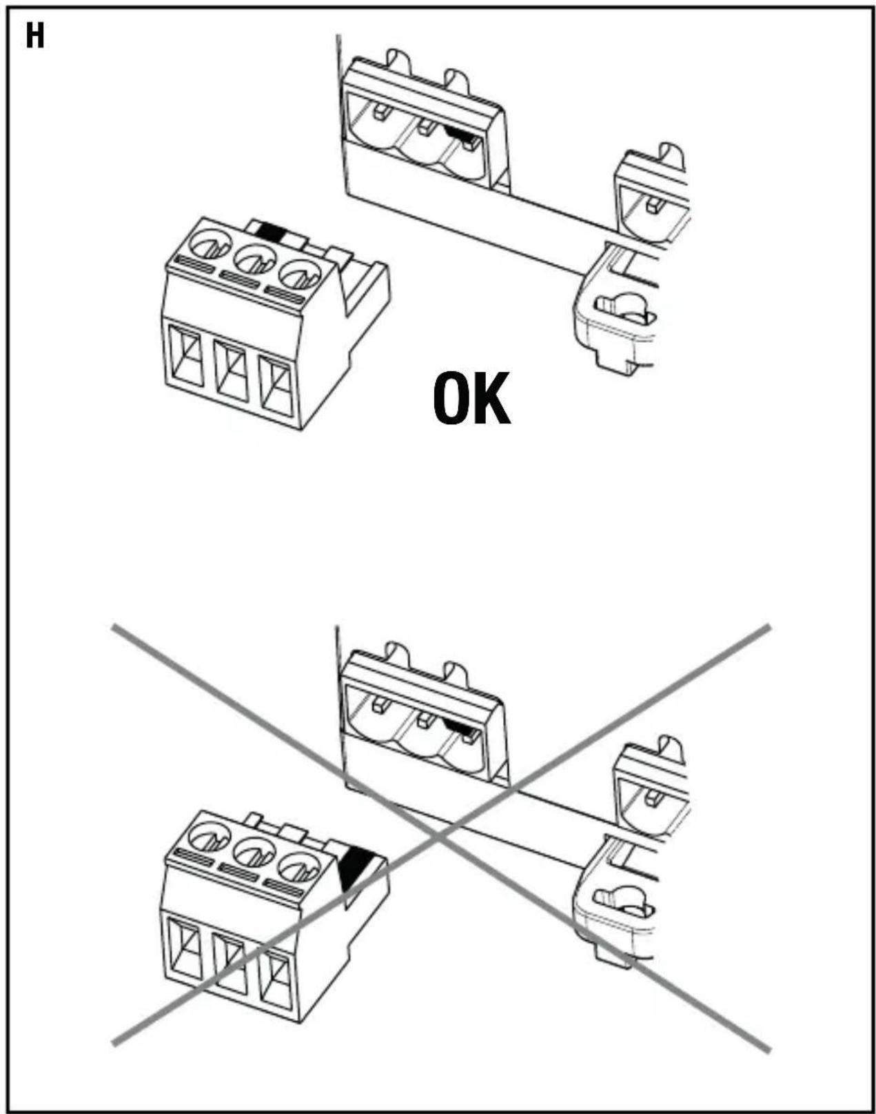

- INDICE
- AVVERTENZE GENERALI
- GENERAL RECOMMENDATIONS
- Pack Contents
- Briefly
- Functions
- LOAD ACTIVATION AND DEACTIVATION
- EXECUTION OF TIMED COMMANDS
- GENERAL DESCRIPTION
- EXECUTION OF PRIORITY COMMANDS
- SCENE MANAGEMENT
- INSTALLATION
- Recommendations for installing the KNX
- Assembly on the DIN rail
- Electric connections
- ATTENTION: disconnect mains voltage before connecting the device to the mains!
- Initialisation with Easy Controller
- Initialisation with the Easy base unit (GW 90 831)
- Configuration parameters (Easy)
- PROGRAMMING WITH THE EASY CONFIGURATOR
- Using the local command push-button
- Behaviour of supply fall/reset on the bus
- Configuration mode input:
- IN SERVICE
- Configuration mode output:
- Maintenance
- TECHNICAL DATA
- SOMMAIRE
- CONSIGNES GÉNÉRALES
- ÍNDICE
- ALLGEMEINE HINWEISE
Brand : Gewiss
Model : GW90836A
Category : Switch