
GW90857 - Switch Gewiss - Free user manual and instructions
Find the device manual for free GW90857 Gewiss in PDF.

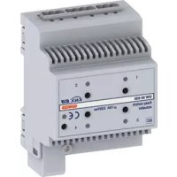
| Product type | 4-channel 6 A KNX motor control actuator for DIN rail |
| Brand | Gewiss |
| Model | GW90857 |
| Dimensions | 4 DIN modules (width 72 mm, depth 64 mm, height 90 mm) |
| Weight | Approximately 200 g |
| Power supply | KNX bus 29 V DC SELV (10 mA max); auxiliary 230 V AC (phase + neutral) for local control without bus |
| Communication | KNX TP1 bus |
| Number of channels | 4 independent channels (up/down) |
| Load type | Motors of blinds, roller shutters, Venetian blinds (6 A max per motor); resistive loads (8 A max) |
| Output contacts | 8 NO contacts (4 channels × 2 relays) – 8 A, 250 V AC (cosφ=1) |
| Main functions | Up/down control, stop, slat adjustment (Venetian blinds), weather alarm management (wind, rain, frost), blocking, forcing, scenes (8), automatic mode, local control via front pushbuttons |
| LED indicators | 1 red programming LED; 8 green LEDs (2 per channel) for output status (up/down) |
| Control elements | 1 miniature programming button; 8 local control buttons (2 per channel) |
| Maintenance and cleaning | No maintenance required. Clean with a dry cloth. |
| Safety | Installation by qualified personnel only, compliant with national standards and KNX directives. Disconnect mains voltage before connection. Maintain a distance of 4 mm between bus cables and mains cables. |
| Spare parts and repairability | Bus terminal, screw terminals (×7), cover with screws. The device is not user-repairable; contact Gewiss after-sales service. |
| General information | KNX certified. Compliant with Low Voltage Directive (2006/95/EC) and Electromagnetic Compatibility (2004/108/EC). Standards EN50428, EN50090-2-2, EN60669-2-1. Operating temperature: -5 to 40 °C. Protection degree: IP20. |
Frequently Asked Questions - GW90857 Gewiss
User questions about GW90857 Gewiss
0 question about this device. Answer the ones you know or ask your own.
Ask a new question about this device
Download the instructions for your Switch in PDF format for free! Find your manual GW90857 - Gewiss and take your electronic device back in hand. On this page are published all the documents necessary for the use of your device. GW90857 by Gewiss.
USER MANUAL GW90857 Gewiss
When making the parallel connection of several motors, always use support or insulation relays.
Warning! The safety of this appliance is only guaranteed if all the instructions given here are followed scrupulously. These should be read thoroughly and kept in a safe place. Chorus products can be installed in environments which are dust-free and where no special protection against the penetration of water is required.
They shall be installed in compliance with the requirements for household devices set out by the national standards and rules applicable to low-voltage electrical installations which are in force in the country where the products are installed, or, when there are none, following the international standard for low-voltage electrical installations IEC 60364, or the European harmonization document HD 60364. Gewiss sales organization is ready to provide full explanations and technical data on request.
Gewiss SpA reserves the right to make changes to the product described in this manual at any time and without giving any notice.
Pack content
n. 1 KNX 4-channel shutter actuator 6 A - DIN rail
n. 1 Bus terminal
n. 7 Screw terminals
n. 1 Cover with screw
n. 1 Installation and user manual
Summary
The KNX 4-channel shutter actuator 6 A - DIN rail controls the movement of 4 independent motors of shutters, curtains and Venetian blinds. The 2 output relays for each channel, one for UP and one for DOWN movements, are interlocked to avoid damage to the connected motor.
The movement commands can be accessed through Building Automation control or sensor devices using the KNX bus, or they can be generated locally using the two front buttons. The loads can be commanded via local command push Buttons, even without a BUS voltage: in this case the device requires the 230V AC auxiliary power supply provided by the special terminals. The actuator is powered by the bus line and it is equipped with 2 green front LEDs for each channel which indicate the shutter movement status (UP/DOWN). The actuator can function in shutter or blind mode, and is capable of handling actuation following priority, scene and alarm commands.
The operating methods can be used simultaneously.
Functions
The engine command actuator is able to simultaneously manage movement, alarm, lock and priority commands. When set on Automatic operation, the device can also carry out autonomous movements to take advantage of sunlight for heating, or to keep the room cool. In the case of several modes activated simultaneously, the actuator will carry out the one with the highest priority. The priority established amongst the various functions (from minimum to maximum) is the following:
- BUS voltage fall status (stop/no action)
- 230V voltage fall status (stop/no action)
- Override status when BUS voltage is reset
- Value of lock object when BUS voltage is reset
- Alarm status when BUS voltage is reset
- Behaviour of actuator when BUS voltage is reset
- Front button keys (test function)
- Override
- Lock
- Weather alarms
Automatic mode
Automatic calibration - Scene/Command position blade/Command position/Stop (blade adjustment)/Movement.
MAX PRIORITY
MIN PRIORITY
GENERAL DESCRIPTION
The two green status indicator LEDs for each channel light up when the contacts with the respective relays are closed (UP/DOWN).
SHUTTER MOVEMENT HANDLING
It raises or lowers the shutters, or stops the movement when it receives the relative command.
If the Stop command is not sent, the motor will only stop at the end of the Movement Time:
The shutters must therefore be fitted with stroke end sensors or an autonomous clutch.
BLIND MOVEMENT HANDLING

WARNING: In order to fully exploit this mode, the blinds must be able to mechanically orientate their laths with short UP/DOWN movements performed by the motor.
The blinds can be raised or lowered, or the movement can be stopped using the relative command. When a blind stops, the actuator receives a short movement command and the laths are rotated.
If the Stop command is not sent, the motor will only stop at the end of the Movement Time: the blinds must therefore be fitted with stroke end sensors or an autonomous clutch.
ALARMS CONTROL
Up to 5 different weather alarms can be managed: 3 wind alarms, a rain alarm and an ice alarm.
If activated, the actuator moves the load (venetian blinds, motorised curtain) when it receives an alarm message from a wind, rain or ice sensor.
It is possible to monitor sensor operation by activating a 'surveillance time' for each alarm, with the sensor itself receiving regular "no alarm" messages; if a message is not received within this set time, the actuator interprets it as a sensor fault and consequently brings the load to the set safety position.
The alarm status continues until the actuator receives a "no alarm" message. It is possible to define the intrinsic priority from amongst the various weather alarms.
GENERAL DESCRIPTION
PERFORMING PRIORITY CONTROLS
When an override activation command is received, the actuator brings the load to the position defined by the priority command (UP or DOWN). The actuator ignores any other commands received (including weather alarm and lock) until the priority command is withdrawn.
The behaviour of the actuator upon withdrawal of the priority command can be defined during the programming phase.
LOCK EXECUTION
It is possible to lock the device-connected load in a specific position (that can be set) when the lock activation command is received; any other command received (apart from the override activation command) will be ignored until this function is deactivated.
SCENE MANAGEMENT
The actuator can manage up to 8 scenes, each of which reproduces a specific position for the connected load.
It is possible to store a particular position by means of the relative scene learning command; the learning function can be enabled/disabled via the KNX command.
AUTOMATIC MODE
The device can carry out autonomous movements to take advantage of sunlight, for instance to warm the room; you can define the position to which the load must move in order either to protect the room against direct sunlight (therefore keeping it cool), or to exploit the sun to warm the room.
Using the automatic mode selection commands, you can activate/deactivate one of the above-mentioned functions.

WARNING: the installation of the device must be exclusively done by qualified personnel, following the regulations in force and the guidelines for KNX installations.
Warnings for KNX installations
- The length of the bus line between the actuator and the power supply unit must not exceed 350 metres.
- The length of the bus line between the actuator and the most distant KNX device to be controlled must not exceed 700 metres.
- Do not create ring circuits so as to prevent undesirable signals and overloads.
- Keep a distance of at least 4mm between the individually insulated cables of the bus line and those of the electric line (figure C).
- Do not damage the electrical continuity conductor of the shielding (figure D).
WARNING: the unused bus signal cables and the electrical continuity conductor must never touch elements under power or the earth conductor!
Assembly on DIN rail
Assemble the 4 channels shutter actuator 6 A on a 35mm DIN rail in the following way (figure G):
- Insert the upper coupling of the device in the DIN rail.
- Turn the device and lock it on the DIN rail, using the fixing tab.
Electrical connections
WARNING: cut off mains power before connecting the device to the electricity mains!
Figure B shows the electrical connections diagram.
- Connect the bus cable's red wire to the terminal's red connector (+) and the black wire to the black connector (-). Up to 4 bus lines (wires of the same colour in the same connector) can be connected to the terminal (figure E).
- Insulate the screen, the electrical continuity conductor and the remaining white and yellow wires of the bus cable (should a bus cable with 4 conductors be used), which are not needed (figure D).
- Insert the bus connector into the special feet of the device. The fastener guides determine the direction it should be inserted. Insulate the bus terminal using the relative cover, which must be screwed onto the device.
INSTALLATION
The cover guarantees that the power cables and the bus cables are separated by at least 4mm (figure F).
- Connect the load to the special screw terminals above and below the actuator, checking that they do not exceed the current limits indicated in the Technical Specifications.
Using the local command buttons
The operation of the 2 local command push Buttons associated with each channel (figure A) can be configured using the ETS software; the default setting for local push-button behaviour is that of the test, allowing the load to be moved even in the presence of a weather alarm or when the lock or override function is active.
The default behaviour of the push Buttons is:
- Pressing the push-button continuously ( >0.5 s), the actuator moves the roller shutter or venetian blind UP or DOWN for the set movement time.
- If the roller shutter or venetian blind is moving, press one of the two push-button s briefly (≤ 0.5s) to stop the movement.
- In "venetian blind" mode (with the blind still), each brief pressing (≤ 0.5s) of the push Buttons adjusts the blade inclination.
Loads can be moved using the local command push Buttons, even in the absence of the BUS voltage: in this case the device requires the 230V AC auxiliary power supply provided by the special terminals.
Behaviour on the failure and reinstatement of the bus power supply
If the power to the bus decreases below 18V dc for over 1.5 ms the movement of the shutter or blind is interrupted
Device behaviour when the BUS power supply is reset can be configured using the ETS software; if several functions were active before the voltage fall, then when voltage is reset the device will behave according to the parameterisation of the priority function.
Maintenance
This device requires no maintenance. Use a dry cloth for possible cleaning.
PROGRAMMING WITH ETS SOFTWARE
The device must be configured with the ETS software.
Detailed information on the configuration parameters and their values is contained in the
Technical Manual.
TECHNICAL DATA
| Communication | Bus KNX |
| Power Supply | By KNX, 29 V dc SELV bus |
| Bus cable | KNX TP1 |
| Bus current consumption | 10 mA max |
| Control elements | 1 mini programming key |
| 8 local command buttons | |
| Display elements | 1 red programming LED |
| 8 green output status signal LEDs | |
| Actuator elements for each channel | 2 single-pole relays with mechanical interlock |
| Output contact | 8 NO 8 A (cosφ=1) - 250 Vac NO |
| Max current per load type | Motors and reduction units: 6 A according to EN60669-2-1 |
| Resistive load: 8 A | |
| Ambit of use | Indoors, dry places |
| Operating temperature | -5 ÷ 40 °C |
| Storage temperature | -25 ÷ 70 °C |
| Relative humidity | Max 93% (no condensation) |
| Bus connection | 2-pin Ø 1 mm plug connector |
| Electrical connections | Extractable screw terminals, Max cable width: 4 mm² |
| Protection rating | IP20 |
| Dimensions | 4 DIN modules |
| Reference standards | Low Voltage Directive 2006/95/EC |
| EMC Directive 2004/108/CE | |
| EN50428, EN50090-2-2, EN60669-2-1 | |
| Certification | KNX/EIB |
SOMMAIRE
page
AVERTISSEMENTS GENERAUX 26
DESCRIPTION GENERALE 27
INSTALLATION 30
EN SERVICE 32
PROGRAMMATION A L'AIDE DU LOGICIEL ETS 33
DONNEES TECHNIQUES 34
AVENTISSEMENTS GENERAUX
MOUVEMENTS DES VOLETS
- Pack content
- Summary
- Functions
- GENERAL DESCRIPTION
- SHUTTER MOVEMENT HANDLING
- BLIND MOVEMENT HANDLING
- ALARMS CONTROL
- PERFORMING PRIORITY CONTROLS
- LOCK EXECUTION
- SCENE MANAGEMENT
- AUTOMATIC MODE
- Warnings for KNX installations
- Assembly on DIN rail
- Electrical connections
- INSTALLATION
- Using the local command buttons
- Behaviour on the failure and reinstatement of the bus power supply
- Maintenance
- PROGRAMMING WITH ETS SOFTWARE
- TECHNICAL DATA
- SOMMAIRE
- AVENTISSEMENTS GENERAUX
- MOUVEMENTS DES VOLETS
Brand : Gewiss
Model : GW90857
Category : Switch