
DVM8855 - Humidifier VELLEMAN - Free user manual and instructions
Find the device manual for free DVM8855 VELLEMAN in PDF.
| Product Type | Professional Infrared Thermometer |
| Brand | Velleman |
| Model | DVM8855 |
| Dimensions | 100 x 56 x 230 mm |
| Weight | 290 g |
| Power Supply | 1x 9 V battery (6F22C, included) |
| IR Measuring Range | -50 °C to +1050 °C (-58 °F to +1922 °F) |
| K-Type Thermocouple Measuring Range | -50 °C to +1370 °C (-58 °F to +1999 °F) |
| IR Accuracy (25 °C) | ±1.5% of reading ±2 °C (from -20 °C to 200 °C) |
| Distance to Spot Ratio | 30:1 |
| Adjustable Emissivity | 0.1 to 1.0 |
| Wireless Connection | USB, frequency 433 MHz, range 10 m |
| Measuring Functions | MAX, MIN, DIF, AVG, HAL, LAL, Tk, memory (20 banks) |
| Display | Backlit LCD, °C/°F |
| Laser Sight | Class 2, <1 mW, 635-660 nm |
| Analog Output | 1 mV/°F (1.8 mV/°C) |
| Maintenance | Clean sensor with soft cloth or cotton swab; avoid alcohols and solvents; do not immerse |
| Safety | Do not look into laser beam; do not open device; keep out of reach of children |
| Spare Parts / Repairability | No user-serviceable parts; order parts from dealer |
| Package Contents | Manual, stand, K-type thermocouple, wireless USB receiver, wireless USB transmitter station, software, power adapter, mV output cable, carrying case |
Frequently Asked Questions - DVM8855 VELLEMAN
User questions about DVM8855 VELLEMAN
0 question about this device. Answer the ones you know or ask your own.
Ask a new question about this device
Download the instructions for your Humidifier in PDF format for free! Find your manual DVM8855 - VELLEMAN and take your electronic device back in hand. On this page are published all the documents necessary for the use of your device. DVM8855 by VELLEMAN.
USER MANUAL DVM8855 VELLEMAN
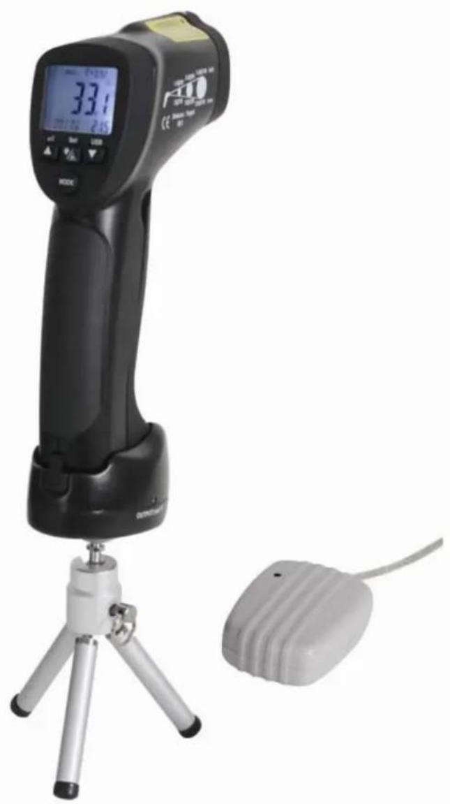
HIGH TEMPERATURE INFRARED & K-TYPE THERMOCOUPLE THERMOMETER THERMOMETER VOOR HOGE TEMPERATURE - IR + THERMOKOPPEL TYPE K THERMOMÉTRE POUR HAUTES TEMPERATURES - IR+ THERMOCOUPLE TYPE K THERMOMETER FÜR HOHE TEMPERATURE - INFRAROT + K-TYP-FUHLER TERMÖMETRO PARA ALTAS TEMPERATURES - IR + TERMOPART TIPO "K"
USER MANUAL 3
GEBRUIKERSHANDLEIDING 12
NOTICE D'EMPLOI 21
MANUAL DEL USUARIO 30
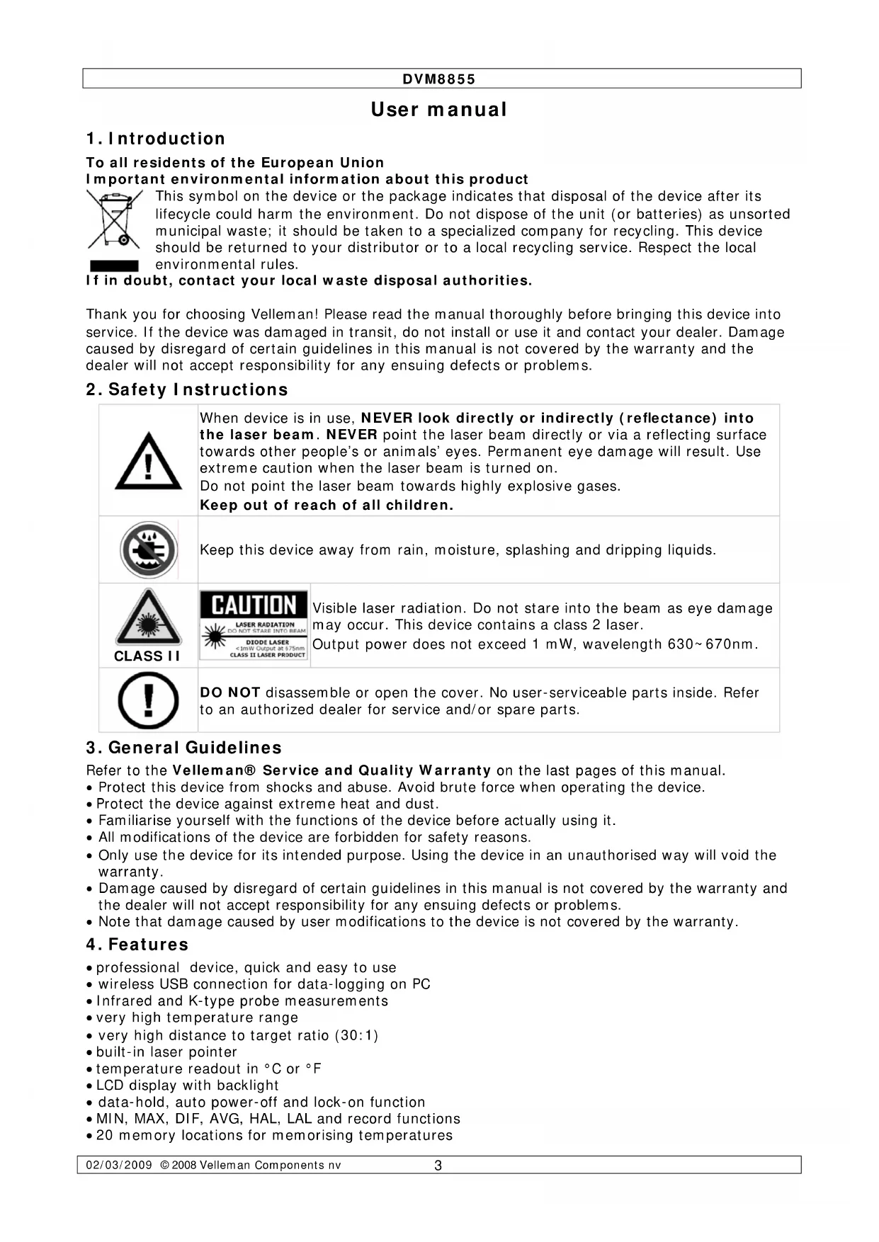
To all residents of the European Union
Important environmental information about this product
This symbol on the device or the package indicates that disposal of the device after its lifecycle could harm the environment. Do not dispose of the unit (or batteries) as unsorted municipal waste; it should be taken to a specialized company for recycling. This device should be returned to your distributor or to a local recycling service. Respect the local environmental rules.
If in doubt, contact your local waste disposal authorities.
Thank you for choosing Velleman! Please read the manual thoroughly before bringing this device into service. If the device was damaged in transit, do not install or use it and contact your dealer. Damage caused by disregard of certain guidelines in this manual is not covered by the warranty and the dealer will not accept responsibility for any ensuing defects or problems.
2. Safety Instructions

When device is in use, NEVER look directly or indirectly (reflectance) into the laser beam. NEVER point the laser beam directly or via a reflecting surface towards other people's or animals' eyes. Permanent eye damage will result. Use extreme caution when the laser beam is turned on.
Do not point the laser beam towards highly explosive gases.
Keep out of reach of all children.

Keep this device away from rain, moisture, splashing and dripping liquids.
DIODE LASERCLASS II LASER PRODUCT
Visible laser radiation. Do not stare into the beam as eye damage may occur. This device contains a class 2 laser.
Output power does not exceed 1mW wavelength 630 670nm

CLASS II
DO NOT disassemble or open the cover. No user-serviceable parts inside. Refer to an authorized dealer for service and/or spare parts.
3. General Guidelines
Refer to the Velleman® Service and Quality Warranty on the last pages of this manual.
- Protect this device from shocks and abuse. Avoid brute force when operating the device.
- Protect the device against extreme heat and dust.
- Familiarise yourself with the functions of the device before actually using it.
- All modifications of the device are forbidden for safety reasons.
- Only use the device for its intended purpose. Using the device in an unauthorised way will void the warranty.
- Damage caused by disregard of certain guidelines in this manual is not covered by the warranty and the dealer will not accept responsibility for any ensuing defects or problems.
Note that damage caused by user modifications to the device is not covered by the warranty.
4. Features
- professional device, quick and easy to use
- wireless USB connection for data-logging on PC
- Infrared and K-type probe measurements
- very high temperature range
- very high distance to target ratio (30:1)
- built-in laser pointer
- temperature readout in ^ C or ^ F
- LCD display with backlight
- data-hold, auto power-off and lock-on function
MIN, MAX, DIF, AVG, HAL, LAL and record functions - 20 memory locations for memorising temperatures
DVM8855
- 1mV / ^ F (1.8mV/°C) analogue output
- adjustable emissivity
high and low alarm - contents: manual, tripod, K-type thermocouple, wireless USB receiver, wireless USB transmitter, software, power supply, connection lead for mV output, carrying case
5. Overview
Refer to the drawings on page 2 of this manual.
| 1 | IR sensor 6 mode button | ||
| 2 | laser pointer beam 7 laser/backlight button | ||
| 3 | LCD display 8 measurement trigger | ||
| 4 | down button 9 grip | ||
| 5 | up button | 10 | battery cover |
| display | F | °C or °F indication | |
| A | scan indication | G | low battery indication |
| B | hold indication | H | MAX, MIN, DIF, AVG, HAL, LAL, Tk and memory values |
| C | auto emissivity | I | high and low alarm indication |
| D | emissivity indication and value | J | indication for H |
| E | lock and laser ON indication | K | current measurement value |
| inside battery compartment | M | lock on/off switch | |
| L | °C and °F switch | N | alarm set switch |
6. Operation
- Hold the thermometer by the grip [9] and point the IR sensor [1] towards the surface of which the temperature needs to be measured.
- Pull and hold the measurement trigger [8]. The LCD display [3] shows the current temperature [K].
- During measurement, the word 'SCAN' [A] is visible in the LED display. When the measurement stops (trigger [8] released), the word 'HOLD' [B] is shown. The last measured value will remain on the display until the measurement trigger [8] is pulled again, or when the thermometer powers-off automatically (after ± 7 seconds).
- Depending on the mode, the bottom of the screen shows the MAX, MIN, DIF, AVH, HAL, LAL Tk or memory values. Use the mode button [6] to scroll through the modes of the device. The mode [J] and corresponding value [H] are shown on the display.
| MODE | ||||||||
| EMS MAX MIN DIF AVG HAL LAL Tk LOG# | ||||||||
| EMS Emissivity (*) | ||||||||
| MAX | Highest measured value | |||||||
| MIN Lowest measured value | ||||||||
| DIF | Difference between the highest and lowest measured value | |||||||
| AVG Average value of the temperature | ||||||||
| HAL | Higher alarm limit | |||||||
| LAL | Lower alarm limit | |||||||
| Tk | Temperature measured via thermocouple | |||||||
| LOG # | Show memory location number # (max. 20) value | |||||||
(*)For more information on emissivity, refer to §8 Useful information.
- To set EMS, HAL or LAL, use the up [5] or down [4] button to adjust the value and press the mode button [6] again to save the value and go to the next item. To cancel mode selection, pull the measurement trigger [8]. Pushing the mode button [6] after setting the lower alarm limit will start the set-up cycle again.
- Note that MAX, MIN, DIF and AVG only apply to the current measuring session (time between pulling the trigger [8] and releasing it). Their value is reset when a new measurement starts or the thermometer switches off.
- To switch between measurements in ^ C and ^ F , open the battery cover [10]. The battery cover has a hinge at the bottom of the device. Hold the battery cover at the top (next to the measurement trigger [8]) and gently pull away from the device.
DVM8855
- The ^ C / ^ F switch [L] is located inside the battery compartment under the battery. Move this switch to the desired setting. The current setting is indicated [F] in the display.
- Also under the battery, there is a lock switch [M]. Move this switch to the ON-position for continuous measurement. The current setting is indicated with a lock symbol [E] in the display. Start measuring by pulling the measurement trigger [8] once. Consider disabling the laser targeting beam in continuous measuring mode to save battery power. To stop and disable lock mode, set the switch [M] back to the OFF-position. In lock mode, it is still possible to adjust EMS, HAL and LAL values.
- The third switch under the battery is the alarm set switch [N]. Move this switch to the ON-position to enable alarm warnings when high or low alarm limits are exceeded. When enabled, a Hi- and LOW indication [I] are shown on the display.
- Close the battery cover [10] by pushing it back towards the device until it snaps in place.
- When the measured value exceeds a preset alarm limit, an audible alarm signal will be produced (when the alarm set switch [N] is set to ON), and the according alarm icon in the display [I] will flash. Alarm will stop when temperature is back within preset limits.
- Push the laser/backlight button [7] to cycle through the laser and backlight options (not available in memory mode (LOG # displayed)). Note that the laser beam is only an aiming aid, be careful when using it. Refer to the safety instructions.
| Push | result |
| 1 | backlight on |
| 2 | backlight on and laser enabled |
| 3 | backlight off and laser enabled |
| 4 | backlight off and laser disabled |
- To measure temperatures using the thermocouple, first connect the thermocouple to the bottom of the grip [9]. The connector is slotted and can be inserted only one way. Do not force. Use the mode button [6] to go to Tk mode [J] and read the thermocouple temperature [H].
- The DVM8855 has 20 memory locations to store measurements. Use the mode button [6] to go to LOG mode [J] and use the up [5] or down [4] button to scroll through the memory. To store a measured value, go to the desired memory location and press the laser/backlight button [7].
Emissivity measurement
- To determine the emissivity of a surface, go to EMS mode using the mode button [6]. Connect the thermocouple and attach it to the surface. Pull and hold the measurement trigger [8] (consider placing the meter in lock mode [M]). Press and hold the laser/backlight button [7] until the EMS indication [J] starts flashing and the thermocouple measured value is shown [H]. Point the IR sensor [1] towards the surface, close to the location of the thermocouple. When Tk and IR measurements are identical and stable, press the up [5] or down [4] button. The measured emissivity [C] is indicated [D] and normal measurement can be resumed.
Notes on emissivity measurement:
- Allow at least 15min for the thermocouple to reach the surface temperature.
- The measuring surface should be higher in temperature than the environment, e.g. 100^ surface temperature will provide a more accurate measurement of the emissivity.
- When the temperature measured with the thermocouple differs from the one measured with the IR sensor, or measuring points differ, the obtained emissivity will be wrong, or ERR is displayed.
- To exit emissivity measurement at any time, press the mode button [6].
General remarks:
- The device powers off automatically (after ± 7 seconds) when no activity is detected, unless it is in lock mode.
- The unit will not measure correctly through transparent surfaces (e.g. glass), as it will measure the surface temperature of the transparent surface.
- Steam, dust, smoke etc. will have a negative impact on the measurements accuracy.
- Measurements on shiny and/or polished surfaces are not recommended.
- To use the tripod, first plug the DVM8855 in the transmitter stand. Place the connector pins at the front of grip [9] first, then tilt down until the meter snaps in place. To remove, lift the back up first. Screw the tripod into the bottom of the transmitter stand and extend the legs of the tripod to set the preferred height. Position the head and use the screw on the side to secure it.
7. Software installation and use
Driver installation
- Plug the USB connector of the receiver into a free powered USB port of a PC. The system should recognize the new hardware automatically: CP2102 USB to UART Bridge Controller.
The Found New Hardware Wizard' pops up:
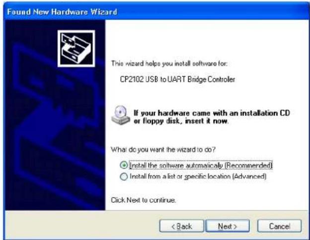
- Select 'Install the software automatically (Recommended)' option and click 'Next >'.
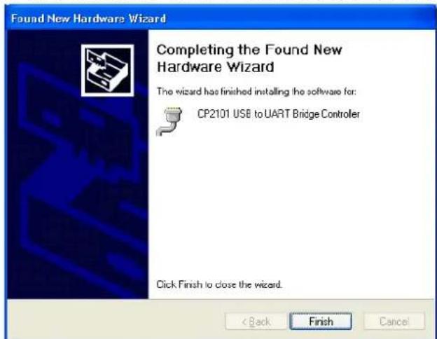
- The 'Completing the Found New Hardware Wizard' window pops up. Click on 'Finish'.
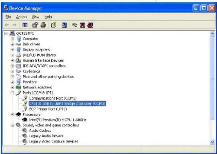
- Verify the driver installation in the Device manager. Go to 'My computer' - 'System information' - tab 'Hardware' and click on 'Device Manager'. Look for 'CP2102 USB to UART Bridge Controller' under section 'Ports (COM & LPT)'. A COM-port was assigned to this bridge controller; it is mentioned between brackets at the end of the line. Remember this number as it is needed to configure the software. Double click (left) on the device name to see more details.
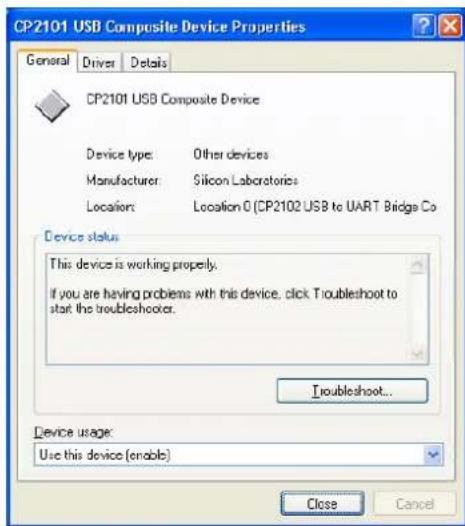
DVM8855
- If the driver is not installed correctly, device manager shows a yellow exclamation mark in front of the device name.
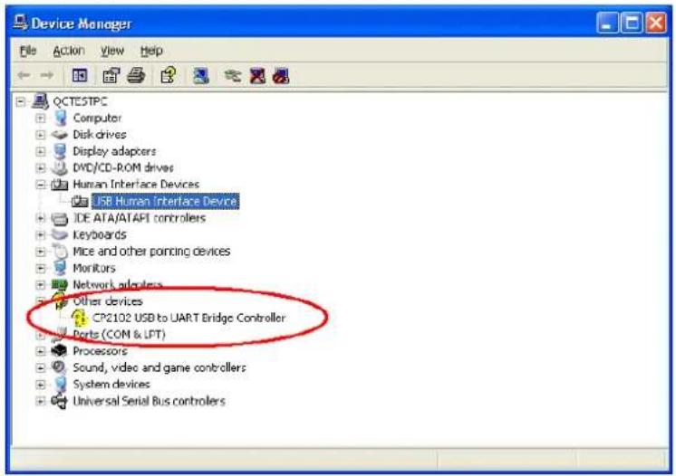
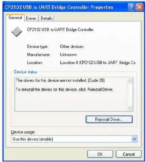
- Double click (left) on the device name and click on 'Reinstall Driver...' or go to the 'Driver'-tab to uninstall the driver. The driver can be found on the included CD-ROM (CP2101WIN under DT-8855).
Software installation
- Insert the included CD-ROM into the CD-drive of the PC. Locate the file 'DT8855.exe' under the 'DT-8855' directory and double click (left) on it to start the installation.
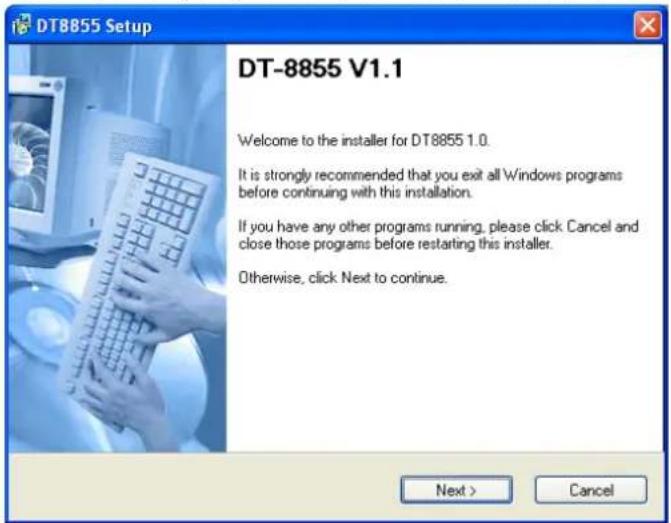
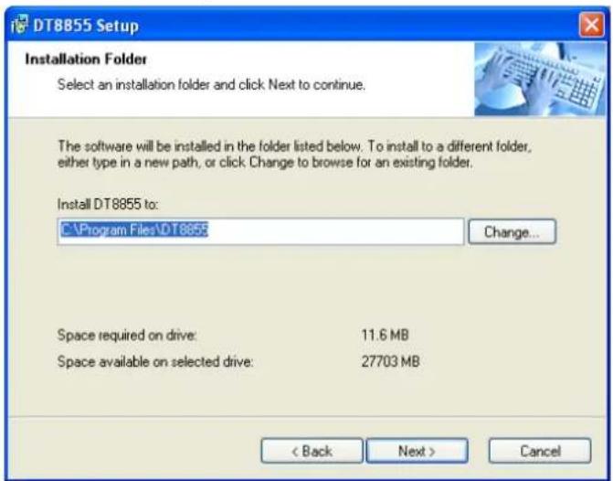
- Click on 'Next >' and in the next screen, choose a destination folder for the software.
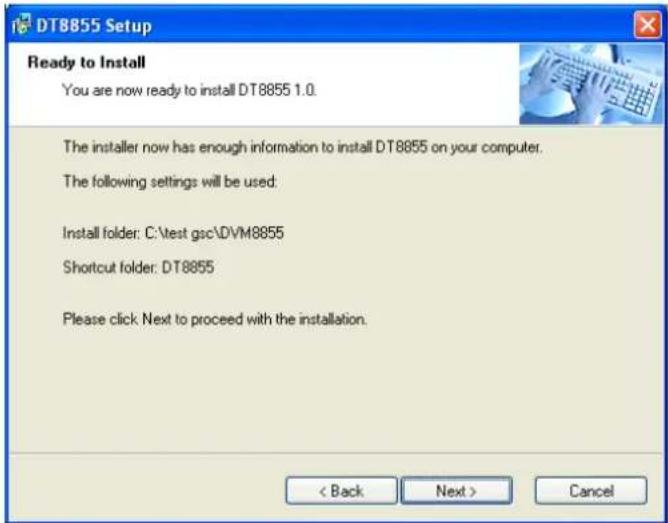
- In the following screen, click 'Next >'.
DVM8855
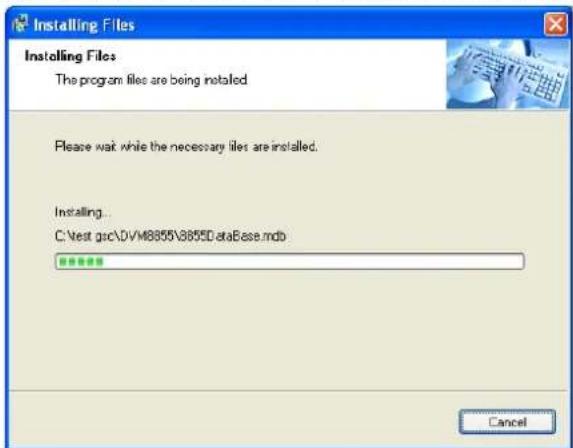
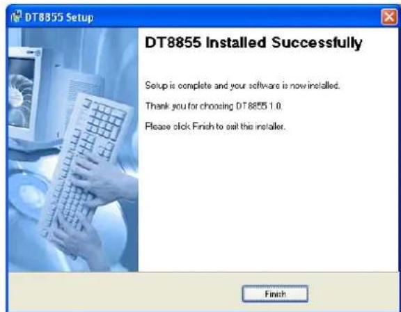
- An installation progress screen is shown, followed by the 'DT8855 Installed Successfully' screen. Click 'Finish' to finalize the software installation.
Software description
- Locate the file 'DT-8855.exe' in the folder where the software was installed and double click (left) on it. The application opens.
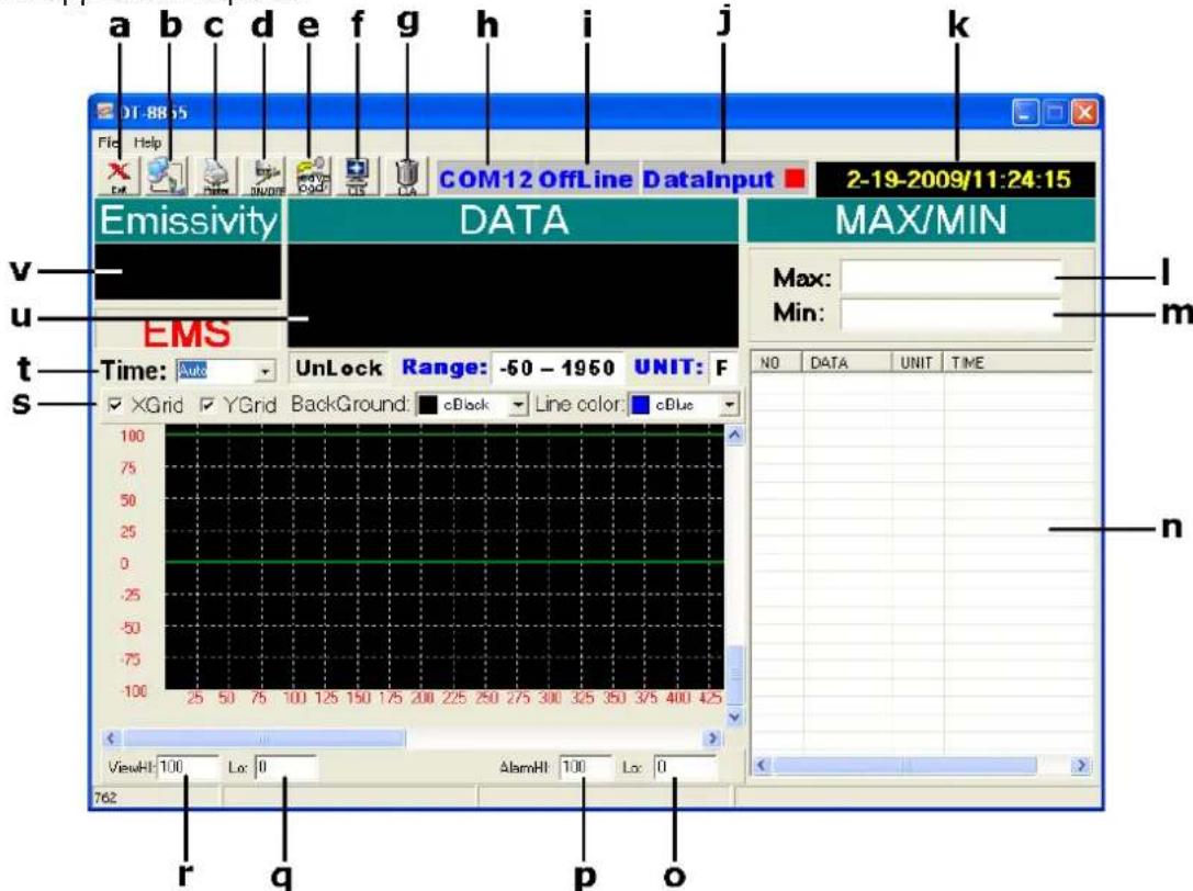
| a | exit the application | l | max. measured temperature |
| b | select com port | m | min. measured temperature |
| c | print data | n | data window |
| d | switch between online and offline | o | lower alarm limit |
| e | save/load data | p | higher alarm limit |
| f | clear graph | q | set lower range graph |
| g | clear all data | r | set higher range graph |
| h | current COM port | s | graph display setup |
| i | status (OnLine = connected) | t | set sampling time |
| j | data input (red = receiving) | u | current temperature |
| k | current date and time | v | current emissivity setting |
Using the wireless link
Note: connection can only be established when the thermometer is in scan mode. Consider placing the meter in lock mode [M] for easy handling.
- Make sure the USB connector of the receiver is plugged into the PC. The red status LED on the receiver lights up.
- Plug the DVM8855 in the transmitter stand. Place the connector pins at the front of grip [9] first, than tilt down until the meter snaps in place. To remove, lift the back up first.
- Connect the DC connector of the included power adaptor into the transmitter stand and plug the other end into the mains (100~240CAC, 50~60Hz).
- Start the DT-8855 software and set the correct com port [b], most likely this will be COM3 (verify with 'device manager').
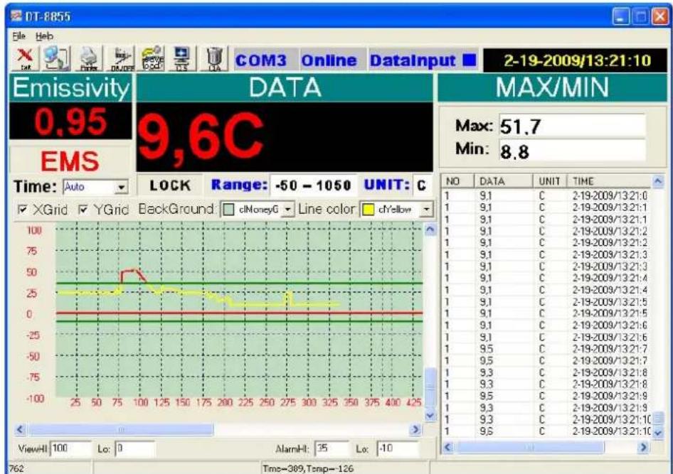
- Press the 'ON'-button on the transmitter stand and press the online button [d]. When the thermometer is in SCAN mode, the status LEDs of both transmitter and receiver start blinking in sync, indicating there is communication. Data will be shown in the data window [n].
- Setup the software as desired. Set the sample time [t], this is the time the software waits between 2 interrogations of the thermometer. Set the lower [o] and higher [p] time limits. These are indicated by a horizontal line on the selected temperature. When the temperature crosses these lines, the graph will turn red (see example below).
- The measured data can be saved and recalled [e]. The file format is .xls (Excel). Data which is not saved prior to closing the application is lost.
- Note that the transmitter stand also has an analogue output which can be connected to a plotter (not incl.) or similar device. Signal scale is 1mV / ^ (± 1.8mV / ^)
8. Useful information
Working principle
The Infra Red sensor of the unit detects energy that is emitted, reflected and transmitted by a surface. This energy is focussed onto a detector that converts this information into a temperature reading. The laser beam is only used for aiming purposes.
Ambient temperature
The thermometer automatically compensates ambient temperature conditions. Allow the thermometer to stabilise to ambient temperature for at least 30 minutes for accurate measurements.
Surface temperature
When going from low temperature to high temperature measurements or vice versa, the IR sensor of the thermometer needs a few minutes to adjust.
Distance and spot size
Refer to the drawing on page 2 of this manual.
As the distance (D) from the object increases, the spot size (S) of the area measured by the unit becomes larger. The focal point for this unit is 914mm (36"). Note that the laser beam points 16mm above the measurement centre point.
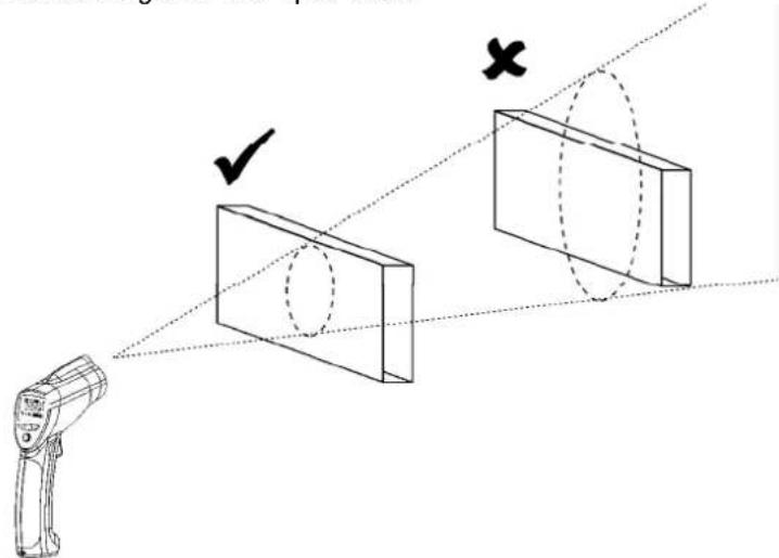
Field of view
The target must be larger than the spot size to ensure correct measurement. This means that for smaller targets, the thermometer must be held closer to the target. For best accuracy, make sure the target is at least twice as large as the spot size.
Emissivity
Emissivity describes the energy-emitting characteristics of materials. Most organic or oxidized surfaces have an emissivity of ± 0.95 (default setting). Measuring shiny or polished surfaces will be inaccurate. Use some masking tape or paint to compensate, allow sufficient time for the tape or paint to reach the surface temperature.
| Substance | Emissivity | Substance | Emissivity |
| Asphalt 0.90 to 0.98 Cloth (black) | 0.98 | ||
| Concrete | 0.94 | Human skin | 0.98 |
| Cement 0.96 Leather | 0.95 to 1.00 | ||
| Sand | 0.90 | Charcoal (powder) | 0.96 |
| Earth | 0.92 to 0.96 Lacquer | 0.80 to 0.95 | |
| Water | 0.92 to 0.96 | Lacquer (matt) | 0.97 |
| Ice | 0.96 to 0.98 Rubber (black) | 0.94 | |
| Snow | 0.83 | Plastic | 0.85 to 0.95 |
| Glass | 0.90 to 0.95 Timber | 0.90 | |
| Ceramic | 0.90 to 0.94 | Paper | 0.70 to 0.94 |
| Marble | 0.94 Chromium oxides | 0.81 | |
| Plaster | 0.80 to 0.90 | Copper oxides | 0.78 |
| Mortar | 0.89 to 0.91 Iron | oxides 0.78 to 0.82 | |
| Brick | 0.93 to 0.96 | Textiles | 0.90 |
9. Cleaning and storage
- The IR sensor [1] is the most delicate part of the thermometer and should be kept clean at all times. To do this, only use a soft cloth or cotton bud. Do not use excessive pressure on the sensor.
- Wipe the other parts of the thermometer regularly with a dry cloth. Do not use abrasive solutions or solvents.
- Do not submerge the thermometer in water or any other liquid.
- There are no user-serviceable parts. Contact your dealer for spare parts if necessary.
- The device must be stored in a place with temperature conditions between -20^ and +60^ (-4°F and +140°F) and relative humidity lower than 80%.
10. Battery
- When the battery indicator [G] indicates low battery, replace the battery with a new one.
- Open the battery cover [10]. The battery cover has a hinge at the bottom of the device. Hold the battery cover at the top (next to the measurement trigger [8]) and gently pull away from the device.
- If necessary switch the lock switch [L] to the OFF-position first.
- Connect a new 9V battery to the thermometer with the battery clip and insert the battery in the battery compartment.
- Push the cover back towards the device until it snaps into place.

WARNING: malfunction may occur if the power is on when the battery is replaced. Do not attempt to recharge non-rechargeable batteries, do not puncture or do not throw batteries in fire as they might explode. Dispose of batteries in accordance with local regulations.
Keep the battery away from children.
11. Technical specifications
| measurement range | infrared -50°C ~ + | 1050°C (-58°F ~ + 1922°F) | |
| K-type probe -50°C ~ + | 1370°C (-58°F ~ + 1999°F) | ||
| accuracy K-type probe (Tamb= 25°C) | Tobj = -50°C ~ 1000°C ± | 1.5% of rdg ± 3°C (5.4°F) | |
| accuracy IR (Tamb= 25°C) | Tobj = -20°C ~ 200°C (-4°F ~ 392°F) | ± 1.5% of rdg ± 2°C (3.6°F) | |
| Tobj = 200°C ~ 538°C (392°F ~ 1000°F) | ± 2.0% of rdg ± 2°C (3.6°F) | ||
| Tobj = 538°C ~ 1050°C (1000°F ~ 1922°F) | ± 3.5% of rdg ± 5°C (9°F) | ||
| response time < 1 sec | |||
| emissivity range 0.1 ~ 1.0 adjustable | |||
| wireless USB link | frequency | 433MHz | |
| range | 10m | ||
| wavelength 8μm - 14μm | |||
| distance-to-spot ratio D/S = 30:1 | |||
| power supply 1x 9V E-block battery (6F22C, incl.) | |||
| dimensions 100 x 56 x 230mm | |||
| weight | 290g | ||
Use this device with original accessories only. Velleman nv cannot be held responsible in the event of damage or injury resulted from (incorrect) use of this device.
For more info concerning this product, please visit our website www.velleman.eu.
The information in this manual is subject to change without prior notice.
COPYRIGHT NOTICE
The copyright to this manual is owned by Velleman Components nv. All worldwide rights reserved.
No part of this manual or the described software may be copied, reproduced, translated or reduced to any electronic medium or otherwise without the prior written consent of the copyright holder.
Velleman® Service and Quality Warranty
Vellemand® has over 35 years of experience in the electronics world and distributes its products in more than 85 countries.
All our products fulfil strict quality requirements and legal stipulations in the EU. In order to ensure the quality, our products regularly go through an extra quality check, both by an internal quality department and by specialized external organisations. If, all precautionary measures notwithstanding, problems should occur, please make appeal to our warranty (see guarantee conditions).
General Warranty Conditions Concerning Consumer Products (for EU):
-
All consumer products are subject to a 24-month warranty on production flaws and defective material as from the original date of purchase.
-
Velleman® can decide to replace an article with an equivalent article, or to refund the retail value totally or partially when the complaint is valid and a free repair or replacement of the article is impossible, or if the expenses are out of proportion.
You will be delivered a replacing article or a refund at the value of 100% of the purchase price in case of a flaw occurred in the first year after the date of purchase and delivery, or a replacing article at 50% of the purchase price or a refund at the value of 50% of the retail value in case of a flaw occurred in the second year after the date of purchase and delivery.
Not covered by warranty:
-
all direct or indirect damage caused after delivery to the article (e.g. by oxidation, shocks, falls, dust, dirt, humidity...), and by the article, as well as its contents (e.g. data loss), compensation for loss of profits:
-
frequently replaced consumable goods, parts or accessories such as batteries, lamps, rubber parts, drive belts... (unlimited list);
-
flaws resulting from fire, water damage, lightning, accident, natural disaster, etc. ...
-
flaws caused deliberately, negligently or resulting from improper handling, negligent maintenance, abusive use or use contrary to the manufacturer's instructions;
-
damage caused by a commercial, professional or collective use of the article (the warranty validity will be reduced to six (6) months when the article is used professionally);
-
damage resulting from an inappropriate packing and shipping of the article;
-
all damage caused by modification, repair or alteration performed by a third party without written permission by Velleman®.
-
Articles to be repaired must be delivered to your Velleman® dealer, solidly packed (preferably in the original packaging), and be completed with the original receipt of purchase and a clear flaw description.
-
Hint: In order to save on cost and time, please reread the manual and check if the flaw is caused by obvious causes prior to presenting the article for repair. Note that returning a non-defective article can also involve handling costs.
-
Repairs occurring after warranty expiration are subject to shipping costs.
-
The above conditions are without prejudice to all commercial warranties.
The above enumeration is subject to modification according to the article (see article's manual).
NL
- To all residents of the European Union
- Safety Instructions
- General Guidelines
- Features
- DVM8855
- Overview
- Operation
- Emissivity measurement
- General remarks:
- Software installation and use
- Driver installation
- Software installation
- Software description
- Using the wireless link
- Useful information
- Working principle
- Ambient temperature
- Surface temperature
- Distance and spot size
- Field of view
- Emissivity
- Cleaning and storage
- Battery
- Technical specifications
- COPYRIGHT NOTICE
- Velleman® Service and Quality Warranty
- General Warranty Conditions Concerning Consumer Products (for EU):
- Not covered by warranty:
- The above enumeration is subject to modification according to the article (see article's manual).
- NL
Brand : VELLEMAN
Model : DVM8855
Category : Humidifier