CT7.4 LCRS - Speaker BOWERS & WILKINS - Free user manual and instructions
Find the device manual for free CT7.4 LCRS BOWERS & WILKINS in PDF.

Frequently Asked Questions - CT7.4 LCRS BOWERS & WILKINS
User questions about CT7.4 LCRS BOWERS & WILKINS
0 question about this device. Answer the ones you know or ask your own.
Ask a new question about this device
Download the instructions for your Speaker in PDF format for free! Find your manual CT7.4 LCRS - BOWERS & WILKINS and take your electronic device back in hand. On this page are published all the documents necessary for the use of your device. CT7.4 LCRS by BOWERS & WILKINS.
USER MANUAL CT7.4 LCRS BOWERS & WILKINS
natural_image
Close-up of a black speaker cone with mesh pattern and mounting holes (no text or symbols visible)Figure 1
text_image
0.5m (20 in) 0.5m (20 in)Figure 2
natural_image
Simple line drawing of a person sitting on a bench facing a wall-mounted device (no text or symbols)Figure 3
natural_image
Technical diagram showing a mechanical bracket with screw fasteners and a pencil inserted (no text or symbols)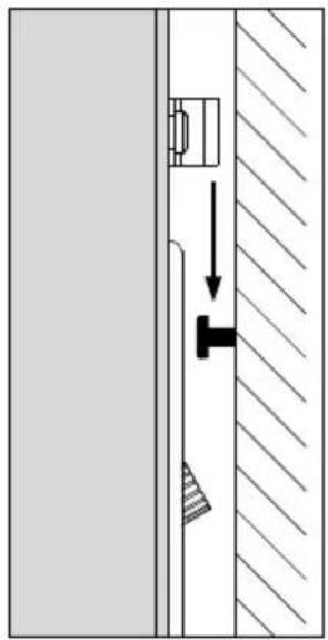
natural_image
Pure mechanical diagram showing a T-shaped component inserted into a wall, with no text or symbols present.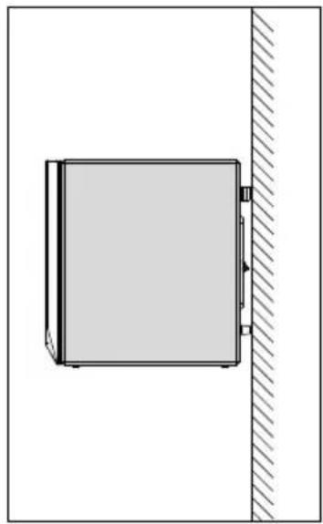
natural_image
Simple line drawing of a cabinet placed on a wall with a diagonal hatching (no text or symbols)Figure 4
natural_image
Diagram of a mechanical setup with a cylindrical component and two hanging pins, showing rotational motion (no text or symbols)Figure 5a
text_image
AMPLIFIER OUTPUTFigure 5b
text_image
Neutrik® Speakon® Connector NL2FC 1- 1+ AMPLIFIER OUTPUTFigure 6
Contents
English
Installation manual ......2
Limited Warranty......3
Français
Specifications .....42–44
English
Installation manual
Dear customer,
Thank you for choosing Bowers & Wilkins. Please read this manual fully before unpacking and installing the product. It will help you to optimise its performance. B&W maintains a network of dedicated distributors in over 60 countries who will be able to help you should you have any problems your dealer cannot resolve.
Environmental Information

All B&W products are designed to comply with international directives on the Restriction of Hazardous Substances (RoHS) in electrical and electronic equipment and the disposal of Waste Electrical and Electronic Equipment (WEEE). These symbols indicate compliance and that the products must be appropriately recycled or processed in accordance with these directives. Consult your local waste disposal authority for guidance.
Carton Contents
Check in the carton for:
4 Adhesive rubber feet
2 Adhesive rubber spacers
2 Port plugs
1 Speakon® plug
2 Wall brackets
4 M6 bolts
Speaker Installation
CT700 Series speakers can either be installed within existing or custom designed home theatre system cabinets, or wall mounted using a variety of brackets.
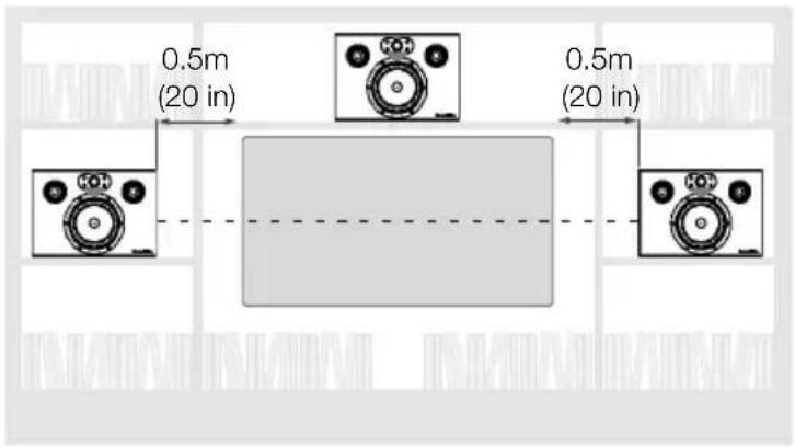
If the speakers are to be installed within a cabinet it is important to ensure that it is capable of carrying their weight and that it is structurally sound. Significant vibration of the cabinet panels may seriously affect the subjective performance of the speakers. Figure 1 illustrates the installation of three CT700 Series speakers in a home theatre cabinet showing the recommended dimensions between the speakers and space around them.
Adhesive rubber feet are supplied for attachment to the underside of the speakers in order both to protect the cabinet finish and to reduce vibration. Attach one adhesive foot at each underside corner of the speakers.
If gaps wider than approximately 20mm (3/4 inch) remain around a speaker when it has been installed in a cabinet, the acoustic performance will be improved if the gaps are filled. Use carefully cut pieces of upholstery or acoustic foam to fill the gaps as far back as is practical and flush with the front panel of the speaker. Only use foam with an appropriate fire safety rating.
CT700 Series speakers can also be wall mounted using one of two methods.
Wall Brackets:
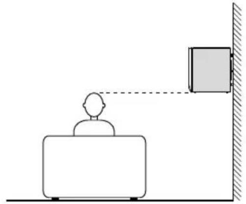
The speakers incorporate 4 M6 tapped inserts in their back panels for attachment of the two brackets supplied. Always use both brackets. Use the supplied M6 bolts to attach the brackets to the back of the speaker. The two supplied adhesive rubber spacers can be used to cushion the speaker against the wall. Figure 3 illustrates use of the brackets. Before using the brackets ensure that the wall and fixings are capable of supporting the weight of the speaker. B&W can accept no liability for any failure of wall and/or fixings.
Ball-joint Brackets:
The speakers incorporate 4 M6 tapped inserts in their undersides that enable the speakers to be wall-mounted using adjustable ball-joint style mounting brackets designed for 127mm x 69.9mm (5 in x 2.75 in) mounting hole centres. Your dealer or local B&W distributor will be able to advise you on the selection of appropriate brackets.
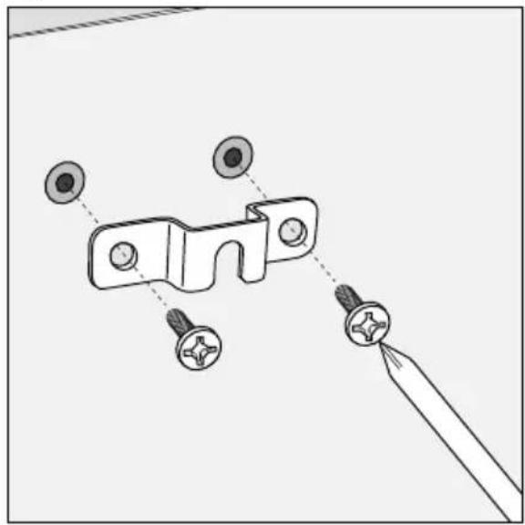
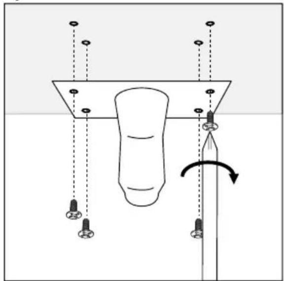
To attach a ball-joint style bracket to a CT700 Series speaker first securely attach the socket plate to the underside of the speaker. Figure 4 illustrates this procedure.
Once the socket plate is attached to the speaker, the assembly may be connected to the ball component attached to the wall. Ensure that the manufacturer's instructions for attaching the bracket to the wall are followed correctly and that the wall and fixings are capable of supporting the weight of the speaker. B&W can accept no liability for any failure of wall and/or fixings.
Regardless of the style of installation take care when lifting the speakers into position. They are unwieldy and heavy and best handled by two people working together.
The black fabric grilles are attached by magnets and may be removed if desired. Take care not to touch the drive units when removing or replacing the grilles.
Speaker Positioning
CT700 Series speakers used for the front left and right channels in a home theatre system should be positioned one either side of the screen on the horizontal centre-line. They should be within approximately 0.5m (20 in) of the sides of the screen to help keep the sound image in scale with the visual image. See Figures 1 and 2.
A CT700 Series speaker used for the centre channel in a home theatre system should be positioned centrally either directly above or below the screen. In the case of acoustically transparent screens, the centre channel speaker should be positioned centrally behind the screen.
CT700 Series speakers used for the surround channels in a home theatre system should be positioned above and to either side or behind the listening position.
Stray Magnetic Fields
The speaker drive units create stray magnetic fields that extend beyond the boundaries of the cabinet. We recommend you keep magnetically sensitive articles (CRT television and computer screens, computer discs, audio and video tapes, swipe cards and the like) at least 0.5m (20 in) from the speaker. LCD and plasma screens are not affected by magnetic fields.
Connections
All connections should be made with the equipment switched off.
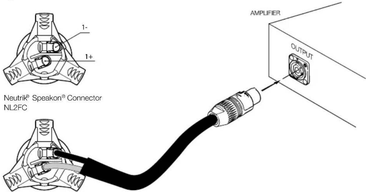
CT700 Series speakers have a pair binding post connection terminals and one Neutrik ^® Speakon ^® connection socket on their rear panels. The binding post terminals provide quick and easy connection of stripped wires while the Speakon socket provides a more secure and reliable connection method.
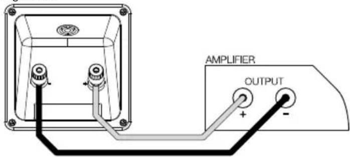
If the binding post terminals are to be used, connect the positive cable to the red terminal and the negative cable to the black terminal. Incorrect connection can result in poor imaging and loss of bass. Figure 5a illustrates use of the binding post terminals
If the Speakon ^® option is to be used, disassemble the Speakon ^® plug as shown in Figure 5b, connect the positive cable to the terminal marked +1 and the negative cable to the terminal marked -1. Incorrect connection can result in poor imaging and loss of bass. Once the plug is reassembled it can be inserted into the socket and locked by twisting clockwise.
Ask your dealer for advice when selecting speaker cable. Keep its total impedance below the maximum recommended in the speaker specification and use a low inductance cable to avoid attenuation of high frequencies.
Neutrik ^® and the names of Neutrik ^® products referenced herein are either trademarks and/or service marks of Neutrik ^® .
Fine Tuning
Before fine tuning, make sure that all the connections in the installation are correct and secure.
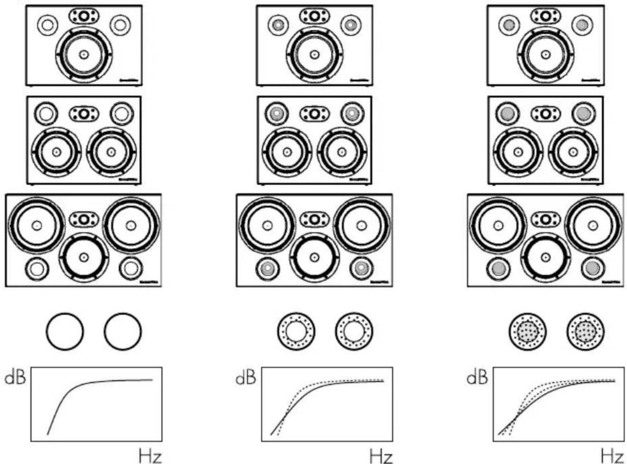
If the bass seems uneven with frequency this will most probably be due to resonance modes in the listening room. Even small changes in the listening position can have a profound effect on how these resonances affect the sound. Try moving the listening position. The presence and position of large pieces of furniture can also influence resonance modes. If you want generally to reduce the volume of bass fit the foam plugs in the speakers' port tubes as illustrated in Figure 6.
If the sound is too bright, increasing the amount of soft furnishing in the room (heavier curtains for example) may help balance the sound. Conversely, reducing the amount of soft furnishing may help brighten a dull sound.
Some rooms suffer from “flutter echoes” – echoes that “bounce” between parallel room boundaries. Flutter echoes can colour the sound of the speakers in the room. Test for flutter echoes by standing in the middle of the room and clapping your hands. Flutter echoes can be reduced by placing irregular shaped items or non-reflective surfaces, bookshelves, rugs or pictures for example, on one of the offending walls or floor.
Running-in Period
The performance of the speaker will change subtly during the initial listening period. If the speaker has been stored in a cold environment, the damping compounds and suspension materials of the drive units will take some time to recover their correct mechanical properties. The drive unit suspensions will also loosen up during the first hours of use. The time taken for the speaker to achieve its intended performance will vary depending on previous storage conditions and how it is used. As a guide, allow up to a week for the temperature effects to stabilise and 15 hours of average use for the mechanical parts to attain their intended design characteristics.
However, longer run-in periods (as long as a month) have been reported and there is evidence to suggest that this has little to do with the speaker changing and more to do with the listener getting used to the new sound. This is especially so with highly revealing speakers such as these where there may be a significant increase in the amount of detail compared with what the listener has previously been used to; the sound may at first appear too “up front” and perhaps a little hard. After an extended period of time the sound will seem to mellow, but without losing clarity and detail.
Aftercare
The cabinet surfaces usually only require dusting. If you wish to use an aerosol or other cleaner, remove the grille first by gently pulling it away from the cabinet. Spray aerosols onto the cleaning cloth, not directly onto the product. Test a small area first, as some cleaning products may damage some of the surfaces. Avoid products that are abrasive, or contain acid, alkali or anti-bacterial agents. Do not use cleaning agents on the drive units. The grille fabric may be cleaned with a normal clothes brush whilst the grille is detached from the cabinet. Avoid touching the drive units, especially the tweeter, as damage may result.
Limited Warranty
This product has been designed and manufactured to the highest quality standards. However, if something does go wrong with this product, B&W Group Ltd. and its national distributors warrant free of charge labour (exclusion may apply) and replacement parts in any country served by an official B&W distributor.
This limited warranty is valid for a period of five years from the date of purchase or two years for electronics including amplified loudspeakers.
Terms and Conditions
1 The warranty is limited to the repair of the equipment. Neither transportation, nor any other costs, nor any risk for removal, transportation and installation of products is covered by this warranty.
2 This warranty is only valid for the original owner. It is not transferable.
3 This warranty will not be applicable in cases other than defects in materials and/or workmanship at the time of purchase and will not be applicable:
a. for damages caused by incorrect installation, connection or packing,
b. for damages caused by any use other than correct use described in the user manual, negligence, modifications, or use of parts that are not made or authorised by B&W,
c. for damages caused by faulty or unsuitable ancillary equipment,
d. for damages caused by accidents, lightning, water, fire heat, war, public disturbances or any other cause beyond the reasonable control of B&W and its appointed distributors,
e. for products whose serial number has been altered, deleted, removed or made illegible,
f. if repairs or modifications have been executed by an unauthorised person.
4 This guarantee complements any national/regional law obligations of dealers or national distributors and does not affect your statutory rights as a customer.
How to claim repairs under warranty
Should service be required, please follow the following procedure:
1 If the equipment is being used in the country of purchase, you should contact the B&W authorised dealer from whom the equipment was purchased.
2 If the equipment is being used outside the country of purchase, you should contact the B&W national distributor in the country of residence who will advise where the equipment can be serviced. You can call B&W in the UK or visit our web site to get the contact details of your local distributor.
To validate your warranty, you will need to produce the warranty booklet completed and stamped by your dealer on the date of purchase. Alternatively, you will need the original sales invoice or other proof of ownership and date of purchase.
Français
EU DECLARATION OF CONFORMITY
We,
B&W Group Ltd.
whose registered office is situated at
Dale Road, Worthing, West Sussex, BN11 2BH, United Kingdom
declare under our sole responsibility that the products:
CT7.3 LCRS
CT7.4 LCRS
CT7.5 LCRS
complies with the EU Electro-Magnetic Compatibility (EMC) Directive 89/336/EEC, in pursuance of which the following standards have been applied:
EN 61000-6-1 : 2001
EN 61000-6-3:2001
EN 55020:2002
EN 55013:2001
and complies with the EU General Product Safety 2001/95/EC, in pursuance of which the following standard has been applied:
EN 60065:2002
This declaration attests that the manufacturing process quality control and product documentation accord with the need to assure continued compliance.
The attention of the user is drawn to any special measures regarding the use of this equipment that may be detailed in the owner's manual.
Signed:

text_image
Handwritten signature or scribble on a line drawing, possibly from a document or formG Edwards
Executive Vice President, Operations
B&W Group Ltd.
CT7.3
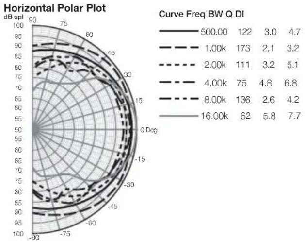
radar
| Curve Freq BW Q DI | 500.00 | 1.00k | 2.00k | 4.00k | 8.00k | 16.00k | | ------------------ | ------ | ----- | ----- | ----- | ----- | ------ | | 500.00 | 122 | 173 | 111 | 75 | 136 | 62 | | 1.00k | 3.0 | 2.1 | 3.2 | 4.8 | 2.6 | 5.8 | | 2.00k | 4.7 | 3.2 | 5.1 | 6.8 | 4.2 | 7.7 | | 4.00k | | | | | | | | 8.00k | | | | | | | | 16.00k | | | | | | |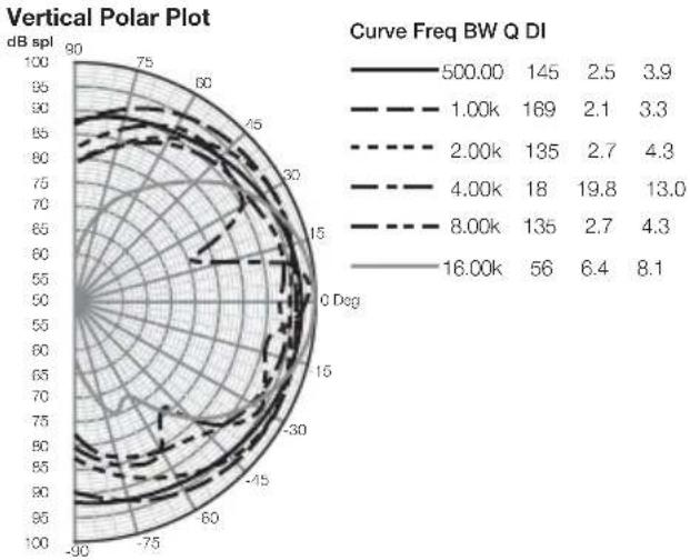
radar
| Curve Freq BW Q DI | 500.00 | 1.00k | 2.00k | 4.00k | 8.00k | 16.00k | | ------------------ | ------ | ----- | ----- | ----- | ----- | ------ | | Value | 145 | 169 | 135 | 18 | 135 | 56 | | Value | 2.5 | 2.1 | 2.7 | 19.8 | 2.7 | 6.4 | | Value | 3.9 | 3.3 | 4.3 | 13.0 | 4.3 | 8.1 |CT7.4
radar
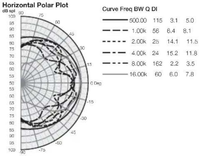
| Curve Freq BW Q DI | 500.00 | 1.00k | 2.00k | 4.00k | 8.00k | 16.00k | | ------------------ | ------ | ----- | ----- | ----- | ----- | ------ | | 500.00 | 115 | 56 | 25 | 24 | 162 | 60 | | 1.00k | 3.1 | 6.4 | 14.1 | 15.2 | 2.2 | 6.0 | | 2.00k | 8.1 | | | | | | | 4.00k | | | | | | | | 8.00k | | | | | | | | 16.00k | | | | | | |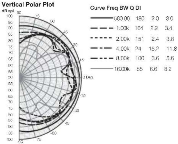
radar
| Curve Freq BW Q DI | 500.00 | 1.00k | 2.00k | 4.00k | 8.00k | 16.00k | | ------------------ | ------ | ----- | ----- | ----- | ----- | ------ | | Value | 180 | 164 | 151 | 24 | 100 | 55 | | Value | 2.0 | 2.2 | 2.4 | 15.2 | 3.6 | 6.6 | | Value | 3.0 | 3.4 | 3.8 | 11.8 | 5.6 | 8.2 |CT7.5
radar
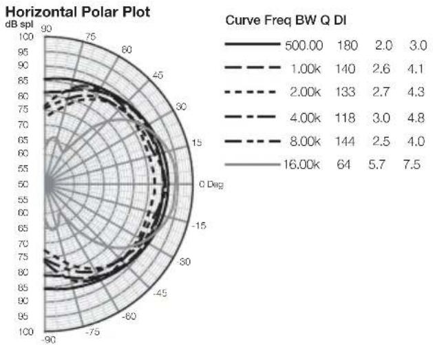
| Curve Freq BW Q DI | 500.00 | 1.00k | 2.00k | 4.00k | 8.00k | 16.00k | | ------------------ | ------ | ----- | ----- | ----- | ----- | ------ | | 500.00 | 180 | 140 | 133 | 118 | 144 | 64 | | 1.00k | 2.6 | 2.7 | 3.0 | 2.5 | 4.0 | 5.7 | | 2.00k | 4.1 | 4.3 | | | | | | 4.00k | | | | | | | | 8.00k | | | | | | | | 16.00k | | | | | | |
radar
| Curve Freq BW Q DI | 500.00 | 1.00k | 2.00k | 4.00k | 8.00k | 16.00k | | ------------------ | ------ | ----- | ----- | ----- | ----- | ------ | | 500.00 | 180 | 153 | 56 | 22 | 124 | 49 | | 1.00k | 2.4 | 6.4 | 16.5 | 2.9 | 4.6 | 7.3 | | 2.00k | 3.7 | 8.1 | | | | | | 4.00k | | | | | | | | 8.00k | | | | | | | | 16.00k | | | | | | |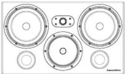
natural_image
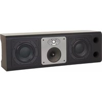
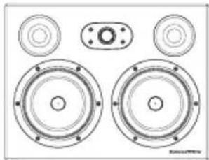
Technical line drawing of a multi-tiered speaker assembly with no text or symbolsCT7.3 LCRS
Technical features Nautilus ^™ tube-loaded tweeter
Kevlar ^® brand fibre cone FST ^™ midrange
Paper/Kevlar® brand cone bass driver
Flowport™
Magnetically attached grille
Description 3-way vented-box system
Drive units 1x ø25mm (1 in) cloth dome high-frequency
1x ø150mm (6 in) woven blue Kevlar® FST™ midrange
2x ø200mm (8 in) paper/Kevlar® bass units
Frequency range -6dB at 38Hz and 33kHz
Frequency response 49Hz - 28kHz ±3dB on reference axis
Dispersion Within 2dB of reference response
Horizontal: over 60° arc
Vertical: over 10° arc
Sensitivity 94dB spl (2.83V, 1m)
Harmonic distortion 2nd and 3rd harmonics (90dB, 1m)
<1% 50Hz - 20kHz
Nominal impedance 8Ω (minimum 3.0Ω)
Crossover frequencies 350Hz, 4kHz
Recommended amplifier power 50W - 200W into 8Ω on unclipped programme
Max. recommended cable impedance 0.1Ω
Dimensions Height: 360mm (14.2 in)
Width: 606mm (23.9 in)
Depth: 265mm (10.5 in) (including grille and terminals)
Depth with grille: 288mm (11.3 in)
Net weight 22.5kg (49.5 lb)
natural_image
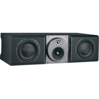
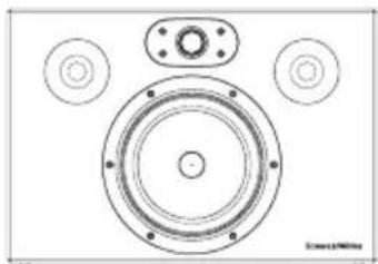
Technical line drawing of a speaker assembly with two main speakers and four circular components (no text or labels)CT7.4 LCRS
Technical features
Nautilus™ tube-loaded tweeter
Kevlar® brand fibre cone bass/midrange
Flowport™
Magnetically attached grille
Description
2-way vented-box system
Drive units
1x ø25mm (1 in) cloth dome high-frequency
2x ø165mm (6.5 in) woven Kevlar® cone bass/midrange
Frequency range
-6dB at 34Hz and 33kHz
Frequency response
49Hz - 28kHz ±3dB on reference axis
Dispersion
Within 2dB of reference response
Horizontal: over 60° arc
Vertical: over 10^ arc
Sensitivity
93dB spl (2.83V, 1m)
Harmonic distortion
2nd and 3rd harmonics (90dB, 1m)
<1% 90Hz - 20kHz
Nominal impedance
8Ω (minimum 4.0Ω)
Crossover frequency
4kHz
Recommended amplifier power
50W - 150W into 8Ω on unclipped programme
Max. recommended cable impedance
0.1Ω
Dimensions
Height: 343mm (13.5 in)
Width: 444mm (17.5 in)
Depth: 265mm (10.5 in)
Depth with grille: 288mm (11.3 in)
Net weight
16.5kg (36.3 lb)
natural_image
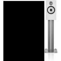
Technical line drawing of a speaker with concentric rings and mounting holes (no text or symbols)CT7.5 LCRS
Technical features
Nautilus ^™ tube-loaded tweeter Kevlar ^® brand fibre bass/midrange Flowport ^™ Magnetically attached grille
Description
2-way vented-box system
Drive units
1x ø25mm (1 in) cloth dome high-frequency 1x ø180mm (7 in) woven blue Kevlar® bass/midrange
Frequency range
-6dB at 50Hz and 33kHz
Frequency response
55Hz - 28kHz ±3dB on reference axis
Dispersion
Within 2dB of reference response Horizontal: over 60° arc Vertical: over 10° arc
Sensitivity
92dB spl (2.83V, 1m)
Harmonic distortion
2nd and 3rd harmonics (90dB, 1m) <1% 100Hz - 20kHz
Nominal impedance
8Ω (minimum 4.6Ω)
Crossover frequency
4kHz
Recommended amplifier power
50W - 120W into 8Ω on unclipped programme
Max. recommended cable impedance
0.1Ω
Dimensions
Height: 305mm (12 in) Width: 444mm (17.5 in) Depth: 265mm (10.5 in) Depth including grille: 288mm (11.3 in)
Net weight
11.5kg (25.3 lb)
Bowers & Wilkins
B&W Group Ltd.
Dale Road
Worthing West Sussex
BN11 2BH England
T +44 (0) 1903 221 800
F +44 (0) 1903 221 801
info@bwgroup.com
www.bowers-wilkins.com
B&W Group (UK Sales)
T +44 1903 221 500
E uksales@bwgroup.com
B&W Group North America
T +1 978 664 2870
E marketing@bwgroupusa.com
B&W Group Asia Ltd.
T +852 2 869 9916
E info@bwgroup.hk
Neutrik and Speakon are registered
trademarks of Neutrik AG.
Kevlar is a registered trademark of DuPont.
Nautilus is a trademark of B&W Group Ltd.
Copyright © B&W Group Ltd. E&OE
Printed in China.