CS200M - Scale Brecknell - Free user manual and instructions
Find the device manual for free CS200M Brecknell in PDF.

| Product Type | Mechanical Weighing Chair |
| Brand | Brecknell |
| Model | CS200M |
| Usage | Weighing of patients with reduced mobility in clinics |
| Frame Material | Robust enameled steel |
| Seat Material | Molded plastic |
| Footrest | Very robust, removable |
| Wheels | Swivel casters with locking device |
| Carrying Handle | Yes |
| Armrests | Removable, liftable and lowerable |
| Maximum Capacity | 200 kg |
| Power Supply | Mechanical (no electrical power) |
| Main Functions | Mechanical weighing, zero adjustment |
| Maintenance and Cleaning | Clean with a soft, non-abrasive cloth |
| Safety | Lockable wheels, safety armrests |
| Spare Parts and Repairability | Contact Brecknell |
| General Information | User manual available online |
Frequently Asked Questions - CS200M Brecknell
User questions about CS200M Brecknell
0 question about this device. Answer the ones you know or ask your own.
Ask a new question about this device
Download the instructions for your Scale in PDF format for free! Find your manual CS200M - Brecknell and take your electronic device back in hand. On this page are published all the documents necessary for the use of your device. CS200M by Brecknell.
USER MANUAL CS200M Brecknell
CS-200M Mechanical Chair Scale
Installation & Operation Instructions
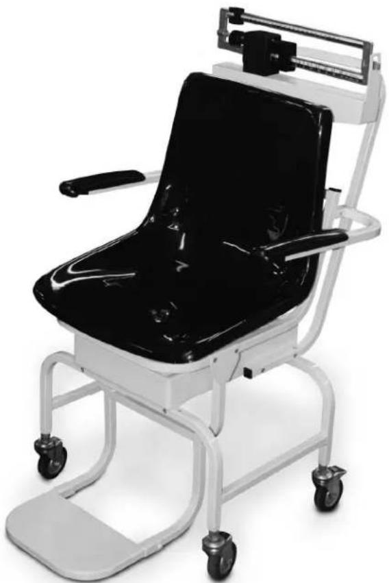
The CS-200M Mechanical Chair Sale is designed for the mobile challenged who have a difficult time standing on a conventional scale. It is ideal for use in clinics and nursing facilities. The scale is durable, having a sturdy enameled steel body, a durable molded plastic seat, heavy-duty footrest, and heavy-duty caster wheels for easy portability.
natural_image
Modern medical mobility chair with black seat and white frame, no visible text or symbolsFigure 1. Mechanical Chair Scale
Installation Instructions
You will receive your Mechanical Chair Scale partially assembled. Those items that need additional assembly are:
• Pillar and beam assembly to scale base
• Steelyard rod connection
• Transport handle onto scale base
- Seat and footrest installation
- Arm rest installation
Remove all components from the shipping crate and lay out in a convenient place.
Pillar and Beam Installation
The pillar and beam comes separate from the scale base and must be attached prior to use.
natural_image
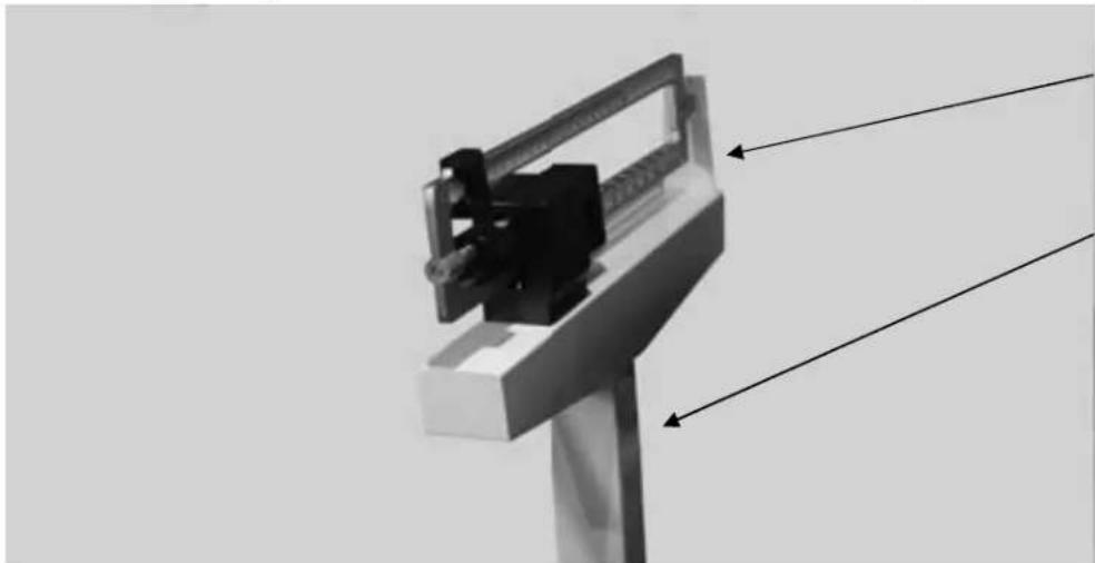
Mechanical device with lever and mounting bracket, no visible text or symbolsBeam
Pillar
Figure 2. Pillar and Beam Components
Use the following steps to attach the pillar and beam to the scale base.
- Have the scale sitting on the floor in an area that allows you to work freely.
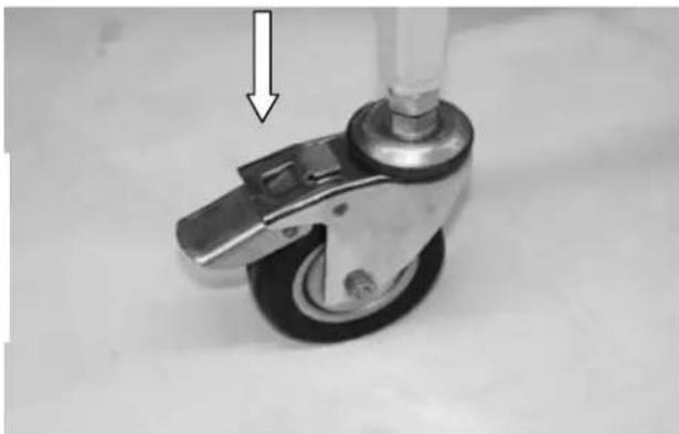
- Lock casters on the frame to eliminate the unit from rolling while assembling the scale.
Push down on latching assembly to lock wheels and prevent scale from rolling.
natural_image
Close-up of a mechanical control wheel with a vertical arrow pointing to the head (no text or symbols visible)Figure 3. Lock Casters to Keep From Rolling
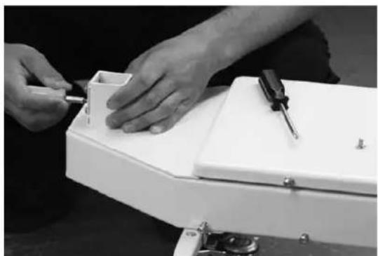
- Remove the eight screws from the scale base using a phillips head screwdriver (as shown in the left hand photo) and set screws aside in a safe place.
natural_image
Close-up of hands assembling a white electronic device with a screwdriver (no visible text or symbols)
natural_image
Close-up of a white metal bracket with mounting holes and structural details (no text or symbols visible)Figure 4. Remove Screws From Scale Base and Insert Pillar and Beam into Scale Base Assembly
Insert, but don't fasten the pillar and beam into the scale base assembly as shown in Figure 4 (right hand side photo).
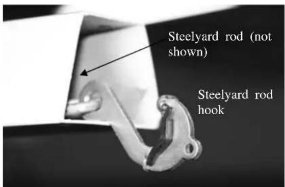
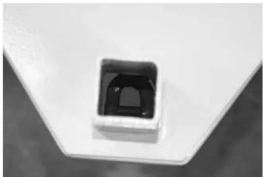
Steelyard Rod Connection
The steelyard rod is located inside the pillar. Remove the wire tie(s) holding the steelyard rod during shipment. Insert the pillar into the base. Once the pillar is inserted to the scale base, the steelyard rod must be attached to the bottom of the scale. The two photos below show the hook of the steelyard rod and an inside photo of the ring in the scale bottom. Latch the hook onto the D-shaped ring shown in the right hand side picture.
natural_image
Close-up of a small square electronic component with a black internal structure, mounted on a white base (no visible text or symbols)Figure 5. Attach The Steelyard Rod To the Scale Base D-Ring
Fasten the eight screws once the pillar and beam is connected to the scale base and the steelyard rod is hooked.
natural_image
Close-up of a white industrial or mechanical component with no visible text or symbolsFigure 6. Insert and Tighten The Eight Screws
Installing Transport Handle
Once the pillar and beam are attached to the scale support frame and secured, it's time to attach the transport handle to the scale support frame (transport handle is illustrated in Figure 8).
- Remove the four side screws (two on each side as shown in left hand side of Figure 7) from the scale support frame and set aside. The transport handle will attach to the scale support frame using those screws.
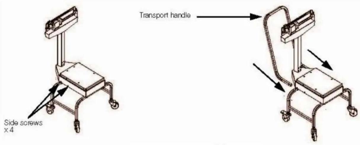
Figure 7. Transport Handle Installation
-
Insert the transport handle into the two sides of the scale support frame as shown in right side of Figure 7.
-
Insert and tighten the four screws using a phillips screwdriver as shown in Figure 8.
natural_image
Close-up of a white office chair with metal frame and curved legs, no visible text or symbolsFigure 8. Insert and Tighten Four Screws for Securing the Transport Handle to the Scale Support Frame The transport handle should fit snuggly against the scale support frame.
Seat and Footrest Installation
Once the transport handle is attached the next step is to install the molded seat to the scale support frame.
- Remove the four screws from the movable scale support frame platform and set aside.
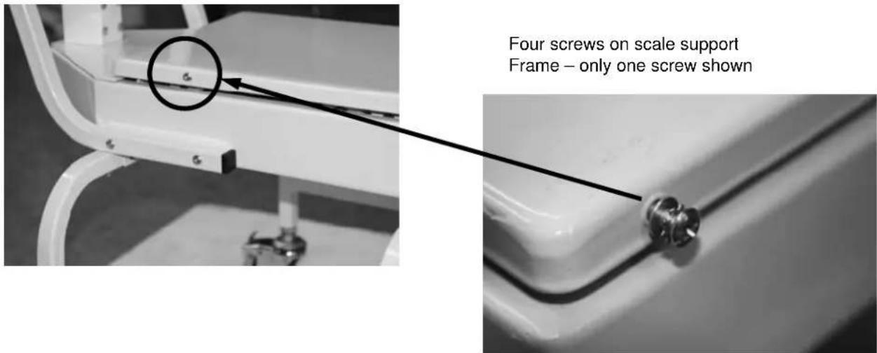
Figure 9. Removable Screws on The Movable Scale Support Frame
- Set the chair onto the scale support frame platform but do not fasten the screws as the footrest assembly will also have to be put into place prior to tightening all screws.
- Remove screws from the chair frame (shown in Figure 10) and set aside.
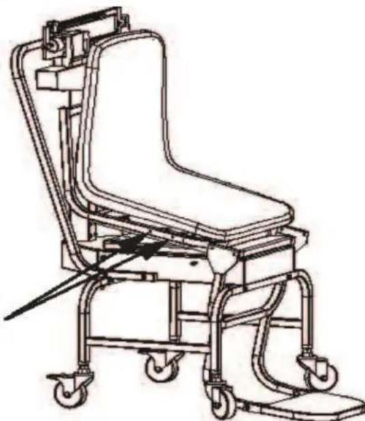
- Tilt the chair upwards as shown in Figure 10. This will allow the installer to get the footrest assembly in place prior to securing the chair to the platform
Remove four screws from chair frame (two on each side) and tilt the chair upwards before installing footrest assembly.
natural_image
Line drawing of a medical mobility device with wheels and adjustable arm (no text or symbols)Figure 10. Tilt the Chair Upward Before Installing the Footrest Assembly
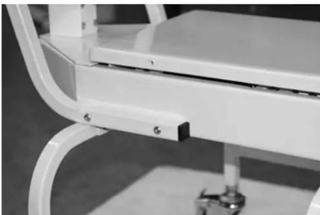
- Slide the footrest assembly onto the chair scale base as shown in Figure 10.
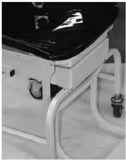
Note that the footrest assembly for the footrest is hanging on the metal chair channel and lined up with the screw holes on the channel of the chair scale frame as shown in Figure 11.
natural_image
Close-up of a medical examination table with black top and white frame (no visible text or symbols)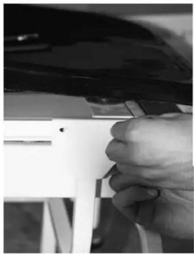
natural_image
Close-up of a hand adjusting a white plastic component with a tool (no visible text or symbols)
natural_image
Close-up of a mechanical component with metal rods and a handle, no visible text or symbolsPush footrest assembly back so that the holes line up.
Figure 11. Slide the Footrest Assembly So That Holes Line Up
Once the footrest is secured and the screws tightened for it, secure the molded seat onto the chair scale frame.
- Secure the four screws (shown below).
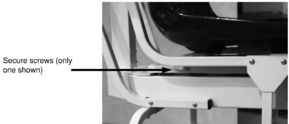
Figure 12. These Screws Hold The Molded Chair to the Scale Base
Arm Rest Installation
The last item to be installed on the mechanical chair scale are the two arm rests.
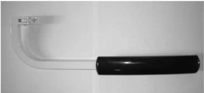
natural_image
Close-up of a black-handled tool handle with a clear glass bracket, isolated on white background (no text or symbols)Figure 13. Detachable Arm Rest for the Mechanical Chair Scale
Use the following steps to attach the two arm rests to the mechanical chair scale molded seat.
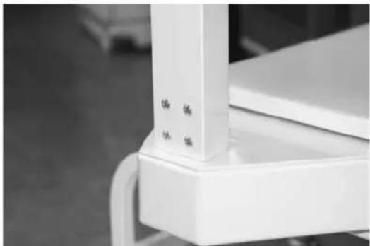
- Locate the bolt hole (x 4) location on the back of the molded chair.
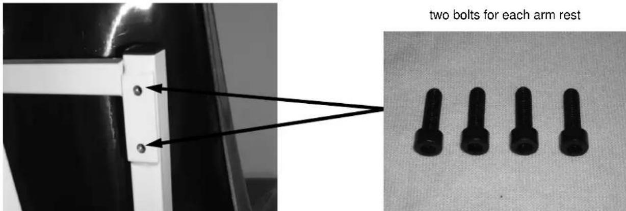
Figure 14. Hole Location and Four Bolts Used for Securing Arm Rest to Chair
- Secure the arm rests to the molded chair using the four bolts (provided and shown in Figure 14), using the 5mm allen wrench that's been provided in this packaging.
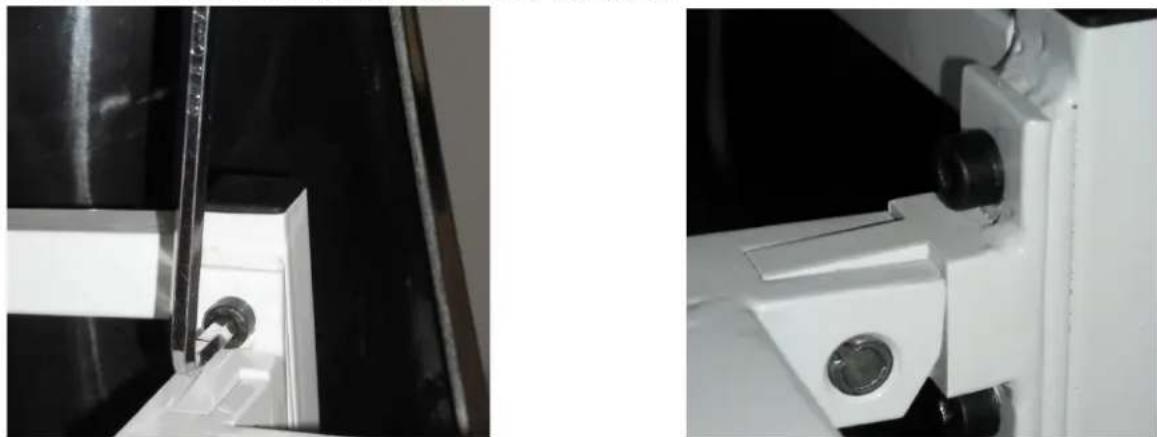
natural_image
Close-up of mechanical components with no visible text or symbolsFigure 15. Secure Arm Rests to the Molded Chair
- The arm rests are now in position and can be moved up and down.
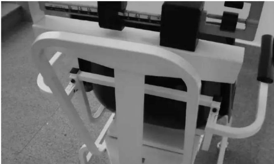
natural_image
Close-up of a white exercise machine with black buttons and control panel (no visible text or symbols)Figure 16. Arm Rests Are Secured to the Molded Chair Seat
Zero Adjustment
To ensure accurate weighments, a zero adjustment should be done to the scale upon arrival and setup. To perform a zero adjustment, perform the following steps.
- Ensure the scale is sitting on a level surface.
- Check the eye loop area of the scale to ensure that the scale pointer is equally balanced between the eye loop area.
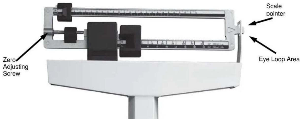
Figure 17. Eye Loop Area and Zero Adjusting Screw Location
-
If the scale is not balancing properly, then the small zero balance weight must be adjusted. Turn the zero adjusting screw (shown in Figure 17) using a flat head screwdriver. By adjusting the screw, the zero balance weight will move accordingly.
-
The scale is now ready to weigh patients.
-
Have the patient sit down on the molded seat. The patient should be completely seated in the chair, not leaning forward, and having feet firmly positioned on the footrest assembly.
Brecknell
USA
Brecknell
1000 Armstrong Drive
Fairmont MN 56031
Toll Free: 800-637-0529
Tel: 507-238-8702
Fax: 507-238-8271
Email:sales@brecknellscales.com
www.brecknellscales.com
UK and Europe
Brecknell
Foundry Lane
Smethwick
West Midlands, B66 2LP.
Tel: +44 (0) 845 246 6717
Fax: +44 (0) 845 246 6718
Email: sales@brecknellscales.co.uk
Web site: www.brecknellscales.co.uk
Brecknell
natural_image
Modern medical mobility chair with black seat and white frame, no visible text or symbolsnatural_image
Close-up of a mechanical control lever with a white arrow pointing to the pivot point (no text or symbols visible)natural_image
Close-up of hands assembling a white electronic device with a screwdriver (no visible text or symbols)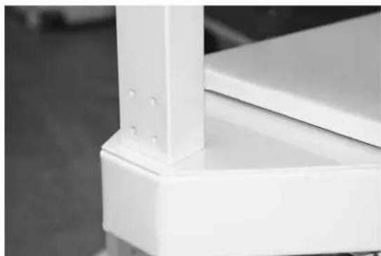
natural_image
Close-up of a white metal bracket with mounting holes and structural details (no text or symbols visible)natural_image
Close-up of a small square electronic component with a black internal structure, placed on a white base (no text or symbols visible)natural_image
Close-up of a white industrial or mechanical component with no visible text or symbolsnatural_image
Close-up of a white office chair with metal legs and a small foot, no visible text or symbolsnatural_image
Line drawing of a mobile medical or rehabilitation chair with wheels and overhead equipment (no text or symbols)natural_image
Close-up of a medical examination table with black top and white frame (no visible text or symbols)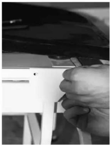
natural_image
Close-up of a hand adjusting a white plastic component with a tool (no visible text or symbols)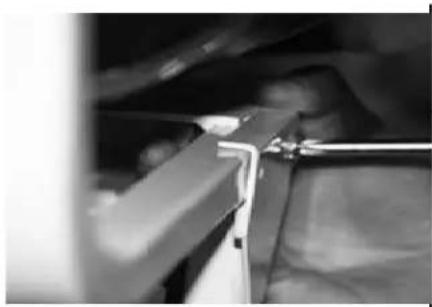
natural_image
Close-up of a mechanical component with a tool inserted, no visible text or symbolsnatural_image
Close-up of a black-handled tool handle with a clear plastic lever (no text or symbols visible)natural_image
Close-up of two mechanical components with metallic parts and mounting holes (no visible text or symbols)natural_image
Close-up of a white mechanical device with curved arms and control panels, no visible text or symbolsWest Midlands, B66 2LP
Tél.: +44 (0) 845 246 6717