SBI-100 - Scale Brecknell - Free user manual and instructions
Find the device manual for free SBI-100 Brecknell in PDF.

| Product Type | Digital Scale |
| Model | SBI-100 |
| Brand | Brecknell |
| Capacity | 100 kg (220 lb) |
| Resolution | 50 g (0.1 lb) |
| Units | kg, lb, g, oz |
| Platform Size | 305 x 305 mm (12 x 12 in) |
| Overall Dimensions | 305 x 330 x 100 mm (12 x 13 x 4 in) |
| Net Weight | 3.5 kg (7.7 lb) |
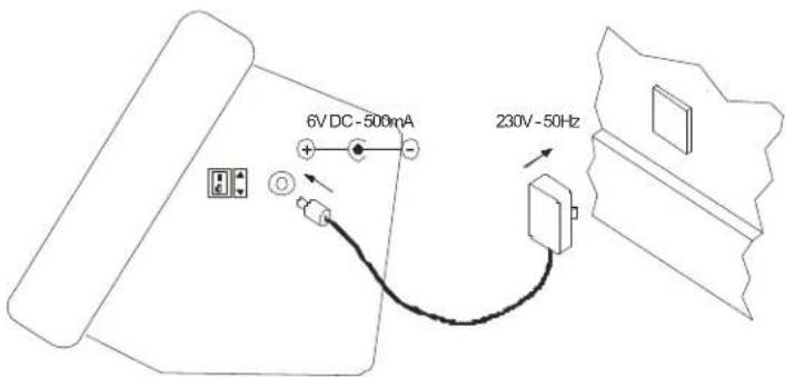
| Power Supply | AC adapter (6V DC, 500 mA) or 6 x AA batteries |
| Display | LCD with backlight, 6-digit |
| Functions | Tare, hold, auto-off, overload indication, low battery indication |
| Operating Temperature | 0°C to 40°C (32°F to 104°F) |
| Material | Stainless steel platform, ABS housing |
| Cleaning | Wipe with a damp cloth; do not immerse |
| Safety Features | Overload protection, auto shut-off |
| Spare Parts | AC adapter, batteries, platform foot |
| Reparability | Calibration and zero adjustment possible via button sequence |
| Certifications | CE, RoHS |
| Warranty | 1 year |
Frequently Asked Questions - SBI-100 Brecknell
User questions about SBI-100 Brecknell
0 question about this device. Answer the ones you know or ask your own.
Ask a new question about this device
Download the instructions for your Scale in PDF format for free! Find your manual SBI-100 - Brecknell and take your electronic device back in hand. On this page are published all the documents necessary for the use of your device. SBI-100 by Brecknell.
USER MANUAL SBI-100 Brecknell
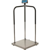
natural_image
Exterior view of a Brecknell medical device with digital display, cable, and mounting bracket (no readable text or symbols)User Instructions
Brecknell is part of Avery Weigh-Tronix. Avery Weigh-Tronix is a trademark of the Illinois Tool Works group of companies whose ultimate parent company is Illinois Tool Works Inc ("Illinois Tool Works"). Copyright © 2013 Illinois Tool Works. All rights reserved.
No part of this publication may be reproduced by making a facsimile copy, by the making of a copy in three dimensions of a two-dimensional work and the making of a copy in two dimensions of a three-dimensional work, stored in any medium by electronic means, or transmitted in any form or by any means, including electronic, mechanical, broadcasting, recording or otherwise without the prior written consent of the copyright owner, under license, or as permitted by law.
This publication was correct at the time of going to print, however Avery Weigh-Tronix reserves the right to alter without notice the specification, design, price or conditions of supply of any product or service at any time.
Table of Contents
Chapter 1 General Information and Warnings ....3
About this Manual 3
Special Messages ....3
Warnings 4
Electrical Installation 4
Routine Maintenance 4
Safe Use 5
Cleaning the Indicator / Weigh Head 5
Training 5
EMC Compliance 5
Declaration of Compliance 6
Chapter 2 Introduction ......7
Product Identification 7
Technical Specifications 7
Setup the Indicator for Use 9
Connect the Indicator to the Platform 9
Power Supply 10
Display and Keypad 10
Function Keys 11
Annunciators 11
Chapter 3 Scale Operation ....13
Keypress Symbols 13
Turning on and Zeroing the Scale 13
Turning off the Scale 13
Select Unit of Measure 13
Using the Tare 14
Remove the Tare 14
Hold Function with Automatic Zero on Next Weigh 14
Hold Function with Manual Release 15
Removing Hold 16
Print Function 16
Chapter 4 User Configuration Settings ...... 17
Setup Controls 17
Entering Setup 17
Selecting a Parameter 17
Changing Parameter Data 17
Saving Data 18
Exiting Setup 18
User Configuration Settings 19
RS-232 Data Commands for SBI Protocol 20
Output Status Bit Meaning 21
Other RS-232 Output Strings 21
RS-232 Serial Interface Wiring 22
Chapter 5 Scale Calibration ......23
Setup Controls 23
User Configuration Settings 23
Calibrate Scale 24
Chapter 6 Service Configuration ...... 26
Setup Controls 27
Parameters and Settings 27
1 General Information and Warnings
1.1 About this Manual
This manual is divided into chapters by the chapter number and the large text at the top of a page. Subsections are labeled as shown by the 1 and 1.1 headings shown above. The names of the chapter and the next subsection level appear at the top of alternating pages of the manual to remind you of where you are in the manual. The manual name and page numbers appear at the bottom of the pages.
1.1.1 Special Messages
Examples of special messages you will see in this manual are defined below. The signal words have specific meanings to alert you to additional information or the relative level of hazard.

CAUTION!
This is a Caution symbol.
Cautions give information about procedures that, if not observed, could result in damage to equipment or corruption to and loss of data.
ELECTRICAL WARNING!
THIS IS AN ELECTRICAL WARNING SYMBOL.
ELECTRICAL WARNINGS MEAN THAT FAILURE TO FOLLOW
SPECIFIC PRACTICES OR PROCEDURES MAY RESULT IN
ELECTROCUTION, ARC BURNS, EXPLOSIONS OR OTHER HAZARDS
THAT MAY CAUSE INJURY OR DEATH.

NOTE: This is a Note symbol. Notes give additional and important information, hints and tips that help you to use your product.
1.2 Warnings
Avoid lengthy exposure to extreme heat or cold. Your scale works best when operated at normal room temperature. Always allow the scale to acclimate to a normal room temperature before use.

CAUTION! THE EQUIPMENT CONTAINS NO USER SERVICEABLE COMPONENTS.
Installation and maintenance of the equipment must only be carried out by trained and authorised personnel.
1.2.1 Electrical Installation
The mains lead must be connected to a supply outlet with a protective earth contact. The electrical supply at the socket outlet must provide over current protection of an appropriate rating.
For your protection all mains (110V or 230V) equipment used out of doors or in wet or damp conditions should be supplied from a correctly fused source and protected by an approved ground fault protection device (RCD, GFCI etc.)
IF IN DOUBT SEEK ADVICE FROM A QUALIFIED ELECTRICIAN.
1.2.2 Routine Maintenance

IMPORTANT: This equipment must be routinely checked for proper operation and calibration. Application and usage will determine the frequency of calibration required for safe operation.
ELECTRICAL WARNING! TO AVOID THE POSSIBILITY OF ELECTRIC SHOCK OR DAMAGE TO THE MACHINE, ALWAYS SWITCH OFF THE MACHINE AND ISOLATE FROM THE POWER SUPPLY BEFORE CARRYING OUT ANY ROUTINE MAINTENANCE.
TO AVOID THE RISK OF THE MACHINE FALLING, WHERE APPLICABLE, ENSURE THAT IT IS PLACED SECURELY ON A FLAT AND LEVEL SURFACE.
Do not use sharp objects such as screwdrivers or long fingernails to operate the keys.
1.3.1 Cleaning the Indicator / Weigh Head
Harsh abrasives, solvents, scouring cleaners and alkaline cleaning solutions, such as washing soda, should not be used especially on the display windows. Under no circumstances should you attempt to wipe the inside of the machine.
The outside of standard products may be wiped down with a clean cloth, moistened with water containing a small amount of washing up liquid.
The outside of products waterproofed to IP65, IP66 and IP67 may be washed down with water containing a small amount of proprietary detergent.
1.3.2 Training
Do not attempt to carry out any procedure on a machine unless you have received the appropriate training or read the Instruction Manual.
1.3.3 EMC Compliance
Do not attempt to carry out any procedure on a machine unless you have received the appropriate training or read the Instruction Manual.

WARNING!
This is a class A product. In a domestic environment this product may cause radio interference in which case the user may be required to take adequate measures.

Brecknell, a trading name of Avery Weigh-Tronix Ltd.,
Foundry Lane, Smethwick, West Midlands B66 2LP, England
| CE | Declaration of ConformityVerklaring van OvereenstemmingDéclaration de Conformité | KonformitätserklärungDichiarazione di conformitàDeclaración de Conformidad |
| Manufacturer Type | Avery Weigh-Tronix LimitedBrecknell S100, SBI100 |
| corresponds to the requirements of the following EC directives: | |
| EMC DirectiveLow Voltage Directive | 2004/108/EC2006/95/EC |
| The applicable harmonised standards are: | |
| EN 61000-6-1: 2007EN60950-1:2006 | EN 61000-6-3: 2007 |
| Avery Weigh-Tronix LimitedReg. Office: Foundry Lane, Smethwick, West Midlands B66 2LP, England Registered in England No.: 595129 | |
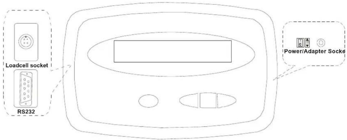
2.1 Product Identification
| Part Number Capacity Region Power Supply (s) | |||
| 816965001620 75 kg | x 0.01kg / 150lb x 0.02lb | North America US | Version, UL |
| 816965001637 150 kg | x 0.02kg / 300lb x 0.05lb | North America US | Version, UL |
| 816965001644 300 kg | x 0.05kg / 600lb x 0.1lb. | North America US | Version, UL |
| 816965002160 75 kg | x 0.01kg / 150lb x 0.02lb. | UK/EU 3 pin | JK & 3 pin EU,CE approved |
| 816965002177 150 kg | x 0.02kg / 300lb x 0.05lb. | UK/EU 3 pin | JK & 3 pin EU,CE approved |
| 816965002184 300 kg | x 0.05kg / 600lb x 0.1lb. | UK/EU 3 pin | JK & 3 pin EU,CE approved |
| 816965002719 75 kg | x 0.01kg / 150lb x 0.02lb. | AUS/SA 3-pin | Australia C-Tick approved, 3 pin South Africa |
| 816965002726 150 kg | x 0.02kg / 300lb x 0.05lb. | AUS/SA 3-pin | Australia C-Tick approved, 3 pin South Africa |
| 816965002733 300 kg | x 0.05kg / 600lb x 0.1lb. | AUS/SA 3-pin | Australia C-Tick approved, 3 pin South Africa |
2.2 Technical Specifications
| Scale Indicator | |
| Input signal range: 0mV ~ +30mV | |
| Sensitivity: >0.2μV/grad | |
| Internal Resolution: Approximate | y 520,000 counts |
| Display Resolution: | Can be selected between 500-100,000 |
| System Linearity: | Within 0.01% of FS |
| Loadcell excitation Voltage: +5 V | DC (MAX current: 85mA) |
| Loadcell | |
| Sensitivity: 0.3mV/V --- 3mV/V (m | must be fit to >0.2μV/display grad.) |
| Input Resistor: | ≥60 Ω |
| Output Resistor: | <10 KΩ |
| Temperature | |
| Operation: | 5°C - 35°C |
| Storage: | 10°C - 70°C |
| Humidity: ≤95%RH (no condensation) | |
| Power | |
| Battery: 6V4AH lead acid battery; | 30 hrs continuous use |
| When the voltage of battery is below 5.7V, the "Low Bat" annunciator will be lighted, plug in AC adapter to charge the battery. When "Lo.bAt" and actual weight is displayed alternately, this indicates the voltage of battery is below 5.5V and the scale will be turned off in two minutes automatically. | |
| AC Adapter: |  |
| 10.5-12VDC 600mA, with central positive, 5.7 VDC -9 VDC | |
2.3 Setup the Indicator for Use
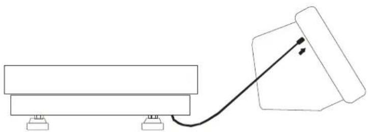
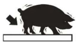
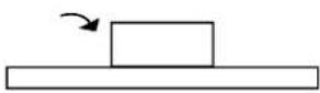
2.3.1 Connect the Indicator to the Platform
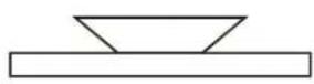
natural_image
Simple line drawing of a mechanical setup with a block and connecting rod (no text or symbols)Wire the cable attached to the base as shown (if necessary)
- Red Excitation+
- Black Excitation-
- Green Signal-
- White Signal+
2.3.2 Power Supply
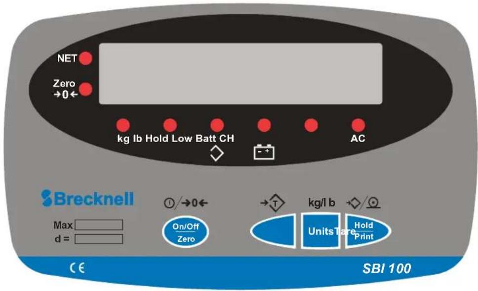
2.4 Display and Keypad
2.4.1 Function Keys
| Key Function | |
 | Tare a gross weight |
  | Turn the indicator ON or OFFZero an applied weight |
  | Select between units: kg or lb |
  | Hold a weightPrint |
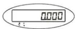
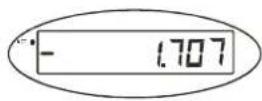
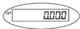
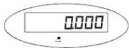
2.4.2 Annunciators
| Annunciator Description | |
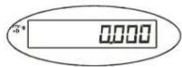
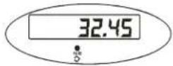
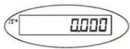
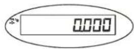
 | Weight is zero |
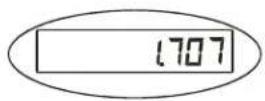
 [300H] [300H] | Unit of measure (Flashing LED means that the weight reading is not stable.)Tare is activated |
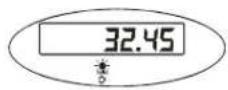
 | Battery is charging |
| [8HA0] | AC adapter is plugged in |
 | Hold is activated |
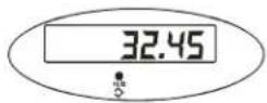
 | Battery is low |
3 Scale Operation
3.1 Keypress Symbols

short keypress multiple keypress long keypress


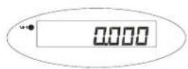
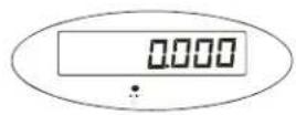
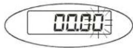
3.2 Turning on and Zeroing the Scale


3.3 Turning off the Scale


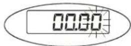
3.4 Select Unit of Measure


kg - lb
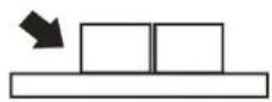
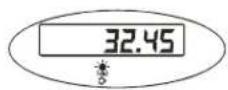
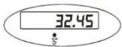
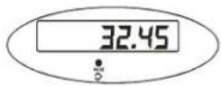
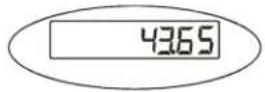
3.5 Using the Tare
1.
2.


3.
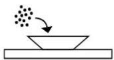
4.
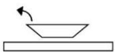
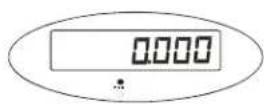
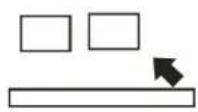
3.6 Remove the Tare


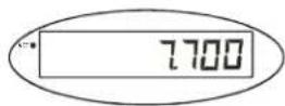
3.7 Hold Function with Automatic Zero on Next Weigh
1.


3.8 Hold Function with Manual Release


3.9 Removing Hold

3.10 Print Function
For communications to a printer or PC, the indicator has to be setup in the following parameters P2, P4, P5 and P6. Refer to Chapter 4.
1.
2.

3.
4 User Configuration Settings
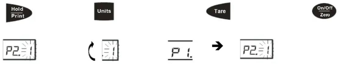
4.1 Setup Controls
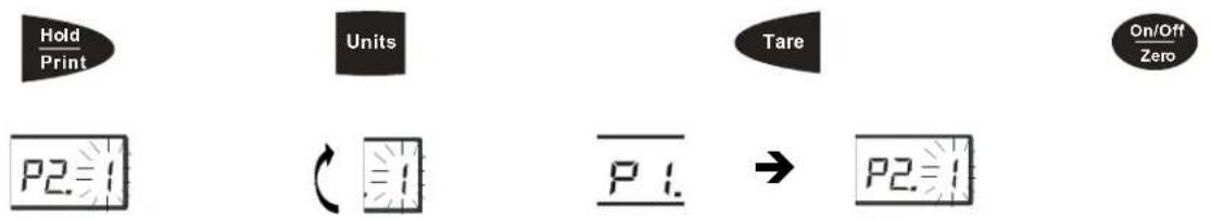
flowchart
graph LR
    A["Hold Print"] --> B["Units"]
    B --> C["Tare"]
    C --> D["On/Off Zero"]
    E["P2=1"] --> F["Units"]
    F --> G["P1"]
    G --> H["→"]
    H --> I["P2=1"]
Moves flashing digit Change flashed digits Saves data and move down to next
parameter setting
Exits setup mode
4.2 Entering Setup

4.2.1 Selecting a Parameter

4.2.2 Changing Parameter Data

4.2.3 Saving Data


4.2.4 Exiting Setup


4.3 User Configuration Settings
| Parameter Description | Settings (default in bold) | |
| P1.xy Auto shutoff timer in minutesSet up time for the auto off function.(00 = 0ff, 01-15 = time in minutes) | P1.00P1.01 - P1.15P1.5 = 15 minutes | |
| P2.x Hold and print key functionalitySetup button function0 = Press button once to activate hold1= Press button once to print2= Press button to print/Press and hold button to activate hold. | P2.0= HoldP2.1= PrintP2.2= Print & Hold | |
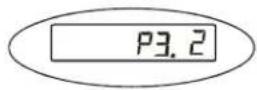
| P3.xy Hold Function Settings0= No hold function active1= Averaging hold with manual push button releaseThe weight reading will be held on the display until a higher weight is applied, this will automatically release the held weight and re-hold it at the new higher weight reading.2= Averaging hold with automatic release and re-holdSame as above but the weight reading will be held on the display until the platform is emptied and the next weight reading over 10 divisions is applied.3-50= Selectable hold window from +/- 3 to 50 divisionsWill hold display reading once stable within a selectable weight range, to release the hold button must be repressed. | P3.0P3.1P3.2P3.3 to 50 | |
| P4.x RS232 - Serial InterfaceSettings for serial interface0= No RS232 output1= Print displayed data once stable when print key is pressed2= Print gross, tare and net weight once stable when print key is pressed3= Continuously output gross weight4= Continuously output gross, tare and net weight5= Print displayed data once stable one time only.6= Print gross, tare and net weight once stable, one time only.7= Bidirectional - RS232, SBI protocol | P4.0P4.1'P4.2P4.3P4.4P4.5P4.6P4.7 | |
| P5.x RS232 Baud rate P5.0= 1200 | P5.1= 2400P5.2= 4800P5.3= 9600P5.4= 19200 | |
| P6.x RS232 Data format0 = 8 digits, no odd or even, 1 start bit, nan1 stop bit1 = 7 digits, 1 even, 1 start bit, 1 stop bit2 = 7 digits, 1 odd, 1 start bit, 1 stop bit3 = 8 digits, no parity, 1 start bit, 1 stop bit | P6.0P6.1P6.2P6.3 | |
| P7-P19.x SERVICE CONFIGURATIONS ONLYAny adjustment to these settings could seriously affect the indicators performance. Seek advice from a service engineer before changing. | ||
The RS232 can be set so a bidirectional connection can be established between the indicator and the host. To establish this connection, set parameter P4 to 7, and configure setting P5 (baud) and P6 (parity) to host device. Commands can then be sent from the host to the indicator using the following commands (ensure the letters entered are in CAPS) (
| Key Symbols | |
| Line feed | |
| Carriage Return | |
| End of text character | |
| Space | |
| H1H2H3 3 status bytes | |
| Polarity character including minus sign for negative weigh and a space character for positive. | |
| W1-W7 Weight data | |
| Decimal point | |
| U1U2: Unit measure, kg, lb or oz | |
| Command Action Response | ||
| WTakes a readingover capacityunder capacityzero point errorreading (kg or lb) | ||
| S | prints status bytes | H1H2H3 |
| Z | zeros the scale | H1H2H3 |
| T | sets up a tare | H1H2H3 |
| U | changes the units | U1U2H1H2H3 |
| L | activates the hold function | H1H2H3 |
| X | switches off the scale | Indicator switches off |
| ? | unrecognised command | ? |
4.4.1 Output Status Bit Meaning
| Bit Byte | 1 Byte 2 Byte 3 | ||
| 0 0=Stable | 0=Not Under Capacity | 00=Not defined | |
| 1=Unstable 1=Under Capacity | 01=Normal working mode | ||
| 1 0=Not | at zero point 0=Not over | capacity 10=Hold working mode | |
| 1=At zero point | 1=Over capacity | 11=Not defined | |
| 2 Always | 0 Always | 0=Gross | Weight1=Net Weight |
| 3 | 0=eprom OK1=eprom error | Always 0 | Always 0 |
| 4 Always | 1 Always | 1 Always | 1 |
| 5 Always | 1 Always | 1 Always | 1 |
| 6 Always | 0 Always | 1 Always | 0 |
| 7 | Parity | Parity | Parity |
4.4.2 Other RS-232 Output Strings
P4-1 = Output Displayed data @ print key
Format:
Example:
xxxxx0.18lb
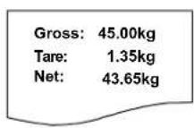
P4-2 = Output Gross, Tare, Net @ print key
Format:
Example:
Gross: xxxxx0.18lb
Tare: xxxxxx0.18lb
Net: xxxxxxxx0.18lb
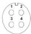
4.4.3 RS-232 Serial Interface Wiring
| DE-9 Female Scale DE-9 Male Host | |||||
| Pin Name | Direction | Pin Name | Direction | ||
| 2. TXD | Out 2. RXD In | ||||
| 3. RXD | In 3. TXD | Out | |||
| 5. | SG | - | 5. | Ground | - |
| Pins 1, 4, 6, 7, 8, 9 not used | |||||
5 Scale Calibration
The scale is configured from the factory to match the specified settings for each unit, as defined by the product specifications and sales brochure. Modification of the settings can be accomplished by altering user configuration settings P7-P10.

CAUTION!
Calibration and/or configuration of calibration settings of your scale should be accomplished by a trained service technician using certified weights to ensure proper operation and accuracy. Calibration is not covered under warranty.
5.1 Setup Controls
Moves flashing digit Change flashed digits Saves data and move down to next
parameter setting
Exits setup mode
5.2 User Configuration Settings
| Config Menu | Avail. Settings | Definition Detailed Setting | |||
| P7 00-31 | Displayed Resolution (00) = 500 | (08) = 2400(09) = 2500(10) = 3000(11) = 3500(12) = 4000(13) = 5000(14) = 6000 | (15) = 7000(16) = 7500(17) = 8000(18) = 10,000(19) = 12,000(20) = 15,000(21-31) = N/A | ||
| (01)= 600(02)= 750(03)= 800(04) =1000(05)=1200(06) =1500(07) = 2000 | |||||
| P8 0,1,2 | Division Increment 0 = 1; 1 = 2; 2 = 5 | ||||
| P9 | 0-5 | Decimal Position | 0 = 123456; 1 = 12345.6; 2 = 1234.56;3 = 123.456; 4 = 12.3456; 5 = 1.23456 | ||
| P10 | 0,1 | Calibration weight | 0 = kg; 1 = lb | ||
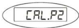
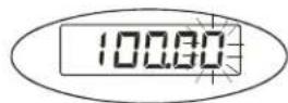
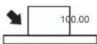
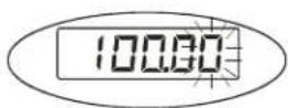
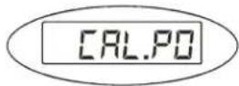
5.3 Calibrate Scale
You may choose to configure your scale for a higher resolution. The factory does not recommend increasing the resolution above 7,500 divisions for a stable weight reading. Certain environments may cause the scale to be unstable at factory settings, reduce the # of division settings to increase your stability.
Calibration can be done with 25% to 100% of requested load and can be calibrated with 1 or 2 calibration points
1.


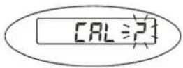
2.


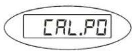
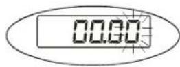
3.


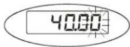
- Enter in calibration weight from 25% to 100% of full capacity
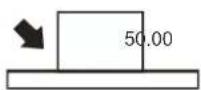


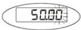
- Single point calibration, enter the same weight in again and move to step 7. For 2 point calibration enter in the second calibration weight between 25% 100% full capacity.


6.


7.


8.

9.


6 Service Configuration
The scale is configured from the factory to match the specified settings for each unit, as defined by the product specifications and sales brochure. Modification of the setting can be accomplished by altering user configuration settings P11-P19.

CAUTION!
Calibration and/or configuration of calibration settings of your scale should be accomplished by a trained service technician using certified weights to ensure proper operation and accuracy. Calibration is not covered under warranty.
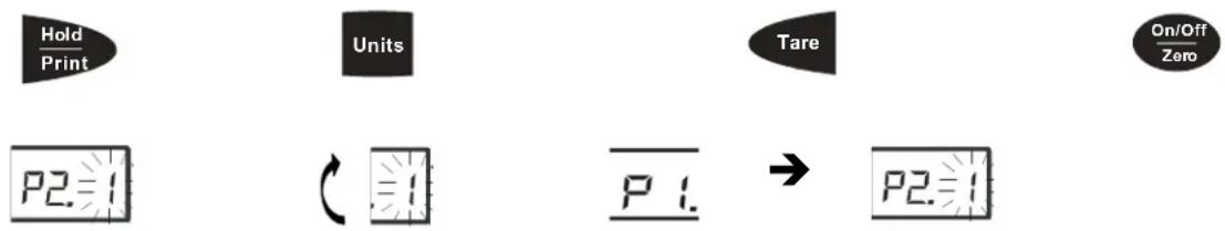
6.1 Setup Controls
flowchart
graph LR
    A["Hold Print"] --> B["Units"]
    B --> C["Tare"]
    C --> D["On/Off Zero"]
    E["P2=1"] --> F["Units"]
    F --> G["P1"]
    G --> H["→"]
    H --> I["P2=1"]
Moves flashing digit Change flashed digits Saves data and move down to next
parameter setting
Exits setup mode
6.2 Parameters and Settings
| Config Menu | Avail. Settings | Default Definition Detailed Setting | |
| P11 0,1,2 | 2 Units key configuration 0 = | kg only | 1= lb only2 = units key active kg and lb |
| P12 0 - 7 | 7 Power on zero range | (full scale) | 0 = +/- 1%1 = +/- 2%2 = +/- 5%3 = +/- 10%4 = +/- 20%5 = +/- 50%6 = +/- 100%7 = no limitation |
| P13 00 - 15 | 3 Zero button range | (full scale) | (00) = +/- 1%(01)= +/- 2%(02)= +/- 3%(03)= +/- 4%(04)= +/- 5%(05)= +/- 10% (06) = +/- 20%(07) = +/-no limit (08)= + 1%(09) = + 2%(10)= + 3%(11) = + 4% (12) = + 5%(13) = + 10%(14) = + 20%(25) = + no limit |
| P14 | 0,1,2 0 Signal within power on zero point range | 0 = current weight1 = calibration zero2 = power off zero point | |
| Config Menu | Avail. Settings | Default | Definition | Detailed Setting |
| P15 0,1,2 | 1 Signal not within power on | zero point | 0 = current weight1 = calibration zero2 = power off zero point3 = continuously display “0----” | |
| P16 0 - 8 | 6 Zero tracking 0 | = 0d AZT off | 1 = +/- 0.25d2 = +/- 0.5d3 = +/- 1d4= +/- 1.5d5= +/- 2d6 = +/- 3d7= +/- 4d8 = +/- 5d | |
| P17 0 - 3 | 2 Data filter 0 = very weak | 1 = weak2 = standard3 = strong | ||
| P18 0 - 9 | 1 Weight stability | 0 = +/- 0.5d | 1= +/- 1d2= +/- 1.5d3= +/- 2d4= +/- 3d5= +/- 4d6 = +/- 5d7= +/- 6d8 = +/- 7d9 = +/-8d | |
| P19 0 - 9 | 1 Overload range | full scale 0 = 0% | 1 = +9d2 = 101%3 = 102%4 = 405%5 = 110%6 = 120%7 = 150%8 = 200%9 = no limitation | |
7 Error Codes
| Error Message | Definition Required Solution/Troubleshooting | |
| 0____: | Weight above range for calibrated zero point. | Remove load before zeroing Or Recalibrate the scale. |
| 0____: | Weight below range for calibrated zero point. | Remove load before zeroing Or Recalibrate the scale. |
| ____: | Indicates an under range condition Remove all loads and zero the scale. | |
| ____: | Capacity exceeded | Remove the load and try again. If the load is great than 6 kg a scale with a larger capacity is required. |
| CAL-Er: | Calibration error Restart calibration | |
| Lo.bAt: | Low Battery Recharge the battery. Upon initial use, it is recommended to charge battery for 8 hours prior to use. | |
| EEP.E0 | EEPROM can't be accessed | Replace S100 Indicator |
| EEP.E1 | Configuration settings have changed and not been stored | Calibrate the scale to store settings |
| EEP.E2 | P7-P9 settings exceed scale's normal range | Reconfigure P7-P9 setting |
Brecknell USA
1000 Armstrong Dr.
Fairmont MN 56031
Tel:507-238-8702
Fax:507-238-8271
Email: sales@brecknellscales.com
http://www.brecknellscales.com
Brecknell UK
Foundry Lane,
Smethwick, West Midlands,
England B66 2LP
Tel:+44 (0) 8452 46 6717
Fax:+44 (0) 8452 46 6718
Email:
sales@brecknellscales.co.uk
http://www.brecknellscales.com