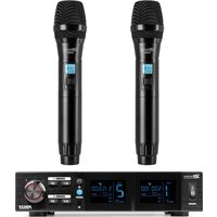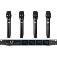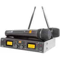
PD782 - Microphone Power Dynamics - Free user manual and instructions
Find the device manual for free PD782 Power Dynamics in PDF.



Frequently Asked Questions - PD782 Power Dynamics
User questions about PD782 Power Dynamics
0 question about this device. Answer the ones you know or ask your own.
Ask a new question about this device
Download the instructions for your Microphone in PDF format for free! Find your manual PD782 - Power Dynamics and take your electronic device back in hand. On this page are published all the documents necessary for the use of your device. PD782 by Power Dynamics.
USER MANUAL PD782 Power Dynamics
natural_image
Two black wireless audio devices with two external antennas and external screens, no visible text or symbols.179.193 - PD781 Wireless Mic UHF 1x8Ch
179.196 - PD782 Wireless Mic UHF 2x8Ch
Instruction Manual
Gebruiksaanwijzing
Gebrauchsanleitung
Thanks for purchasing this product, please read this instruction carefully so that can understand how to operate the product of style you bought correctly. Please store this instruction in a safe place after reading as a reference in the future. This series of professional wireless microphone system used a super steady PLL-synthesized control technique and match with the high efficient, low consumption discharging technique.
Warning
- Always read the manual before using the product.
- Keep the manual so every new user can read it before using the product.
- Always keep the packaging. When a malfunction occurs, please send it in the original packaging.
- Only for indoor use. Do not use in moistures places.
- Don't expose to direct sunlight or heat sources. Don't block ventilation openings.
- Don't let small objects or fluids enter the housing. Don't put candles on it. This may cause malfunction.
- Clean this unit with a dry cloth. Don't use cleaning fluids or solvent.
- Unit contains no serviceable parts. Only the replacement parts named in this manual can be changed by the user or servicing personnel.
- Never open the unit, service may only be done by qualified personnel.
- Never remove or place the mains plug in a socket with wet hands.
- Disconnect the unit from mains power before servicing.
- Condensation water can form while reusing, please let the unit reach the environmental temperature before using it.
- Keep out of children's reach.
- When the unit is damaged in a way that internal parts are visible. NEVER connect the unit to a mains socket and NEVER switch the unit on. In this case, contact your supplier. - When a lightning storm occurs, always disconnect this unit from the mains socket. Do the same when the unit won't or hasn't be used for a long period of time.
- Using this unit might cause disturbance in insufficiently shielded equipment. This disturbance might cause damage or accidents. Please check if there is any sensitive equipment in close proximity of the unit before installing it.

Electric products must not be put into household waste. Please bring them to a recycling centre. Ask your local authorities or your dealer about the way to proceed. The specifications are typical. The actual values can slightly change from one unit to the other. Specifications can be changed without prior notice.
Do not attempt to make any repairs yourself. This would invalid your warranty. Do not make any changes to the unit. This would also invalid your warranty. The warranty is not applicable in case of accidents or damages caused by inappropriate use or disrespect of the warnings contained in this manual. Power Dynamics cannot be held responsible for personal injuries caused by a disrespect of the safety recommendations and warnings. This is also applicable to all damages in whatever form.

€ This product is for license free use in all EU member states.
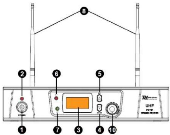
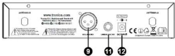
FRONT- AND BACKSIDE
179.193 PD781 Wireless Microphone UHF 1x8Ch 1 Microphone
179.196 PD782 Wireless Microphone UHF 2x8Ch 2 Microphone
text_image
8 2 6 5 UHF POWER 1 7 3 4 10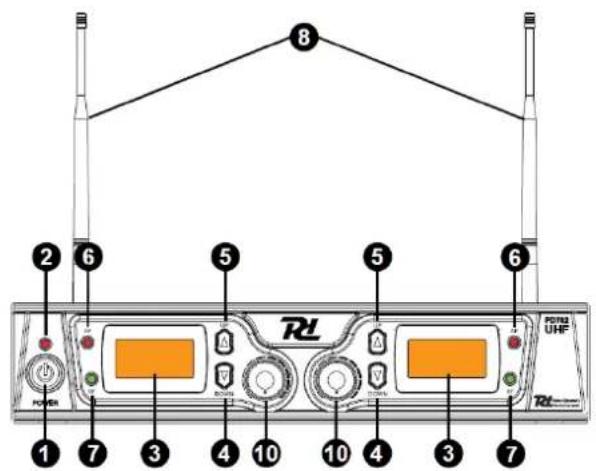
text_image
8 2 6 5 5 6 1 7 3 4 10 10 4 3 7 RSU UHF RSI- Power switch to switch ON/OFF the system
- Power indicator ON/OFF
- LCD Information Display: Show the receiver frequency channel ect.
- Down button: Sets channel data.
- Up button: Sets channel data.
- "AF" Audio level indicator: Indicate the wireless system audio signal level.
- "RF" signal Indicator: Indicate when receive RF signal from transmitter.
- Antenna.
text_image
ANTONIA-5 www.tronios.com Tronios 2.0, Bedicronach Trench 4.0 NBRINCA 183.0, The Antenna Antenna A 9 11 12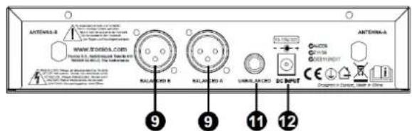
text_image
ANTENAL-B www.tronion.com RALAMPO B RALAMPO A UNIC LUXO DC INPUT ANTENNA-A 9 9 11 12-
XLR- connector balanced: Connect the audio cable from this jack to the input port of amplifier, mixer.
-
Volume knob
- 1/4" Jack connector: Connect the audio cable from this jack to the input port of amplifier, mixer.
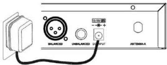
- Power inlet, 12-15Vdc
HANDHELD TRANSMITTER
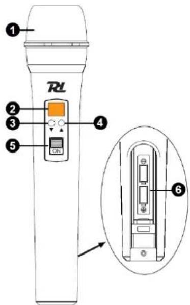
text_image
RL 1 2 3 4 5 ON 6- Grille: Protects the cartridge and help reducing the breath sounds and wind noise.
- LCD Information Display: Show the transmitter frequency channel ect.
- Down button: Sets channel data.
- Up button: Sets channel data.
- Power ON/OFF and Audio Mute Switch.
- Battery Cover: Open it to install the battery. remove batteries in case of long time no use (prevent leakage).
BODYPACK TRANSMITTER (OPTIONAL)
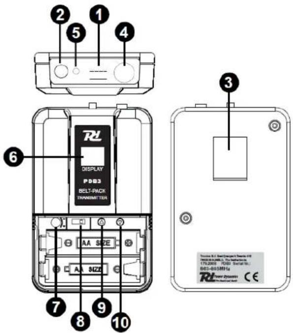
text_image
2 1 4 5 6 DISPLAY P003 BELT-PACK TRANSMITTER AA SIZE AA SIZE 7 8 9 10 3 Tension: 3.1 Real-Compact Transmission 45 179.2003 RDB Serial No. 863-865MHz Power Drive CE- Power ON/OFF and Audio mute switch.
- Antenna: Transmit the RF signal of transmitter.
- Belt Clip
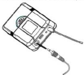
- Audio Input Jack: it is suitable for lavalier tie-clip or headset system.
- Low Battery Indicator: Red light glows when the power is low and change the battery.
- LCD Information Display: Show the transmitter frequency channel ect.
- Gain Adjusting Volume: Adjust the transmitter audio input gain.
- State Setting Switch: Set the using state of lavalier tie-clip or headset system.
- Up Function Button: Sets channel data.
- Down Function Button: Sets channel data.
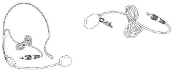
natural_image
Line drawings of two medical or electronic devices: a head-mounted device with earbuds and cable connectors, and a coiled medical device with connectors (no text or symbols)LAVALIER TIE-CLIP MICROPHONE
Connect the connector of supplied lavalier microphone to the connecting jack of transmitter (Shown as below). Set the transmitter work state in wireless lavalier system (8).
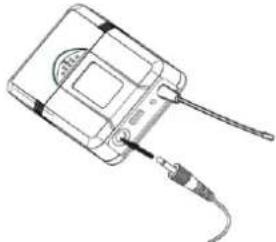
natural_image
Line drawing of a handheld electronic device with cable and connector (no text or symbols)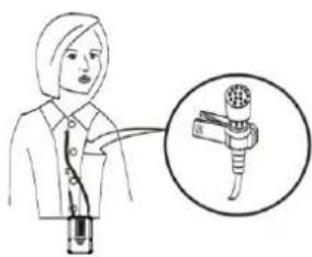
natural_image
Illustration of a person holding a tool with a magnified inset showing the tip of the tool (no text or symbols present)HEADSET MICROPHONE
Connect the connector of supplied headset microphone to the connecting jack of transmitter (Shown as below). Set the transmitter work state in wireless headset system (8).
natural_image
Line drawing of a handheld electronic device with cable and connector (no text or symbols)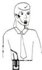
SYSTEM CONNECTIONS
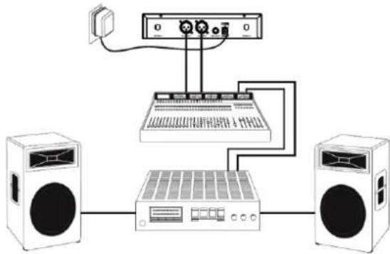
- Receiver power connection: Connect the AC adapter into the DC power connector on the back of the receiver. Plug the AC adapter into a AC230V 50Hz outlet.
text_image
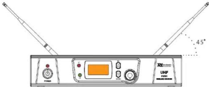
BALANCED UNBALANCED 15-16V RT OUTPUT ANTENIA-A- Antenna: Keep the position of antenna at a 45° angle from vertical. Shown as below.
text_image
45° UHF P201- Audio connection: Connect the audio cable from the audio output on the receiver to the input on your amplifier equipment.
natural_image
Diagram of a network device with two speakers, an audio workstation, and a server connected to a power interface (no text or labels)OPERATION
Turn off the system first, turn down the receivers volume to the minimum and then turn on the receiver, CPU initializes, the LCD screen begins to display and the system reverts to the last shutdown's state!
Tune to the desired frequency of the receiver and observe the RF- and AF signal level. If the signal level is displayed it means the receiver has interference from other signals or noise. The system has a mute circuit to avoid interference noise. If interfere with each other occurs it is recommended to use other frequencies. If the system is turned on look at the transmitter and receiver's frequency.
Then the receiver display shows RF signal level value, the antenna status will display antenna A or B. Adjust the volume to the desired level.
Volume adjustment
Adjust the receiver's volume to the 12 o'clock position, then adjust the volume of the amplifier or mixer to a desired level. If the receiver volume has been adjusted too loud the amplifier will produce a saturated distortion which will blow the amplifier or/and the loudspeaker(s)!
Best acoustics:
- You should always see the receiver antenna from your transmitter location.
- The distance between transmitter and receiver should be as short as possible.
- If the receiver has two antennas, they should be adjusted 45° with a vertical line.
- Keep the antennas away from metal surfaces and shelter.
- Let the antennas not contact or cross each other.
- Before using the system during the presence of public do a test to find out where the "dead spots" are. Avoid these spots when operational.
TROUBLESHOOTING
| PROBLEM | INDICATOR | SOLUTION |
| No sound | Red transmitter indicator is not flash | Slide transmitter POWER ON/OFF switch to ON position. Make sure battery is inserted properly, observing battery (+ / -). If battery is inserted properly, replace with fresh battery. |
| No sound | Red transmitter indicator is flash. | Slide transmitter MUTE/ON switch to ON position. |
| No sound | Red receiver indicator POWER light off. | Make sure AC adapter is securely plugged into electrical outlet and into DC input connector.Make sure AC electrical outlet works and supplies proper voltage. |
| No sound | Receiver signal indicators A/B lights glowing. | Turn up receiver volume control. Confirm that the output connections from the receiver to the external equipment are secure. |
| No sound | Receiver signal indicators A/B lights off. Transmitter and receiver POWER light glowing. | Confirm transmitters and receivers frequencies match. Move transmitter closer to receiver. |
| Sound level differs from level of a cabled instrument. | Receiver signal indicators A/B lights glowing. | Adjust transmitter gain level to compessary.Adjust receiver volume as necessary. |
| Distortion level increases gradually | Receiver signal indicators A/B lights and transmitter LOW BATTERY light glowing | Replace transmitter battery |
| Bursts of noise or other audible radio signals present. | Signal indicators A/B/ lights on. | Identify potential sources of interferences (other RF-sources) and turn off, remove or use a wireless system operating on a different frequency. |
| Momentary loss of sound as transmitter is moved around performing area. | Receiver signal indicator A/B lights of when sound is lost | Reposition receiver and perform walk-through test again. If audio dropouts persist, mark “dead” spots and avoid them during performance. |
TECHNICAL SPECIFICATION
| PF781 | PD782 | |
| Ref.nr: | 179.193 | 179.196 |
| Frequency range | 863-865Mhz | 863-865Mhz |
| Frequency response | 50Hz-18kHz | 50Hz-18kHz |
| Signal/Noise ratio | >105dB | >105dB |
| Class | 1 | 1 |
| Rated voltage | AC220~240V 50Hz | AC220~240V 50Hz |
| Adapter | 13-15V DC / 500mA | 13-15V DC / 500mA |
| Dimensions per unit | 215 x 170 x 50 mm | 215 x 170 x 50 mm |
| Handheld PDM3 | Bodypack PDB3 (OPTIONAL) | |
| Ref.nr: | 179.193H | 179.200 |
| Frequency range | 863-865Mhz | 863-865Mhz |
| Battery | 2x 1.5V AA Battery | 2x 1.5V AA Battery |
| RF output | >10dBm | >10dBm |
| Class | 1 | 1 |
| Dimensions per unit | 238 x 50 x 50 mm | 100 x 65 x 30 mm |
Class I product for use in Frequency band 863-865MHz.
The specifications are typical. The actual values can slightly change from one unit to the other. Specifications can be changed without prior notice.
NEDERLANDS
text_image
8 2 6 5 5 6 1 7 3 4 10 10 4 3 7 Rd UHFnatural_image
Line drawings of two types of earphones and earpieces, no text or symbols presentDASSPELD MICROFOON
natural_image
Line drawing of a handheld electronic device with a cable and connector (no text or symbols)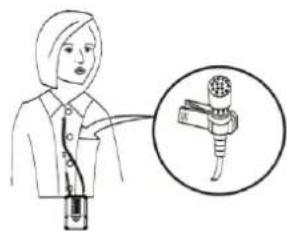
natural_image
Illustration of a person using a handheld device with an inset showing a mechanical component (no text or symbols present)HOOFDMICROFOON
natural_image
Line drawing of a handheld electronic device with a cable and connector (no text or symbols)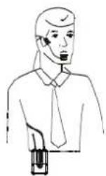
SYSTEEM AANSLUITEN
natural_image
Diagram of a audio equipment setup with two speakers, an audio workstation, and a power outlet (no text or labels)BEDIENING
text_image
8 2 6 5 5 6 1 7 3 4 10 10 4 3 7 Rd UHFnatural_image
Line drawings of two medical devices: a head-mounted ear and a cord with attached sensors (no text or symbols)LAVALIER MIKROFONE
natural_image
Line drawing of a handheld electronic device with a cable and connector (no text or symbols)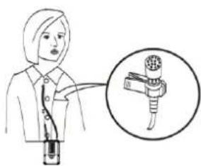
natural_image
Illustration of a person using a handheld device with an inset showing a mechanical component (no text or symbols present)HEADSET MIKROFON
natural_image
Line drawing of a handheld electronic device with a cable and connector (no text or symbols)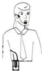
SYSTEMANSCHLÜSSE
text_image
8 2 6 5 5 6 1 7 3 4 10 10 4 3 7 Rd UHF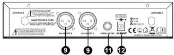
text_image
ANTenna-A www.12345.com Rallyer B Rallyer A UWOL CRED BIP INPUT 9 9 11 12natural_image
Line drawings of two medical devices: a head-mounted device with coiled tubing and a cord with connectors (no text or symbols)CONEXIONES
natural_image
Diagram of a audio recording setup with two speakers, an audio workstation, and a control panel (no text or labels)FUNCIONAMIENTO
The specifications are typical. The actual values can slightly change from one unit to the other. Specifications can be changed without prior notice.
natural_image
Line drawings of a head and ear with attached medical devices (no text or symbols)MICROPHONE CRAVATE
natural_image
Line drawing of a handheld electronic device with a cable and connector (no text or symbols)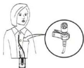
natural_image
Illustration of a person holding a medical device with an inset showing a catheter (no text or symbols present)MICROPHONE SERRE-TETE
natural_image
Line drawing of a handheld electronic device with cable and connector (no text or symbols)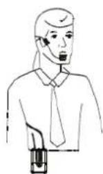
BRANCHEMENTS
CE R&TTE Declaration of Conformity
Importer: TRONIOS BV
Product Description:
Power Dynamics PD781 Wirel.Micro UHF 1x8Ch 1 Micro
Power Dynamics PD782 Wirel.Micro UHF 2x8Ch 2 Micro
Regulatory Requirement: EN 60065 :2002+A1: 2006+A11 :2008
EN 301489-1 :2008-04
EN 301489-9 :2007-11
EN 300422-1 :2008-03
EN 300422-2 :2008-03
EN 62479 :2010
EN 301357-1 :2008-01
EN 301357-2 :2008-01
The product conforms to the essential requirements stated in Directives 2006/95 and 2004/108/EC and other relevant previsions of the R&TTE Directive (1999/5/EC).
ALMELO,
11-02-2015
Signed:
P.Feldman

text_image
Handwritten signature or scribble on white background, possibly a signature or artistic markSpecifications and design are subject to change without prior notice..
www.tronios.com
Copyright © 2015 by TRONIOS the Netherlands