Saga Xpress SX 300 l - Water heater OSO - Free user manual and instructions
Find the device manual for free Saga Xpress SX 300 l OSO in PDF.

| Product Type | Electric storage water heater |
| Brand | OSO |
| Model | Saga Xpress SX 300 l |
| Capacity (persons) | 6.5–7.5 |
| Volume | 287 L (effective) |
| Dimensions (D × H) | ø580 × 1710 mm |
| Weight | 51 kg |
| Power Supply | 1-phase 230 V AC |
| Heating Element | Dual element (3+3 kW or 5+5 kW) |
| Heating Time (Δt 65°C) | 7.2 h (3+3 kW) / 4.8 h (5+5 kW) |
| Max Temperature | 90°C (adjustable thermostat) |
| Mixer Valve | Factory-fitted, adjustable (approx. 40–70°C) |
| Safety Valve | Factory-fitted, 3/4" internal thread |
| Thermostat | Adjustable 60–90°C; safety cut-out at 98°C |
| Inner Tank Material | Stainless steel |
| ErP Class | C |
| Heat Loss | 85 W |
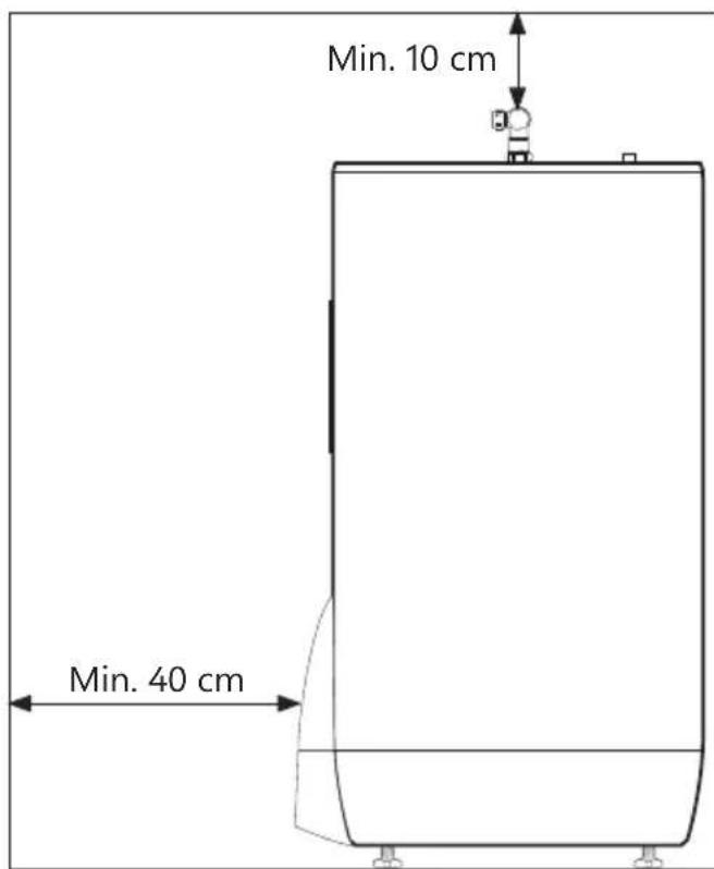
| Installation Clearance | 40 cm front, 10 cm above mixer valve |
| Included Accessories | Top cover, mixer valve, safety valve, adjustable feet, thermostat, heating element |
| Overflow Pipe Requirement | ≥ 18 mm internal diameter, clear, undamaged, frost-free with fall to drain |
| Warranty | 2 years (components), 5 years on stainless steel tank (conditions apply) |
| Maintenance | Annual safety valve inspection; do not set thermostat below 65°C |
Frequently Asked Questions - Saga Xpress SX 300 l OSO
User questions about Saga Xpress SX 300 l OSO
0 question about this device. Answer the ones you know or ask your own.
Ask a new question about this device
Download the instructions for your Water heater in PDF format for free! Find your manual Saga Xpress SX 300 l - OSO and take your electronic device back in hand. On this page are published all the documents necessary for the use of your device. Saga Xpress SX 300 l by OSO.
USER MANUAL Saga Xpress SX 300 l OSO
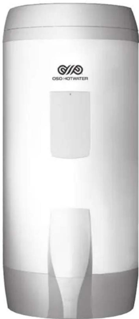
natural_image
Exterior view of a white cylindrical water heater with 'OSO HOTWATER' branding and internal structure (no additional text or symbols)INNHOLDSFORTEGNELSE
1. Sikkerhetsinstruks.... 3
natural_image
Line drawing of a water heater with warning symbol and mounting base (no text or labels)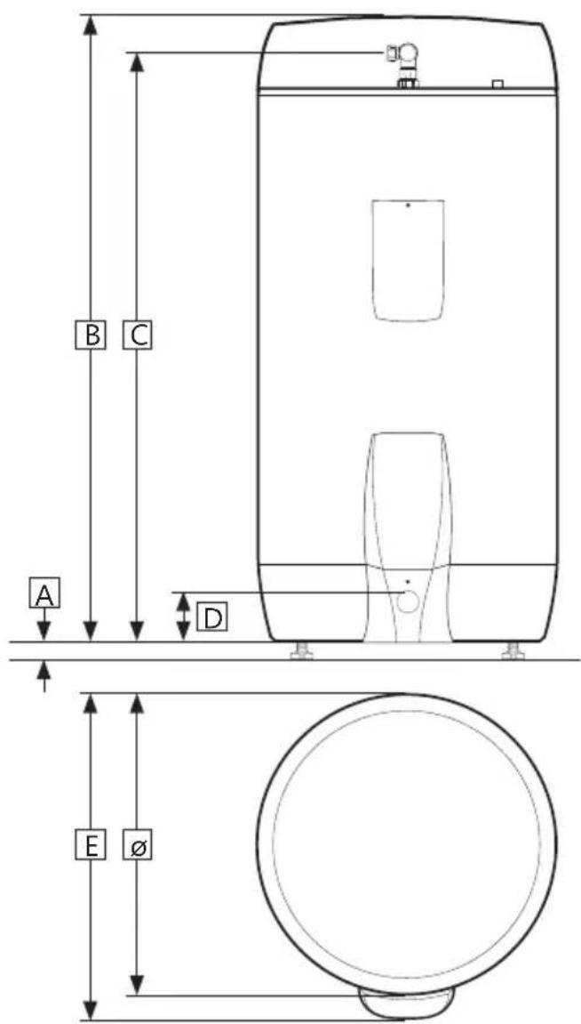
3.3.1 Inntransport
natural_image
Three stylized human figures carrying large boxes, no text or symbols present3.5.5 Montasjeinstruks
3.6 El-installasjon
natural_image
Recycling symbol composed of three chasing arrows forming a triangle (no text or labels)Saga Xpress - SX
150-200-300 l.
SV

natural_image
Exterior view of a cylindrical industrial vessel with visible branding (OSO HOTWATER logo), no readable text beyond branding.SÄKERHETSINFORMATION FDV INFORMATION MONTERINGSANVISNING TDS – TECHNICAL DATA SHEET
INNEHÅLLSFÖRTECKNING
1 Säkerhetsinstruktioner 3
natural_image
Line drawing of a water dispenser with warning symbol and battery casing (no text or labels)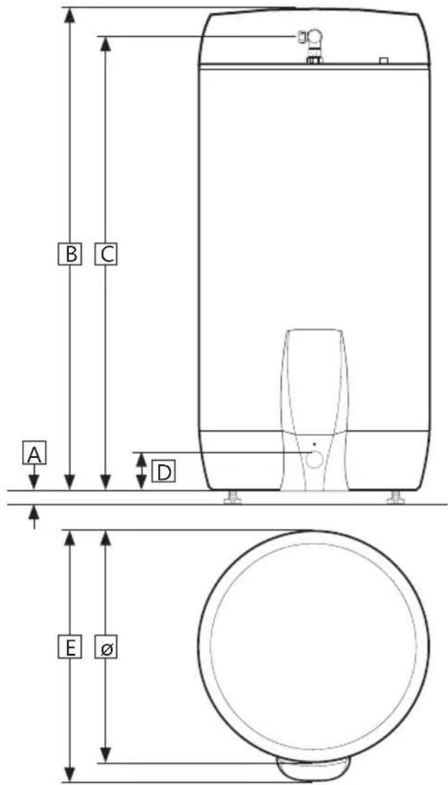
3.3.1 Intransport
natural_image
Three stylized human figures carrying large rectangular blocks, no text or symbols present3.5.5 Monteringsinstruktion
3.6 Elinstallation
Elanslutning, schematisk 5+5 kW
4. IGÅNGSÄTTNING FÖRSTA GÅNGEN
natural_image
Exterior view of a cylindrical industrial vessel with visible branding and internal structure (no readable text beyond logo)SAFETY INFORMATION
O&M INFORMATION
INSTALLATION MANUAL
TDS - TECHNICAL DATA SHEET
CONTENTS
1. Safety instructions .... 3
1.1 General information 3
1.2 Safety instructions for users 4
1.3 Safety instructions for installers ..... 4
2. Product description 5
2.1. Product identification .... 5
2.2. Intended use 5
2.3 CE marking 5
2.4 Technical data 5
2.5. ErP data (TDS) 5
3. Installation instructions 6
3.1. Products covered by these instructions 6
3.2. Included in delivery.... 6
3.3. Product dimensions 6
3.4. Requirements for installation location
3.5. Pipe installation 8
3.6. Electrical installation 10
4. Initial commissioning 12
4.1. Filling with water 12
4.2. Turning on the power 12
4.3. Setting the mixer valve 12
4.4 Control points 12
4.5. Emptying of water 12
4.6. Handover to end-user 12
5. User guide ...... 13
5.1. Settings 13
5.2. Maintenance 13
6. Troubleshooting 14
6.1. Faults and fixes 14
7. Warranty conditions 15
7.1. Warranty and registration 15
7.2. Customer service 15
8. Removing the product 15
8.1. Removal 15
8.2. Returns scheme 15
1. SAFETY INSTRUCTIONS
1.1 General information
- Read the following safety instructions carefully before installing, maintaining or adjusting the water heater.
- Personal injury or material damage may result if the product is not installed or used in the intended manner.
- Keep this manual and other relevant documents where they are accessible for future reference.
- The manufacturer assumes compliance (by the end-user) with the safety, operating and maintenance instructions supplied and (by the installer) with the fitting manual and relevant standards and regulations in effect at the date of installation.

natural_image
Line drawing of a water heater with warning symbol and mounting base (no text or labels)Symbols used in this manual:
| ⚠ WARNING | Could cause serious injury or death |
| ⚠ CAUTION | Could cause minor or moderate injury or damage to property |
| ∅ | DO NOT |
| ! | DO |

This document should be kept in a suitable place where it is accessible for future reference.
1.2 Safety instructions for users
| ⚠ WARNING | |
| ∅ | The overflow from the safety valve must NOT be sealed or plugged. |
| ∅ | The product must NOT be covered over the cover on the front. |
| ∅ | The product must NOT be modified or changed from its original state. |
| ∅ | Children must NOT play with the product or go near it without supervision. |
| ! | The product should be filled with water before the power is switched on. |
| ! | Maintenance/settings should only be carried out by persons over 18 years of age, with sufficient understanding |
| ⚠️ CAUTION | |
| ∅ | The product must not be exposed to frost, over-pressure, over-voltage or chlorine treatment. See warranty provisions. |
| ∅ | Maintenance/settings should not be carried out by persons of diminished physical or mental capacity, unless they have been instructed in the correct use by someone responsible for their safety. |
1.3 Safety instructions for installers
| ⚠ WARNING | |
| ∅ | The overflow from the safety valve must NOT be sealed or plugged. |
| ! | Any overflow pipe from the safety valve MUST be ≥ 18 mm inside, clear, undamaged and frost-free with a fall to the drain. |
| ! | Fixed electric fittings should be used for installation in new homes or when changing an existing electrical setup in accordance with regulations. A mains cable with plug for wall socket can be used when replacing the product without changing the electrical setup. |
| ! | The mains cable should withstand 90°C. A strain reliever must be fitted. |
| ! | The product should be filled with water before the power is switched on. |
| ! | The relevant regulations and standards, and this installation manual, must be followed. |
| ⚠️ CAUTION | |
| 💡 | The product should be placed in a room with a drain, in accordance with the wetroom standard / latest TEK. Alternatively, fit an automatic stop valve with sensor and overflow from safety valve to drain.Liability for consequential damage will only apply if this is followed. |
| 💡 | The product should be properly aligned vertically and horizontally, on a floor or wall suitable for the total weight of the product when in operation. See type plate. |
| 💡 | The product must have a clearance for servicing of 40 cm in front of the cover / 10 cm over the mixer valve. |
2. PRODUCT DESCRIPTION
2.1 Product identification
Identification details for your product can be found on the type plate fixed to the product. The type plate contains details of the product in accordance with EN 12897:2016 and EN 60335-2-21, in addition to other useful data. See Declaration of Conformity at www.osohotwater.com for more information.
OSO products are designed and manufactured in accordance with:
• Pressure vessel standard EN 12897:2016
• Safety standard EN 60335-2-21
• Welding standard EN ISO 3834-2
OSO Hotwater AS is certified for
• Quality ISO 9001
• Environment ISO 14001
• Working environment OHSAS 18001
2.2 Intended use
The Saga series is designed to supply homes with hot running water. The product can be used with alternative energy sources.
2.3 CE marking
CE
The CE mark shows that the product complies with the relevant Directives. See Declaration of Conformity at www.osohotwater.com for more information.
The product complies with standards for:
- Low voltage LVD 2014/35/EU
• Electromagnetic compatibility EMC 2014/30/EU - Pressurised equipment PED 2014/68/EU
Any safety valve(s) used should be CE-marked and comply with the PED 2014/68/EU.
2.4 Technical data
| Prod. no. | Product code: | Capacity persons | Weight kg. | Dia. x Height mm. | Freight vol. m^3 | Volume 40°C water | Heating time hours Δt 65°C |
| 800 0652 | SX 150 - 2+(2) kW/1x230V | 3,5 | 31 | ø580x 950 | 0,38 | 251 | 5,4 |
| 800 0654 | SX 200 - 3+(3) kW/1x230V | 4,5 | 39 | ø580x1260 | 0,47 | 355 | 4,9 |
| 800 0656 | SX 300 - 3+(3) kW/1x230V | 6,5 | 51 | ø580x1710 | 0,63 | 539 | 7,2 |
| 800 0657 | SX 300 - 5+(5) kW/1x230V | 7,5 | 51 | ø580x1710 | 0,63 | 539 | 4,8 |
2.5 ErP data - Technical Data Sheet
| Brand | Model no. | Model name | ErP Rating | Heat loss W | Volume L | |
| OSO Hotwater AS | 800 0652 | Saga Xpress - SX 150 | B | 53 | 143 | |
| OSO Hotwater AS | 800 0654 | Saga Xpress - SX 200 | C | 65 | 194 | |
| OSO Hotwater AS | 800 0656 | Saga Xpress - SX 300 | C | 85 | 287 | |
| OSO Hotwater AS | 800 0657 | Saga Xpress - SX 300 | C | 85 | 287 | |
| Directive: 2010/30/EU Regulation: EU 812/2013 | Directive: 2009/125/EC Regulation: EU 814/2013 | |||||
| Efficiency-tested according to standard: EN 50440: 2015 | ||||||
3. INSTALLATION INSTRUCTIONS
3.1 Products covered by these instructions
800 0652 Saga Xpress - SX 150
800 0654 Saga Xpress - SX 200
800 0656 Saga Xpress - SX 300 - 3+3 kW
800 0657 Saga Xpress - SX 300 - 5+5 kW
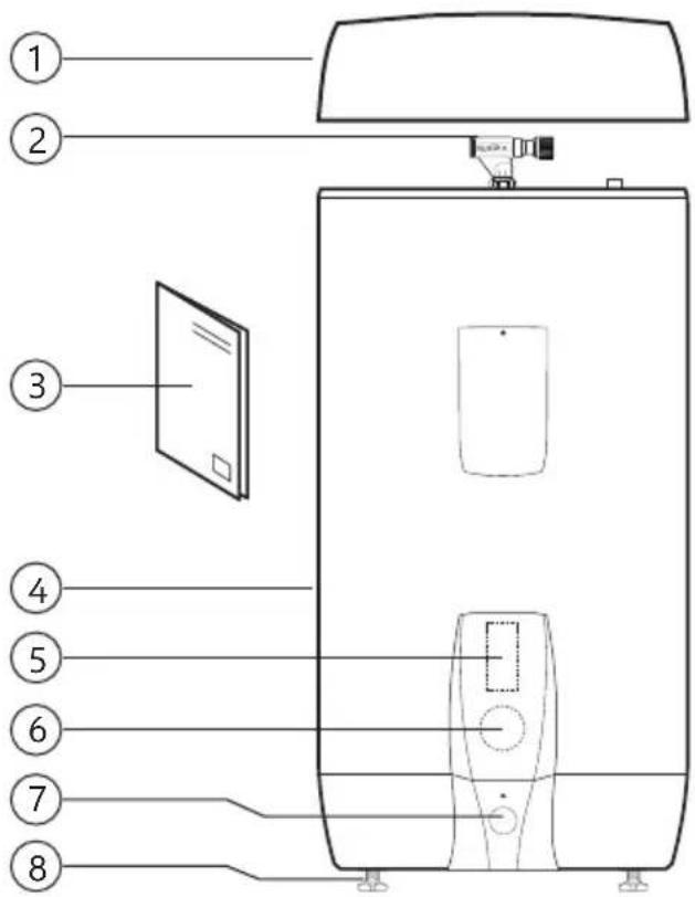
3.2 Included in delivery
| Ref no. | Number of | Description |
| 1 | 1 | Insulated top cover (factory-fitted) |
| 2 1 | Mixer | valve (factory-fitted) |
| 3 1 | Installation manual (this document) | |
| 4 1 | Water heater | |
| 5 1 | Thermostat | |
| 6 1 | Heating element | |
| 7 1 | Safety valve (factory-fitted) | |
| 8 3 | Feet (factory-fitted) | |
3.3 Product dimensions
All dimensions in mm.
| Product. | A | B | C | D | Eø | ||||
| SX 150 | 0 | -40 | 10 | 10 | 960 | 125 | 655 | 580 | |
| SX 200 | 0 | -40 | 12 | 60 | 1210 | 125 | 655 | 580 | |
| SX 300 | 0 | -40 | 17 | 10 | 1660 | 125 | 655 | 580 |
Tolerance +/- 5 mm. (not dimension A).

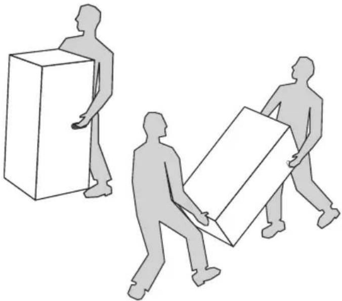
3.3.1 Delivery
The product should be transported carefully as shown, with packaging. Use the handles in the box.
| CAUTION |
| Pipe stubs, valves etc. should not be used to lift the product as this could cause malfunctions. |
natural_image
Three stylized human figures carrying large boxes, no text or symbols present3.4 Requirements for installation location and positioning
| ⚠️ CAUTION | |
| 💡 | The product should be placed in a room with a drain, in accordance with the wetroom standard / latest TEK. Alternatively, fit an automatic stop valve with sensor and overflow from safety valve to drain. |
| 💡 | The product should be placed in a dry and permanently frost-free position. |
| 💡 | The product should be placed on a floor or wall suitable for the total weight of the product when in operation. See type plate. |
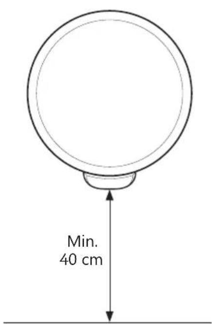
| 💡 | The product must have a clearance for servicing of 40 cm in front of the cover / 10 cm over the mixer valve. |
| 💡 | The product should be easily accessible in the home for servicing and maintenance. |
3.5 Pipe installation
The product is designed to be permanently connected to the mains water supply. Approved pipes of the correct size should be used for installation. The relevant standards and regulations must be followed.
| Product C | W HW | Overflow (2) | Sun / hot water (3) | |
| SX 150 - 300 | 1/2" / ø15 mm ring clamp | 1/2" / ø15 mm ring clamp | 3/4" internal | 1/2" internal |
3.5.1 Incoming water pressure
The efficiency of the product depends on the incoming cold water pressure. The water pressure should be min. 2 bar and max. 6 bar throughout the day. Excessive water pressure can be adjusted by installing a pressure reduction valve.
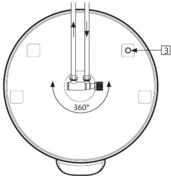
3.5.2 Fitting cold and hot water pipes (CW-HW) and overflow pipes
A) Turn the mixer valve to the desired position.
- Tighten ring clamp to the cylinder (see 3.5.3)
B) CW and HW pipes of a suitable size should be run to the mixer valve and tightened (see 3.5.3)
- For larger pipes, a connector with a 1/2" internal thread can be used.
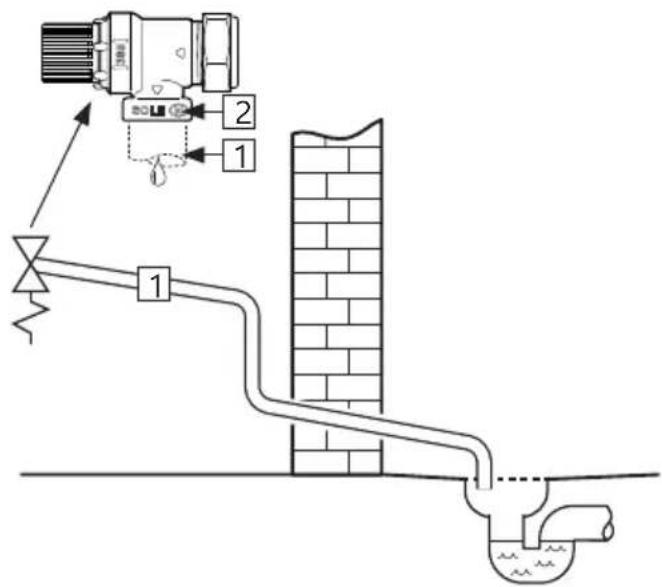
C) Overflow pipe (1)≥ 18 mm inside run to the safety valve;
- Connected to waste 3/4" internal thread.
- Clear, undamaged and frost-free with a fall to the drain.
3.5.3 Connection to solar heating/hot water/HW circulation
The product can be heated with water from solar collectors in accordance with the guidelines in the ErP Directive, using a 1/2" connection (3). OSO can supply an equipment pack designed for alternative energy sources.
1/2" connector (3) can also be used to draw off hot water or for HW circulation.
3.5.4 Torque settings
| Component | Torque |
| Ring clamp connection to CW/HW (ø15) | 40 Nm (+/- 3) |
| Ring clamp connection to cylinder (ø22) | 60 Nm (+/- 5) |
3.5.5 Fitting instructions
| ⚠ WARNING | |
| #! | The product should be filled with water before the power is switched on. |
| #! | Any overflow pipe from the safety valve MUST be ≥ 18 mm inside, clear, undamaged and frost-free with a fall to the drain. |
| ⚠️ CAUTION | |
| 💡 | The product should be placed in a room with a drain, in accordance with the wetroom standard / latest TEK. Alternatively, fit an automatic stop valve with sensor and overflow from safety valve to drain. |
| 💡 | The product should be properly aligned vertically and horizontally, on a floor or wall suitable for the total weight of the product when in operation. See type plate. |
| 💡 | The product must have a clearance for servicing of 40 cm in front of the cover / 10 cm over the mixer valve. |
3.5.6 Installation recommendation
| RECOMMENDATION | |
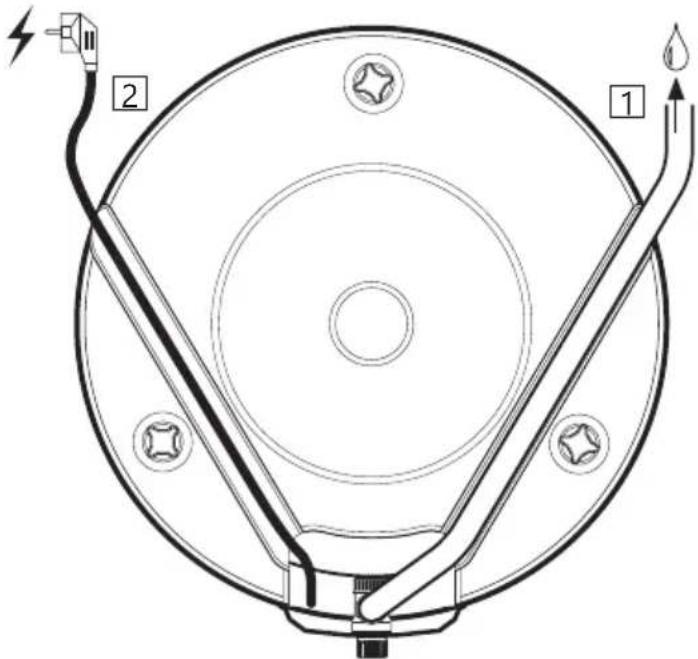
| - | Allow clearance to the floor. Screw the feet out a minimum of 15 mm from the bottom of the product. |
| - | Overflow pipe from the safety valve to the drain (1) and mains cable for wall socket (2) should be hidden under the channels in the bottom of the product. |
| - | If the non-return valve is tight, a reduction valve and expansion vessel should be fitted (to stop dripping from the safety valve). |
| - | If the maximum water pressure exceeds 6 bar in a 24-hour period, a reduction valve and expansion vessel should be fitted. |
| - | For installation in a rooms which does not conform to the wetroom standard, a watertight drip tray with overflow pipe ≥ 18 mm. inside diameter should be fitted under the product, in addition to an automatic stop cock with sensor. This will prevent possible material damage. |
3.6 Electrical installation
Fixed electric fittings should be used for installation in new homes or when changing an existing electrical setup in accordance with regulations. A mains cable with plug for wall socket can be used when replacing the product without changing the electrical setup. Any fixed electric fittings must be installed by an authorised electrician. The relevant standards and regulations must be followed.
3.6.1 Electrical components
| Component Note | |
| Safety thermostat 98°C thermal cut-out | |
| Work thermostat 60-90°C adjustable | |
| Heating element 1-phase 230 V | |
| Mains cable with plug Heat-resistant | |
| Internal wires | Heat-resistant |
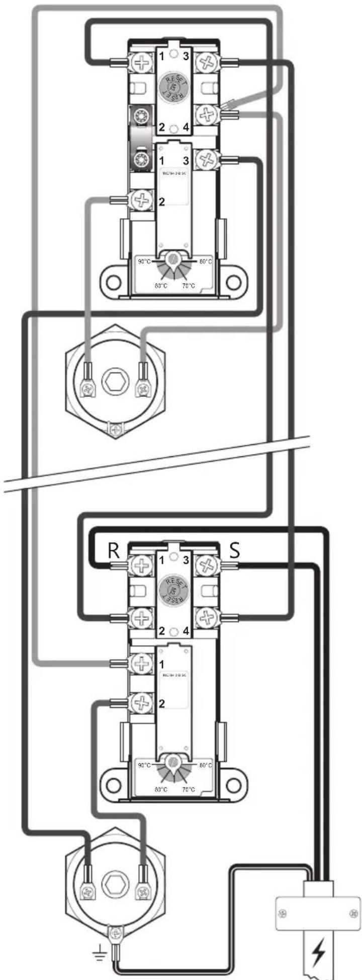
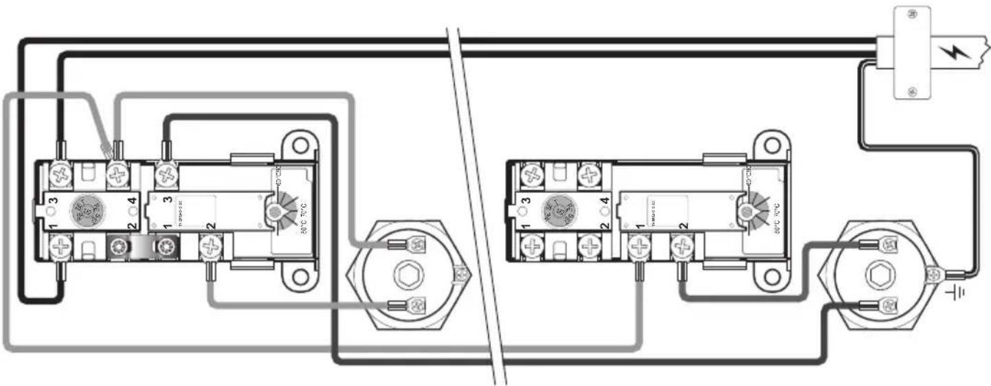
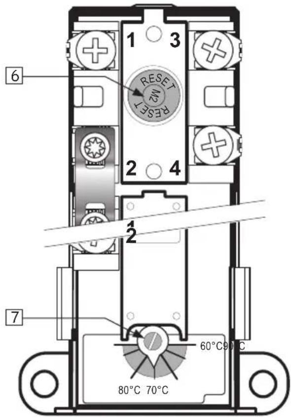
3.6.2 Electrical connections in the junction box
WARNING
Constant voltage present at terminals R and S. Before any electrical work is done, the power supply must be disconnected and secured against activation while the work is in progress.
A) Blue wire (R) – Neutral – connected to point '1' on the lower safety thermostat.
B) Brown wire (S) – Live – connected to point '3' on the lower safety thermostat.
C) Yellow wire with green stripe ⏻ – Earth – connected to the terminal for the heating element in the lower panel (hexagonal brass)
D) Internal wires from the element to the thermostat are connected to point '3' on the safety thermostat and point '2' on the operating thermostat. See illustration.
3.6.3 Torque settings
| Component Torque | |
| 5/4" heating element 60 Nm (+/- 5) | |
| Thermostat screws 2 Nm (+/- 0.1) | |
| Screw on the element head 2 Nm (+/- 0.1) | |
Electrical connection, diagram 2+2 & 3+3 kW
3.6.4 Fitting instructions
| ⚠ WARNING | |
| 💡 | The product should be filled with water before the power is switched on. |
| 💡 | Fixed electric fittings should be used for installation in new homes or when changing an existing electrical setup in accordance with regulations. A mains cable with plug for wall socket can be used when replacing the product without changing the electrical setup. |
| 💡 | The mains cable should withstand 90°C. A strain reliever must be fitted. |
| △ CAUTION | |
| ! | The product must have a clearance for servicing of 40 cm in front of the cover / 10 cm over the mixer valve. |
| ! | In case of damage to the mains cable and plug, it should be replaced with a specially adapted mains cable from the manufacturer. |
3.6.5 Fitting recommendation
| RECOMMENDATION | |
| - | The mains cable supplied should be used with fixed electric fittings by removing the plug for the wall socket. (Heat-resistant) |
| - | Mains cable for wall socket/wall box should be hidden under one of the channels in the bottom of the product. |
| - | For products with ≤ 2kW capacity, a ≥ 10A fuse / ≥ 1.5\# wire should be used*. For products with ≤ 3kW capacity, a ≥ 15A fuse / ≥ 2.5\# wire should be used*. For products with ≤ 5kW capacity, the power supply should be specified according to NEK 400*. |
*This product is described with an output of 2+2, 3+3 or 5+5 kW. This states that the product is fitted with two elements each with the stated output, but the product never draws
more than 2, 3 or 5 kW respectively as the power supply is swiched between the two elements as needed. The two elements will never be connected at the same time.
Electrical connection, diagram 5+5 kW
4. INITIAL COMMISSIONING
4.1 Filling with water
First check that all pipes are connected correctly. Then proceed as follows:
A) Open a hot tap – leave it open
B) Turn the adjustable knob on the mixer valve all the way to '+'
C) Open the cold water supply to the product.
Check that the water from the open hot water tap is flowing freely, without any air locks.
A) Close hop tap.
4.2 Turning on the power
When the cylinder has been filled with water, the power can be switched on.
A) Insert plug into specified wall socket or turn on switch/breaker.
4.3 Setting the mixer valve
The outgoing hot water temperature from the product to the taps in the home can be adjusted with the knob on the mixer valve. Adjusting the mixer valve does not affect the temperature of the hot water in the product.
To adjust the temperature:
A) Turn the adjustable knob (1) all the way to '+'
B) Then turn the knob towards '-' to the desired temperature.
| Turns Temperature | 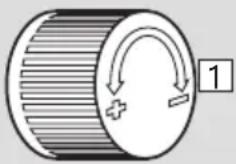 |
| 0 Approx. 70°C | |
| 1/4 Approx. 60°C | |
| 1/2 Approx. 50°C | |
| 3/4 Approx. 40°C |
4.4 Control points
A) Check that all pipe connections to/from the product are tight and not leaking.
B) Check that the power supply to the product is not at risk of exposure to mechanical, thermal or chemical damage.
C) Check that any overflow pipe from the safety valve is clear, undamaged and frost-free with a fall to the drain.
D) Check that the product is standing firmly vertically and horizontally.
4.5 Emptying of water
| ⚠ WARNING |
| The water temperature in the product can exceed 75°C and could cause scalding. Before emptying, a hot tap should be opened to the max. pressure/temperature for min. 3 minutes. |
A) Disconnect the power supply.
B) Shut off incoming cold water supply.
C) Open a hot tap to the maximum – leave open (prevents vacuum).
D) Open the mixer valve all the way to '+'.
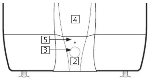
E) Remove the cover from the safety valve (2) by loosening the screw (5).
F) Turn the knob on the safety valve (3) approx. 90 degrees to the open position. Product empties.
After emptying, close the safety valve by turning the knob (3) further clockwise. Close all open taps. Adjust the mixer valve to its original setting. Fit the cover (2) ahead of the safety valve.
If the tank needs to be emptied faster, the safety valve can be removed by unscrewing the clamping rung connector to the waste pipe. When re-fitting, the ring clamp connection should be tightened to 60 Nm torque (+/-5).
4.6 Handover to end-user
| THE INSTALLER MUST: |
| Brief the end-user on safety and maintenance instructions. |
| Brief the end-user on settings and emptying the product. |
| Hand this installation manual over to the end-user. |
| Enter contact details on the type plate on the product. |
5. USER GUIDE
5.1 Settings
5.1.1 Thermostat setting
The thermostat on the product is adjustable from 60-90°C. The thermostat should not be set lower than 65°C to prevent bacteria growth. To adjust the temperature:
A) Disconnect the power supply.
B) Remove the covers (4) on the front with a screwdriver.
C) Adjust the temperatures on the thermostat (7) with a screwdriver.
Fit the covers (4) before connecting the power supply. Changing the temperature setting on the thermostats only changes the temperature of the water in the tank. Temperature to the taps is adjusted on the mixer valve.
5.1.2 Resetting the safety thermostat
The safety thermostat on the product cuts out when there is a risk of overheating. This is reset by removing the cover (4) and pressing the red 'RESET' button (6). If the thermostat cuts out repeatedly, contact the installer.
5.1.3 Setting the mixer valve
The outgoing hot water temperature from the product to the taps in the home can be adjusted with the knob on the mixer valve. To adjust the temperature:
A) Turn the adjustable knob (1) all the way to '+'
B) Then turn the knob towards '-' to the desired temperature.
5.1.4 Adjusting the feet
The product is equipped with three factory-fitted feet, adjustable from 0-40 mm. Screw the feet out a minimum of 15 mm from the bottom of the product. Adjust the feet individually until the product is standing firmly vertically and horizontally.
WARNING
Constant voltage present in the junction box. Before any electrical work is done, the power supply must be disconnected and secured against activation while the work is in progress.
| Turns Temperature | 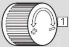 |
| 0 Approx. 70°C | |
| 1/4 Approx. 60°C | |
| 1/2 Approx. 50°C | |
| 3/4 Approx. 40°C |
5.2 Maintenance
| MAINTENANCE INSTRUCTIONS | ||
| ! | Maintenance should be carried out by persons over 18 years of age, with sufficient understanding | 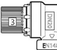 |
| ! | Annual inspection of safety valve: | |
| - | Open valve for 1 min. by turning the knob (3) approx. 90 degrees to the open position. | |
| - Visually check that the water is flowing freely to the drain. | ||
| - | YES = OK. Close the valve by turning the knob (3) a further 90 degrees to the closed position. | |
| - | NO = NOT OK. Disconnect power supply / shut off water supply. Contact installer. | |
6. TROUBLESHOOTING
6.1 Faults and fixes
If problems arise when the product is in use, check for possible faults and fixes in the table. If the problem is not shown in the troubleshoot-
ing table or you are unsure what is wrong, contact the installer (see type plate on the product) or OSO Hotwater AS - see section 7.2.
| TROUBLESHOOTING | ||
| Problem Possible cause of | fault Possible solution | |
| There is leakage/dripping from the safety valve/there is often water on the floor by the cylinder in the morning | Pressure reduction valve, water meter or blocked non-return valve on the water intake.Water pressure into the home is too high. | Fit AX expansion vessel with absorbs expansion during heating, and fit pressure reduction valve for stable water pressure inside the home. The pressure reduction valve is adjusted in according to the pressure in the expansion vessel. Contact auth. installer. |
| The safety valve is worn or there are particles stuck between the membrane and the valve seat because the water is dirty | Try to flush with water through the safety valve. Open valve approx. 1 minute. See section 5.2. If the valve still leaks, it must be replaced. Contact auth. installer. | |
| Leak from heating element. | Verify as follows: a) cut the electric supply, b) unscrew the cover, c) visually check whether there is a leak from the heating element. If so, replace the gasket/heating element. Contact auth. installer. | |
| No hot water | Power supply interrupted. | Verify that the fuse is on / the plug is plugged in to the wall contact / the earth breaker has not tripped. |
| Thermostat has cut out. | Press the 'RESET' button on the safety thermostat; see 'User guide'. | |
| Heating element is defective. | Replace heating element. Contact auth. installer. | |
| Leak in hot water pipe | Verify as follows: a) close the mixer valve, b) wait 2-3 hours, c) feel the mixer valve to see whether it is hot. If so, there is a leak in the hot water pipe or elsewhere. Contact auth. installer. | |
| Not enough hot water High consumption in the home. | Raise the temperature on the thermostat to 85°C; see 'User guide'.Switch to a larger OSO water heater. Contact auth. installer. | |
| Not high enough temperature | The mixer valve is set for low temperatures. | Raise the temperature on the mixer valve; see 'User guide'. |
| The thermostat is set for low temperatures. | Raise the temperature on the thermostat to 85°C; see 'User guide'. | |
| Change from cold to hot water in taps. | Contact auth. installer. | |
| Fuse/earth breaker trips repeatedly | Possible fault in the heater's electrical system. | Verify as follows: a) cut the electric supply, b) unscrew the cover, c) visually check the junction box for any problems. If so, contact auth. installer to check. Fit the cover. |
| Long time before the water reaches the tap | Long stretch of pipe from water heater to tap. | Fit circulation wire or heating cable to HW pipe. Or fit an auxiliary heater by the tap. Contact auth. installer. |
| Knocking in the pipes when the hot tap is closed | Large pressure increase when the tap is closed quickly. | Completely normal. Fit AX expansion vessel if troublesome. Contact auth. installer. |
7. WARRANTY CONDITIONS
1. Scope
OSO Hotwater AS (hereinafter called OSO) warrants for 2 years from the date of purchase, that the Product will: i) conform to OSO specification, ii) be free from defects in materials and workmanship, subject to conditions below. All components carry a 2-year warranty.
The warranty is voluntarily extended by OSO to 5 years for the stainless steel inner tank. This extended warranty only applies to Products purchased by a consumer, that has been installed for private use and that has been distributed by OSO or by a distributor where the Products have been originally sold by OSO. The extended warranty does not apply to Products purchased by commercial entities or for Products that have been installed for commercial use. These shall be subject only to the mandatory provisions of the law. The conditions and limitations set out below shall apply.
2. Coverage
If a defect arises and a valid claim is received within the statutory warranty period, at its option and to the extent permitted by law, OSO shall either; i) repair the defect, or; ii) replace the product with a product that is identical or similar in function, or; iii) refund the purchase price.
If a defect arises and a valid claim is received after the statutory warranty period has expired, but within the extended warranty period, OSO will supply a product that is identical or similar in function. OSO will in such cases not cover any other associated costs.
Any exchanged Product or component will become the legal property of OSO. Any valid claim or service does not extend the original warranty. The replacement Product or part does not carry a new warranty.
3. Conditions
The Product is manufactured to suit most public water supplies. However, there are certain water chemistries (outlined below) that can have a detrimental effect on the Product and its life expectancy. If there are uncertainties regarding water quality, the local water supply authority can supply the necessary data.
The warranty applies only if the conditions set out below are met in full:
- The Product has been installed by a professional installer, in accordance with the instructions in the installation manual and all relevant Codes of Practice and Regulations in force at the time of installation.
- The Product has not been modified in any way, tampered with or subjected to misuse and no factory fitted parts have been removed for unauthorized repair or replacement.
- The Product has only been connected to a domestic mains water supply in compliance with the European Drinking Water Directive EN 98/83 EC, or latest version. The water
7.1 Customer service
In case of problems that cannot be resolved with the aid of the troubleshooting guide in this installation manual, contact either:
A) The installer who supplied the product.
B) OSO Hotwater AS: Tel.: +47 32 25 00 00 oso@oso.no / www.oso.no
8. REMOVING THE PRODUCT
8.1 Removal
A) Disconnect the power supply.
B) Shut off incoming cold water supply.
C) Empty the product of water – see section 4.4.
should not be aggressive, i.e. the water chemistry shall comply with the following:
- Chloride < 250 mg / L
- Electric Conductivity (EC) @25°C < 750 uS / cm
- Saturation Index (LSI) @80°C > - 1,0 / < 0,8
- pH level >6,0/<9,5
- The immersion heater has not been exposed to hardness levels exceeding 10^ (180 ppm CaCO3). A water softener is recommended in such cases.
• Any disinfection has been carried out without affecting the Product in any way whatsoever. The Product shall be isolated from any system chlorination.
• The Product has been in regular use from the date of installation. If the Product is not intended to be used for 60 days or more, it must be drained.
- Service and/or repair shall be done according to the installation manual and all relevant codes of practice. Any replacement parts used shall be original OSO spare parts.
- Any third-party costs associated with any claim has been authorized in advance by OSO in writing.
- The purchase invoice and/or installation invoice, a water sample as well as the defective product is made available to OSO upon request.
Failure to follow these instructions and conditions may result in product failure, and water escaping from the Product.
4. Limitations
The warranty does not cover:
- Any fault or costs arising from incorrect installation, incorrect application, lack of regular maintenance in accordance with the installation manual, neglect, accidental or malicious damage, misuse, any alteration, tampering or repair carried out by a non-professional, any fault arising from the tampering with or removal of any factory fitted safety components or measures.
- Any consequential damage or any indirect loss caused by any failure or malfunction of the Product whatsoever.
- Any pipework or any equipment connected to the Product.
- The effects of frost, lightning, voltage variation, lack of water, dry boiling, excess pressure or chlorination procedures.
- The effects of stagnant (de-aerated) water if the Product has been left unused for more than 60 days consecutively.
- Damage caused during transportation. Buyer shall give the carrier notice of such damage.
- Costs arising if the Product is not immediately accessible for servicing.
These warranties do not affect the Buyer's statutory rights.
D) Disconnect all pipes.
E) The product can now be removed.
8.2 Returns scheme
This product is recyclable and should be taken to the environmental recycling centre. If the product is to be replaced with a new one, the installer can take the old cylinder away for recycling.

natural_image
Recycling symbol composed of three chasing arrows forming a triangle (no text or labels)Saga Xpress - SX
150-200-300 l.
FR

natural_image
Exterior view of a cylindrical industrial water heater with visible branding (OSO HOTWATER logo)INFORMATIONS DE SÉCURITÉ INFORMATIONS FDV INSTRUCTIONS DE MONTAGE FT - FICHE TECHNIQUE
SOMMAIRE
natural_image
Line drawing of a water heater with warning symbol and mounting base (no text or labels)
3.3.1 Transport
natural_image
Three stylized human figures carrying large rectangular blocks, no text or symbols presentnatural_image
Exterior view of a cylindrical industrial vessel with visible branding (OSO HOTWATER logo), no readable text beyond branding.VEILIGHEIDSINFORMATIE
INFORMATIE OVER BEHEER, GEBRUIK EN ONDERHOUD
INSTALLATIE-INSTRUCTIES
natural_image
Line drawing of a water dispenser with warning symbol and battery casing (no text or labels)2. PRODUCTBESCHRIJVING
2.1 Productidentificatie

3.3.1 Transport
natural_image
Three stylized human figures carrying large boxes, no text or symbols present3.6 Elektrische installatie
natural_image
Abstract black and white decorative swirl pattern with no text or symbolsOSO HOTWATER
OSO Hotwater AS
Industriveien 1
© This installation manual and all its content is protected by copyright and may be reproduced or distributed only with written consent from the manufacturer. We reserve the right to make changes without notice.
Saga Xpress - SX
150-200-300 л.
RU
natural_image
Exterior view of a cylindrical industrial vessel with visible branding (OSO HOTWATER logo), no readable text beyond branding.natural_image
Line drawing of a water dispenser with warning symbol and mounting base (no text or labels)
natural_image
Three stylized human figures carrying large rectangular blocks, no text or symbols present3.6 Электромонтаж
natural_image
Diagram of a cylindrical object with internal striped pattern and curved arrows indicating rotation or movement (no text or symbols)3300 Hokksund - Norway
Tel: +47 32 25 00 00
oso@oso.no
www.osohotwater.com
© This installation manual and all its content is protected by copyright and may be reproduced or distributed only with written consent from the manufacturer. We reserve the right to make changes without notice.