
360 CFX 3S - Remote control toy Blade - Free user manual and instructions
Find the device manual for free 360 CFX 3S Blade in PDF.

| Product type | RC 3D Helicopter |
| Brand / Model | Blade 360 CFX 3S |
| Length | 670 mm |
| Main rotor diameter | 810 mm |
| Tail rotor diameter | 175 mm |
| Height | 215 mm |
| Flight weight | 850 g |
| Power source | LiPo battery 3S 11.1V 3000mAh 30C |
| Motor | Outrunner brushless 3400Kv |
| Flight controller | Spektrum AR636A AS3X (flybarless) |
| ESC | 45A Brushless with BEC |
| Cyclic servos | Digital 12g metal gear |
| Tail servo | Digital 12g metal gear |
| Compatible transmitter | Spektrum DSM2/DSMX (DX6i or higher) |
| Main features | Hovering, forward flight, aerobatic flight (3D), constant speed governor |
| Maintenance and cleaning | Clean with a soft brush or dry cloth; check ball joints, bearings, blades, and fasteners after each flight |
| Safety | Keep a safe distance, use throttle lock, cut power before handling, do not fly indoors |
| Spare parts and repairability | Spare and optional parts available; mechanical repairs to be performed by the user, electronic repairs by Horizon Hobby |
| Warranty | Limited 6-month warranty (depending on country) against manufacturing defects |
Frequently Asked Questions - 360 CFX 3S Blade
User questions about 360 CFX 3S Blade
0 question about this device. Answer the ones you know or ask your own.
Ask a new question about this device
Download the instructions for your Remote control toy in PDF format for free! Find your manual 360 CFX 3S - Blade and take your electronic device back in hand. On this page are published all the documents necessary for the use of your device. 360 CFX 3S by Blade.
USER MANUAL 360 CFX 3S Blade
All instructions, warranties and other collateral documents are subject to change at the sole discretion of Horizon Hobby, LLC. For up-to-date product literature, visit horizonhobby.com and click on the support tab for this product.
Meaning of Special Language
The following terms are used throughout the product literature to indicate various levels of potential harm when operating this product:
NOTICE: Procedures, which if not properly followed, create a possibility of physical property damage AND a little or no possibility of injury.
CAUTION: Procedures, which if not properly followed, create the probability of physical property damage AND a possibility of serious injury.
WARNING: Procedures, which if not properly followed, create the probability of property damage, collateral damage, and serious injury OR create a high probability of superficial injury.

WARNING: Read the ENTIRE instruction manual to become familiar with the features of the product before operating. Failure to operate the product correctly can result in damage to the product, personal property and cause serious injury.
This is a sophisticated hobby product. It must be operated with caution and common sense and requires some basic mechanical ability. Failure to operate this Product in a safe and responsible manner could result in injury or damage to the product or other property. This product is not intended for use by children without direct adult supervision. Do not use with incompatible components or alter this product in any way outside of the instructions provided by Horizon Hobby, LLC. This manual contains instructions for safety, operation and maintenance. It is essential to read and follow all the instructions and warnings in the manual, prior to assembly, setup or use, in order to operate correctly and avoid damage or serious injury.
Age Recommendation: Not for children under 14 years. This is not a toy.
Safety Precautions andWarnings
- Always keep a safe distance in all directions around your model to avoid collisions or injury. This model is controlled by a radio signal subject to interference from many sources outside your control. Interference can cause momentary loss of control.
- Always operate your model in open spaces away from full-size vehicles, traffic and people.
- Always carefully follow the directions and warnings for this and any optional support equipment (chargers, rechargeable battery packs, etc.).
- Always keep all chemicals, small parts and anything electrical out of the reach of children.
- Always avoid water exposure to all equipment not specifically designed and protected for this purpose. Moisture causes damage to electronics.
-
Never place any portion of the model in your mouth as it could cause serious injury or even death.
-
Never operate your model with low transmitter batteries.
- Always keep aircraft in sight and under control
Always move the throttle fully down at rotor strike.
Always use fully charged batteries. - Always keep transmitter powered on while aircraft is powered.
Always remove batteries before disassembly. - Always keep moving parts clean.
Always keep parts dry. - Always let parts cool after use before touching.
Always remove batteries after use. - Never operate aircraft with damaged wiring.
- Never touch moving parts.

WARNING AGAINST COUNTERFEIT PRODUCTS: If you ever need to replace a Spektrum component found in a Horizon Hobby product, always purchase from Horizon Hobby, LLC or a Horizon Hobby authorized dealer to ensure authentic high-quality Spektrum product. Horizon Hobby, LLC disclaims all support and
warranty with regards, but not limited to, compatibility and performance of counterfeit products or products claiming compatibility with DSM or Spektrum technology.
As of this printing, you are required to register with the FAA if you own this product. For up-to-date information on how to register with the FAA, please visit https://registermyuas.faa.gov/. For additional assistance on regulations and guidance on UAS usage, visit knowbeforeyoufly.org/.
Box Contents:
- Blade 360 CFX 3S
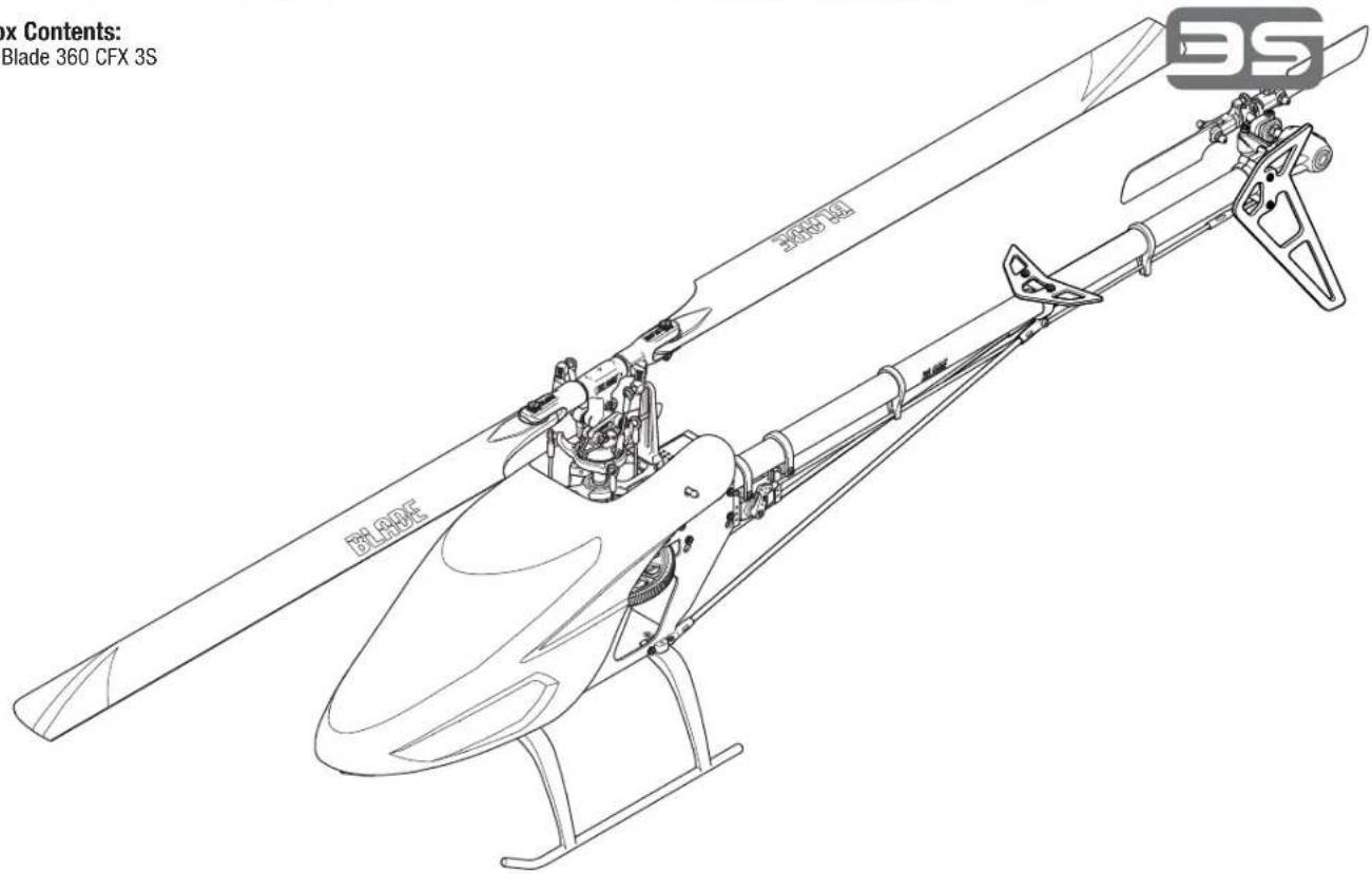
Table of Contents
First Flight Preparation 4
Flying Checklist 4
Low Voltage Cutoff (LVC) 4
Transmitter Setup 4
Installing the Flight Battery 6
Transmitter and Receiver Binding 6
Throttle Hold 6
Control Tests 7
Pre-Flight Checklist 8
Flying the Blade 360 CFX 3S 8
Gyro Gain Adjustment
Blade Helicopter Belt Tension 8
Post-Flight Inspections and Maintenance 9
Troubleshooting Guide 12
Limited Warranty 12
Warranty and Service Contact Information 13
Compliance Information for the European Union 13
FCC Information 13
IC Information 13
Exploded Views. 50
Parts List 52
Optional Parts 53
| Specifi cations | |||
| Length | 26.4 in (670mm) | Tail Rotor Diameter | 6.9 in (175mm) |
| Height | 8.5 in (215mm) | Flying Weight | 30 oz (850 g) |
| Main Rotor Diameter | 31.89 in (810mm) | ||
| Included Components Required Components | |
| Airframe | Blade® 360 CFX 3S |
| Motor | Brushless Outrunner, 3400 Kv |
| Receiver | Spektrum™ AR636A AS3X® |
| ESC | 45-Amp Brushless ESC |
| Swash Servos | Digital Cyclic Servo 12 g Metal Gear |
| Tail Servo | Digital Tail Servo 12 g Metal Gear |
| Battery | 3000 mAh 3S 11.1V 30C LiPo (EFLB30003S30) |
| Charger | Li-Po Balancing Charger |
| Transmitter | Full Range DSM2®/DSMX® technology transmitter (DXe and up) |
To receive product updates, special offers and more, register your product at www.bladehelis.com
First Flight Preparation
- Remove and inspect cor
- Charge the flight battery
- Install the flight battery in the helicopter (once it has been fully charged)
- Program your computer transmitter
- Bind your transmitter
Familiarize yourself with the controls
Find a suitable area for flying
Flying Checklist
Always turn the transmitter on first
Turn throttle hold On
Plug the flight battery into the lead from the ESC
Allow the ESC to initialize and arm properly
Perform control test
Place the model onto flat ground at least 10 meters from the pilot. Ensure the area is free from obstructions
Fly the model
Land the model
Unplug the flight battery from the ESC
Always turn the transmitter off last
Low Voltage Cutoff (LVC)
The ESC will continuously lower power to the motor until complete shutdown when the battery reaches 9V under load. This helps prevent over-discharge of the Li-Po battery. Land immediately when the ESC activates LVC. Continuing to fly after LVC can damage the battery, cause a crash or both. Crash damage and batteries damaged due to over-discharge are not covered under warranty.
Repeatedly flying the helicopter until LVC activates will damage the helicopter battery.
Disconnect and remove the Li-Po battery from the aircraft after use to prevent trickle discharge. During storage, make sure the battery charge does not fall below 3V per cell.
Electronic Speed Controller Governor Operation
The Blade 360 CFX 3S Electronic Speed Controller (ESC) utilizes a head speed governor to maintain a constant head speed during flight. The governor will work to maintain a constant head speed throughout maneuvers and the discharge cycle of the flight battery.
The throttle position determines the requested head speed, and although throttle curves are still used, they will be a constant value; all positions of the curve are set to the same value. The lowest position of the normal flight mode throttle curve must be set to 0 to ensure the motor can be disabled.
The default throttle curve settings listed in the transmitter setup tables should be acceptable to most pilots and we recommend starting with these values. If you feel an adjustment is necessary after a few flights, adjust the throttle percentage for the desired flight mode. We recommend making small changes of 5% to find your preferred head speed.
Remember the throttle position on the transmitter is simply requesting a specific head speed and this is not related to the actual motor power percentage.
Transmitter Setup
Program your transmitter before attempting to bind or fly the helicopter. Always start by creating a new model in the transmitter to ensure no existing settings are inadvertently used. Transmitter programming values are shown below for the
Spektrum Transmitters. The files for models using Spektrum™ transmitters with Spektrum AirWare™ software are also available for download online at www.spektrumrc.com.
DXe
To use the Spektrum™ DXe transmitter, download the Blade® 360 CFX 3S DXe model setup available at www.spektrumrc.com or use the appropriate programming cable and the PC or mobile app to program the transmitter.
DX6i
SETUP LIST
| Model Type | HELI | |
| Swash Type | 1 servo 90 | |
| REVERSE | ||
| Channel | Direction | |
| THRO | N | |
| AILE | N | |
| ELEV | N | |
| RUDD N | ||
| GYRO N | ||
| PITC | R | |
| Modulation Type | ||
| AUTO DSMX-ENABLE | ||
| D/R COMBI | ||
| D/R SW | AILE | |
| Timer | ||
| Down Timer 4:00 | ||
| Switch THR CUT | ||
ADJUST LIST
| TRAVEL ADJ | |
| Channel | Travel |
| THRO | 100/100 |
| AILE | 100/100 |
| ELEV | 100/100 |
| RUDD | 100/100 |
| GYRO | 100/100 |
| PITC | 100/100 |
| D/R & Expo | |
| Chan Sw Pos D/R Exp | |
| AILE | 0 |
| 1 | |
| ELEV | 0 |
| 1 | |
| RUDD | 0 |
| 1 | |
| 100 0 | ||
| 8 | 5 | |
| 100 0 | ||
| 8 | 5 | |
| 100 0 | ||
| 8 | 5 |
Throttle Curve
| Switch Pos (F Mode) | Pos 1 Pos | Pos 2 Pos | Pos 3 Pos | Pos 4 Pos | 5 | |
| NORM 0 50 | 50 | 50 | 50 | |||
| STUNT* | 65 | 65 | 65 | 65 | 65 |
| GYRO | |||
| RATE | SW-F.MODE | ||
| 0 | 60% | NORM | 0 |
| 1 | 50% | STUNT | 1 |
Pitch Curve
| Switch Pos (F Mode) | Pos 1 | Pos 2 | Pos 3 | Pos 4 | Pos 5 | |
| NORM | 25 | 37 | 50 | 75 | 100 | |
| STUNT 0 25 | 50 | 75 | 100 | |||
| HOLD | 25 | 37 | 50 | 75 | 100 |
DX7s, DX8
| SYSTEM SETUP | |
| Model Type HELI | |
| Swash Type 1 servo 90 | |
| F-Mode Setup | |
| Flight Mode F Mode | |
| Hold Hold | |
| SW Select | |
| Trainer | Aux 2 |
| F Mode | Gear |
| Gyro | INH |
| Mix | INH |
| Hold | INH |
| Knob INH | |
| Frame Rate | |
| 11ms | |
| DSMX | |
FUNCTION LIST
| Servo Setup | |||||
| Chan | Travel | Reverse | Chan | ||
| THR | 100/100 | Normal | GER | ||
| AIL | 100/100 | Normal | PIT | ||
| ELE | 100/100 | Normal | AX2 | ||
| RUD 100/100 Normal | |||||
| D/R & Expo | |||||
| Chan | Switch Pos (Ail D/R) D/R | Expo | |||
| AILE | 0 100/100 0 | ||||
| 1 85/85 0 | |||||
| 2 85/85 0 | |||||
| ELEV | 0 100/100 0 | ||||
| 1 85/85 0 | |||||
| 2 85/85 0 | |||||
| RUDD | 0 100/100 0 | ||||
| 1 85/85 0 | |||||
| 2 85/85 0 | |||||
| Throttle Hold | |||||
| Throttle 0% | |||||
| Travel | Reverse |
| 100/100 | Normal |
| 100/100 | Normal |
| 100/100 | Normal |
| Timer | |
| Mode Count Down | |
| Time 4:00 | Tone |
| Start Throttle Out | |
| Over 25% | |
FUNCTION LIST
| Servo Setup | |||||
| Chan | Travel | Reverse | Chan | Travel | Reverse |
| THR | 100/100 | Normal | PIT | 100/100 | Normal |
| AIL | 100/100 | Normal | AX2* | 100/100 | Normal |
| ELE | 100/100 | Normal | AX3* | 100/100 | Normal |
| RUD 100/100 | Normal | AX4* | 100/100 | Normal | |
| GER | 100/100 | Normal | |||
| Timer | |
| Mode Count Down | |
| Time | 4:00 |
| Start | Throttle Out |
| Over | 25% |
| One Time | Inhibit |
DX6G2, DX6e, DX7G2, DX8G2, DX9, DX18, DX20
| MODEL Type | HELI |
| Swash Type | Normal |
| F-Mode Setup | |
| Switch 1 | Switch B |
| Switch 2 | Inhibit |
| Hold Switch Switch H | |
| 0 1 | |
| Channel Assign | |
| Channel Input Config | |
| 1 Throttle | |
| 2 Aileron | |
| 3 Elevator | |
| 4 Rudder | |
| 5 Gear | Switch B |
| 6 Collective | |
| 7 AUX 2* Switch I | |
| Frame Rate | |
| 11ms* | |
| DSMX | |
- Function is not available on all transmitters
| D/R & Expo | |||
| Chan | Sw (F) Pos | D/R | Expo |
| AILE | 0 | 100/100 | 0 |
| 1 | 85/85 | 0 | |
| 2 | 85/85 | 0 | |
| ELEV | 0 | 100/100 | 0 |
| 1 | 85/85 | 0 | |
| 2 | 85/85 | 0 | |
| Rudd | 0 | 100/100 | 0 |
| 1 | 85/85 | 0 | |
| 2 | 85/85 | 0 | |
| Gyro | |
| Normal | 85.0% |
| Stunt 1 | 80.0% |
| Stunt 2 | 75.0% |
| Hold | 85.0% |
| Channel Gear | |
| Switch | Flight Mode |
| Throttle Curve | |||||
| Sw (B) Pos | Pt 1 | Pt 2 | Pt 3 | Pt 4 | Pt 5 |
| N | 0 | 50 | 50 | 50 | 50 |
| 1 | 55 | 55 | 55 | 55 | 55 |
| 2 | 65 | 65 | 65 | 65 | 65 |
| Hold | 0 | 0 | 0 | 0 | 0 |
| Pitch Curve | |||||
| Sw (B) Pos | Pt 1 | Pt 2 | Pt 3 | Pt 4 | Pt 5 |
| N | 25 | 37 | 50 | 75 | 100 |
| 1 | 0 | 25 | 50 | 75 | 100 |
| 2 | 0 | 25 | 50 | 75 | 100 |
| HOLD | 25 | 37 | 50 | 75 | 100 |
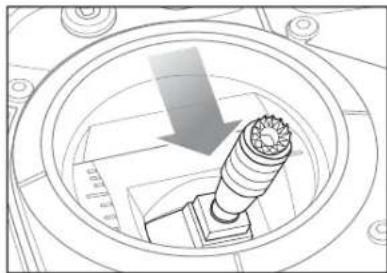
- Lower the throttle.
- Power on the transmitter.
- Center the throttle trim.
- To allow the ESC to arm and to keep rotors from initiating at startup, turn on throttle hold and normal flight mode before connecting the flight battery.
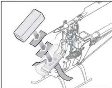
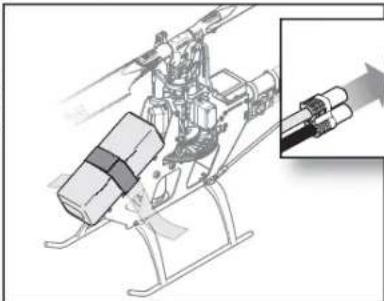
- Attach hook material to the helicopter frame and loop material to the battery.
-
Install the f1ight battery on the helicopter frame. Secure the f1ight battery with a hook and loop strap. Connect the battery cable to the ESC.
-
Do not move the helicopter until the AR636A initializes. The swashplate will center, indicating that the unit is ready. The AR636A will also emit a solid orange Status LED when it is ready.
- The helicopter motor will emit 2 ascending tones, indicating the ESC is armed.
CAUTION: Always disconnect the Li-Po battery from the ESC power lead when not flying to avoid over-discharging the battery. Batteries discharged to a voltage lower than the lowest approved voltage may become damaged, resulting in loss of performance and potential fire when batteries are charged.
Transmitter and Receiver Binding
Binding is the process of programming the receiver to recognize the GUID (Globally Unique Identifiers) code of a single specific transmitter. You need to 'bind' your
chosen Spektrum™ DSM2/DSMX technology equipped aircraft transmitter to the receiver for proper operation.
Binding Procedure
- Program your transmitter using the Transmitter Setup found in this manual.
- Insert the bind plug in the BND/DAT port on the receiver.
- Connect the flight battery to the ESC. The orange LED on the AR636 will begin flashing rapidly to indicate bind mode.
- Move the throttle stick to the low throttle position in normal mode.
- Follow the procedures of your specific transmitter to enter Bind Mode. The system will connect within a few seconds. Once connected, the orange LED will turn off and the AR636A will start the initialization process.
- When the initialization process is complete, the Status LED light will come on solid orange.
- Disconnect the flight battery and remove the bind plug from the AR636A. Store the bind plug in a convenient place.

WARNING: You must move the throttle to the LOW/OFF position during the binding. Failure to do so may cause the rotor blades to spin and the rotor to lift during the AR636A initialization, which could result in damage to property and injury.
NOTICE: Remove the bind plug to prevent the system from entering bind mode the next time the power is turned on.

CAUTION: When using a Futaba® transmitter with a Spektrum™ DSM2® module, you must reverse the throttle channel
If you encounter problems, obey binding instructions and refer to transmitter troubleshooting guide for other instructions. If needed, contact the appropriate Horizon Product Support office.
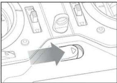
Throttle Hold
Throttle hold only turns off the motor on an electric helicopter. You maintain pitch and direction control.
The blades will spin if throttle hold is OFF. For safety, turn throttle hold ON any time you need to touch the helicopter or check the direction controls.
Throttle hold is also used to turn off the motor if the helicopter is out of control, in danger of crashing, or both.
Control Tests

CAUTION: You must complete the Tail Rotor and Cyclic tests prior to every flight. Failure to complete the tests and ensuring the sensor corrects in the proper direction can cause the helicopter to crash, resulting in property damage and injury.
Tail Rotor
- Power on the transmitter.
- Turn TH HOLD ON and put transmitter in normal mode.
- Connect the flight battery to the ESC.
NOTICE: Do not allow the helicopter to move until the Status LED is solid orange. The AR636A will not operate correctly if the helicopter moves before the Status LED is solid orange.
Cyclic
When using a flbarless flight controller, you are controlling rotational rates while the AR636A controls the servos. You are not directly controlling the servos with the transmitter. It is normal for the swashplate to slowly move back to its original position after a stick input and for the servos to not move at the same speed as your control sticks.
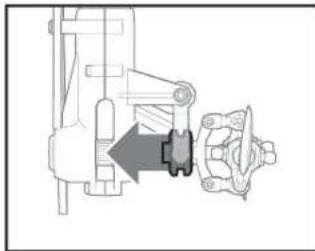
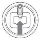
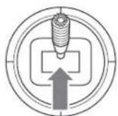
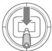
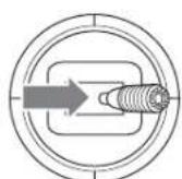
- Move the rudder stick to the right. The pitch slider on the tail shaft should move toward the tail case. If the pitch slider moves in the opposite direction, ensure the rudder channel reverse setting within the transmitter is set to normal.
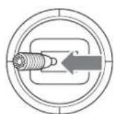
- Release the rudder control. Manually turn the helicopter nose to the left. The flight controller should compensate by moving the tail slider towards the tail case.
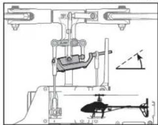
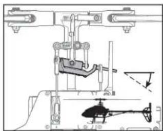
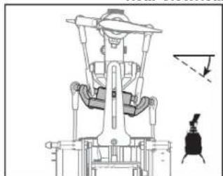
- Tilt the helicopter forward. The swashplate must tilt backward.
- Tilt the helicopter backward. The swashplate must tilt forward.
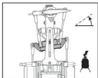
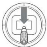
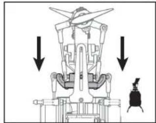
- Roll the helicopter left. The swashplate must roll right.
- Roll the helicopter right. The swashplate must roll left.
Cyclic and Collective Control Test
Ensure the throttle hold is ON when performing the direction control tests. Test the controls prior to each flight to ensure the servos, linkages and parts operate correctly. If the controls do not react as shown in the illustrations below,
Elevator
Left Side View Left Side
Aileron
Collective Pitch
Motor Test
Place the helicopter outdoors on a clean, fl at and level surface (concrete or asphalt) free of obstructions. Always stay clear of moving rotor blades.
- Before you continue, confirm that TH HOLD is ON. The motor will emit 5 ascending tones after the helicopter's ESC has armed properly.

WARNING: The motor will spin when the throttle is increased while TH HOLD is OFF
confi rm the transmitter is programmed correctly before continuing on to the Motor test.
W
Rear ViewRear View
Rear ViewRear View

WARNING: Stay at least 30 feet (10 meters) away from the helicopter when the motor is running. Do not attempt to fly the helicopter at this time.
- Ensure the throttle is lowered completely. Confirrm the transmitter is still set to normal flighth mode. Turn throttle hold OFF to enable throttle control. Slowly increase the throttle until the blades begin to spin. The main blades spin clockwise when viewing the helicopter from the top. The tail rotor blades spin counterclockwise when viewing the helicopter from the right-hand side.
Pre-Flight Checklist
Check all screws and ensure that they are tight.
Check belt tension and ensure that it is not too tight or too loose
Check main and tail blades to ensure they are not damaged
- Check all links and make sure they move freely but do not pop off easily
Check that flight battery and transmitter battery are fully charged
Check all wires to ensure that they are not cut, pinched, or chaffed and are properly secured
Flying the Blade 360 CFX 3S
Consult local laws and ordinances before choosing a location to fly your aircraft.
Select a large, open area away from people and objects. Your first flight should be outdoors in low-wind conditions. Always stay at least 30 feet (10 meters) away from the helicopter when it is flying.
The Blade 360 CFX 3S is intended to be fl own outdoors by experienced pilots
Takeoff
Deliberately increase throttle and establish a hover at least 24" (0.6 meter) high, outside of ground effect.

CAUTION: Making large inputs to the roll or pitch controls while the helicopter is on the ground may result in a crash.
Flying
The helicopter lifts off the ground when the rotor head reaches a suitable speed. Establish a low-level hover to verify proper operation of your helicopter.
First flights should be performed in normal mode and low cyclic and rudder dual rates until you are familiar with the fl ying manner of the Blade 360 CFX 3S.
Gyro Gain Adjustment
- If the tail wags or oscillates, lower the gain on the gyro.
On your transmitter's gyro menu, decrease the gyro gain values a small amount at a time until the helicopter is stable within a particular flight mode.
Tail Belt Tension
Check all wire connections
Check gears and make sure no teeth are missing
Do a complete control test
Verify the AR636A sensor is correcting in the proper directions
Check that servos are functioning properly
Check to make sure flight battery is properly secured
Check to make sure AR636A is properly secured

CAUTION: Always fly the helicopter with your back to the sun and the wind to prevent loss of flight control.
Landing
Establish a low level hover. Deliberately lower the throttle until the helicopter lands.
When the helicopter is in stunt mode:
The rotor head speed is constant.
- The main rotor will increase negative pitch as the throttle/collective stick is moved from the middle stick position to the low stick position. Negative pitch allows the helicopter to fly upside down and perform aerobatics.
Change between stunt and idle up modes in a hover with the throttle near the hovering stick position.

WARNING: Do not use wooden main blades with the Blade 360 CFX 3S or injury and/or property damage could occur. Only use Blade 360 CFX
3S replacement carbon fiber main blades.
- If the tail is drifting while hovering, increase the gain on the gyro.
On your transmitter, increase the gyro gain values a small amount at a time until the tail starts to wag/oscillate. Afterwards, reduce the gain until the tail stops wagging/oscillating within a particular flight mode.
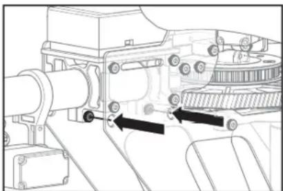
To adjust belt tension:
- Loosen the two horizontal stabilizer screws.
- Loosen the 2 screws at the back of the main frame.
- Slide the boom forward or aft to adjust the belt tension.
- When the belt tension is properly adjusted, tighten the 2 screws at the back of the frame.
- Tighten the horizontal stabilizer screws.
Post-Flight Inspections and Maintenance
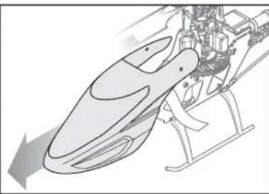
| Ball Links | Make sure the plastic ball link holds the control ball, but is not tight (binding) on the ball. When a link is too loose on the ball, it can separate from the ball during flight and cause a crash. Replace worn ball links before they fail. |
| Cleaning | Make sure the battery is not connected before cleaning. Remove dust and debris with a soft brush or a dry lint free cloth. |
| Bearings | Replace bearings when they become damaged. |
| Wiring | Make sure wiring does not block moving parts. Replace damaged wiring and loose connectors. |
| Fasteners | Make sure there are no loose screws, other fasteners or connectors. Do not over tighten metal screws in plastic parts. Tighten screw so parts are mated together, then turn screw only 1/8th of a turn more. |
| Rotors | Make sure there is no damage to rotor blades and other parts which move at high speed. Damage to these parts includes cracks, burrs, chips or scratches. Replace damaged parts before flying. |
| Flight Controller | Make sure the AR636A is securely attached to the frame. Replace the double-sided tape when necessary. The helicopter will crash if the AR636A separates from the helicopter frame. |
Advanced Settings
The 360 CFX 3S default settings are appropriate for most users. We recommend flying with the default parameters before making any adjustments.

WARNING: To ensure your safety, always disconnect the motor wires from the ESC before performing the following steps. After you have completed the adjustments, reconnect the motor wires to the ESC before attempting to fly the model.
Gain Parameters
- Cyclic P Gain Adjustment (Default 100%)
Higher gain will result in greater stability. Setting the gain too high may result in random twitches if your model has an excessive level of vibration. High frequency oscillations may also occur if the gain is set too high.
Lower gain will result in less stability. Too low of a value may result in a less stable model particularly outdoors in winds.
If you are located at a higher altitude or in a warmer climate, higher gains may be beneficial—the opposite is true for lower altitude or colder climates.
- Cyclic I Gain Adjustment (Default 100%)
Higher gain will result in the model remaining still, but may cause low frequency oscillations if increased too far.
Lower gain will result in the model drifting slowly.
If you are located at a higher altitude or in a warmer climate, higher gains may be beneficial—the opposite is true for lower altitude or colder climates.
- Cyclic D Gain Adjustment (Default 100%)
Higher gain will improve the response rate of your inputs. If the gain is raised too much, high frequency oscillations may occur.
Lower gain will slow down the response to inputs.
- Cyclic Response (Default 100%)
Higher cyclic response will result in a more aggressive cyclic response.
Lower cyclic response will result in a less aggressive cyclic response.
- Tailrotor P Gain Adjustment (Default 100%)
Higher gain will result in greater stability. Setting the gain too high may result in random twitches if your model has an excessive level of vibration. High frequency oscillations may also occur if the gain is set too high.
Lower gain may result in a decrease in stability. Too low of a value may result in a less stable model particularly outdoors in winds.
If you are located at a higher altitude or in a warmer climate, higher gains may be beneficial—the opposite is true for lower altitude or colder climates.
- Tailrotor I Gain Adjustment (Default 100%)
Higher gain results in the tail remaining still. If the gain is raised too far, low speed oscillations may occur.
Lower gain will result in the tail drifting in flight over time.
If you are located at a higher altitude or in a warmer climate, higher gains may be beneficial—the opposite is true for lower altitude or colder climates.
- Tailrotor D Gain Adjustment (Default 100%)
Higher gain will improve the response rate to your inputs. If raised too far, high frequency oscillations may occur.
Lower gain will slow down the response to inputs, but will not have an effect on stability.
Entering Gain Adjustment Mode
DX6G2, DX6e and DX6i Users:
- Lower the throttle stick to the lowest position.
- Power ON the transmitter.
- Install the flight battery on the helicopter frame, securing it with the hook and loop strap.
- Connect the battery connector to the ESC.
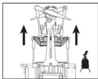
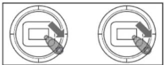
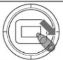
- Before initialization is complete, move and hold both transmitter sticks to the bottom right corner as shown.
- When the servos move, you have entered Gain Adjustment Mode.
- Release the sticks and proceed to Adjusting the Gain Values to make any desired changes.
Adjusting the Gain Values
If you are using a Spektrum™ telemetry-enabled transmitter, the gain adjustments can be viewed on the Flight Log screen. Refer to your transmitter instructions to locate this screen. The gain parameter currently selected will fly ash on the transmitter screen. If you are not using a Spektrum telemetry-enabled transmitter, the parameter and gain values are indicated by the position of the swashplate on the helicopter.
Flight Log Screen
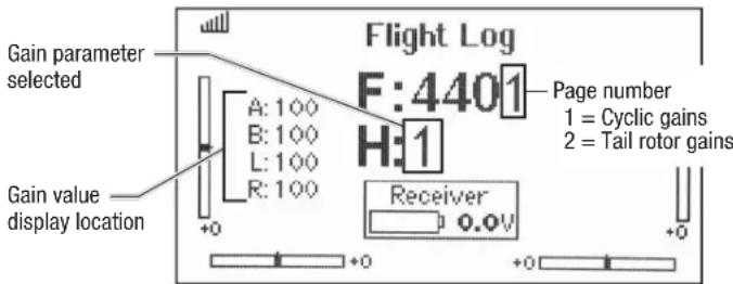
Once you have entered Gain Adjustment Mode, you can move the cyclic stick right and left to select the gain parameter you would like to adjust. Moving the stick right will select the next parameter. Moving the stick left will select the previous parameter.
The selected gain parameter is indicated on the Flight Log screen and by the lean of the swashplate on the roll axis.
| Parameter #Display location Swash Position Page # | ||
| 1 A 100% to the Left 1 | ||
| 2 B 50% to the Left 1 | ||
| 3 L 25% to the Left 1 | ||
| 4 R Swashplate Level 1 | ||
| 5 A 25% to the Right 2 | ||
| 6 B 50% to the Right 2 | ||
| 7 L 100% to the Right | 2 | |
DX7s / DX7 G2 / DX8 / DX8 G2 / DX9 / DX18 / DX20 Users:
- Lower the throttle stick to the lowest position.
- Power ON the transmitter.
- Install the flight battery on the helicopter frame, securing it with the hook and loop strap.
- Connect the battery connector to the ESC.
- Place the helicopter on a flat surface and leave it still until the orange receiver LED glows solid, indicating initialization is complete.
- Move and hold both transmitter sticks to the bottom right corner as shown.
- Press and hold the bind/panic switch until the swash servos move.
- Release the sticks and the bind/panic switch. The model is now in Gain Adjustment Mode.
- Proceed to Adjusting the Gain Values to make any desired changes.
The current gain value for the selected parameter is indicated on the Flight Log screen and by the angle of the swashplate (forward or backward) as shown in the table at the right.
Move the cyclic stick forward or
backward to adjust the gain value. Moving the stick forward will increase the gain value. Moving the stick backward will decrease the gain value.
It is always best to adjust one gain at a time. Make small adjustments (5% or less) and test fly the model to evaluate the adjustments that were made.
If you would like to reset the current gain value to the default value of 100% , move and hold the rudder stick full right for 1 second. The swash will level on the pitch axis, indicating a 100% gain setting.
Saving the Gain Adjustments
DX6, DX6e and DX6i Users:
- Lower the throttle stick to the lowest position and release the sticks.
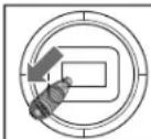
- Move the tail rotor stick to the left and hold until the servos move.
- Release the tail rotor stick to save the gain adjustments.
- Reconnect the main drive motor to the ESC. Your model is now ready for flight.
DX7s / DX7 G2 / DX8 / DX8 G2 / DX9 / DX18 / DX20 Users:
- Lower the throttle stick to the lowest position and release the sticks.
- Press and hold switch I until the swash servos move.
- Release switch I to save the gain adjustments.
- Reconnect the main drive motor to the ESC. Your model is now ready for flight.
Servo Adjustment
Your Blade 360 CFX 3S was setup at the factory and test fl own. The servo adjustment steps are usually only necessary in special circumstances, such as after a crash or if a servo or linkage is replaced.

WARNING: To ensure your safety, always disconnect the motor wires from the ESC before performing the following steps. After you have completed the adjustreconnect the motor wires to the ESC before attempting to fly the model.
Entering Servo Adjustment Mode
DX6G2, DX6e and DX6i Users:
- Lower the throttle stick to the lowest position.
- Power ON the transmitter.
- Install the flight battery on the helicopter frame, securing it with the hook and loop strap.
- Connect the battery connector to the ESC.
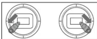
- Before initialization is complete, hold the left stick to the bottom left corner and the right stick to the bottom right corner as shown.
- When the swashplate servos move, you have entered Servo Adjustment Mode.
- Release the sticks and proceed to Adjusting the Servo Neutral Position to make any desired changes.
DX7s/DX7 G2/DX8/DX8 G2/DX9/DX18/DX20 Users:
- Lower the throttle stick to the lowest position.
- Power ON the transmitter.
- Install the flight battery on the helicopter frame, securing it with the hook and loop strap.
- Connect the battery connector to the ESC.
- Place the helicopter on a fl at surface and leave it still until the orange receiver LED glows solid, indicating initialization is complete.
- Hold the left stick to the bottom left corner and the right stick to the bottom right corner as shown.
- Hold the bind/panic switch until the swash servos move.
- Release the sticks and the bind/panic switch. The model is now in Servo Adjustment Mode.
- Proceed to Adjusting the Servo Neutral Position to make any desired changes.
Adjusting the Servo Neutral Position
With the model in Servo Adjustment Mode, the control stick and gyro inputs are disabled and the servos are held in the neutral position. Check the position of the servo arms to see if they are perpendicular to the servos.
- If the arms are perpendicular to the servos, no adjustment is necessary. Exit Servo Adjustment Mode.
- If one or more servo arm is not perpendicular to the servos, continue the servo adjustment process.
While watching the swashplate servos, apply right cyclic and release. One of the servos will jump, indicating which servo is selected. Press right cyclic and release until the servo that needs to be adjusted is selected.
Once the servo you wish to adjust is selected, move the cyclic stick forward or backward to adjust the servo neutral position in the desired direction.
If you would like to reset the current servo to the default neutral position, hold the rudder stick full right for 1 second.
The range of adjustment is limited. If you are unable to adjust the servo arm to be perpendicular to the servo, you must reset the servo to the default neutral position, remove the servo arm and place it back onto the servo as close to perpendicular as possible. You may then adjust the servo neutral position using the forward/ backward cyclic stick.
Swashplate Leveling
Before saving your adjustments and exiting servo adjustment mode, verify the swashplate is level and both main rotor blades are at 0 degrees. If they are not, make linkage adjustments as necessary.
Saving the Servo Adjustments
DX6, DX6e, and DX6i Users:
- Lower the throttle stick to the lowest position and release the sticks.
- Move the tail rotor stick to the left and hold until the servos move.
- Release the tail rotor stick to save the servo adjustments.
-
Reconnect the main drive motor to the ESC. Your model is now ready for flight. DX7s / DX7 G2 / DX8 / DX8 G2 / DX9 / DX18 / DX20 Users:
-
Lower the throttle stick to the lowest position and release the sticks.
- Press and hold switch I until the swash servos move.
- Release switch I to save the servo adjustments.
- Reconnect the main drive motor to the ESC. Your model is now ready for flight. All of the settings are stored internally, so your adjustments will be maintained each time you initialize the model.
Problem Possible Cause Solution
| Helicopter will not bind to the transmitter (during binding) | Low flight battery or transmitter battery voltage | Fully charge or replace the flight battery and/or transmitter batteries |
| AR636A is not in bind mode Make sure the bind plug is connected to the AR636A BND/DAT port | ||
| Transmitter is not in bind mode | Power on the transmitter while holding the Trainer/Bind switch. Hold the Trainer/Bind switch until binding is complete | |
| Transmitter too close to the helicopter during binding process | Power off the transmitter. Move the transmitter further away from the helicopter. Disconnect and reconnect the flight battery to the helicopter and follow binding instructions | |
| Helicopter will not link to the transmitter (after binding) | Helicopter is bound to a different model memory (ModelMatch™ radios only) | Disconnect the flight battery. Select the correct model memory on the transmitter Reconnect the flight battery |
| Flight battery/Transmitter battery charge is too low Replace or recharge batteries | ||
| AR636A will not initialize | The helicopter was moved during initialization Lay the heli-copter on its side during initialization if windy | |
| The transmitter is powered off Power on the transmitter | ||
| Controls are not centered Center elevator, aileron and rudder controls. Make sure the throttle is at idle | ||
| Helicopter will not respond to the throttle but responds to other controls | Throttle not at idle and/or throttle trim is too high Lower the throttle stick and lower the throttle trim | |
| The transmitter is not in normal mode or throttle hold is on | Make sure the transmitter is in normal mode and throttle hold is off | |
| The motor is not connected to the ESC or the motor wires are damaged | Connect the motor wires to the ESC and check motor wires for damage | |
| Flight battery charge is too low Replace or recharge flight battery | ||
| Throttle channel is reversed Reverse the throttle channel on the transmitter | ||
| Helicopter power is lacking | Flight battery has low voltage | Fully charge the flight battery |
| Flight battery is old or damaged | Replace the flight battery | |
| Flight battery cells are unbalanced | Fully charge the flight battery, allowing the charger time to balance the cells | |
| Excessive current is being drawn through the BEC | Check all servos and the helicopter motor for damage | |
| Tail drive belt tension is not correct | See "Checking Tail Drive Belt Tension" in this manual | |
| Helicopter will not lift off | Main rotor head is not spinning in the correct direction | Make sure the main rotor head is spinning clockwise. Refer to the motor control test |
| Transmitter settings are not correct | Check throttle and pitch curve settings and pitch control direction | |
| Flight battery has low voltage | Fully charge the flight battery | |
| Main rotor blades are installed backwards | Install the main rotor blades with the thicker side as the leading edge | |
| The helicopter tail spins out of control | Rudder control and/or sensor direction reversed | Make sure the rudder control and the rudder sensor are operating in the correct direction |
| Tail servo is damaged | Check the rudder servo for damage and replace if necessary | |
| Inadequate control arm throw | Check the rudder control arm for adequate travel and adjust if necessary | |
| Tail belt is too loose | Make sure the tail drive belt tension is adjusted correctly | |
| The helicopter wobbles in fl light | Cyclic gain is too high | Please review the Advanced Settings - Gain Adjustments section |
| Headspeed is too low | Increase the helicopter's head speed via your transmitter settings and/or using a freshly charged fl light pack | |
| Dampers are worn | Replace the main rotor head dampers | |
Limited Warranty
What this Warranty Covers
Horizon Hobby, LLC, (Horizon) warrants to the original purchaser that the product purchased (the "Product") will be free from defects in materials and workmanship at the date of purchase.
What is Not Covered
This warranty is not transferable and does not cover (i) cosmetic damage, (ii) damage due to acts of God, accident, misuse, abuse, negligence, commercial use, or due to improper use, installation, operation or maintenance, (iii) modification of or to any part of the Product, (iv) attempted service by anyone other than a Horizon Hobby authorized service center, (v) Product not purchased from an authorized Horizon dealer, (vi) Product not compliant with applicable technical regulations, or (vii) use that violates any applicable laws, rules, or regulations.
OTHER THAN THE EXPRESS WARRANTY ABOVE, HORIZON MAKES NO OTHER WARRANTY OR REPRESENTATION, AND HEREBY DISCLAIMS ANY AND ALL IMPLIED WARRANTYES, INCLUDING, WITHOUT LIMITATION, THE IMPLIED WARRANTYES OF NON-INFRINGEMENT, MERCHANTABILITY AND FITNESS FOR A PARTICULAR PURPOSE. THE PURCHASER ACKNOWLEDGES THAT THEY ALONE HAVE DETERMINED THAT THE PRODUCT WILL SUITABLY MEET THE REQUIREMENTS OF THE PURCHASER'S INTENDED USE.
Purchaser's Remedy
Horizon's sole obligation and purchaser's sole and exclusive remedy shall be that Horizon will, at its option, either (i) service, or (ii) replace, any Product determined by Horizon to be defective. Horizon reserves the right to inspect any and all Product(s) involved in a warranty claim. Service or replacement decisions are at the sole discretion of Horizon. Proof of purchase is required for all warranty claims. SERVICE OR REPLACEMENT AS PROVIDED UNDER THIS WARRANTY IS THE PURCHASER'S SOLE AND EXCLUSIVE REMEDY.
Limitation of Liability
HORIZON SHALL NOT BE LIABLE FOR SPECIAL, INDIRECT, INCIDENTAL OR CONSEQUENTIAL DAMAGES, LOSS OF PROFITS OR PRODUCTION OR COMMERCIAL LOSS IN ANY WAY, REGARDLESS OF WHETHER SUCH CLAIM IS BASED IN CONTRACT, WARRANTY, TORT, NEGLIGENCE, STRICT LIABILITY OR ANY OTHER THEORY OF LIABILITY, EVEN IF HORIZON HAS BEEN ADVISED OF THE POSSIBILITY OF SUCH DAMAGES. Further, in no event shall the liability of Horizon exceed the individual price of the Product on which liability is asserted. As Horizon has no control over use, setup, final assembly, modification or misuse, no liability shall be assumed nor accepted for any resulting damage or injury. By the act of use, setup or assembly, the user accepts all resulting liability. If you as the purchaser or user are not prepared to accept the liability associated with the use of the Product, purchaser is advised to return the Product immediately in new and unused condition to the place of purchase.
Law
These terms are governed by Illinois law (without regard to conflict of law principals). This warranty gives you specific legal rights, and you may also have other rights which vary from state to state. Horizon reserves the right to change or modify this warranty at any time without notice.
WARRANTY SERVICES
Questions, Assistance, and Services
Your local hobby store and/or place of purchase cannot provide warranty support or service. Once assembly, setup or use of the Product has been started, you must contact your local distributor or Horizon directly. This will enable Horizon to better answer your questions and service you in the event that you may need any assistance. For questions or assistance, please visit our website at www.horizonhobby.com, submit a Product Support Inquiry, or call the toll free telephone number referenced in the Warranty and Service Contact Information section to speak with a Product Support representative.
Inspection or Services
If this Product needs to be inspected or serviced and is compliant in the country you live and use the Product in, please use the Horizon Online Service Request submission process found on our website or call Horizon to obtain a Return Merchandise Authorization (RMA) number. Pack the Product securely using a shipping carton. Please note that original boxes may be included, but are not designed to withstand the rigors of shipping without additional protection. Ship via a carrier that provides tracking and insurance for lost or damaged parcels, as Horizon is not responsible for merchandise until it arrives and is accepted at our facility. An Online Service Request is available at http://www.horizonhobby.com/content/service-center_render-service-center. If you do not have internet access, please contact Horizon Product Support to obtain a RMA number along with instructions for submitting your product for service. When calling Horizon, you will be asked to provide your complete name, street address, email address and phone number where you can be reached during business hours. When sending product into Horizon, please include your RMA number, a list of the included items, and a brief summary of the problem. A copy of your original sales receipt must be included for warranty consideration. Be sure your name, address, and RMA number are clearly written on the outside of the shipping carton.
NOTICE: Do not ship LiPo batteries to Horizon. If you have any issue with a LiPo battery, please contact the appropriate Horizon Product Support office.
Warranty Requirements
For Warranty consideration, you must include your original sales receipt verifying the proof-of-purchase date. Provided warranty conditions have been met, your Product will be serviced or replaced free of charge. Service or replacement decisions are at the sole discretion of Horizon.
Non-Warranty Service
Should your service not be covered by warranty, service will be completed and payment will be required without notifi cation or estimate of the expense unless the expense exceeds 50% of the retail purchase cost. By submitting the item for service you are agreeing to payment of the service without notifi cation. Service estimates are available upon request. You must include this request with your item submitted for service. Non-warranty service estimates will be billed a minimum of 12 hour of labor. In addition you will be billed for return freight. Horizon accepts money orders and cashier's checks, as well as Visa, MasterCard, American Express, and Discover cards. By submitting any item to Horizon for service, you are agreeing to Horizon's Terms and Conditions found on our website http:// www.horizonhobby.com/content/service-center_render-service-center.
ATTENTION: Horizon service is limited to Product compliant in the country of use and ownership. If received, a non-compliant Product will not be serviced. Further, the sender will be responsible for arranging return shipment of the un-serviced Product, through a carrier of the sender's choice and at the sender's expense. Horizon will hold non-compliant Product for a period of 60 days from notification, after which it will be discarded. 10/15
Warranty and Service Contact Information
| Country of Purchase | Horizon Hobby Contact Information Address | ||
| United States of America | Horizon Service Center (Repairs and Repair Requests) service center.horizonhobby.com/RequestForm/ | 4105 Fieldstone RdChampaign, Illinois, 61822 USA | |
| Horizon Product Support (Product Technical Assistance) | productsupport@horizonhobby.com | ||
| 877-504-0233 | |||
| Sales | websales@horizonhobby.com | ||
| 800-338-4639 | |||
| European Union | Horizon Technischer Service service@horizonhobby.eu | Hanskampring 9D 22885 Barsbüttel, Germany | |
| Sales: Horizon Hobby GmbH +49 (0) 4121 2655 100 | |||
FCC Information
FCC ID: BRWDASRX15
This equipment has been tested and found to comply with the limits for Part 15 of the FCC rules. These limits are designed to provide reasonable protection against harmful interference in a residential installation. This equipment generates uses and can radiate radio frequency energy and, if not installed and used in accordance with the instructions, may cause harmful interference to radio communications.
However, there is no guarantee that interference will not occur in a particular installation. If this equipment does cause harmful interference to radio or television reception, which can be determined by turning the equipment off and on, the user is encouraged to try to correct the interference by one or more of the following measures:
- Reorient or relocate the receiving antenna.
- Increase the separation between the equipment and receiver.
- Connect the equipment to an outlet on a circuit different from that to which the receiver is connected.
This device complies with part 15 of the FCC rules. Operation is subject to the following two conditions: (1) This device may not cause harmful interference, and (2) this device must accept any interference received, including interference that may cause undesired operation.
NOTICE: Modifi cations to this product will void the user's authority to operate this equipment.
IC Information
IC:6157A-AMRX15
This device complies with Industry Canada licence-exempt RSS standard(s). Operation is subject to the following two conditions: (1) this device may not cause interference, and (2) this device must accept any interference, including interference that may cause undesired operation of the device."
Compliance Information for the European Union


EU Compliance Statement:
Horizn Hb, t h t t t t t t t t t t
A copy of the EU Declaration of Conformity is available online at: http://www.horizonhobby.com/content/support-render-compliance.
Instructions for disposal of WEEE by users in the European Union

This product must not be disposed of with other waste. Instead, it is the user's responsibility to dispose of their waste equipment by handing it over to a designated collections point for the recycling of waste electrical and electronic equipment. The separate collection and recycling of your waste equipment at the time of disposal will help to conserve natural resources and make sure that it is recycled in a manner that protects human health and the environment. For more information about where you can drop off your waste equipment for recycling, please contact your local city office, your household waste disposal service or where you purchased the product.

HINWEIS
DX6G2, DX6e, DX7G2, DX8G2, DX9, DX18, DX20
Systemeinstellung
Throttle Hold [Autorotation]
| GYRO | |||
| RATE | SW-F.MODE | ||
| 0 | 60% | NORM | 0 |
| 1 | 50% | STUNT | 1 |
| Pitch Curve | |||||
| Switch Pos (F Mode) | Pos 1 | Pos 2 | Pos 3 | Pos 4 | Pos 5 |
| NORM | 25 | 37 | 50 | 75 | 100 |
| STUNT 0 25 50 | 75 | 100 | |||
| HOLD | 25 | 37 | 50 | 75 | 100 |
DX7s, DX8
DX6G2, DX6e, DX7G2, DX8G2, DX9, DX18, DX20
| TYPE de modele | |
| HELI | |
| Type de plateau cyclique | |
| Normal | |
| Mode de vol | |
| Inter. 1 | Inter. B |
| Inter. 2 | Déactivé |
| Auto-rotation | Inter. H |
| 0 1 | |
LISTES DES FONCTIONS
| Course des servos | |||||
| Voie | Course | Inversion | Voie | Course | Inversion |
| Gaz | 100/100 | Normal | PIT | 100/100 | Normal |
| Allerons | 100/100 | Normal | AX2* | 100/100 | Normal |
| Profondeur | 100/100 | Normal | AX3* | 100/100 | Normal |
| Dérive | 100/100 | Normal | AX4* | 100/100 | Normal |
| Train | 100/100 | Normal | |||
http://www.horizonhobby.com/content/support-render-compliance.
| GYRO | |||
| RATE | SW-F.MODE | ||
| 0 | 60% | NORM | 0 |
| 1 | 50% | STUNT | 1 |
Curva motore
| Switch Pos (F Mode) | Pos 1 | Pos 2 | Pos 3 | Pos 4 | Pos 5 | |
| NORM | 25 | 37 | 50 | 75 | 100 | |
| STUNT 0 25 | 50 | 75 | 100 | |||
| HOLD | 25 | 37 | 50 | 75 | 100 |
DX7s, DX8
SYSTEM SETUP
DX6G2, DX6e, DX7G2, DX8G2, DX9, DX18, DX20
SYSTEMSETUP
| Normal | 85.0% |
| Stunt 1 | 80.0% |
| Stunt 2 | 75.0% |
| Hold | 85.0% |
| Channel Gear | |
| Switch | Flight Mode |
![Blade 360 CFX 3S - Throttle Hold [Autorotation] - 1](/content/2026/02/421126/images/6d52fafb771643ea2e871a17856a5b8be86a1be3e407f6eb9aede4b834c484b5.jpg)
![Blade 360 CFX 3S - Throttle Hold [Autorotation] - 2](/content/2026/02/421126/images/5c17ac2e8fc7aead9f87b60576ec0380d75b81a9fb8d16c3cd156d064d864d46.jpg)
![Blade 360 CFX 3S - Throttle Hold [Autorotation] - 3](/content/2026/02/421126/images/fb88d11087ced6cdaed5caf08ff5a2af0e127ece7c166cf917e883381e510c90.jpg)
![Blade 360 CFX 3S - Throttle Hold [Autorotation] - 4](/content/2026/02/421126/images/8b06877ba6470d63252b70598ae2383dccc3e928fc2462fd6b15e8b207f7cbe3.jpg)
![Blade 360 CFX 3S - Throttle Hold [Autorotation] - 5](/content/2026/02/421126/images/59cb89ff5dc0fe0172fce9454e31f6e1d4e448b7051accaf74af4f87fe381a40.jpg)
![Blade 360 CFX 3S - Throttle Hold [Autorotation] - 6](/content/2026/02/421126/images/f5204aa431f6fe220598b0ab80a822b3ea505389e08d6994697229c9b0ed4ca9.jpg)
Utenti DX7s, DX7 (G2), DX8, DX8 (G2), DX9, DX18 e DX20:
Utenti DX7s, DX7 (G2), DX8, DX8 (G2), DX9, DX18 e DX20:
Upsilon DX7s, DX7 (G2), DX8, DX8 (G2), DX9, DX18 e DX20:
©2017 Horizon Hobby, LLC.
Blade, DSM, DSM2, DSMX, AS3X, ModelMatch, Spektrum AirWare, EC3, BNF, and the BNF logo are trademarks or registered trademarks of Horizon Hobby, LLC.
The Spektrum trademark is used with permission of Bachmann Industries, Inc. Futaba is a registered trademark of Futaba Denshi Kogyo Kabushiki Kaisha Corporation of Japan. All other trademarks, service marks and logos are property of their respective owners.
Patents pending
Created 03/17 55137 BLH5050