Baby Kangoo RB202 - Baby monitors Rimax - Free user manual and instructions
Find the device manual for free Baby Kangoo RB202 Rimax in PDF.
Frequently Asked Questions - Baby Kangoo RB202 Rimax
User questions about Baby Kangoo RB202 Rimax
0 question about this device. Answer the ones you know or ask your own.
Ask a new question about this device
Download the instructions for your Baby monitors in PDF format for free! Find your manual Baby Kangoo RB202 - Rimax and take your electronic device back in hand. On this page are published all the documents necessary for the use of your device. Baby Kangoo RB202 by Rimax.
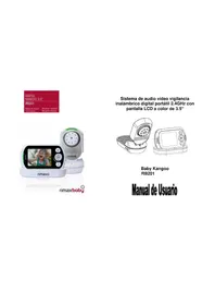
USER MANUAL Baby Kangoo RB202 Rimax
Alternatively, you can use the following method to select the temperature in ^ C and ^ F .
- Digital Wireless Technology Provides Excellent Image Quality and Clarity
- Interference Free, secure and private signal
- Up to 450ft Wireless Transmission Range*
- Listen in with Exceptional Sound Clarity
- Two-way communication
- temperature indicator on the screen
- Safety Warning Feature Notifies You When out of Range
- System expandable up to 4 Cameras**
- Maximum open space transmission range. The actual range is dependent upon building materials and other obstructions in path of wireless signal.
** Additional Cameras sold separately.
Receiver Features:
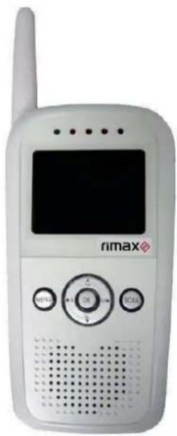
- 2.4" Color LCD Monitor/Receiver with Superior Image Quality
Video/Audio Output for Viewing on TV/Monitor or Recording on VCR/DVD Recorder - Rechargeable Lithium Polymer Battery for True Portability
- Convenient Receiver Cradle and belt clip included
Audio Level indicator and Alarm
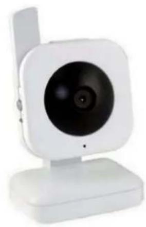
Camera Features:
Night Vision allows for low light viewing up to 15 Feet / 4.5 meters***
Built-in Microphone
- Camera can be battery operated for true portable wireless operation
***IR illumination range of 15ft. / 4.5 m under ideal conditions. Objects at or beyond this range may be partially or completely obscured, depending on the camera application.
The Digital Wireless signal transmission type used in this digital unit is also known as FHSS - Frequency Hopping Spread Spectrum. This type of signal is highly resistant to deliberate jamming as it generates a channel hopping sequence using an algorithm generated by the receiver system.
Getting Started
The System comes with the following components:
1 x WIRELESS RECEIVER 1 x RECEIVER CRADLE 1 x WIRELESS CAMERA(S)*
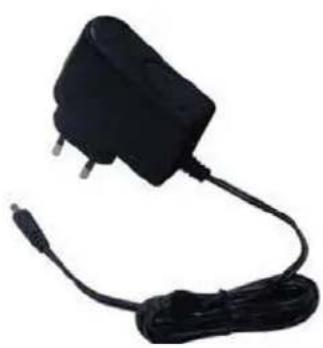
1x POWER ADAPTOR (FOR RECEIVER)
-
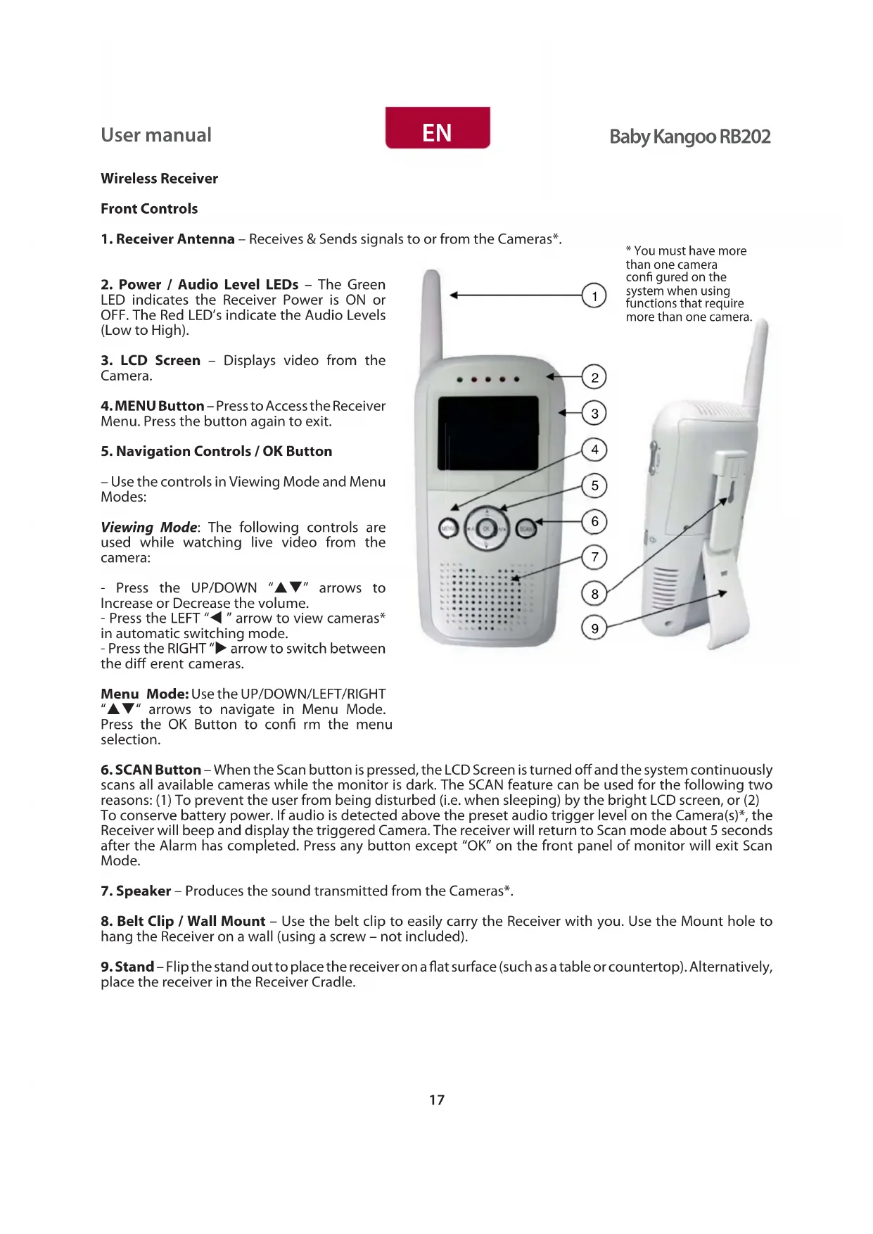
Receiver Antenna - Receives & Sends signals to or from the Cameras*.
-
Power / Audio Level LEDs - The Green LED indicates the Receiver Power is ON or OFF. The Red LED's indicate the Audio Levels (Low to High).
- LCD Screen - Displays video from the Camera.
- MENU Button - Press to Access the Receiver Menu. Press the button again to exit.
5. Navigation Controls / OK Button
- Use the controls in Viewing Mode and Menu Modes:
Viewing Mode: The following controls are used while watching live video from the camera:
- Press the UP/DOWN "▲▼" arrows to Increase or Decrease the volume.
- Press the LEFT "▲" arrow to view cameras* in automatic switching mode.
- Press the RIGHT arrow to switch between the different cameras.
Menu Mode: Use the UP/DOWN/LEFT/RIGHT "▲▼" arrows to navigate in Menu Mode. Press the OK Button to confirm the menu selection.
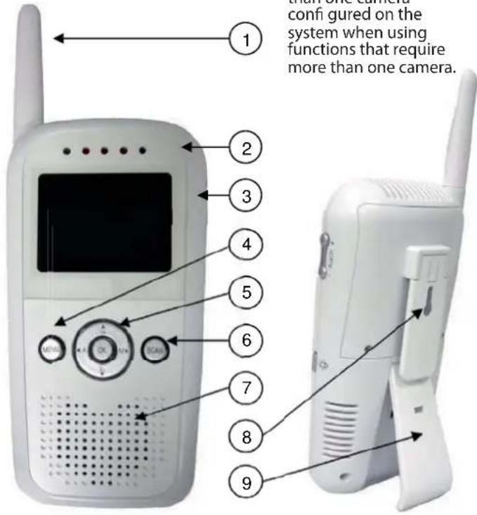
- SCAN Button - When the Scan button is pressed, the LCD Screen is turned off and the system continuously scans all available cameras while the monitor is dark. The SCAN feature can be used for the following two reasons: (1) To prevent the user from being disturbed (i.e. when sleeping) by the bright LCD screen, or (2) To conserve battery power. If audio is detected above the preset audio trigger level on the Camera(s)*, the Receiver will beep and display the triggered Camera. The receiver will return to Scan mode about 5 seconds after the Alarm has completed. Press any button except "OK" on the front panel of monitor will exit Scan Mode.
- Speaker - Produces the sound transmitted from the Cameras*.
- Belt Clip / Wall Mount - Use the belt clip to easily carry the Receiver with you. Use the Mount hole to hang the Receiver on a wall (using a screw - not included).
- Stand - Flip the stand out to place the receiver on a flat surface (such as a table or countertop). Alternatively, place the receiver in the Receiver Cradle.
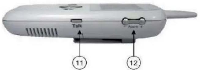
Side Controls
- Night Light Button - Press to remotely turn Night Light ON or OFF (for the camera currently being displayed on the LCD Screen).
- A Alarm +/-Button - Press to increase or decrease the volume of the audio alarm.
- Power Button - Press to turn the Receiver ON or OFF.
- A/V Out Port (Optional Use) - Connect the included A/V Cable to view video from the receiver on a TV or Monitor, or record to a DVD Recorder or VCR. Alternatively, use the A/V Out port on the Receiver Cradle.
NOTE: Using this feature will turn off the LCD screen. The LCD screen will turn back on when the A/V Cable is disconnected.
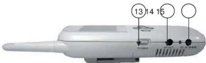
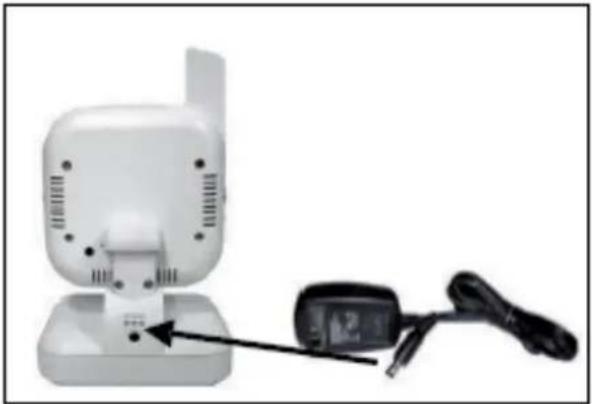
- DC 5V Power Input - Connect the included DC 5V Power Adaptor to power the receiver and/or charge the Receiver battery (when the receiver is not in the Cradle).
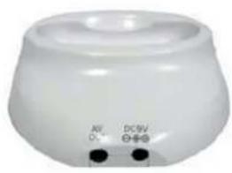
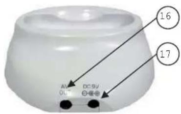
Receiver Cradle Inputs
- A/V Out Port - Connect the included A/V Cable to view the receiver picture (when docked) on a TV or Monitor, or record to a DVD Recorder or VCR. (NOTE: The A/V output function will not work if there is no power cable connected to the cradle.
Only one A/V out port should be used at a time).
- DC 9V Power Input - Connect the DC 5V Power Adaptor (included) to the Receiver Cradle to power the receiver and/or charge the Receiver (when docked).
NOTE: When the Receiver is docked, and the A/V Cable is connected (power cable as needs to be connected), the LCD Screen on the receiver will be blacked out. The LCD screen will turn back on when the A/V Cable is disconnected.
Wireless Receiver Installation
Determine if you will be using the Receiver Cradle, or connecting the cables directly to the receiver before installation:
- Place the Receiver Cradle or Receiver in a place that will have clear reception with your camera(s).
- Plug the AC adaptor power output cable into the 5V POWER input of the Cradle or Receiver. Plug the power plug into a wall outlet or surge protector.
- Leave the receiver to charge for 6 hours prior to first time use so the built-in rechargeable receiver battery is fully charged. DO NOT remove the power cable from the receiver / from the cradle during initial charging process. After initial charge, charge as required.
- If you wish to view the Receiver images on a larger screen, connect the included AV Cable to the Cradle or Receiver, and connect the other end of the Cable to the Video IN (Yellow) and Audio IN (White) ports on the TV, VCR or other viewing/recording device.
NOTE: the purpose of the AV output is for convenience only. When using with large screen TV/ Monitor, the picture might be grainy as the camera limits video resolution to QVGA (320x240 pixels). This is not a product defect. For best performance use with TV/Monitor PIP (Picture in Picture) function.
Check your TV/Monitor product manual to see if this feature is available on your TV/Monitor. This allows you to view TV or other video source and see video from the camera in a small window on the same screen.
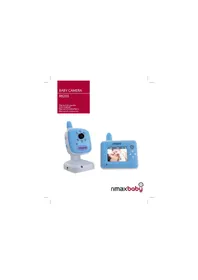
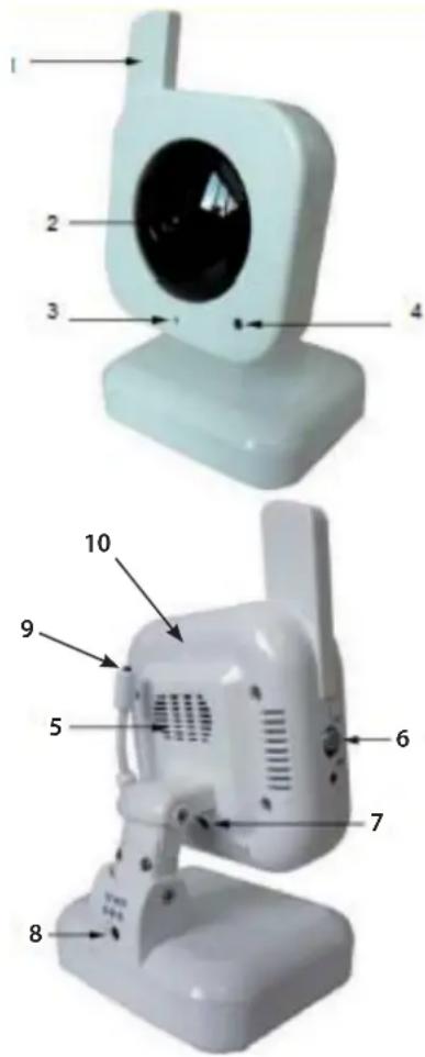
Camera
- Camera Antenna - Receives & Sends signals to or from the Receiver.
- Lens / Cover LED IR - Infrared LEDs provide viewing in no/low light conditions.
- Microphone - Receives sounds for the area near the camera, and transmits sound from the Camera to the Receiver.
- Light sensor - Detects the light level in the room and connect the infrared night vision automatically and connects the nightlight.
- Speaker: Relays the sound emitted from the monitor.
- ON/OFF: Turns the Camera ON or OFF.
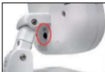
- PAIR button (Pair) - The pairing button is located on the back of the camera, behind the supporting table.
8.5V DC Power - Connect the DC 5V Power Adaptor to the Camera. - Temperature sensor
10. Night Light
NOTE: The Camera can also be powered using 4 AA Batteries (not included) installed in the base. If the Camera is plugged in with the AC Adaptor, the batteries will not be used. The batteries are intended for short term, portable Camera use.
Camera Installation
Before you install the camera, carefully plan where and how it will be positioned, and where you will route the cable that connects the camera to the power adaptor.
Before starting permanent installation, verify its performance by observing the image on the receiver when camera is positioned in the same location/position where it will be permanently installed and the receiver is placed in the location where it will be used most of the time.
InstallationWarnings:
Aim the Camera(s) to best optimize the viewing area: Select a location for the camera that provides a clear view of the area you want to monitor, which is free from dust, and is not in line-of-sight to a strong light source or direct sunlight.
Avoid installing the cameras where there are thick walls, or obstructions between the Cameras and the Receiver.
Night Vision
This camera has built-in IR LEDs, which provides the camera with the ability to view images in no/low light conditions. It is important to use the provided power adaptor (and not the Batteries) when using the camera for prolonged periods in low light conditions, as the built-in IR LEDs will drain the battery more quickly than regular daytime use.
Installing the Camera:
- Carefully unpack the Camera.
- Mount the camera to the wall:
Mark the position of the screw holes on the wall. Drill holes and insert 2 screws.
Firmly attach the camera to the wall by placing the stand over the installed screws and pushing the base downwards to secure.
NOTE:
The camera can also be placed on a flat surface, such as a Table or Shelf, and no mounting hardware is required.
- Adjust the Viewing angle of the Camera.
NOTE:
You can install additional cameras (maximum of 4 cameras). When adding cameras that were not included in the original box; you will need to pair up the cameras with the receiver. Refer to the camera pairing section of this manual.
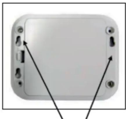
Position the Base holes over the screws. Slide the base down to lock the base in place.
Connecting Camera Power
The Camera can be powered either by using the provided Power Adaptor, or using Batteries (requires 4 x 'AA' type batteries, not included).
NOTE: Wireless cameras require a power source (either an electrical outlet or battery power) to operate. If you plan to permanently mount the camera in a location, it is recommended to use the included Camera Power adaptor to prevent interruptions in the image, as using battery power is intended as a temporary power solution.
POWER ADAPTOR:
Connect the Power Adaptor to the Camera. Make sure the power adaptor is placed into a grounded outlet or surge bar to protect the camera from power fluctuations.
Power Adaptor: Connect the Power Adaptor to the 5V Input on the back of the camera.
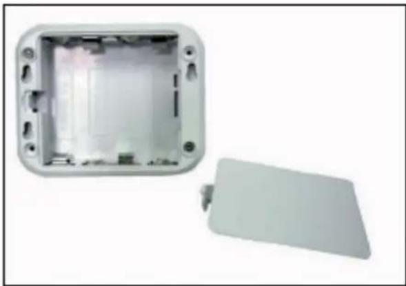
BATTERY PACK:
- Remove the Battery Cover off the base of the Camera.
2.Insert 4× AA Batteries (not included) into the Battery Pack. Make sure to correctly line up the Positive (+) and Negative (-) terminals of the batteries.
Place the Battery Pack cover back on.
NOTE: If the Camera is plugged in with the AC Adaptor, the batteries will not be used. The batteries are intended for short term, portable Camera use only.
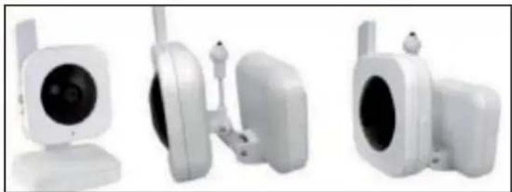
Camera Positioning
The Camera can be placed on a fl at surface, or wall mounted. The versatile stand allows for several different mounting options.
Viewing Mode
1. SIGNAL INDICATOR

The signal indicator shows the strength of the signal being received from the camera. The number of bars in the Signal Indicator shows the strength of the signal - One or No Bars indicates the signal is poor, and 4 bars indicate a very strong signal.
Signal Indicators:

Low Signal Perfect
- CHANNEL INDICATOR - CH1: Displays the current channel number. Press the Right "▶" Button on the Receiver to switch between available cameras.
NOTE: To automatically switch between channels, press the Left "▶" Button (AUTO).
Low Signal / No SignalWarnings
When the Camera is positioned too far from the Receiver, warning messages will be displayed:

LOW SIGNAL: The "Low Signal" signal appears when the receiver has One or Two bars. You will still get an image, however updating may be less frequent.
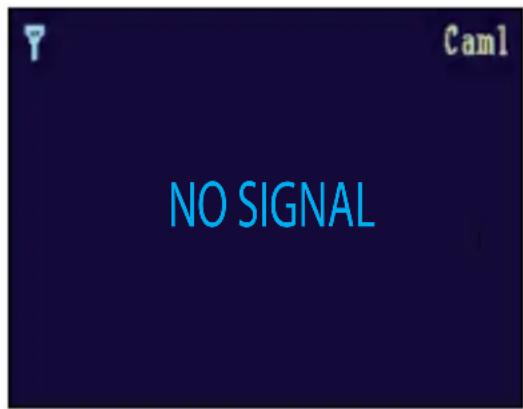
NO SIGNAL: The "No Signal" message means the receiver cannot access the camera. Please reposition the camera, or check the Camera power.
Adjusting the Receiver Volume
The Receiver Volume can be adjusted using the UP andDOWN "▲▼" arrow buttons when viewing a camera.

Press the DOWN "▼" Arrow to decrease the Volume, and press the UP "▲" Arrow to increase the volume. When the volume is set to one bar (lowest setting), the volume is muted.
The Volume Adjustment icon will be displayed during Volume changes, and will disappear after 10 seconds of inactivity.
Accessing Menu System
Press the MENU Button on the Receiver to enter MENU System. Use the "▼▲▶" Buttons to navigate UP, Down, Left or Right in the menu, and press the OK Button to confirm a setting.
Main Menu
The Main Menu contains 6 submenus:

Zoom In/Out: Use this feature to select the image size.
PAIRING (Emparejamento): Use the menu to add a camera (s) to the receiver.
Camera Vol: Use this menu to select the alarm volume.
Brightness: Use this menu to select the brightness of the screen.
VOX setting: Use this menu to adjust the sensitivity of the VOX.
Temp setting: Use this menu to set the temperature alarm or select the "oC" or "oF".
Zoom Menu

Press the Menu button and enter the mode Zoom In / Out, you can navigate with the buttons to zoom in and zoom out.
Camera Pairing

The System comes with camera(s) that have already been paired. These cameras will communicate with the receiver once powered on.
The Pairing Function assigns each Camera to a different channel on the Wireless Receiver (up to 4 Cameras), and is necessary for confi guring additional cameras.
Select a channel by pressing the UP and DOWN "▲▼" arrows. Press the OK Button on the receiver to accept.
NOTE: It is highly recommended to pair the Cameras to the Receiver before permanently mounting the Cameras.
Vol Camera Menu

Use the browser to select the volume of the chamber. Use the LEFT "▲" and RIGHT "▶" to raise or lower the volume of the audio alert.
User manual

Baby Kangoo RB202

Use the browser to select the brightness of the image. Use UP "▲" DOWN "▼" to go from darker to lighter. Press the OK button to accept the changes.
VOX menu

The menu lets you select VOX sensitivity to the sound of the camera. You have two options Hi Sensitivity (high sensitivity) and Low Sensitivity (low sensitivity).
Press the LEFT "▲" and RIGHT "▶" to select the sound level, the receiver emitir'a an alert tone when the sound in the caamara is above the selected value
Temp. Menu Setting

This menu is used to select the range of temperature alert. Press the LEFT "▲" and RIGHT "▶" to select the range of temperatures. When the camera detects the temperature is outside this range, the monitor will sound an alert.


You can also select the unit to display the temperature in ^ C or ^ F .
Camera Pairing
The System comes with camera(s) that have already been paired. These cameras will communicate with the receiver once powered on.
The Pairing Function assigns each Camera to a different channel on the Wireless Receiver (up to 4 Cameras) and is necessary for configuring additional cameras.
NOTE: It is highly recommended to pair the Cameras to the Receiver before permanently mounting the Cameras.
- Power on the Camera by connecting the Power Adaptor or Battery Pack, and turning the switch to ON. The power LED for the Camera should be ON.
- Power on the Receiver by connecting the power adaptor to the 5V Input on the side.
- Press the MENU button on the Receiver. Navigate to the PAIRING Menu option by pressing using the "▲▼" keys to navigate. Press the OK button to open the Pairing Menu.
- Select a channel 1-4 by pressing the UP and DOWN "▲▼" arrows. Press the OK Button on the receiver to accept.
- The screen displays a message receiver and the receiver will count down from 30 to 0 - should press PAIR (Pair) at the back of the camera during this countdown to properly match the camera.
If the button on the Camera is not pressed, the Receiver will return to the view screen, and no pairing will take place.
Troubleshooting
If you have problems with your System, there is often a quick and simple solution. Please try the following:
| Problem Solution | |
| There is no picture from a Camera. | Check all connections to the Camera. Make sure the adaptor is plugged in. Make sure that the Cameras and Receiver are both ON. Make sure that the camera is in range of the Receiver. If using the battery adaptor, try replacing the Batteries. |
| The picture is dropping M | Move the camera closer to the receiver. Try repositioning the camera, receiver or both to improve the reception. |
| There are problems with the Audio. | Ensure that the volume on the TV is ON. Make sure that there is sound within range of the Camera Microphone. If the unit emits a loud screeching noise (feedback), move the camera or receiver farther apart. |
| The Picture is or has become Choppy | The picture may become choppy when experiencing a lower frame rate (i.e. 10 frames per second vs. a higher 20 frames per second). Try moving the camera closer to the receiver. Remove obstructions between the Receiver and Camera. |
| The Picture appears to be grainy when using AV out function to view on a large screen TV/Monitor | The purpose of the AV output is for convenience only. When using with large screen TV/Monitor, the picture might be grainy as the camera limits video resolution to VGA (640x480 pixels). This is not a product defect. For best performance use with TV/Monitor PIP (Picture in Picture) function. Check your TV/Monitor product manual to see if this feature is available on your TV/Monitor. View video on a smaller screen TV/Monitor. |
Appendix #1 - Receiver Specifications
| Receiver | |
| Receiving Frequency Range 2.400 GHz | z~2.4835 GHz |
| Data Rate 3 Mbps | |
| Receiving Sensitivity -88 dBm | |
| Demodulation Type GFSK con FHSS | |
| Resolution H: 320 V: 240 | |
| Viewing Angle H: 50° V: 50° | |
| A/V Output / Resolution QVGA 320x2 | 40 / 20 FPS |
| Alarm Sensitivity 80 dB ±10% (1M) | |
| Power Requirement 5V DC ±5% | |
| Power Consumption 400 mA Max. wi | without charging, 800 mA with charging |
| Operating Temp Range | 14°F ~ 140°F -10° ~ 60°C |
| Operating Humidity | 0% ~ 85% RH |
Appendix #2 - Camera Specifications
| Camera(s) | |
| Transmit Frequency Range 2.400 GHz~2.485 GHz | |
| Data Rate 3 Mbps | |
| Transmitting Power 17 dBm (TYP) | |
| Modulation Type GFSK with FHSS | |
| Transmitting Distance 150m (Line of Sight) | |
| Image Sensor Type 1/6 " Color CMOS Image Sensor | |
| Effective Pixels H: 640 V: 480 | |
| Image Processing Motion JPEG | |
| Image Resolution / Frame Rate | H: 640 V: 480 / 20 FPS Max. |
| AES | On 1/2000 ~ 1/20 seg |
| White Balance | Yes |
| AGC / Range | On / 0 dB~24 dB |
| Lens | 3 mm / F2.8 |
| Viewing Angle (Diagonal) | 60° |
| Minimum Illumination | 2.5 LUX (IR Off), 15 LUX (IR On) |
| IR LED / Night Vision Range 8 LEDs / 850 m | m 5 m (with IR LED) |
| Power Requirement | 5V DC ±5% |
| Power Consumption | 240 mA Max. (with Night Light), 170 mA (without Night Light) |
| Operating Temperature | 14°F ~ 104°F -10°C ~ 40°C |
| Operating Humidity | 0% ~ 85% |
| Environmental Rating | 14°F ~ 140°F -10° ~ 60°C |
| Dimensions (W x D x H) | 2.6" x 5.7" x 3.3" 66 mm x 145 mm x 84 mm |
Appendix #3 - About Digital Wireless Technology
The Digital Wireless signal transmission type used in this digital unit is also known as FHSS -Frequency Hopping Spread Spectrum. This type of signal is highly resistant to deliberate jamming as it generates a channel hopping sequence using an algorithm generated by the receiver system.
The 2.4 GHz (2.400-2.483 Ghz) band is being divided into sections or paths of 2 MHz per section, and each second the transmission signal hops hundreds of times in a specified sequence within this frequency range. The overall bandwidth required for frequency hopping is much wider than 2 MHz however because transmission occurs only on a small section of this bandwidth at any given time, the signal being transmitted does not suffer from greatly reduced signal degradation and also avoids blocked paths other devices who act as sources of competing signals. The strength of the signal being transmitted is set to be from 13.5-16 dBm, which is much higher than the analog transmission signal allowed by authorities around the Globe.
When an image is captured by the camera it is instantly converted from an analog to digital signal and packaged into small packets. With each successful transmission via the 2 Mhz paths discussed above, the packets of information containing images are delivered to the receiver and decoded into analog information. The information can then be displayed on devices that are connected to the wireless receiver (RX).
A device pairing process is required to synchronize the transmitter (TX, Camera) and the receiver (RX). This allows the transmitter and receiver to be on the same frequency and use the same algorithm for frequency hopping. This ensures that only the paired transmitter and receiver can maintain communication signal by hopping to the same frequency paths at the exact same time. As a result, the chance that other devices within the same frequency range are on the same frequency, at the same time and in the same order is extremely unlikely. Note that the pairing process is already done at the factory for products that ship within the same packaging. Only when add-on devices are purchased is a pairing process required.
Statement of compliance
Flamagas S.A. hereby certifi es that the model Rimax Baby Kangoo RB202 complies with the basic requisites and other requirements of Directive 1999/5/EC.
A full copy of the statement of compliance can be found at:
www.electronicaflamagas.com

Never throw the product away with household rubbish. When you wish to dispose of the product, take it to a waste collection point, you can consult your local council to find the nearest waste collection point. The packaging of this product can be recycled, deposit it in a container for paper and cardboard.
The icon that appears on the left and on the product is covered by EU Directive 2002/96/EC. The crossed out bin symbol means that when the apparatus has come to the end of its useful life, it should be taken to a specific waste collection point and should not be thrown away with domestic waste.
\section*{Caracteristiques}
1 MANUEL D'INSTRUCTIONS
VERIFIEZ QUE LE CARTON CONTIENT LE SYSTEME COMPLET, INCLUYANT TOUS LES COMPOSANTS QUI APPARAISSENT CI-DESSUS.