
MEG Z390 Godlike - Motherboard MSI - Free user manual and instructions
Find the device manual for free MEG Z390 Godlike MSI in PDF.
| Product Type | Motherboard |
| Brand | MSI |
| Model | MEG Z390 Godlike |
| Form Factor | E-ATX (30.5 cm x 27.2 cm) |
| Chipset | Intel Z390 |
| CPU Socket | LGA1151 (8th/9th Gen Intel Core, Pentium, Celeron) |
| Memory | 4 x DDR4, up to 64 GB, XMP support, up to 4600 MHz (OC) |
| Expansion Slots | 4 x PCIe 3.0 x16, 1 x PCIe 3.0 x1 |
| Storage | 6 x SATA 6 Gb/s, 3 x M.2 (PCIe/SATA), 1 x U.2 |
| Networking | 2 x Killer E2500 Gigabit LAN, Killer 1550 Wi-Fi 5 + Bluetooth |
| Audio | 2 x Realtek ALC1220, 7.1 audio, optical S/PDIF output, ESS Sabre DAC |
| USB | 6 x USB 3.1 Gen2 (1 Type-C, 3 Type-A), 4 x USB 3.1 Gen1, 4 x USB 2.0 |
| Power Requirement | ATX 24-pin + 2 x CPU 8-pin + PCIe 6-pin |
| Special Features | Dual BIOS, Dynamic Dashboard, GAME Boost, Mystic Light RGB, Debug LED, OC Engine |
| Security | ESD protection, chassis intrusion detection, Clear CMOS button |
| Included Software | Dragon Center, Mystic Light, Killer Control Center, Nahimic Audio |
| Warranty | Standard manufacturer warranty |
Frequently Asked Questions - MEG Z390 Godlike MSI
User questions about MEG Z390 Godlike MSI
0 question about this device. Answer the ones you know or ask your own.
Ask a new question about this device
Download the instructions for your Motherboard in PDF format for free! Find your manual MEG Z390 Godlike - MSI and take your electronic device back in hand. On this page are published all the documents necessary for the use of your device. MEG Z390 Godlike by MSI.
USER MANUAL MEG Z390 Godlike MSI
Thank you for purchasing the MSI® MEG Z390 GODLIKE motherboard. This Quick Start section provides demonstration diagrams about how to install your computer. Some of the installations also provide video demonstrations. Please link to the URL to watch it with the web browser on your phone or tablet. You may have even link to the URL by scanning the QR code.
Kurzanleitung
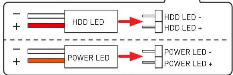
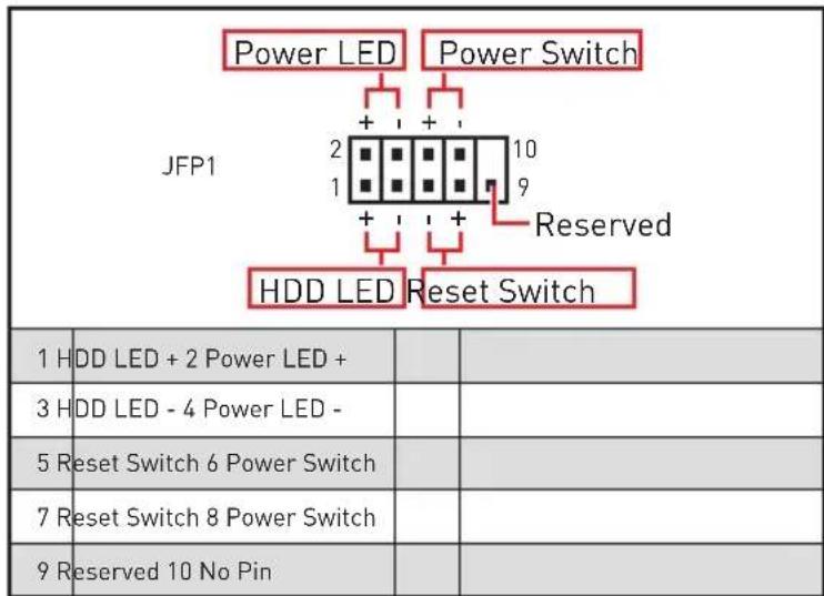
| 1 | HDD LED + | 2 | Power LED + |
| 3 | HDD LED - | 4 | Power LED - |
| 5 | Reset Switch | 6 | Power Switch |
| 7 | Reset Switch | 8 | Power Switch |
| 9 | Reserved | 10 | No Pin |
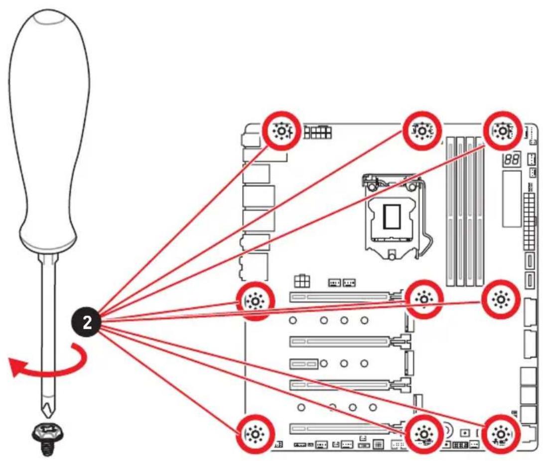
Installing the Motherboard/ Installation des Motherboards/ Installer la carte mère/YcTaHOBKa MaTePNHcKo ПlaTbI
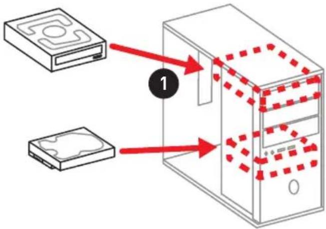
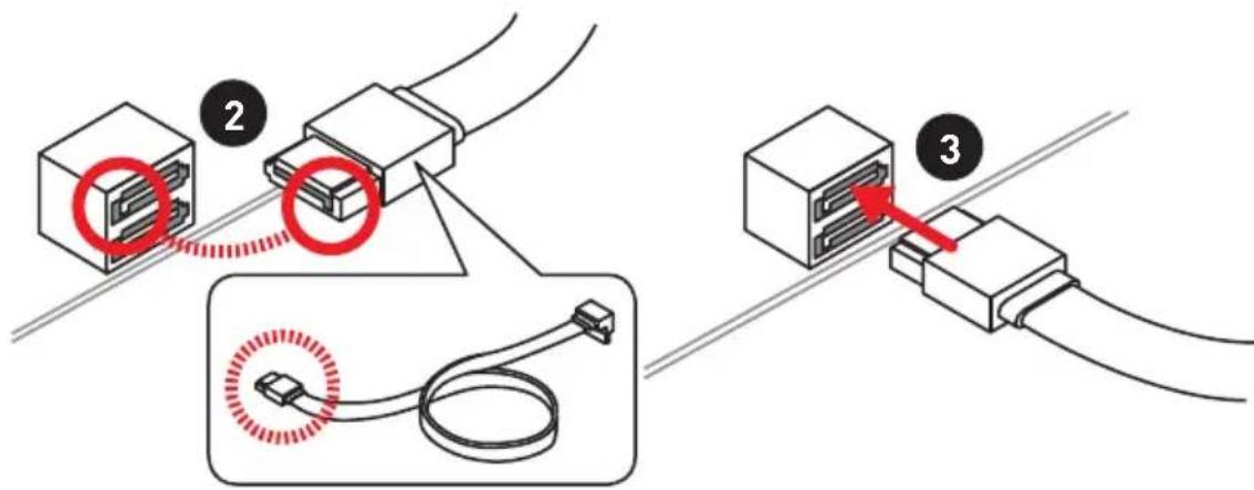
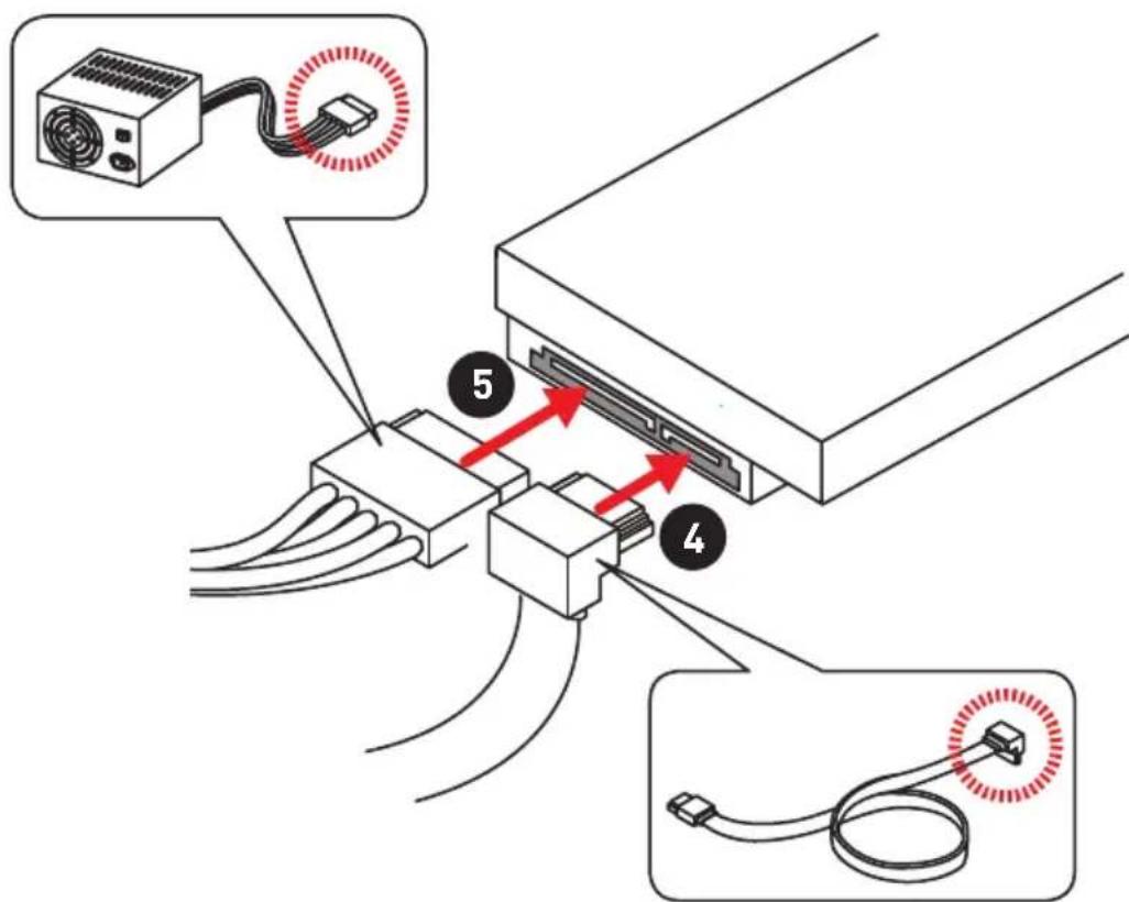
Installing SATA Drives/ Installation der SATA-Laufwerke/ Installer le disque dur SATA/Установka дись SATA


http://youtu.be/RZsMpqxythc
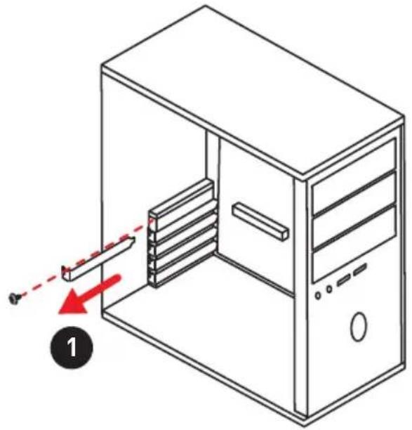
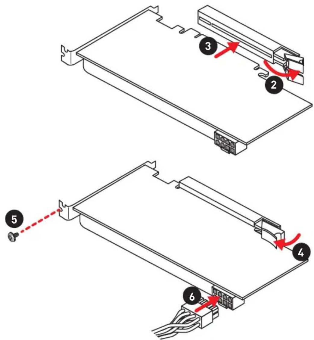
Installing a Graphics Card/ Einbau der Grafikkarte/ Installer une carte graphique/Установka Ди stickpeТонь ВдeOKapТы


http://youtu.be/mG0GZpr9w_A
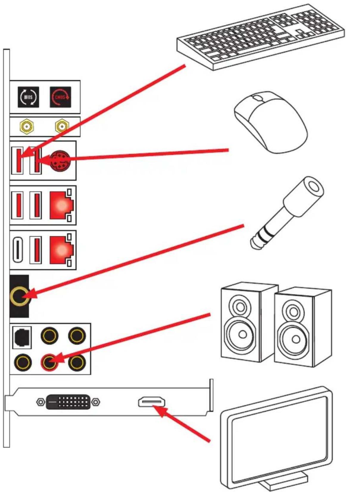
Connecting Peripheral Devices/ Peripheriegeräte/ Connector un périhérique anschliessen/ Повлочnéперифэрийнсы устroduстВ
Connecting the Power Connectors/ Stromanschlüsse anschliessen/ Connector les cables du module d'alimentation/ Podкlioуне pa3beMoB птань


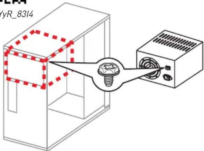
http://youtu.be/gkDyR_8314
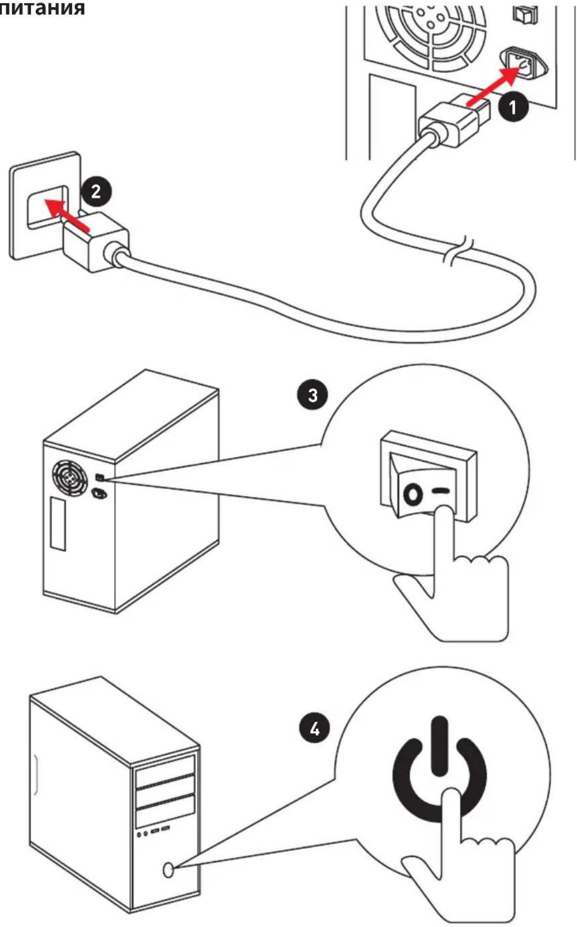
Power On/ Einschalten/ Mettre sous-tension/Вклоченье
ПИТАнь
Contents
Safety Information 3
Specifications 4
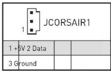
JCORSAIR1 Connector Specification 10
Package contents 11
Rear I/O Panel. 12
Overview of Components 16
LAN Port LED Status Table. 12
Audio Ports Configuration 12
Realtek Audio Console 13
Installing Antennas 15
CPU Socket 17
DIMM Slots 18
PCI_E1~5:PCIe Expansion Slots 19
PEGSW1:PCIeCeaseFireSwitch 20
U2_1: U.2 Connector 22
M2_1~3: M.2 Slots (Key M) 23
V-Check Points 25
Installing the M.2 Xpander-Z 26
SATA1-6: SATA 6Gb/s Connectors 27
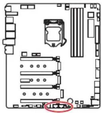
JFP1, JFP2: Front Panel Connectors 29
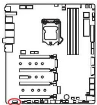
JAUD1: Front Audio Connector 29
CPU_PWR1~2,ATX_PWR1,PCIE_PWR1:Power Connectors. 30
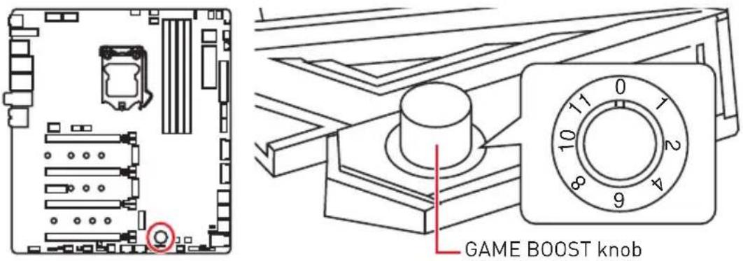
OC1: GAME BOOST Knob 31
JBLK_U1, JRATIO_U1: Base clock Plus, Ratio Plus connectors 32
OC_FS1: OC Force Enter BIOS Button 32
OC_RT2: OC Retry Button 32
T_SEN1~2: Thermal Sensor Connectors 33
JSLOW1: Slow Mode Booting Jumper 33
CPU_FAN1, PUMP_FAN1, SYS_FAN1~8: Fan Connectors. 34
W_FLOW1: Water Flow Meter Connector 35
JUSB1~2: USB 3.1 Gen2 Type-C Connectors 35
JUSB3-4: USB 3.1 Gen1 Connectors 36
JUSB5-6: USB 2.0 Connectors 37
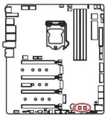
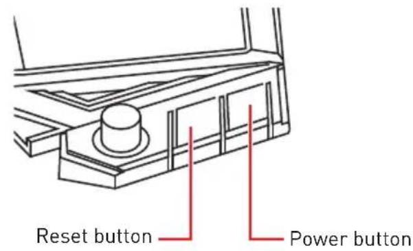
POWER1, RESET1: Power Button, Reset Button 38
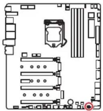
JBAT1: Clear CMOS (Reset BIOS) Jumper 38
JCI1:Chassis Intrusion Connector 39
BIOS_SW1: Multi-BIOS Switch 40
JRGB1,JRAINBOW1~2:RGBLED connectors 41
JCORSAIR1: CORSAIR Connector 42
DYNAMIC DASHBOARD 43
DYNAMIC DASHBOARD Status Table 43
Onboard LEDs 44
EZ Debug LED 44
DIMM LEDs 44
Fan LEDs 44
Multi-BIOS LEDs. 45
XMPLED 45
JPWRLED1: LED power input. 45
Debug Code LED 46
Hexadecimal Character Table 46
Boot Phases 46
Debug Code LED Table 46
ACPI States Codes 51
CPU Temperature 51
Installing OS, Drivers & Utilities 52
Installing Windows 10 52
Installing Drivers 52
Installing Utilities 52
BIOS Setup 53
EnteringBIOS Setup 53
ResettingBIOS 54
Updating BIOS 54
EZ Mode 56
Advanced Mode 58
OC Menu. 59
Safety Information
-
The components included in this package are prone to damage from electrostatic discharge (ESD). Please adhere to the following instructions to ensure successful computer assembly.
-
Ensure that all components are securely connected. Loose connections may cause the computer to not recognize a component or fail to start.
-
Hold the motherboard by the edges to avoid touching sensitive components.
-
It is recommended to wear an electrostatic discharge (ESD) wrist strap when handling the motherboard to prevent electrostatic damage. If an ESD wrist strap is not available, discharge yourself of static electricity by touching another metal object before handling the motherboard.
-
Store the motherboard in an electrostatic shielding container or on an anti-static pad whenever the motherboard is not installed.
-
Before turning on the computer, ensure that there are no loose screws or metal components on the motherboard or anywhere within the computer case.
-
Do not boot the computer before installation is completed. This could cause permanent damage to the components as well as injury to the user.
-
If you need help during any installation step, please consult a certified computer technician.
-
Always turn off the power supply and unplug the power cord from the power outlet before installing or removing any computer component.
-
Keep this user guide for future reference.
-
Keep this motherboard away from humidity.
-
Make sure that your electrical outlet provides the same voltage as is indicated on the PSU, before connecting the PSU to the electrical outlet.
-
Place the power cord such a way that people can not step on it. Do not place anything over the power cord.
-
All cautions and warnings on the motherboard should be noted.
-
If any of the following situations arises, get the motherboard checked by service personnel:
Liquid has penetrated into the computer.
The motherboard has been exposed to moisture.
- The motherboard does not work well or you can not get it work according to user guide.
The motherboard has been dropped and damaged.
The motherboard has obvious sign of breakage.
- Do not leave this motherboard in an environment above 60^ [140^] , it may damage the motherboard.
Specifications
Continued on next page
| CPU | Supports Intel® Core™ 9000 Series family/ 8th Gen Intel® Core™ / Pentium® Gold / Celeron® processors for LGA 1151 socket * Please go to www.intel.com for more compatibility information. |
| Chipset Intel | ® Z390 Chipset |
| Memory | · 4x DDR4 memory slots, support up to 64GB* · Supports DDR4 4600(OC)/ 4533(OC)/ 4500(OC)/ 4400(OC)/ 4300(OC)/ 4266(OC)/ 4200(OC)/ 4133(OC)/ 4000(OC)/ 3866(OC)/ 3733(OC)/ 3600(OC)/ 3466(OC)/ 3400(OC)/ 3333(OC)/ 3300(OC)/ 3200(OC)/ 3000(OC)/ 2800(OC)/ 2666/ 2400/ 2133 MHz* · Supports Dual-Channel mode · Supports non-ECC, un-buffered memory · Supports IATExtreme Memory Profile (XMP) * Please refer www.msi.com for more information on compatible memory. |
| Expansion Slot | · 4x PCIe 3.0 x16 slots* · 1x PCIe 3.0 x1 slot * Please refer to page 19 for details. |
| Multi-GPU | · Supports 2-Way NVIDIA™ Technology · Supports 4-Way AMD CrossFire™ Technology |
| Storage | Intel® Z390 Chipset · 6x SATA 6Gb/s ports* · 3x M.2 slots [Key M]* · M2_1 & M2_3 support up to PCIe 3.0 x4 and SATA 6Gb 2242/ 2260/ 2280/ 22110 storage devices · M2_2 supports up to PCIe 3.0 x4 and SATA 6Gb/s, 2242 2260/ 2280 storage devices · Intel@ptane™ Memory Ready · 1x U.2 port* · Supports PCIe 3.0 x4 NVMe storage * M.2_2 slot, U.2 port and SATA ports share the bandwidth. Please refer to page 27 for details. ** Before using Intel® Optane™ memory modules, please ensure that you have updated the drivers and BIOS to the latest version from MSI website. |
Continued from previous page
| RAID | Intel® Z390 Chipset Supports RAID 0, RAID1, RAID 5 and RAID 10 for SATA storage devices Supports RAID 0, RAID 1 and RAID5 for M.2 PCIe storage devices |
| LAN • 2x Killer | ® E2500 Gigabit LAN controllers |
| Wiresless LAN & Bluetooth® | Killer®1550 Chipset • The Wireless module is pre-install in the M2_4 (Key-E) slot • Supports Wi-Fi 5, 2x2, Dual Band, (2.4GHz, 5GHz) up to 1.73 Gbps speed • Supports Bluetooth |
| USB | • InA390 Chipset • 6x USB 3.1 Gen2 (SuperSpeed USB 10Gbps) ports (1 Type-C and 3 Type-A ports on the back panel, 2 Type-C internal connectors) • 4x USB 2.0 (High-speed USB) ports through the internal USB connectors • ASM@ASM1042 Chipset • 2x USB 3.1 Gen1 (SuperSpeed USB) ports on the back panel • ASM@ASM1074 Chipset • 4x USB 3.1 Gen1 (SuperSpeed USB) ports available through the internal USB connectors |
| Audio | • 2x Realtek C1220 Codec • 7.1-Channel High Definition Audio • Supports S/PDIF output • ESE9018 Codec • Supports 6.3mm Gold-plated stereo headphone out |
Continued on next page
Continued from previous page
Continued on next page
| Back Panel Connectors | · 1x Flash BIOS Button · 1x Clear CMOS button · 2x Wi-Fi Antenna connectors · 1x PS/2 keyboard/ mouse combo port · 2x USB 3.1 Gen1 Type-A ports · 2x LAN (RJ45) ports · 3x USB 3.1 Gen2 Type-A ports · 1x USB 3.1 Gen2 Type-C port · 1x 6.3mm Gold-plated stereo headphone jack · 5x OFC audio jacks · 1x Optical S/PDIF OUT connector |
| Internal Connectors | · 1x 24-pin ATX main power connector · 2x 8-pin ATX 12V power connectors · 1x 6-pin ATX PCIe power connector · 6x SATA 6Gb/s connectors · 3x M.2 slots (M-Key) · 1x U.2 port · 2x USB 3.1 Gen2 Type-C ports · 2x USB 3.1 Gen1 connectors (supports additional 4 USB 3 Gen1 ports) · 2x USB 2.0 connectors (supports additional 4 USB 2.0 ports) · 1x 4-pin CPU fan connector · 1x 4-pin Water Pump connector · 8x 4-pin system fan connectors · 1x 3-pin Water Flow connector · 1x Front panel audio connector · 2x System panel connectors · 1x Chassis Intrusion connector · 2x 2-pin Thermal Sensors connectors · 1x 4-pin RGB LED connector · 2x 3-pin RAINBOW LED connectors · 1x 3-pin CORSAIR LED connector |
Continued from previous page
| Internal Buttons | • 1x GAME BOOST knob • 1x OC retry button • 1x OC force enter BIOS button • 1x Power button • 1x Reset button |
| Internal Pinheader | • 1x JBLK_U1 pinheader • 1x JRATIO_U1 pinheader |
| Switches | • 1x Multi-BIOS switch • 1x PCIe CeaseFire switch |
| Jumper • 1x Slow mode jumper | |
| Debug LED | • 1x 2-Digit Debug Code LED • 4x EZ Debug LED |
| Display Panel | DYNAMIC DASHBOARD • Displays system information |
| I/O Controller NUVOTON NCT6797 Controller Chip | |
| Hardware Monitor | • CPU/System temperature detection • CPU/System fan speed detection • CPU/System fan speed control |
| Form Factor | • E-ATX Form Factor • 12 in. x 10.7 in. (30.5 cm x 27.2 cm) |
| BIOS Features | • Dual BIOS • 2x 128 Mb flash • UEFI AMI BIOS • ACPI 6.1, SMBIOS 2.8 • Multi-language |
Continued on next page
Continued from previous page
| Software | • Drivers • DRAGON CENTER • MYSTIC LIGHT • Killer Control Center • Nahimic Audio • CPU-Z MSI GAMING • MSI App Player (BlueStacks) • IRTExtreme Tuning Utility • Google Chrome™, Google Toolbar, Google Drive • Norton™ Internet Security Solution |
| Dragon Center Features | • GAME OPTIMIZATION • OC Performance • Hardware Monitor • Eyerest • LAN Manager • Live Update Please refer to http://download.msi.com/manual/mb/DRAGONCENTER2.pdf for more details. |
| Special Features | • Audio • Xtreme Audio DAC • Nahimic 3 • Network • Killer TripleShot • GAMING LAN with Killer LAN Manager • Killer WiFi • Storage • Turbo U.2 • Triple Turbo M.2 |
Continued on next page
Continued from previous page
| Special Features | ·Fan ·Pump Fan ·GAMING Fan Control ·LED ·Mystic Light 3 ·Mystic Light Extension (RGB) ·Mystic Light Extension (RAINBOW) ·Mystic Light Extension (CORSAIR) ·Mystic Light Sync ·EZ DEBUG LED ·Protection ·DDR4 Steel Armor ·M.2 Shield 3 ·PCIe Steel Armor ·U.2 Steel Armor ·Performance ·Exclusive ESS SABRE HiFi DAC for lossless, high-quality audio ·Multi GPU-SLI Technology ·Multi GPU-CrossFire Technology ·DDR4 Boost ·GAME Boost ·Streaming Boost ·OC Engine ·Lightning USB ·Front Lightning USB ·USB with type A+C ·Stability ·7000+ Quality Test |
Continued on next page
Continued from previous page
| Special Features | • VR • VR Ready • Gamer Experience • GAMING HOTKEY • GAMING MOUSE Control • BIOS • Click BIOS 5 • Flash BIOS Button • Dual BIOS • Certification • Quadro SLI Ready • Quadro Ready • GAMING Certified |
JCORSAIR1 Connector Specification
| Supporting CORSAIR RGB Products Maximum connection | |
| Lighting Node PRO LED Strip | 20* * 20% brightness is recommended when the number of LED strips exceeds 8. |
| HD120 RGB Fan 6 | |
| SP120 RGB Fan 6 | |
| LL120 RGB Fan 6 | |
Package contents
Please check the contents of your motherboard package. It should contain:
| Motherboard MEG Z39 | 0 GODLIKE | |
| Cable | SATA 6Gb/s Cables 6 | |
| 1 to 2 RGB LED Extension Y Cable 80cm 1 | ||
| CORSAIR RGB LED Extension Cable 50cm 1 | ||
| RAINBOW RGB LED Extension Cable 80cm 2 | ||
| CORSAIR to RAINBOW RGB Extension Cable 10cm 1 | ||
| Thermistor Cable 2 | ||
| Accessories | Antenna Set 1 | |
| M.2 Xpander-Z 1 | ||
| Streaming Boost 1 | ||
| SLI HB BRIDGE L 1 | ||
| 6.3mm Audio Adapters 1 | ||
| Case Badge 1 | ||
| SATA Cable Labels 1 | ||
| Product Registration Card | 1 | |
| 8.5H M.2 screws | 3 | |
| Application DVD | Driver DVD | 1 |
| Documentation | User Manual | 1 |
| Quick Guide 1 | ||
| Quick Installation Guide | 1 | |

Important
If any of the above items are damaged or missing, please contact your retailer.
Rear I/O Panel
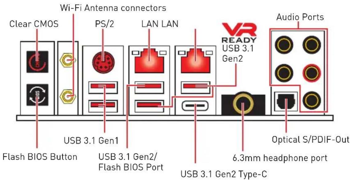
- Clear CMOS button - Power off your computer. Press and hold the Clear CMOS button for about 5-10 seconds to reset BIOS to default values.
- Flash BIOS Button/Port - Please refer to page 75 for Updating BIOS with Flash BIOS Button.
- 6.3mm headphone port - This port is used for connecting the headphone.
LAN Port LED Status Table
| Link/ Activity LED | Speed LED | ||
| Status Description | Status Description | ||
| Off No link | Off 10 Mbps connection | ||
| Yellow Linked | Green 100 Mbps connection | ||
| Blinking Data activity | Orange 1 Gbps connection | ||
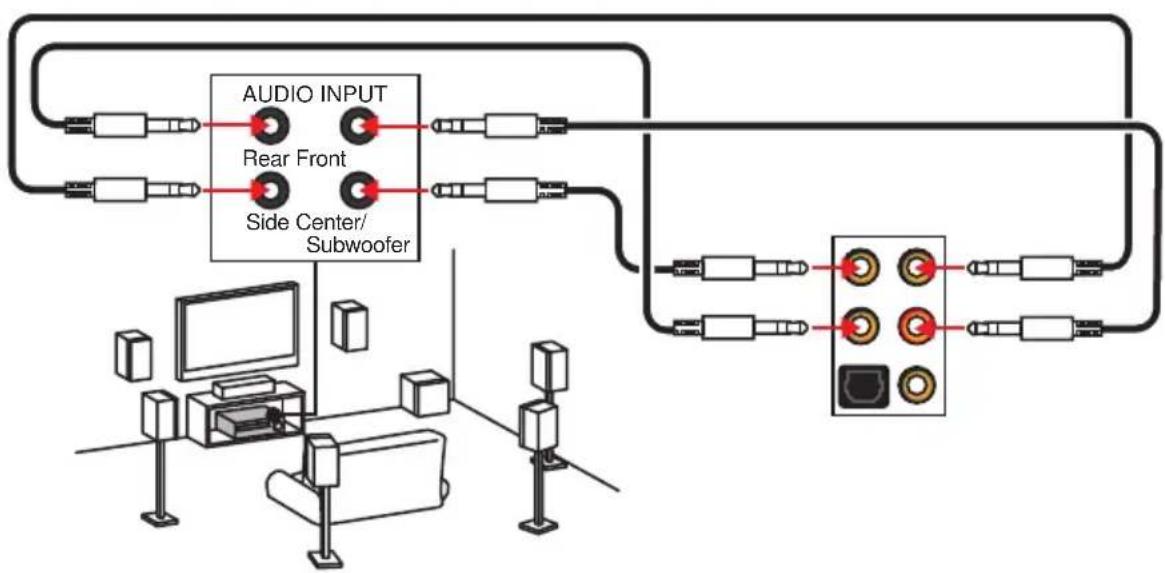
Audio Ports Configuration
| Audio Ports | Channel | |||
| 24 | 68 | |||
| Center/Subwoofer Out | ||||
| Rear Speaker Out | ||||
| Line-In/ Side Speaker Out | ||||
| Line-Out/ Front Speaker Out | ||||
| Mic In | ||||
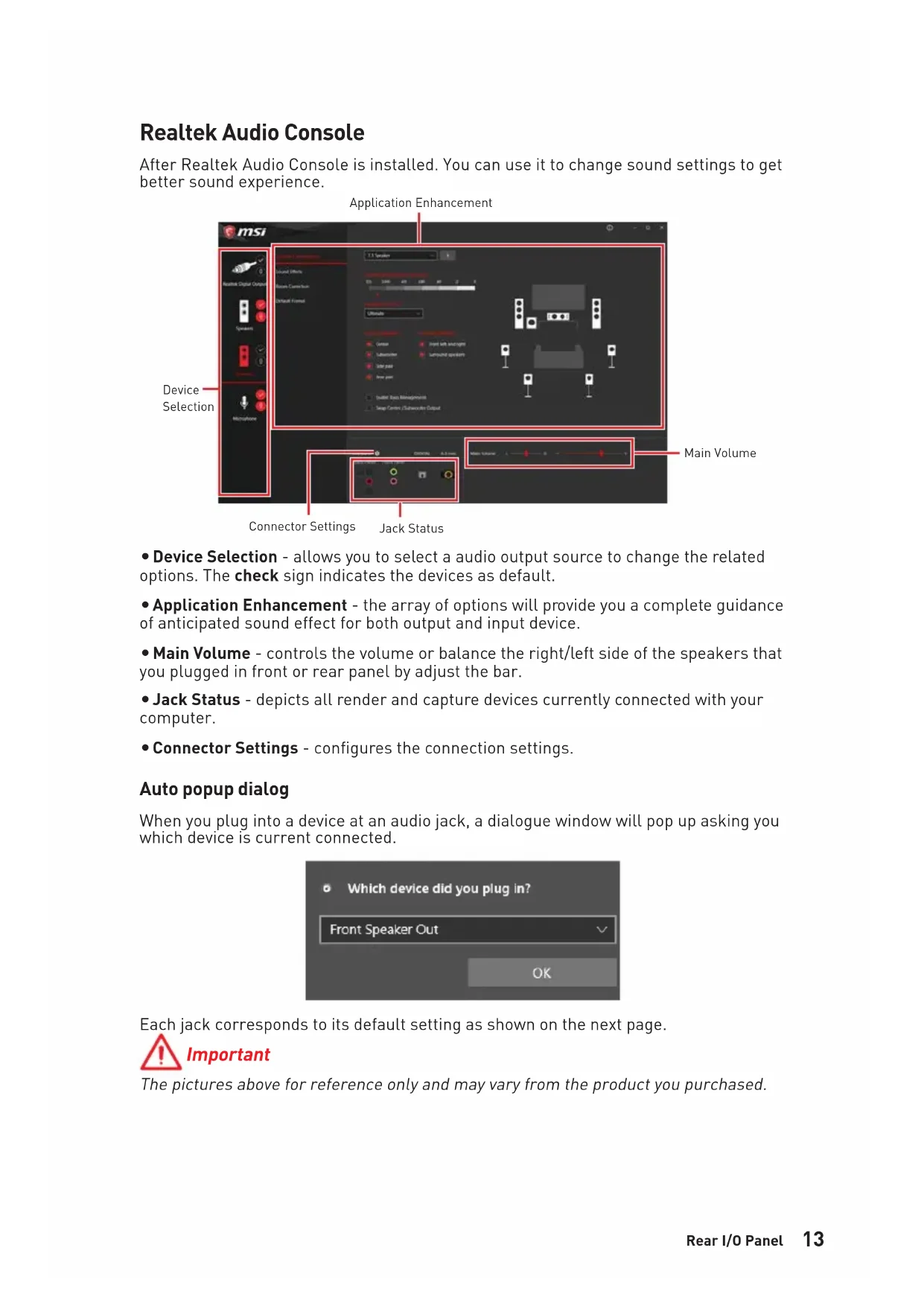
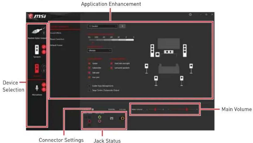
Realtek Audio Console
After Realtek Audio Console is installed. You can use it to change sound settings to get better sound experience.
-
Device Selection - allows you to select a audio output source to change the related options. The check sign indicates the devices as default.
-
Application Enhancement - the array of options will provide you a complete guidance of anticipated sound effect for both output and input device.
-
Main Volume - controls the volume or balance the right/left side of the speakers that you plugged in front or rear panel by adjust the bar.
-
Jack Status - depicts all render and capture devices currently connected with your computer.
-
Connector Settings - configures the connection settings.
Auto popup dialog
When you plug into a device at an audio jack, a dialogue window will pop up asking you which device is current connected.

Each jack corresponds to its default setting as shown on the next page.
Important
The pictures above for reference only and may vary from the product you purchased.
Audio jacks to headphone and microphone diagram

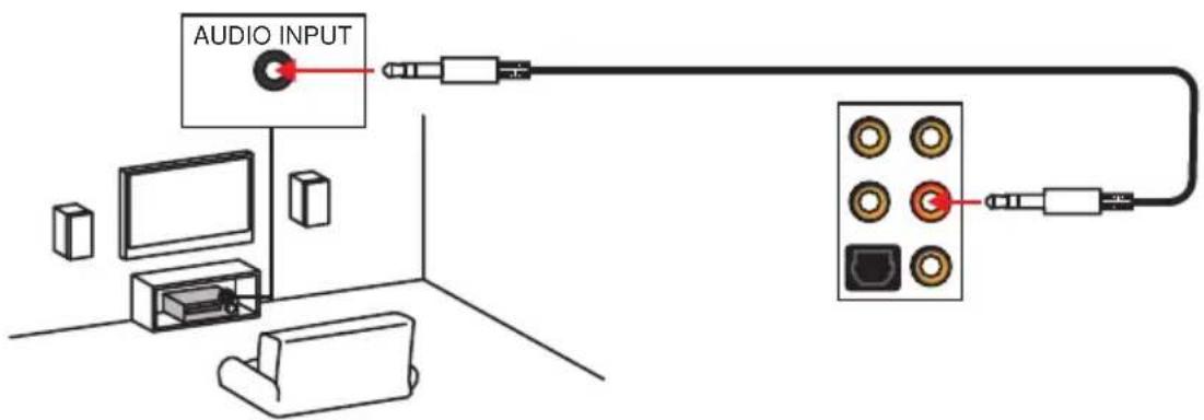
Audio jacks to stereo speakers diagram
Audio jacks to 7.1-channel speakers diagram
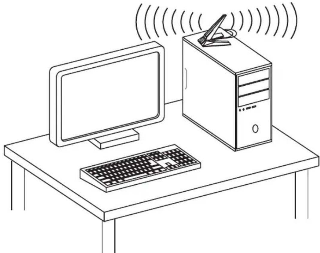
Installing Antennas
- Combine the antenna with the base.
- Screw two antenna cables tight to the WiFi antenna connectors as shown.
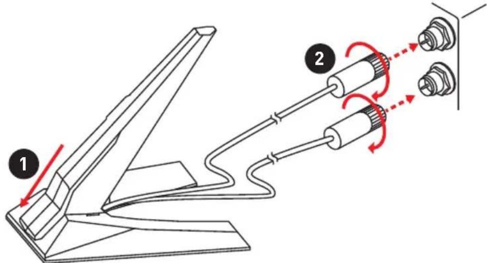
- Place the antenna as high as possible.
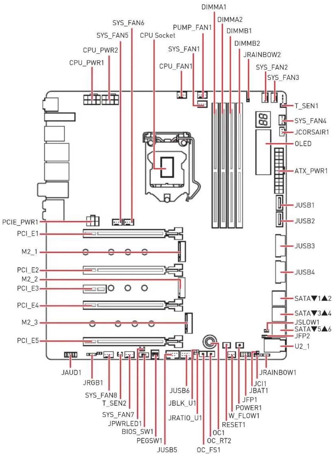
Overview of Components
CPU Socket
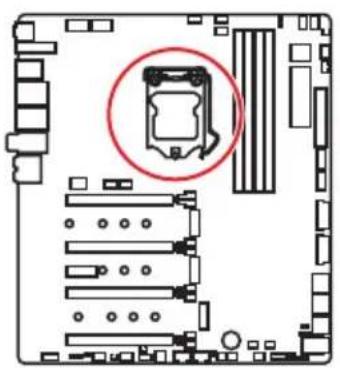
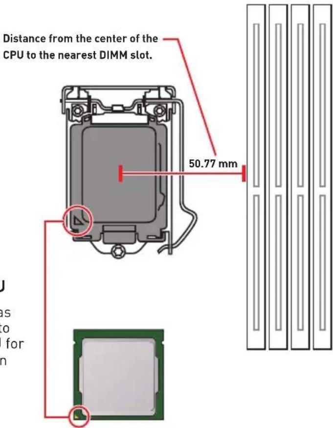
Introduction to the LGA 1151 CPU
The surface of the LGA 1151 CPU has two notches and a golden triangle to assist in correctly lining up the CPU for motherboard placement. The golden triangle is the Pin 1 indicator.
Important
Always unplug the power cord from the power outlet before installing or removing the CPU.
Please retain the CPU protective cap after installing the processor. MSI will deal with Return Merchandise Authorization (RMA) requests if only the motherboard comes with the protective cap on the CPU socket.
When installing a CPU, always remember to install a CPU heatsink. A CPU heatsink is necessary to prevent overheating and maintain system stability.
Confirm that the CPU heatsink has formed a tight seal with the CPU before booting your system.
Overheating can seriously damage the CPU and motherboard. Always make sure the cooling fans work properly to protect the CPU from overheating. Be sure to apply an even layer of thermal paste (or thermal tape) between the CPU and the heatsink to enhance heat dissipation.
Whenever the CPU is not installed, always protect the CPU socket pins by covering the socket with the plastic cap.
If you purchased a separate CPU and heatsink/ cooler, Please refer to the documentation in the heatsink/ cooler package for more details about installation.
This motherboard is designed to support overclocking. Before attempting to overclock, please make sure that all other system components can tolerate overclocking. Any attempt to operate beyond product specifications is not recommended. MSI® does not guarantee the damages or risks caused by inadequate operation beyond product specifications.
DIMM Slots

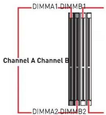

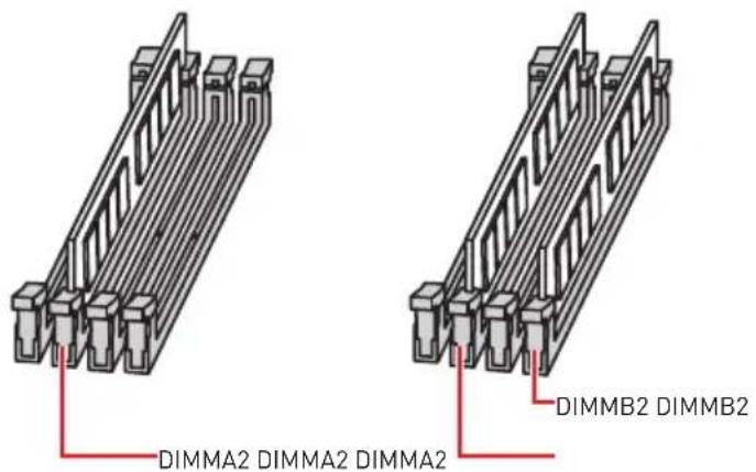
Memory module installation recommendation
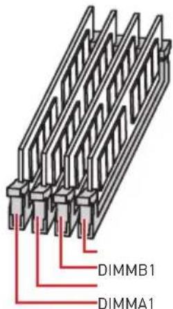
Important
Always insert memory modules in the DIMMA2 slot first.
Due to chipset resource usage, the available capacity of memory will be a little less than the amount of installed.
Based on Intel CPU specification, the Memory DIMM voltage below 1.35V is suggested to protect the CPU.
Please note that the maximum capacity of addressable memory is 4GB or less for 32-bit Windows OS due to the memory address limitation. Therefore, we recommended that you to install 64-bit Windows OS if you want to install more than 4GB memory on the motherboard.
Some memory may operate at a lower frequency than the marked value when overclocking due to the memory frequency operates dependent on its Serial Presence Detect (SPD). Go to BIOS and find the Memory Try It! to set the memory frequency if you want to operate the memory at the marked or at a higher frequency.
It is recommended to use a more efficient memory cooling system for full DIMMs installation or overclocking.
The stability and compatibility of installed memory module depend on installed CPU and devices when overclocking.
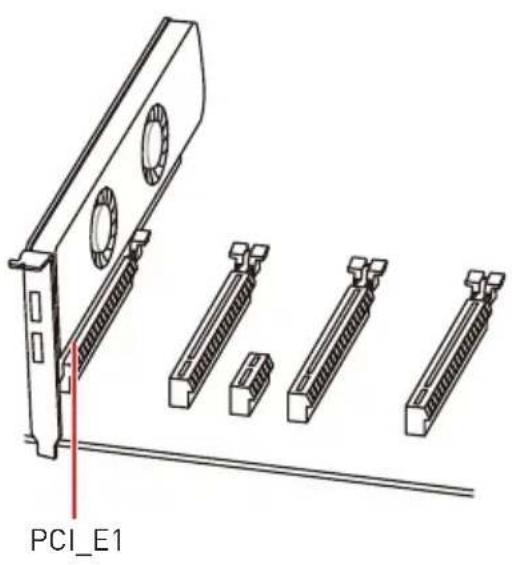
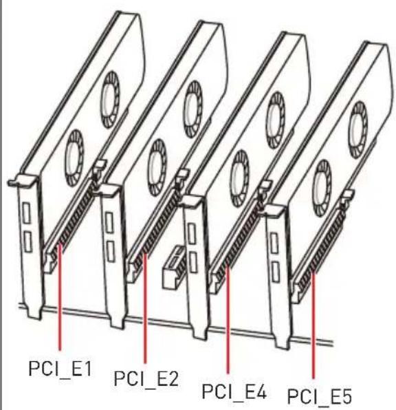
PCI_E1~5: PCIe Expansion Slots

PCI_E1: PCIe 3.0 x16 [CPU lanes]
PCI_E2: PCIe 3.0 x4 (CPU lanes)
PCI_E3: PCIe 3.0 x1 (PCH lanes)
PCI_E4: PCIe 3.0 x8 (CPU lanes)
PCI_E5: PCIe 3.0 x4 (PCH lanes)
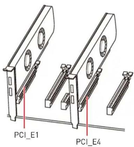
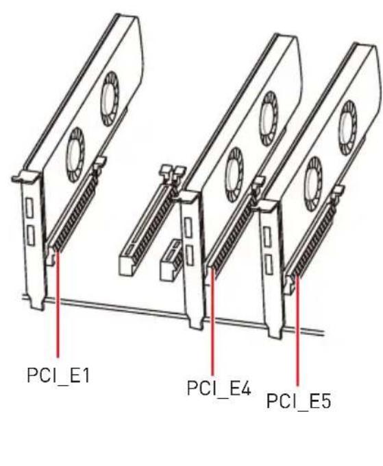
Multiple graphics cards installation recommendation
| Graphics Card Single 2-Way 3-Way* 4-Way* | ||||
| PCI_E1 @ 3.0 | x16 @ 3.0 x8 @ 3.0 x8 @ | 3.0 x8 | ||
| PCI_E2 Empty | Empty Empty @ 3.0 x4 | |||
| PCI_E3 3.0 x1 | 3.0 x1 3.0 x1 3.0 x1 | |||
| PCI_E4 Empty | @ 3.0 x8 @ 3.0 x8 @3.0 | x4 | ||
| PCI_E5 3.0 x4 | 3.0 x4 @ 3.0 x4 @3.0 x4 | |||
(@: graphics card slot, *: CrossFire only)
! Important
If you install a large and heavy graphics card, you need to use a tool such as MSI Gaming Series Graphics Card Bolster to support its weight and to prevent deformation of the slot.
For a single PCIe x16 expansion card installation with optimum performance, using the PCI_E1 slot is recommended.
When adding or removing expansion cards, always turn off the power supply and unplug the power supply power cable from the power outlet. Read the expansion card's documentation to check for any necessary additional hardware or software changes.
The M2_3 will be unavailable when installing PCIe device in to PCI_E5 slot.
PEGSW1: PCIe CeaseFire Switch
The PCIe CeaseFire switch allows you to enable/ disable the PCIe slots (by CPU lanes) conveniently and directly.
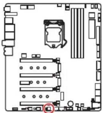
| Slots | ON 1 2 3 | ON 1 2 3 | ON 1 2 3 | ON 1 2 3 |
| PCI_E1 | ✓ ✓ | ✓ — | ||
| PCI_E2 | ✓ — | — — | ||
| PCI_E4 | ✓ ✓ | — — |
:enabled,——:disabled]
Installing SLI graphics cards
For power supply recommendations for SLI configurations, please refer to the user guide of your graphics card to make sure you meet all the system requirements.
To install SLI graphics cards:
- Turn off your computer and disconnect the power cord, install two graphics cards into the PCI_E1 and PCI_E4 slots.
- Connect the two cards together using the SLI Bridge Connector.
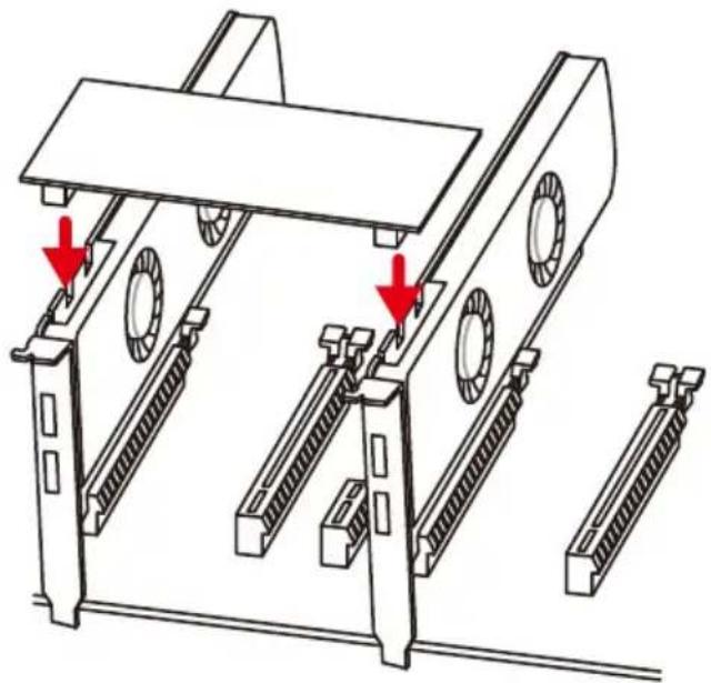
- Connect all PCIe power connectors of the graphics cards.
- Reconnect the power cord, power up the computer and install the drivers and software included in your graphics card package.
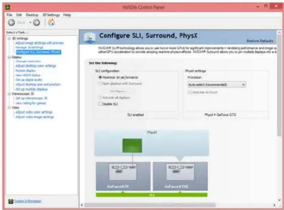
- Right-click the Windows desktop and select NVIDIA Control Panel from the menu, click on Configure SLI, Surround, PhysX in the left task pane and select Maximize 3D performance in the SLI configuration menu, and then click Apply.
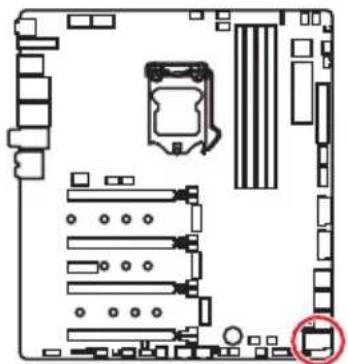
U2_1: U.2 Connector
This connector is a U.2 interface port. Each connector can connect to one PCIe 3.0 x4 NVMe storage device.


Video Demonstration
Watch the video to learn how to Install U.2 SSD. http://youtu.be/KgFvKDxymvw
Installing U.2 SSD
- Connect the U.2 cable to the U.2 connector on the motherboard.
- Connect the U.2 cable to the U.2 SSD.
- Connect the U.2 cable to power adapter cable.
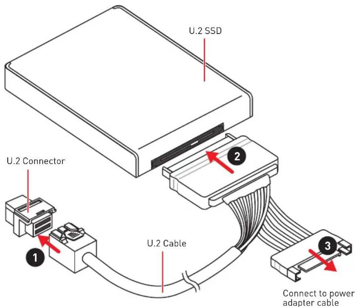

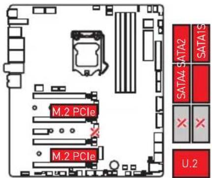
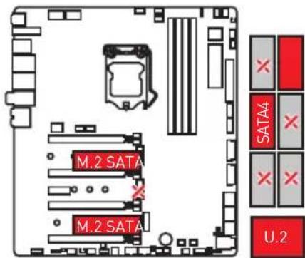
The M2_2, SATA5 and SATA6 will be unavailable when installing U.2 device into U.2 port.
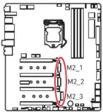
M2_1~3: M.2 Slots (Key M)
! Important
Intel® RST only supports PCIe M.2 SSD with UEFI ROM.
Intel® Optane™ Memory Ready for all M.2 slots.
Installing M.2 module
- Loosen the screws of M.2 SHIELD FROZR.
- Lift the M.2 SHIELD FROZR and remove the protective films from the thermal pads.
-
Each M.2 slot is equipped with two screws and mounting poles, one for securing the M.2 SHIELD FROZR heatsink and the other one for shorter M.2 SSD. To avoid damage to the M.2 SSD. If your M.2 SSD length is the same as the M.2 slot, remove the screw and mounting pole below the M.2 SSD, leaving only the screw and mounting pole for securing the M.2 SHIELD FROZR heatsink.
-
There are two thermal pads on each M.2 slot base plate. The thermal pad-2 is fixed on the M.2 board and should not be removed.
For double-side M.2 SSD, completely remove the thermal pad-1 and protection films.
For single-side M.2 SSD, remove the two thermal protection films from pad-1, then re-stick it to the thermal pad-2.
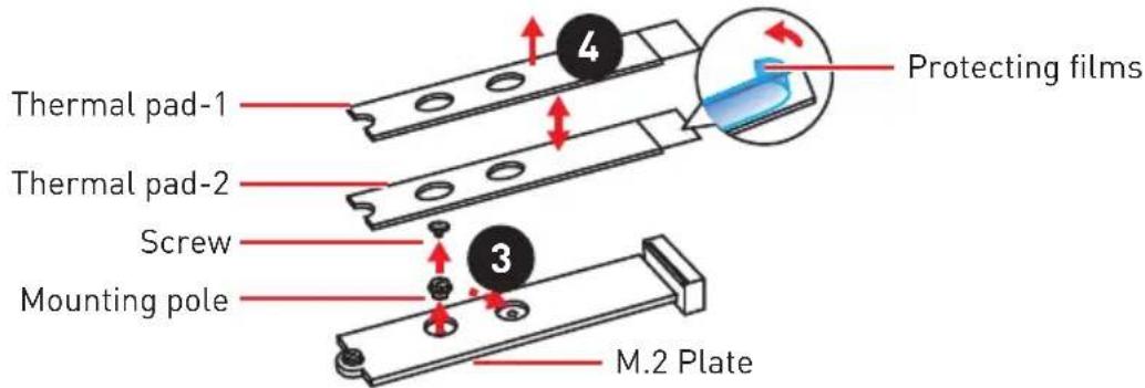
Pictures shown are for illustration purpose only and may differ from the actual plates and thermal pads.
- Move the position of the mounting poles according to your M.2 SSDs length if need.
- Insert your M.2 SSDs into the M.2 slots at a 30-degree angle.
- If the M.2 SSD is shorter than the M.2 SHIELD FROZR heatsink, place the screw in the notch on the trailing edge of the M.2 module and tighten it into the mounting pole.
- Insert the M.2 SHIELD FROZR heatsink shaft into the groove.
- PushtheM.2 SHIELD FROZR heatsink down.
- Secure the M.2 SHIELD FROZR heatsink onto the mounting pole.
V-Check Points
These voltage checkpoints are used to measure the current system voltages. A multimeter (not included) will be required to check voltages. To measure voltage, place test leads on the GND (screw mounting hole) and a V-Check Point. Please refer to the manual of your multimeter for more information.
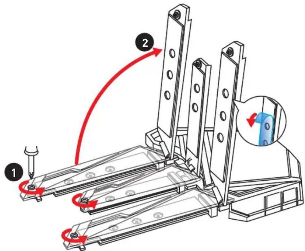
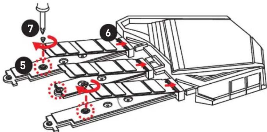
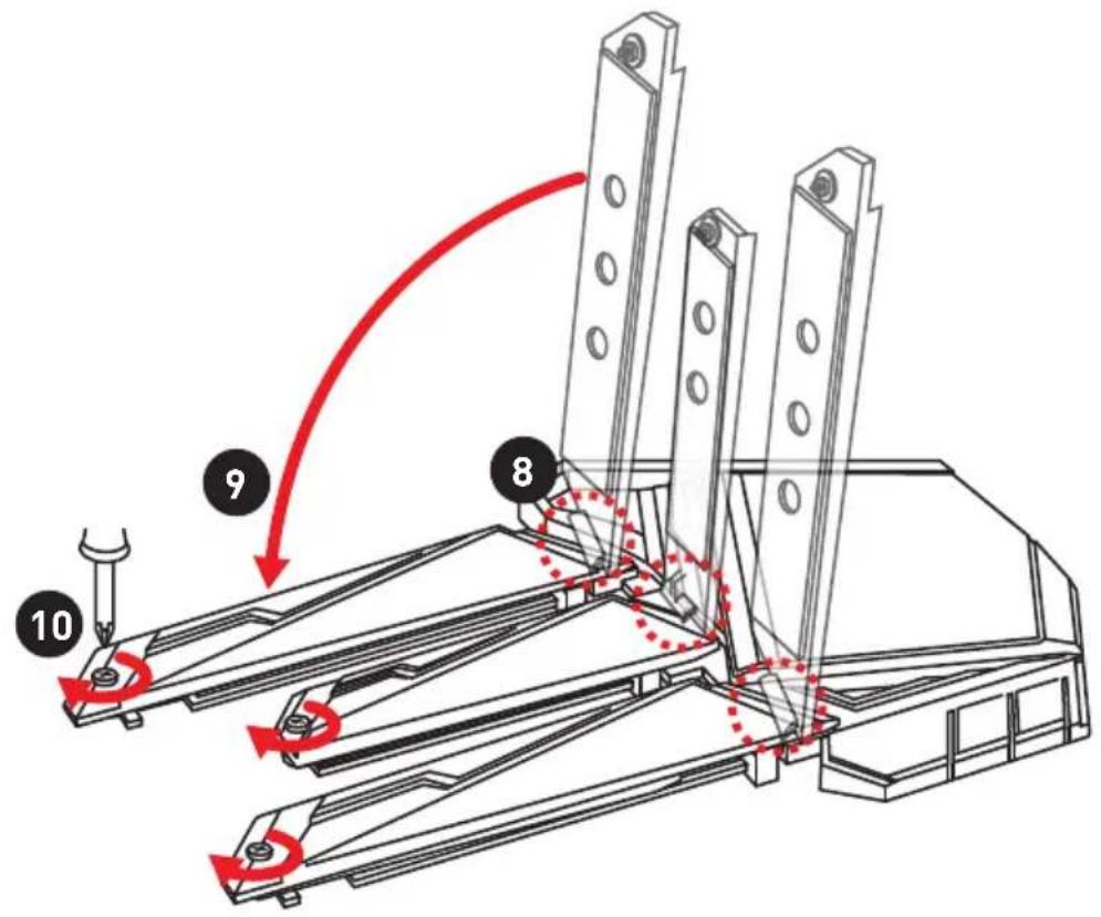
Installing the M.2 Xpander-Z
The M.2 Xpander-Z card provide two M.2 Key-M slots.
To install the M.2 Xpander-Z card:
- Remove the screws from the mounting poles.
- Lift the M.2 Shields and remove the protective films and the round rubbers from the thermal pads.
- Move the mounting poles position according to your M.2 SSDs length.
- Insert your M.2 SSDs into the M.2 slots at a 30-degree angle.
- Push the M.2 SSDs and the M.2 Shields down and secure them onto the mounting poles.
- Insert the M.2 Xpander-Z into one PCIe slot (PCI_E2 or PCI_E4).
- Use the screw to secure the M.2 Xpander-Z.
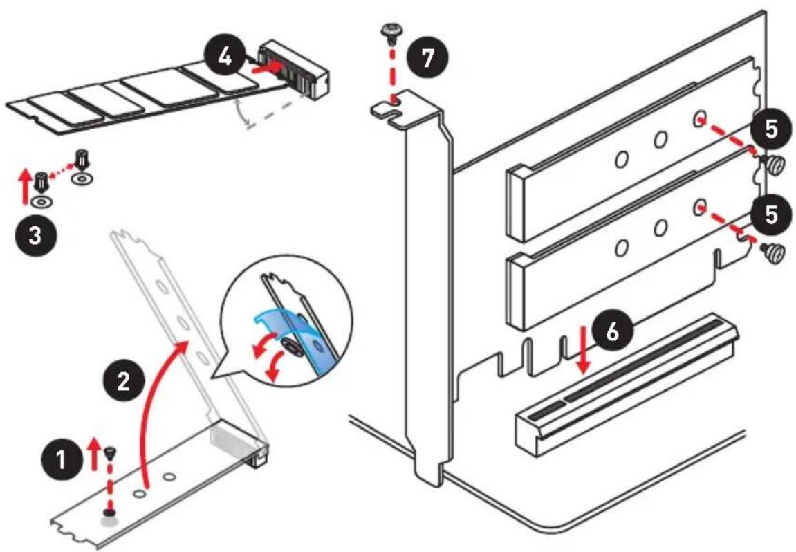
Important
When you installed the Xpander-Z card in PCI_E2 then PCI_E4 will be unavailable, If Xpander-Z card is installed in PCI_E4 then PCI_E2 will be unavailable.
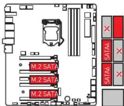
SATA1~6: SATA 6Gb/s Connectors
These connectors are SATA 6Gb/s interface ports. Each connector can connect to one SATA device.
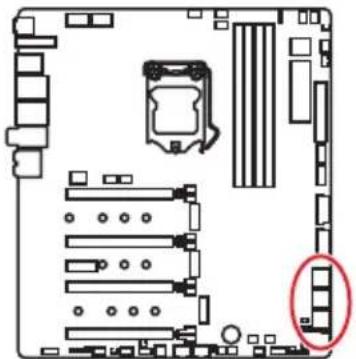

Important
Please do not fold the SATA cable at a 90-degree angle. Data loss may result during transmission otherwise.
SATA cables have identical plugs on either sides of the cable. However, it is recommended that the flat connector be connected to the motherboard for space saving purposes.
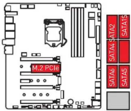
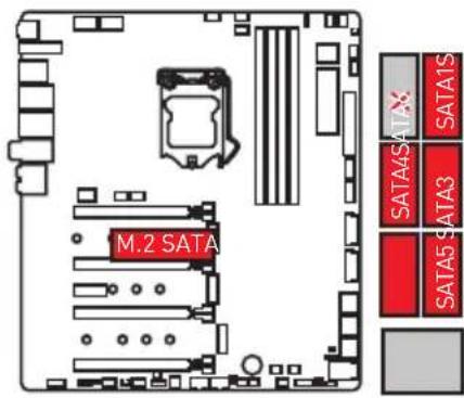
M.2, SATA and U.2 combination table
| Slot Combination | ||
| M2_1 PCIe SATA | ||
| SATA1 √ | √ | |
| SATA2 √ | — | |
| U2_1 Empty Installed | ||||
| M2_2 PCIe SATA Empty — | ||||
| SATA5 | — | — | ✓ | — |
| SATA6 | — | ✓ | ✓ | — |
| PCI_E5 | Empty Installed | |||
| M2_3 PCIe SATA Empty — | ||||
| SATA3 | ✓ | — | ✓ | ✓ |
(SATA: M.2 SATA SSD, PCIe: M.2 PCIe SSD, √: available, —: unavailable)

Important
The M2_2, SATA5 and SATA6 will be unavailable when installing U.2 device into U.2 port.
The M2_3 will be unavailable when installing PCIe device in to PCI_E5 slot.
M.2 slots with examples of various combination possibilities
1xM.2 PCIe SSD + 6xSATA HDDs
1xM.2 SATA SSD + 5xSATA HDDs
2xM.2 PCIe SSDs + 1x U.2 SSD+ 4xSATA HDDs
2xM.2 SATA SSDs + 1x U.2 SSD+ 2xSATA HDDs
3xM.2 PCIe SSDs + 4xSATA HDDs

3xM.2 SATA SSDs + 3xSATA HDDs
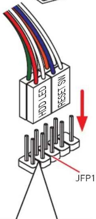
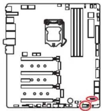
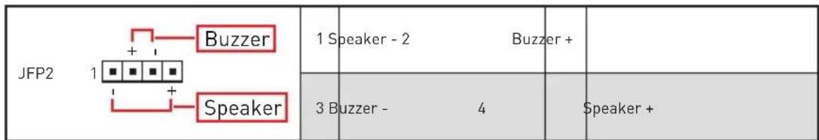
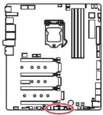
JFP1, JFP2: Front Panel Connectors
These connectors connect to the switches and LEDs on the front panel.
JAUD1: Front Audio Connector
This connector allows you to connect audio jacks on the front panel.
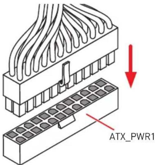
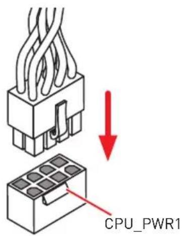
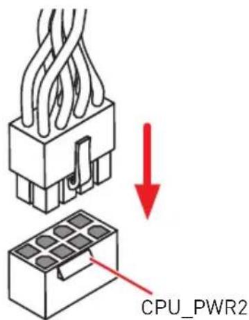
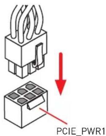
CPU_PWR1~2,ATX_PWR1,PCIE_PWR1:Power Connectors
These connectors allow you to connect an ATX power supply.
| CPU_PWR1/ CPU_PWR2 | |||
| 1 Ground 5 | +12V | ||
| 2 Ground 6 | +12V | ||
| 3 Ground 7 | +12V | ||
| 4 Ground 8 | +12V | ||
| 12 24 ATX_PWR1 1 13 | 1 +3.3V 13 +3.3V | ||
| 2 +3.3V 14 -12V | |||
| 3 Ground 15 Ground | |||
| 4 +5V 16 PS-ON# | |||
| 5 Ground 17 Ground | |||
| 6 +5V 18 Ground | |||
| 7 Ground 19 Ground | |||
| 8 PWR OK 20 Res | |||
| 9 5VSB 21 +5V | |||
| 10 +12V 22 +5V | |||
| 11 +12V 23 +5V | |||
| 12 +3.3V 24 Ground |
| PCIE_PWR1 | 1 + 1 | 2V 4 Ground | ||
| 2 + 1 | 2V 5 Ground | |||
| 3 + 1 | 2V 6 Ground |

Important
Make sure that all the power cables are securely connected to a proper ATX power supply to ensure stable operation of the motherboard.
OC1: GAME BOOST Knob
This knob allows you to manually select a stage from number 0 (default) to number 11 (extreme) for overclocking the processor. The processor's voltage and frequency will be automatically adjusted after you power on your computer.
Using GAME BOOST Knob
To setup the GAME BOOST knob, take the following steps:
- Set the GAME BOOST knob to hardware mode in BIOS Setup.
- Power off the computer.
- Rotate the GAME BOOST knob to select the overclocking stage as you desire.
| Stage | CPU Frequency (GHz) | ||||||
| i3-8350K i5-8600K i7-8700K i7-8086K i5-9600K i7-9700K i9-9900K | |||||||
| 0 GAME BOOST Disabled | |||||||
| 1 4.1 | 4.2~4.4 4.4 | ~4.8 4.4~5.1 | 4.4~4.7 4.7~5.0 | 4.8~4.8~5 | 1 | ||
| 2 4.2 | 4.3~4.5 4.5 | ~4.9 4.5~5.2 | 4.5~4.8 4.8~5.1 | 4.9~4.9~5 | 2 | ||
| 4 4.3 | 4.4~4.6 4.6 | ~5.0 4.6~5.3 | 4.6~4.9 4.9~5.2 | 5.0~5.0~5 | 3 | ||
| 6 4.4 | 4.5~4.7 4.7 | ~5.1 4.7~5.4 | 4.7~5.0 5.0~5.3 | 5.1~5.4 5.1~5.5 | 4 | ||
| 8 4.5 | 4.6~4.8 4.8 | ~5.2 4.8~5.5 | 4.8~5.1 5.1~5.4 | 5.2~5.2~5 | 5 | ||
| 10 4.6 | 4.7~4.9 4.9 | ~5.3 4.9~5.6 | 4.9~5.2 5.2~5.5 | 5.3~5.3~5 | 6 | ||
| 11 4.7 | 4.8~5.0 5.0 | ~5.4 5.0~5.7 | 5.0~5.3 5.3~5.6 | 5.4~5.4~5 | 7 | ||
- Power on and then GAME BOOST will automatically overclock processor depending on the stage you selected.
To disable GAME BOOST:
- Set the GAME BOOST knob to HW mode in BIOS Setup.
- Power off the computer.
- Rotate the GAME BOOST knob to 0 and then power on. The configuration parameters will be returned to default values.
Important
When enabling GAME BOOST mode, it is recommended to use liquid CPU cooler with dual fan radiator for better cooling and performance.
You can also control the GAME BOOST function in BIOS Setup or with MSI DRAGON CENTER software.
In order to optimize performance and improve system stability, when you activate the GAME BOOST function, please leave the settings in the BIOS > OC menu unchanged.
The success of overclocking depends on the components of your computer.
We do not guarantee the GAME BOOST overclocking range or the damages/risks caused by overclocking behavior.
MSI components are recommended for better compatibility when using GAME BOOST function.
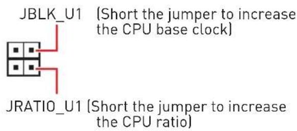
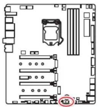
JBLK_U1, JRATIO_U1: Base clock Plus, Ratio Plus connectors
You can use these connectors to connect the external buttons. Press the button connecting to JBLK_U1 to increase the CPU base clock or press the button connecting to JRATIO_U1 to increase the CPU ratio.

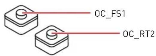
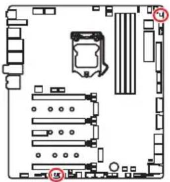
OC_FS1: OC Force Enter BIOS Button
When you press this button, the system will be forced into BIOS without showing the OC_FAIL message.
OC_RT2: OC Retry Button
When you press and hold this button, the system will keep retrying OC items until it boot up successfully.
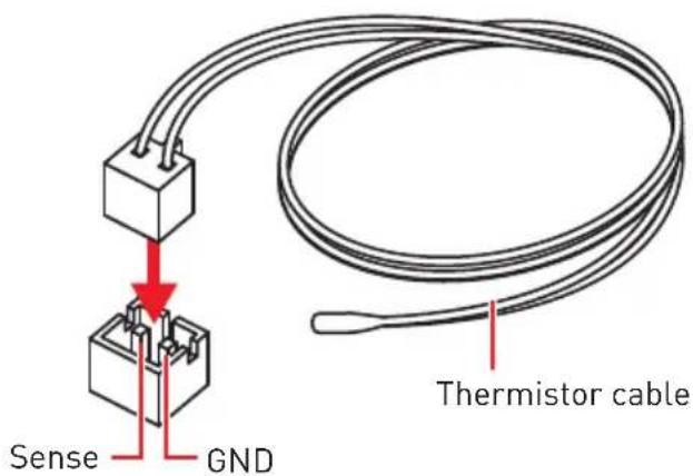
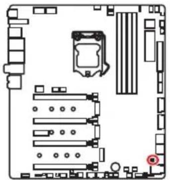
T_SEN1~2: Thermal Sensor Connectors
These connectors allow you to connect the thermistor cable and use it to monitor the temperature of the detection point.
JSLOW1: Slow Mode Booting Jumper
This jumper is used for LN2 cooling solution, that provides the extreme overclocking conditions, to boot at a stable processor frequency and to prevent the system from crashing.

Normal
(default)

Enabled
(Pleases enable this jumper during BIOS POST.)

Important
Users will try extreme low temperature (must be higher than -124 degrees to prevent Debug Code 00) overclocking at their own risks.
The overlapping results will vary according to the CPU version.
Please don't set to Enabled when the system is powered off or can't be started.
CPU_FAN1, PUMP_FAN1, SYS_FAN1~8: Fan Connectors
Fan connectors can be classified as PWM (Pulse Width Modulation) Mode or DC Mode. PWM Mode fan connectors provide constant 12V output and adjust fan speed with speed control signal. DC Mode fan connectors control fan speed by changing voltage. This motherboard can automatically detect PWM and DC mode. However, you can follow the instruction below to adjust the fan connector to PWM or DC Mode manually.
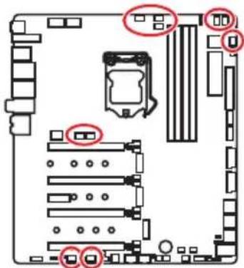

CPU_FAN1/PUMP_FAN1

SYS_FAN1-4 SYS_FAN5-8

You can switch between PWM mode and DC mode and adjust fan speed in BIOS > HARDWARE MONITOR.
Select PWM mode or DC mode
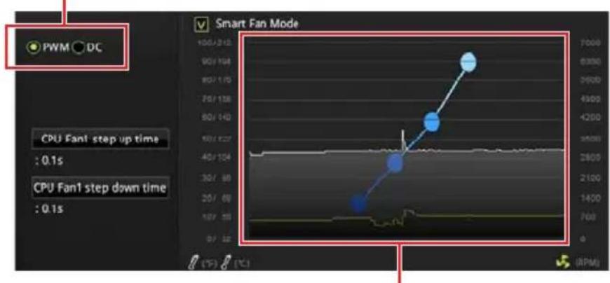
There are gradient points of the fan speed that allow you to adjust fan speed in relation to CPU temperature.

Important
Make sure fans are working properly after switching the PWM/ DC mode.
Pin definition of fan connectors
| PWM Mode pin definition | |||
| 1 G | round 2 +12V | ||
| 3 S | sense 4 Speed | Control | Signal |
| DC Mode pin definition | |||
| 1 G | Ground 2 Voltage | Control | |
| 3 S | Sense 4 NC | ||
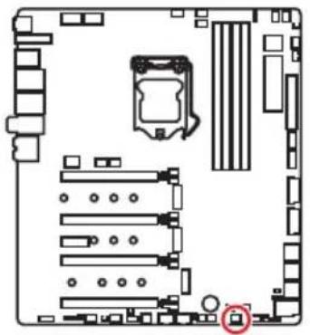
W_FLOW1: Water Flow Meter Connector
This connector allows you to connect a water flow meter to monitor the flow rate of your liquid cooling system.
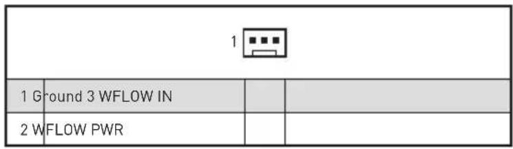
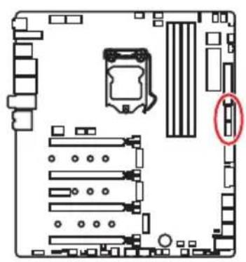
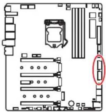
JUSB1~2: USB 3.1 Gen2 Type-C Connectors
These connectors allow you to connect USB 3.1 Gen2 Type-C connectors on the front panel. The connector possesses a foolproof design. When you connect the cable, be sure to connect it with the corresponding orientation.

JUSB3~4: USB 3.1 Gen1 Connectors
These connectors allow you to connect USB 3.1 Gen1 ports on the front panel.
| 10 1 1 20 | |||
| 1 Power 11 USB2.0+ | |||
| 2 USB3_RX_DN 12 USB2.0- | |||
| 3 USB3_RX_DP 13 Ground | |||
| 4 Ground 14 USB3_TX_C_DP | |||
| 5 | USB3_TX_C_DN | 15 | USB3_TX_C_DN |
| 6 | USB3_TX_C_DP | 16 | Ground |
| 7 Ground 17 USB3_RX_DP | |||
| 8 | USB2.0- | 18 | USB3_RX_DN |
| 9 | USB2.0+ | 19 | Power |
| 10 | NC | 20 | No Pin |

Important
Note that the Power and Ground pins must be connected correctly to avoid possible damage.
Charger Port
The JUSB4 connector is a charger port which can increase USB power output for fast charging your smartphone or USB-powered devices. The Charger Port is hardware controlled by motherboard chip, it can still charge your device in suspend, hibernate state or even shutdown states. However, when you boot the computer into Windows® you will need to install the MSI DRAGON CENTER software to turn ON/OFF the Charging mode.

Important
When the Charging mode is enabled, the Charger Port data syncing will be disabled.
JUSB5~6: USB 2.0 Connectors
| 2 10 1 9 | |||
| 1 VCC 2 VCC | |||
| 3 USB0-4 USB1- | |||
| 5 USB0+6 USB1+ | |||
| 7 Ground 8 Ground | |||
| 9 No Pin 10 NC | |||

Important
Note that the VCC and Ground pins must be connected correctly to avoid possible damage.
In order to recharge your iPad,iPhone and iPod through USB ports, please install MSI DRAGON CENTER utility.
Connecting USB Xpander (optional)
The USB Xpander is used to expand a single USB 2.0 connector to 4 connectors. Use the USB Xpander Cable to connect the expansion board and the motherboard as shown below.

POWER1, RESET1: Power Button, Reset Button
The Power / Reset button allows you to power on / reset the computer.
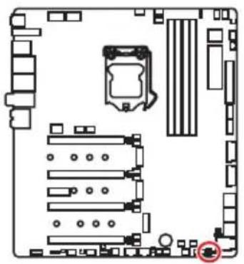
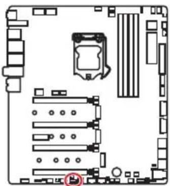
JBAT1: Clear CMOS (Reset BIOS) Jumper
There is CMOS memory onboard that is external powered from a battery located on the motherboard to save system configuration data. If you want to clear the system configuration, set the jumper to clear the CMOS memory.
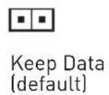
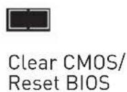
Resetting BIOS to default values
- Power off the computer and unplug the power cord
- Use a jumper cap to short JBAT1 for about 5-10 seconds.
- Remove the jumper cap from JBAT1.
- Plug the power cord and power on the computer.
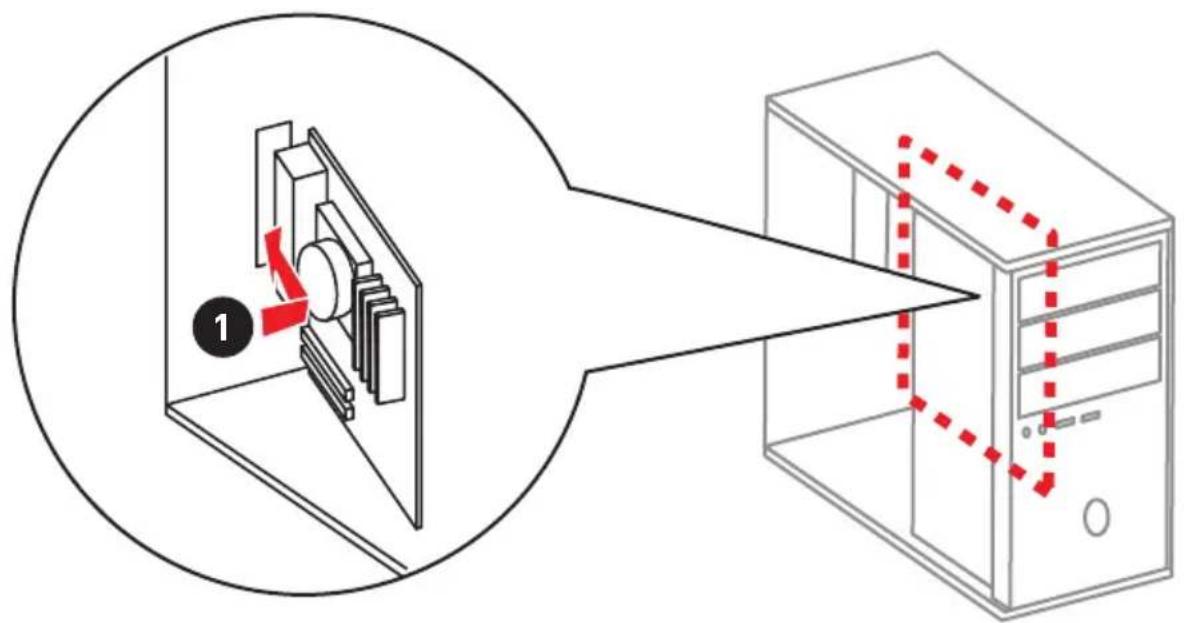
JCI1: Chassis Intrusion Connector
This connector allows you to connect the chassis intrusion switch cable.

Normal (default)

Trigger the chassis intrusion event
Using chassis intrusion detector
- Connect the JCI1 connector to the chassis intrusion switch/ sensor on the chassis.
- Close the chassis cover.
- Go to BIOS > SETTINGS > Security > Chassis Intrusion Configuration.
- Set Chassis Intrusion to Enabled.
- Press F10 to save and exit and then press the Enter key to select Yes.
- Once the chassis cover is opened again, a warning message will be displayed on screen when the computer is turned on.
Resetting the chassis intrusion warning
- Go to BIOS > SETTINGS > Security > Chassis Intrusion Configuration.
- Set Chassis Intrusion to Reset.
- Press F10 to save and exit and then press the Enter key to select Yes.
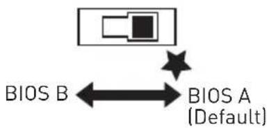
BIOS_SW1: Multi-BIOS Switch
This motherboard has two built-in BIOS ROMs. If one is crashed, you can shift to the other for booting by sliding the switch.
Recovering BIOS
When BIOS updating fails or causes the computer non-bootable, you can recover the failed BIOS by the steps below. Before recovering, please download the latest BIOS file that matches your motherboard model from MSI website. And then save the BIOS file to the root of the USB flash drive.
- Power off the computer.
- Switch to the normal BIOS ROM with Multi-BIOS switch.
- Insert the USB flash drive into the computer.
- Power on the computer and press Del key to enter BIOS setup during POST.
- Select the M-FLASH tab and click on Yes to reboot the system and enter the flash mode.
- Select a BIOS file to perform the BIOS recovering process.
- Switch to the failed BIOS ROM with Multi-BIOS switch, and click on Yes to start recovering BIOS.
- After the recovering process is completed, the system will reboot automatically
Important
Do not use the Multi-BIOS switch when system is booting up.
You can also use the LIVE UPDATE or Flash BIOS Button utility to flash BIOS. Please refer to BIOS section for details.
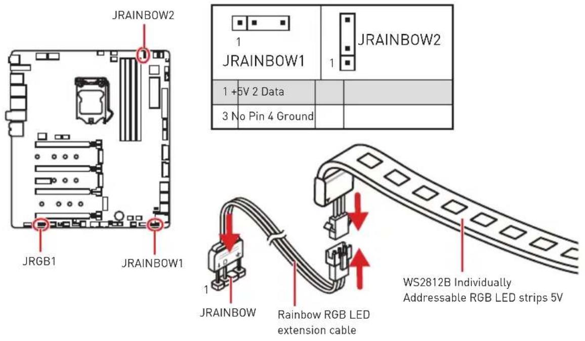
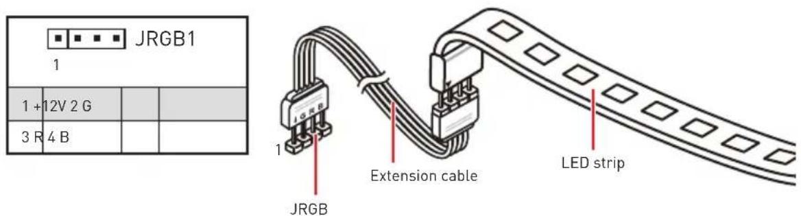
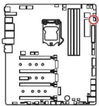
JRGB1, JRAINBOW1~2: RGB LED connectors
The JRGB connector allows you to connect the 5050 RGB LED strips 12V. The JRAINBOW connector allows you to connect the WS2812B Individually Addressable RGB LED strips 5V.

CAUTION
Do not connect the wrong type of LED strips. The JRGB connector and the JRAINBOW connector provide different voltages, and connecting the 5V LED strip to the JRGB connector will result in damage to the LED strip.

Important
The JRGB connector supports up to 2 meters continuous 5050 RGB LED strips (12V/G/R/B) with the maximum power rating of 3A (12V).
The JRAINBOW connector supports up to 75 LEDs WS2812B Individually Addressable RGB LED strips (5V/Data/Ground) with the maximum power rating of 3A (5V). In the case of 20% brightness, the connector supports up to 200 LEDs.
Always turn off the power supply and unplug the power cord from the power outlet before installing or removing the RGB LED strip.
Please use MSI's software to control the extended LED strip.
JCORSAIR1: CORSAIR Connector
The JCORSAIR1 connector allows you to connect the CORSAIR Individually Addressable RGB LED strips 5V or CORSAIR RGB LED fans with the CORSAIR fan hub. Once all items are connected properly, you can control the CORSAIR RGB LED strips and fans with MSI's software.
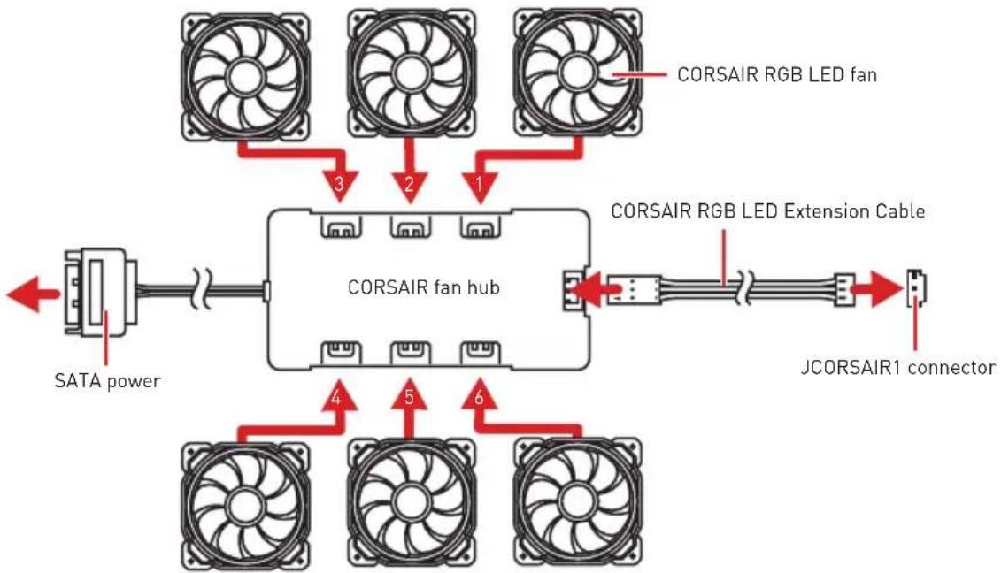
CORSAIR RGB LED Fan Connection

CORSAIR Lighting Node PRO Connection

Important
Fans must start at 1 and continue in series. 1 > 2 > 3 > 4 > 5 > 6 . Any fan not connected in series will break communication and the RGB LED lighting function will not work.
Quantity of RGB LED Fans or RGB LED Lighting PRO strips supported may differ between models. Please refer to the motherboard specification.
CORSAIR RGB LED Fan and CORSAIR Lighting Node PRO can't be used at the same time.
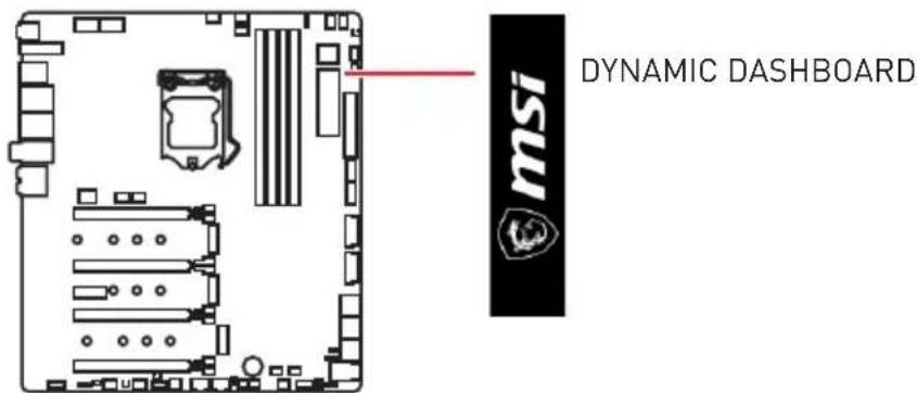
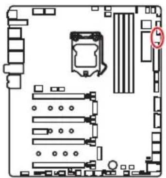
DYNAMIC DASHBOARD
The DYNAMIC DASHBOARD can be used to display system information, CPU temperature, CPU speed, BIOS flash status and error message. You can use MSI's software to configure and customize the DYNAMIC DASHBOARD and even upload a .gif animation file.
DYNAMIC DASHBOARD Status Table
| System Status | DYNAMIC DASHBOARD | System Status | DYNAMIC DASHBOARD |
| Power On | msi | Flash BIOS (Finish) | Finished : ) |
| TRUE GAMING | Flash BIOS (Error] | Update Error | |
| CPU is not detected or fail | CPU Error | Fan Speed/ Temperature/ Voltage | 2390 GOODLIKE CPU TEMP |
| DRAM is not detected or fail | DRAM Error | Game Boost | |
| GPU is not detected or fail | VGA Error | CPU/ VGA/ Memory information | <CPU> |
| Enter the OS | GOOD JOB! | <VGA> | |
| S3 (Suspend to RAM) | TAKE A BREAK | <Memory> | |
| S4/S5 (Sus-pend to Disk/Shutdown) | GOODBYE | User proΩle | 256*64px .gif |
| Flash BIOS (Update) | Updating... |

For information on configuration and customization DYNAMIC DASHBOARD, please refer to the MSI's website.
Onboard LEDs
EZ Debug LED
These LEDs indicate the debug status of the motherboard.
- CPU - indicates CPU is not detected or fail.
DRAM - indicates DRAM is not detected or fail.
VGA - indicates GPU is not detected or fail. - BOOT - indicates the booting device is not detected or fail.
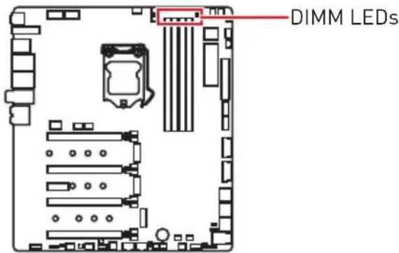
DIMM LEDs
These LED indicate the memory modules are installed.
Fan LEDs
These LEDs indicate the fan control mode.
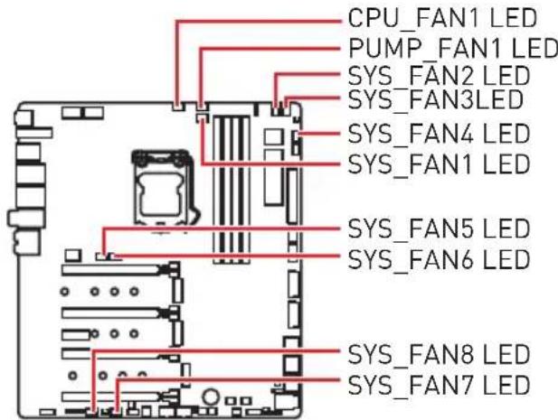
| LED color Fan control mode |
| Red PWM mode |
| White DC mode |
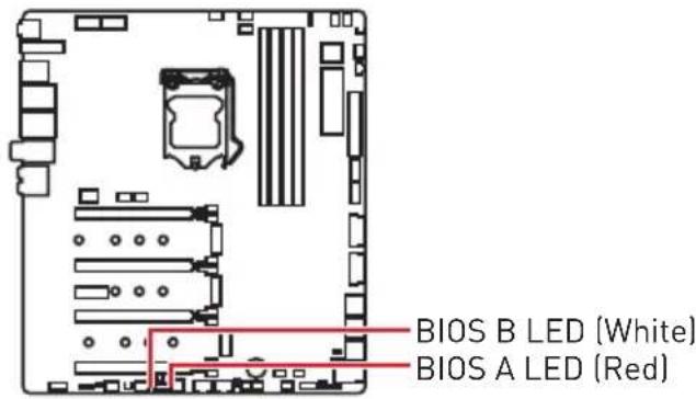
Multi-BIOS LEDs
Multi-BIOS LEDs indicate which BIOS ROM is in operation.
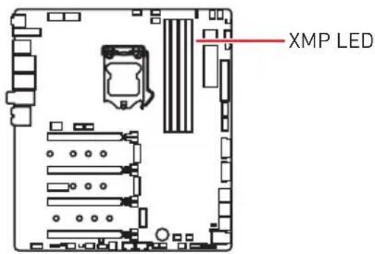
XMPLED
This LED indicates the XMP (Extreme Memory Profile) mode is enabled.
JPWRLED1: LED power input
This connector is used by retailers to demonstrate onboard LED light effects.

CPU Power LED
This LED indicates that the 8-pin CPU power connectors (CPU_PWR1 and CPU_PWR2) are only connected to the 4-pin power connector.

When the CPU Power LED is lit, your computer may be started, but insufficient power may cause system stability issues.
| LED color CPU power connectors status | |
| Red | CPU_PWR1 CPU_PWR2 |
| CPU_PWR1 CPU_PWR2 | |
| CPU_PWR1 CPU_PWR2 | |
| Off | CPU_PWR1 CPU_PWR2 |
| CPU_PWR1 CPU_PWR2 | |
| CPU_PWR1 CPU_PWR2 | |
| CPU_PWR1 CPU_PWR2 | |
| CPU_PWR1 CPU_PWR2 | |
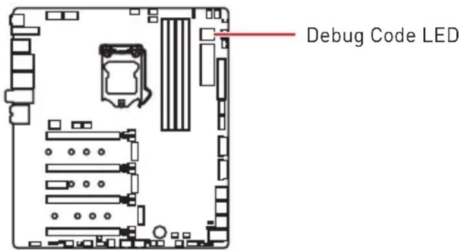
Debug Code LED
The Debug Code LED displays progress and error codes during and after POST. Refer to the Debug Code LED table for details.
Hexadecimal Character Table
| Hexadecimal 0 | 1 2 | 3 4 5 | 6 7 | 8 9 A | B C | D E F | ||||||||
| Debug Code LED display | 0 | 12 | 3456 | 789ABCDEF |
Boot Phases
Security (SEC) - initial low-level initialization
Pre-EFI Initialization (PEI) - memory initialization
Driver Execution Environment (DXE) - main hardware initialization
Boot Device Selection (BDS) - system setup, pre-OS user interface & selecting a bootable device (CD/DVD, HDD, USB, Network, Shell, ...)
Debug Code LED Table
SEC Progress Codes
| 01 Power on. Reset type detection (soft/hard) |
| 02 AP initialization before microcode loading |
| 03 System Agent initialization before microcode loading |
| 04 PCH Initialization before microcode loading |
| 06 Micro code loading |
| 07 AP Initialization after microcode loading |
| 08 System Agent initialization after microcode loading |
| 09 PCH Initialization after microcode loading |
| 0B Cache Initialization |
SEC Error Codes
| 0C - 0D Reserved for future AMI SEC error codes |
| 0E Microcode not found |
| 0F Microcode not loaded |
PEI Progress Codes
| 10 PEI Core is started | |
| 11 Pre-memory CPU initialization is started | |
| 12 - 14 Pre-memory CPU initialization (CPU module specific) | |
| 15 Pre-memory System Agent initialization is started | |
| 16 - 18 Pre-Memory System Agent initialization (System Agent module specific) | |
| 19 Pre-memory PCH initialization is started | |
| 1A - 1C Pre-memory PCH initialization (PCH module specific) | |
| 2B Memory initialization. Serial Presence Detect (SPD) data reading | |
| 2C Memory initialization. Memory presence detection | |
| 2D Memory initialization. Programming memory timing information | |
| 2E Memory initialization. Configuring memory | |
| 2F Memory initialization (other) | |
| 31 Memory Installed | |
| 32 CPU post-memory initialization is started | |
| 33 CPU post-memory initialization. Cache initialization | |
| 34 | CPU post-memory initialization. Application Processor(s) [AP] initialization |
| 35 CPU post-memory initialization. Boot Strap Processor (BSP) selection | |
| 36 | CPU post-memory initialization. System Management Mode (SMM) initialization |
| 37 Post-Memory System Agent initialization is started | |
| 38 - 3A Post-Memory System Agent initialization (System Agent module specific) | |
| 3B Post-Memory PCH initialization is started | |
| 3C - 3E Post-Memory PCH initialization (PCH module specific) | |
| 4F DXE IPL is started |
PEI Error Codes
| 50 | Memory initialization error. Invalid memory type or incompatible memory speed |
| 51 Memory initialization error. SPD reading has failed | |
| 52 | Memory initialization error. Invalid memory size or memory modules do not match |
| 53 Memory initialization error. No usable memory detected | |
| 54 Unspecified memory initialization error | |
| 55 Memory not installed | |
| 56 Invalid | CPU type or Speed |
| 57 CPU mismatch | |
| 58 CPU self test failed or possible CPU cache error | |
| 59 CPU micro-code is not found or micro-code update is failed | |
| 5A Internal CPU error | |
| 5B Reset PPI is not available | |
| 5C - 5F Reserved for future AMI error codes | |
DXE Progress Codes
| 60 DXE Core is started |
| 61 NVRAM initialization |
| 62 Installation of the PCH Runtime Services |
| 63 CPU DXE initialization is started |
| 64 - 67 CPU U DXE initialization (CPU module specific) |
| 68 PCI host bridge initialization |
| 69 System Agent DXE initialization is started |
| 6A System Agent DXE SMM initialization is started |
| 6B - 6F System Agent DXE initialization (System Agent module specific) |
| 70 PCH DXE initialization is started |
| 71 PCH DXE SMM initialization is started |
| 72 PCH devices initialization |
| 73 - 77 PCH DXE Initialization (PCH module specific) |
| 78 ACPI module initialization |
| 79 CSM initialization |
| 7A - 7F Reserved for future AMI DXE codes |
| 90 Boot Device Selection (BDS) phase is started |
| 91 Driver connecting is started |
| 92 PCI Bus initialization is started |
| 93 PCI Bus Hot Plug Controller Initialization |
| 94 PCI Bus Enumeration 32 |
| 95 PCI Bus Request Resources |
| 96 PCI Bus Assign Resources |
| 97 Console Output devices connect |
| 98 Console input devices connect |
| 99 Super ID Initialization |
| 9A USB initialization is started |
| 9B USB Reset |
| 9C USB Detect |
| 9D USB Enable |
| 9E -9F Reserved for future AMI codes |
| A0 IDE initialization is started |
| A1 IDE Reset |
| A2 IDE Detect |
| A3 IDE Enable |
| A4 SCSI initialization is started |
| A5 SCSI Reset |
| A6 SCSI Detect |
| A7 SCSI Enable |
| A8 Setup Verifying Password |
| A9 Start of Setup |
| AB Setup Input Wait |
| AD Ready To Boot event |
| AE Legacy Boot event |
| AF Exit Boot Services event |
| B0 Runtime Set Virtual Address MAP Begin |
| B1 Runtime Set Virtual Address MAP End |
| B2 Legacy Option ROM Initialization |
| B3 System Reset |
| B4 USB hot plug |
| B5 PCI bus hot plug |
| B6 Clean-up of NVRAM |
| B7 Configuration Reset (reset of NVRAM settings) |
| B8 - BF Reserved for future AMI codes |
DXE Error Codes
| D0 CPU in | tialization error |
| D1 System | Agent initialization error |
| D2 PCH in | tialization error |
| D3 Some of the Architectural Protocols are not available | |
| D4 PCI resource allocation error. Out of Resources | |
| D5 No Space for Legacy Option ROM | |
| D6 No Console Output Devices are found | |
| D7 No Console Input Devices are found | |
| D8 Invalid password | |
| D9 Error loading Boot Option (LoadImage returned error) | |
| DA Boot Option is failed (StartImage returned error) | |
| DB Flash update is failed | |
DC Reset protocol is not available
S3 Resume Progress Codes
| E0 S3 Resume | ume is stared (S3 Resume PPI is called by the DXE IPL) |
| E1 S3 Boot | Script execution |
| E2 Video repost | |
| E3 OS S3 wake vector call | |
| E4 - E7 Reserved for future AMI progress codes | |
S3Resume Error Codes
| E8 S3 Resume | ume Failed |
| E9 S3 Resume | ume PPI not Found |
| EA S3 Resume | ume Boot Script Error |
| EB S3 OS | Wake Error |
| EC - EF Reserved for future AMI error codes | |
Recovery Progress Codes
| F0 Recovery condition triggered by firmware (Auto recovery) |
| F1 Recovery condition triggered by user (Forced recovery) |
| F2 Recovery process started |
| F3 Recovery firmware image is found |
| F4 Recovery firmware image is loaded |
| F5 - F7 Reserved for future AMI progress codes |
Recovery Error Codes
| F8 Recovery PPI is not available |
| F9 Recovery capsule is not found |
| FA Invalid recovery capsule |
| FB - FF Reserved for future AMI error codes |
ACPI States Codes
The following codes appear after booting and the operating system into ACPI modes.
| 01 System | is entering S1 sleep state |
| 02 System | is entering S2 sleep state |
| 03 System | is entering S3 sleep state |
| 04 System | is entering S4 sleep state |
| 05 System | is entering S5 sleep state |
| 10 System | is waking up from the S1 sleep state |
| 20 System | is waking up from the S2 sleep state |
| 30 System | is waking up from the S3 sleep state |
| 40 System | is waking up from the S4 sleep state |
| AC | System has transitioned into ACPI mode. Interrupt controller is in PIC mode. |
| AA | System has transitioned into ACPI mode. Interrupt controller is in APIC mode. |
CPU Temperature
| 00 - 99 | Displays current CPU temperature after the system has fully booted into the OS. |
Installing OS, Drivers & Utilities
Please download and update the latest utilities and drivers at www.msi.com
Installing Windows® 10
- Power on the computer.
- Insert the Windows® 10 installation disc/USB into your computer.
- Press the Restart button on the computer case.
- Press F11 key during the computer POST (Power-On Self Test) to get into Boot Menu.
- Select the Windows 10 installation disc/USB from the Boot Menu.
- Press any key when screen shows Press any key to boot from CD or DVD... message.
- Follow the instructions on the screen to install Windows 10.
Installing Drivers
- Start up your computer in Windows® 10.
- Insert MSI^® Driver Disc into your optical drive.
- Click the Select to choose what happens with this disc pop-up notification, then select Run DVDSetup.exe to open the installer. If you turn off the AutoPlay feature from the Windows Control Panel, you can still manually execute the DVDSetup.exe from the root path of the MSI Driver Disc.
- The installer will find and list all necessary drivers in the Drivers/Software tab.
- Click the Install button in the lower-right corner of the window.
- The drivers installation will then be in progress, after it has finished it will prompt you to restart.
- Click OK button to finish.
- Restart your computer.
Installing Utilities
Before you install utilities, you must complete drivers installation.
- Open the installer as described above.
- Click the Utilities tab.
- Select the utilities you want to install.
- Click the Install button in the lower-right corner of the window.
- The utilities installation will then be in progress, after it has finished it will prompt you to restart.
- Click OK button to finish.
- Restart your computer.
BIOS Setup
The default settings offer the optimal performance for system stability in normal conditions. You should always keep the default settings to avoid possible system damage or failure booting unless you are familiar with BIOS.
Important
BIOS items are continuously update for better system performance. Therefore, the description may be slightly different from the latest BIOS and should be for reference only. You could also refer to the HELP information panel for BIOS item description.
The pictures in this chapter are for reference only and may vary from the product you purchased.
Entering BIOS Setup
Please refer the following methods to enter BIOS setup.
- Press Delete key, when the Press DEL key to enter Setup Menu, F11 to enter Boot Menu message appears on the screen during the boot process.
- In MSI Dragon Center application, click on GO2BIOS button and choose OK. The system will reboot and enter BIOS setup directly.
Function key
F1: General Help
F2: Add/ Remove a favorite item
F3: Enter Favorites menu
F4: Enter CPU Specifications menu
F5: Enter Memory-Z menu
F6: Load optimized defaults
F7: Switch between Advanced mode and EZ mode
F8: Load Overclocking Profile
F9: Save Overclocking Profile
F10: Save Change and Reset*
F12: Take a screenshot and save it to USB flash drive (FAT/ FAT32 format only).
Ctrl+F: Enter Search page
- When you press F10, a confirmation window appears and it provides the modification information. Select between Yes or No to confirm your choice.
Resetting BIOS
You might need to restore the default BIOS setting to solve certain problems. There are several ways to reset BIOS:
- Go to BIOS and press F6 to load optimized defaults.
- Short the Clear CMOS jumper on the motherboard.

Be sure the computer is off before clearing CMOS data. Please refer to the Clear CMOS jumper section for resetting BIOS.
Updating BIOS
Updating BIOS with M-FLASH
Before updating:
Please download the latest BIOS file that matches your motherboard model from MSI website. And then save the BIOS file into the USB flash drive.
Updating BIOS:
- Insert the USB flash drive that contains the update file into the USB port.
-
Please refer the following methods to enter flash mode.
-
Reboot and press Ctrl + F5 key during POST and click on Yes to reboot the system.
-
Reboot and press Del key during POST to enter BIOS. Click the M-FLASH button and click on Yes to reboot the system.
-
Select a BIOS file to perform the BIOS update process.
- When prompted, switch to the target BIOS ROM with Multi-BIOS switch, and click on Yes to start recovering BIOS.
- After the flashing process is 100% completed, the system will reboot automatically.
Updating the BIOS with MSI DRAGON CENTER
Before updating:
Make sure the LAN driver is already installed and the Internet connection is set properly.
Updating BIOS:
- Install and launch MSI DRAGON CENTER.
- Select BIOS Update.
- Click on Scan button.
- Click on Download icon to download and install the latest BIOS file.
- Click Next and choose In Windows mode. And then click Next and Start to start updating BIOS.
- After the flashing process is 100% completed, the system will restart automatically.
Updating BIOS with Flash BIOS Button
Before updating:
Please download the latest BIOS file that matches your motherboard model from MSI® website and rename the BIOS file to MSI.ROM. And then, save the MSI.ROM file to the root of USB flash drive.
! Important
Only the FAT32 format USB flash drive supports updating BIOS by Flash BIOS.
- Connect power supply to CPU_PWR1 and ATX_PWR1. (No other components are necessary but power supply.)
- Plug the USB flash drive that contains the MSI.ROM file into the Flash BIOS port on rear I/O panel.
- Press the Flash BIOS Button to flash BIOS, and the LED on the Flash BIOS Button starts flashing.
- After the flashing BIOS process is 100% completed, the LED would be off simultaneously.
EZ Mode
At EZ mode, it provides the basic system information and allows you to configure the basic setting. To configure the advanced BIOS settings, please enter the Advanced Mode by pressing the Setup Mode switch or F7 function key.
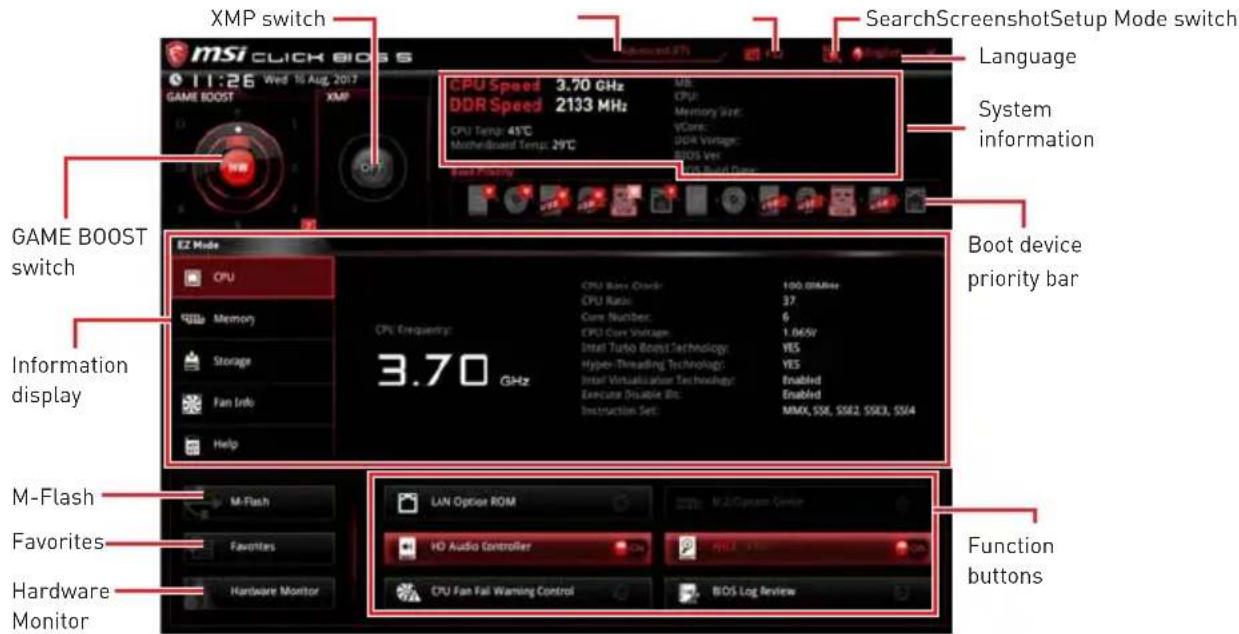
- GAME BOOST switch - click on the center button to switch GAME BOOST control between software (SW) and hardware (HW). The inner circle represents the current stage of hardware GAME BOOST and the outer circle stands for software. You can read the CPU frequency of each GAME BOOST stage by clicking on the icon at right-bottom corner.
Important
Please don't make any changes in OC menu and don't load defaults to keep the optimal performance and system stability after activating the GAME BOOST function.
-
XMP switch - click on the inner circle to enable/ disable the X.M.P. [Extreme Memory Profile]. Switch the outer circle to select the X.M.P. profile. This switch will only be available if the X.M.P. supported memory module is installed.
-
Setup Mode switch - press this tab or the F7 key to switch between Advanced mode and EZ mode.
-
Screenshot - click on this tab or the F12 key to take a screenshot and save it to USB flash drive (FAT/ FAT32 format only).
-
Search - click on this tab or the Ctrl+F keys and the search page will show. It allows you to search by BIOS item name, enter the item name to find the item listing. Move the mouse over a blank space and right click the mouse to exit search page.
Important
In search page, only the F6, F10 and F12 function keys are available.
-
Language - allows you to select the language of BIOS setup.
-
System information - shows the CPU/ DDR speed, CPU/ MB temperature, MB/ CPU type, memory size, CPU/ DDR voltage, BIOS version and build date.
-
Boot device priority bar - you can move the device icons to change the boot priority. The boot priority from high to low is left to right.
-
Information display - click on the CPU, Memory, Storage, Fan Info and Help buttons on left side to display related information.
-
Function buttons - enable or disable the LAN Option ROM, M.2/Optane Genie, HD audio controller, AHCI, RAID, CPU Fan Fail Warning Control and BIOS Log Review by clicking on their respective button.
-
M-Flash - click on this button to display the M-Flash menu that provides the way to update BIOS with a USB flash drive.
-
Hardware Monitor - click on this button to display the Hardware Monitor menu that allows you to manually control the fan speed by percentage.
-
Favorites - press the Favorites tab or the F3 key to enter Favorites menu. It allows you to create personal BIOS menu where you can save and access favorite/ frequently-used BIOS setting items.
-
Default HomePage - allows you to select a BIOS menu (e.g. SETTINGS, OC...,etc) as the BIOS home page.
-
Favorite1~5 - allows you to add the frequently-used/ favorite BIOS setting items in one page.
To add a BIOS item to a favorite page (Favorite 1~5) -
Move the mouse over a BIOS item not only on BIOS menu but also on search page.
- Right-click or press F2 key.
- Choose a favorite page and click on OK.
To delete a BIOS item from favorite page
- Move the mouse over a BIOS item on favorite page (Favorite 1~5)
- Right-click or press F2 key.
- Choose Delete and click on OK.
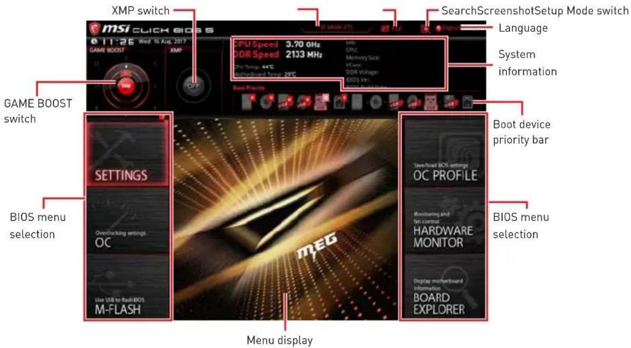
Advanced Mode
Press Setup Mode switch or F7 function key can switch between EZ Mode and Advanced Mode in BIOS setup.
-
GAME BOOST switch/ XMP switch/ Setup Mode switch/ Screenshot/ Language/ System information/ Boot device priority bar - please refer to the descriptions of EZ Mode Overview section.
-
BIOS menu selection - the following options are available:
-
SETTINGS - allows you to specify the parameters for chipset and boot devices.
- OC - allows you to adjust the frequency and voltage. Increasing the frequency may get better performance.
- M-FLASH - provides the way to update BIOS with a USB flash drive.
- OC PROFILE - allows you to manage overclocking profiles.
- HARDWARE MONITOR - allows you to set the speeds of fans and monitor voltages of system.
-
BOARD EXPLORER - provides the information of installed devices on this motherboard.
-
Menu display - provides BIOS setting items and information to be configured.
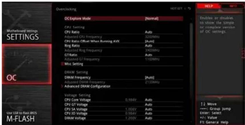
OC Menu
This menu is for advanced users who want to overclock the motherboard.

Important
Overclocking your PC manually is only recommended for advanced users.
Overclocking is not guaranteed, and if done improperly, it could void your warranty or severely damage your hardware.
If you are unfamiliar with overclocking, we advise you to use GAME BOOST function for easy overclocking.
OC Explore Mode [Expert]
Enables or disables to show the normal or expert version of OC settings.
[Normal] Provides the regular OC settings in BIOS setup.
[Expert] Provides the advanced OC settings for OC expert to configure in BIOS setup.
Note: We use * as the symbol for the OC settings of Expert mode.
CPU Ratio Apply Mode [All Core]*
Sets applied mode for CPU ratio. This item only appears when a CPU that supports Turbo Boost is installed.
[All Core] Enables the CPU Ratio. All CPU cores will run the same CPU ratio that be set in CPU Ratio.
[Per Core] Enables the Core XX of X xxxx MHz. Sets each CPU core ratio separately.
[Turbo Ratio] Enables the X-Core Ration Limit. This option only appears when a CPU that supports this function is installed.
X-Core Ratio Limit [Auto]*
Allows you to set the CPU ratios for different number of active cores. These items only appear when CPU Ratio Apply Mode set to Turbo Ratio.
Adjusted CPU Frequency
Shows the adjusted CPU frequency. Read-only.
Core XX of X xxxx MHz [Auto]*
Allows you to set the CPU ratios for different number of active cores. These items only appear when CPU Ratio Apply Mode set to Per Core.
CPU Ratio Offset When Running AVX [Auto]
Sets a offset value to lower the CPU core ratio. It could be helpful for heat dissipation when running AVX instruction set. If set to Auto, BIOS will configure this setting automatically. This item appears when the installed CPU supports this function.
Ring Ratio [Auto]
- Sets the ring ratio. The valid value range depends on the installed CPU.
Adjusted Ring Frequency
Shows the adjusted Ring frequency. Read-only.
GT Ratio [Auto]
Sets the integrated graphics ratio. The valid value range depends on the installed CPU.
Adjusted GT Frequency
Shows the adjusted integrated graphics frequency. Read-only.
Misc Setting*
Press Enter, + or - key to open or close the following 3 items related to CPU features.
EIST [Enabled]*
Enables or disables the Enhanced Intel® SpeedStep Technology.
[Enabled] Enables the EIST to adjust CPU voltage and core frequency dynamically. It can decrease average power consumption and average heat production.
[Disabled] Disables EIST.
▶Intel Turbo Boost [Enabled]*
Enables or disables the Intel® Turbo Boost. This item appears when the installed CPU supports this function.
[Enabled] Enables this function to boost CPU performance automatically above rated speciΩcations when system request the highest performance state.
[Disabled] Disables this function.
Extreme Memory Profile (X.M.P.) [Disabled]
X.M.P. (Extreme Memory Profile) is the overclocking technology by memory module. Please enable XMP or select a profile of memory module for overclocking the memory. This item will be available when the memory modules that support X.M.P. is installed.
DRAM Reference Clock [Auto]*
Sets the DRAM reference clock. The valid value range depends on the installed CPU. This item appears when a CPU that supports this adjustment is installed.
DRAM Frequency [Auto]
Sets the DRAM frequency. Please note the overclocking behavior is not guaranteed.
Adjusted DRAM Frequency
Shows the adjusted DRAM frequency. Read-only.
Memory Try It ! [Disabled]
It improve memory compatibility or performance by choosing optimized memory preset.
DRAM Timing Mode [Link]
Selects the memory timing mode.
[Link] Allows user to configure the DRAM timing for all memory channel.
[UnLink] Allows user to configure the DRAM timing for respective memory channel.
Advanced DRAM Configuration
Press Enter to enter the sub-menu. User can set the memory timing for each/ all memory channel. The system may become unstable or un-bootable after changing memory timing. If it occurs, please clear the CMOS data and restore the default settings. (Refer to the Clear CMOS jumper/ button section to clear the CMOS data, and enter the BIOS to load the default settings.)
Memory Fast Boot [Auto]*
Enables or disables the initiation and training for memory every booting.
[Auto] The setting will be configured automatically by BIOS.
[Enabled] System will completely keep the archives of first initiation and training for memory. So the memory will not be initialed and trained when booting to accelerate the system booting time.
[Disabled] The memory will be initiated and trained every booting.
CPU Voltages control [Auto]
These options allow you to set the voltages related to CPU. If set to Auto, BIOS will set these voltages automatically or you can set it manually.
DRAM Voltages control [Auto]
These options allow you to set the voltages related to memory. If set to Auto, BIOS will set these voltages automatically or you can set it manually.
CPU Memory Changed Detect [Enabled]*
- Enables or disables the system to issue a warning message during boot when the CPU is in memory or memory has been replaced.
[Enabled] The system will issue a warning message during boot and then you have to load the default settings for new devices.
[Disabled] Disables this function and keeps the current BIOS settings.
CPU Specifications
Press Enter to enter the sub-menu. This sub-menu displays the information of installed CPU. You can also access this information menu at any time by pressing [F4]. Read only.
CPU Technology Support
Press Enter to enter the sub-menu. The sub-menu shows the key features of installed CPU. Read only.
MEMORY-Z
Press Enter to enter the sub-menu. This sub-menu displays all the settings and timings of installed memory. You can also access this information menu at any time by pressing [F5].
> DIMMA1/A2/B1/B2 Memory SPD
Press Enter to enter the sub-menu. The sub-menu displays the information of installed memory. Read only.
CPU Features
Press Enter to enter the sub-menu.
Hyper-Threading [Enabled]
Intel Hyper-Threading technology treats the multi cores inside the processor as multi logical processors that can execute instructions simultaneously. In this way, the system performance is highly improved. This item appears when the installed CPU supports this technology.
[Enable] Enables Intel Hyper-Threading technology.
[Disabled] Disables this item if the system does not support HT function.
Active Processor Cores Control [All]
Allows you to select the number of active CPU cores.
Limit CPUID Maximum [Disabled]
Enables or disables the extended CPUID value.
[Enabled] BIOS limits the maximum CPUID input value to circumvent boot problems with older operating system that do not support the processor with extended CPUID value.
[Disabled] Use the actual maximum CPUID input value.
Intel Virtualization Tech [Enabled]
Enables or disables Intel Virtualization technology.
[Enabled] Enables Intel Virtualization technology and allows a platform to run multiple operating systems in independent partitions. The system can function as multiple systems virtually.
[Disabled] Disables this function.
Intel VT-D Tech [Disabled]
Enables or disables Intel VT-D (Intel Virtualization for Directed I/O) technology.
Hardware Prefetcher [Enabled]
Enables or disables the hardware prefetcher (MLC Streamer prefetcher).
[Enabled] Allows the hardware prefetcher to automatically pre-fetch data and instructions into L2 cache from memory for tuning the CPU performance.
[Disabled] Disables the hardware prefetcher.
Adjacent Cache Line prefetch [Enabled]
Enables or disables the CPU hardware prefetcher (MLC Spatial prefetcher).
[Enabled] Enables adjacent cache line prefetching for reducing the cache latency time and tuning the performance to the specc application.
[Disabled] Enables the requested cache line only.
CPU AES Instructions [Enabled]
Enables or disables the CPU AES (Advanced Encryption Standard-New
Instructions) support. This item appears when a CPU supports this function.
Intel Adaptive Thermal Monitor [Enabled]
Enables or disables the Intel adaptive thermal monitor function to protect the CPU from overheating.
[Enabled] Throttles down the CPU core clock speed when the CPU is over the adaptive temperature.
[Disabled] Disables this function.
Intel C-State [Auto]
Enables or disables the Intel C-state. C-state is a processor power management technology deΩned by ACPI.
[Auto] This setting will be confgured automatically by BIOS.
[Enabled] Detects the idle state of system and reduce CPU power consumption accordingly.
[Disabled] Disable this function.
C1E Support [Disabled]
Enables or disables the C1E function for power-saving in halt state. This item appears when Intel C-State is enabled.
[Enabled] Enables C1E function to reduce the CPU frequency and voltage for power-saving in halt state.
[Disabled] Disables this function.
Package C State limit [Auto]
This item allows you to select a CPU C-state level for power-saving when system is idle. The options of C-state depend on the installed CPU. This item appears when Intel C-State is enabled.
CFG Lock [Enabled]
Lock or un-lock the MSR 0xE2[15], CFG lock bit.
[Enabled] Locks the CFG lock bit.
[Disabled] Un-locks the CFG lock bit.
Long Duration Power Limit (W) [Auto]
Sets the long duration TDP power limit for CPU in Turbo Boost mode.
Long Duration Maintained (s) [Auto]
Sets the maintaining time for Long duration power Limit(W).
Short Duration Power Limit (W) [Auto]
Sets the short duration TDP power limit for CPU in Turbo Boost mode.
CPU Current Limit (A) [Auto]
Sets maximum current limit of CPU package in Turbo Boost mode. When the current is over the specified value, the CPU will automatically reduce the core frequency for reducing the current.
FCLK Frequency [Auto]
- Sets FCLK frequency. Lower FCLK frequency may help you to set higher base clock frequency.
>DMI Link Speed [Auto]
Sets DMI speed.
SW Guard Extensions (SGX) [Software Control]
Enables or disables Intel SGX.
NOTE
Inhalt
SATA1~6: SATA 6 Gb/s Anschlüsse
JFP1, JFP2: Frontpanel-Anschlüsse
| PCIE_PWR1 | 1 +1 | 2V 4 Ground | ||
| 2 +1 | 2V 5 Ground | |||
| 3 +1 | 2V 6 Ground |

Wichtig
JBLK_U1, JRATIO_U1: Basistakt Plus/ Ratio Plus Anschlüsse
JUSB3~4: USB 3.1 Gen1 Anschlüsse
| 10 1 20 | |||
| 1 Power 11 USB2.0+ | |||
| 2 USB3_RX_DN 12 USB2.0- | |||
| 3 USB3_RX_DP 13 Ground | |||
| 4 Gound 14 USB3_TX_C_DP | |||
| 5 | USB3_TX_C_DN | 15 | USB3_TX_C_DN |
| 6 | USB3_TX_C_DP | 16 | round |
| 7 Gound 17 USB3_RX_DP | |||
| 8 | USB2.0- | 18 | USB3_RX_DN |
| 9 | USB2.0+ | 19 | Power |
| 10 | NC | 20 | No Pin |

Wichtig
JUSB5~6: USB 2.0 Anschlüsse
| 2 10 1 9 | |||
| 1 VCC 2 VCC | |||
| 3 USB0-4 USB1- | |||
| 5 USB0+6 USB1+ | |||
| 7 Ground 8 Ground | |||
| 9 No Pin 10 NC | |||

Wichtig
Adjusted CPU Frequency
Core XX of X xxxx MHz [Auto]*
Adjusted Ring Frequency
Adjusted GT Frequency
DRAM Frequency [Auto]
Adjusted DRAM Frequency
CPU Voltages control [Auto]
DRAM Voltages control [Auto]
CPU Memory Changed Detect [Enabled]*
CPU Technology Support
Intel Virtualization Tech [Enabled]
Intel VT-D Tech [Disabled]
Intel C-State [Auto]
Package C State limit [Auto]
Long Duration Maintained (s) [Auto]
Short Duration Power Limit (W) [Auto]
FCLK Frequency [Auto]
SW Guard Extensions (SGX) [Software Control]
| JFP2 1 Buzzer | 1 S | speaker - 2 | Buzzer + | |
| 3 Buzzer - 4 | Speaker + | |||
| 2 10 1 9 | |||
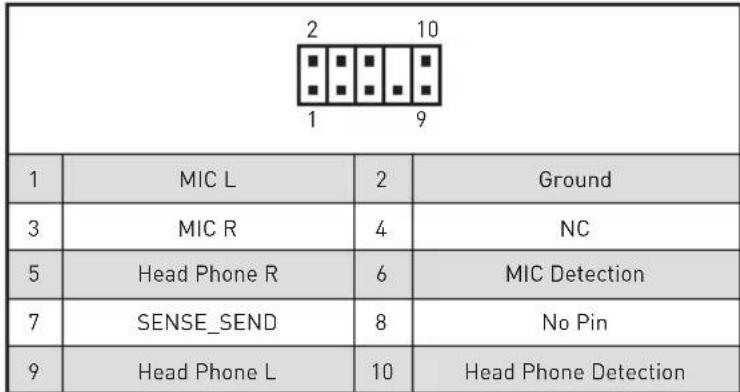
| 1 | MIC L | 2 | Ground |
| 3 | MIC R | 4 | NC |
| 5 | Head Phone R | 6 | MIC Detection |
| 7 | SENSE_SEND | 8 | No Pin |
| 9 | Head Phone L | 10 | Head Phone Detection |
CPU_PWR1~2,ATX_PWR1,PCIE_PWR1:Connecteurs d'alimentation
| 10 1 20 | |||
| 1 Power 11 USB2.0+ | |||
| 2 USB3_RX_DN 12 USB2.0- | |||
| 3 USB3_RX_DP 13 Ground | |||
| 4 Ground 14 | USB3_TX_C_DP | ||
| 5 | USB3_TX_C_DP | 15 | USB3_TX_C_DP |
| 6 | USB3_TX_C_DP | 16 | Ground |
| 7 Ground 17 | USB3_RX_DP | ||
| 8 | USB2.0- | 18 | USB3_RX_DP |
| 9 | USB2.0+ | 19 | Power |
| 10 | NC | 20 | No Pin |

Important
Adjusted CPU Frequency
Core XX of X xxxx MHz [Auto]*
Adjusted Ring Frequency
Adjusted GT Frequency
DRAM Frequency [Auto]
Adjusted DRAM Frequency
CPU Voltages control [Auto]
DRAM Voltages control [Auto]
CPU Memory Changed Detect [Enabled]*
CPU Technology Support
Hyper-Threads [Enabled]
Intel Virtualization Tech [Enabled]
Active ou désactive la technologie Intel Virtualization.
Intel VT-D Tech [Disabled]
Active ou désactive la technologie Intel VT-D (Intel Virtualization for Direct I/O).
Hardware Prefetcher [Enabled]
Active ou désactive le prefetcher matériel (MLC Streamer prefetcher).
Intel C-State [Auto]
Package C State limit [Auto]
Long Duration Maintained (s) [Auto]
Short Duration Power Limit (W) [Auto]
FCLK Frequency [Auto]
SW Guard Extensions (SGX) [Software Control]
Active ou désactive Intel SGX.
NOTE
CodelpkaHne
Be3oNaHoe nCnoJIb3OBaHne npOdyKcIe 3
Texnueckne xapaKTeprncTnki 4
KoMnJIeKT noCTaBKn 11
3aHnra HaneIb NOpTOB BBOda/BbIBOda 12
KomnoentbImatepHckoI IaTbI 16
Texnueckne xapaKtepcntkn pa3bema JCORSAIR1 10
Ta6nua cocToHn HndkaTopa nopTa LAN 12
KoHnurpaun npToB Aynio 12
Realtek Audio Console 13
YcTaHOBka aHTeHH 15
Ipoceccopnbic coket 17
CnotbDIMM 18
PCI_E1~5: CnotbI paCnupenHna PCIe 19
PEGSW1: IpeeknouaTeIb PCIe CeaseFire 20
U2_1:Pa3beM U.2 22
M2_1~3:Pa3beMbI M.2 (KIOU M) 23
Pa3bemblnla3amepa HanpjaKeHHa V-Check Points 25
YcTaHOBka M.2 Xpander-Z 26
SATA1~6:Pa3beMbI SATA 6Γ6/c 27
JFP1, JFP2: Pa3bembl nepednei nahei 29
JAUD1:Pa3bem aydno nepednei nanei 29
CPU_PWR1~2,ATX_PWR1,PCIE_PWR1:Pa3bemblnTaHnra. 30
OC1: Khonka GAME BOOST 31
JBLK_U1, JRATIO_U1: Pa3bem yBeJIuEHHa 6a3OBoY qAcToTbI, Pa3bem yBeJIuEHHa MHOxHtTeJI. 32
OC_FS1:OC KhoNka npHnynteIbHoro BxoDa BBIOS 32
OC_RT2:Pa3bem OC Retry 32
T_SEN1~2:Pa3bEmbl DaTUnKa TeMnepaTpybl 33
JSLOW1:Джампер рекиma MeДлeнHo 3aRpy3kn. 33
CPU_FAN1, PUMP_FAN1, SYS_FAN1~8: Pa3bembl BeHTnlaTopoB 34
W_FLOW1: Pa3bem daTunka ckopoctn noToKa OXnaKdaUoSei KndKoctn.. 35
JUSB1~2:Pa3beMbUSB3.1Gen2Type-C 35
JUSB3-4:Pa3beMbUSB3.1 Gen1 36
JUSB5-6:Pa3beMbUSB2.0 37
POWER1, RESET1: Khonka nitaHn, Khonka nepe3arpy3kn 38
JBAT1:Джампер оочткданнвix CMOS [C6poc BIOS] 38
JCI1:Pa3bEm DaTUnKa OTKpbITnK Kopnyca 39
BIOS_SW1:Переклουатель Multi-BIOS 40
JRGB1,JRAINBOW1\~2:Pa3beMbI RGB LED 41
JCORSAIR1:Pa3bemCORSAIR 42
DYNAMIC DASHBOARD 43
Ta6nua coctoHn DYNAMIC DASHBOARD 43
BcTpoeHbIe HndnKaToPbI 44
Hndkatopbl otlaekn EZ 44
HndkaTopb DIMM 44
HndkaTopbBeHTkaTopa 44
HnndkaTopb Multi-BIOS. 45
HndkaTop XMP 45
JPWRLED1:Инд 45
HndkaTOp nHTaHnI npoceccopa 46
HndkaTOp OTnaOuHbIX KOIOB 47
Ta6nua weecThaundatnpuHbIX CmB0JOB 47
Φa3bl 3arpy3kn. 47
Ta6nua oTnaOuHbIX KOIOB 47
KoDbI coCToHn ACPI 52
Tempepatypa npoueccopa 52
YcTaHOBKa OC,dpaBepOB uYtNlNT 53
YcTaHOBkaWindows 10. 53
UcTaHOBka dpaIbepOB 53
YCTaHOBka yTnIIT 53
HacrpoikaBIOS 54
Bxod B HacTroPoiKnBIOS 54
C6pocBIOS 55
06HOBJIeHneBIOS. 55
Pexum EZ 57
Pexim pa3roHa 59
MeHIOOC 60
B cnlyae, ecnn MaTePNHcKa Pnata He yCTaHOBneHa B KOpnyc, xpaHnte ee B aHTncTaTnueeCKo YnaKOBKe nn Ha aHTncTaTnueeCKOM KObpke.
- Pered BKIOUeHnEM KOMbIOTepa y6eNTecb, YTO BCE BUNTbI KpeJIeHnI IN DpyrHe MeTaJIINueCKNe KOMNoHEtbl Ha MaTePNHcKo INaTe N BHyTpN KOpNyCa HAdExHO 3aΦNKcnpOBaHbl.
He BkIIOuayTe KOMNbIoTeP,ecn c6OpKa He 3aBepweHa.3To MoKeT npNBecTu KOBpeKdEHHO KOMNOHeHTOB,a TaKke TpaBMnpOBaHHo NOLb3OBaTeJRA.
-
Ecnn Bam HuyxHa nOoB Ha IIO6om 3Tane c6opKn KOMnbIOTepa, noXaIyIcTa, o6paTnTeCb K cepTnΦnUPOBaHHOMy KOMNbIOTepHOMy CneuaJIInCTy.
-
Bcerda BbIKIouaTe nHTaHne n OTcoeINHnTe wHyp nHTaHnO T3JIeKTPnueCKo p03ETKn nepey yCTaHOBKO nn ydaJeHNem IIO6Oro KOMNoHErTa KOMNbIoTEpa.
-
CoxpaHnTe 3To pyKOBoDCTBO nIa CnpaBKn.
He donyckaIte Bo3dienCTBna Ha MaTePNHCKayIO NlaTy BbICOKO BlaXHOCTN
-
IpepeTem KaK NODKIOUHTb 6IOK NITAHN KOMNbOTepa K 3JIeKTpUYeCKO p03eTke y6eNTecb, YTO HApPKeHne 3JIeKTPocETn COOTBETCTByeT HaNPJKeHHIO yKa3aHHOMy Ha 6Ioke NITAHN.
-
PacnojaraTe uHyp nHTaHn TaK, uTo6bHa HrO He MoTJn HaCTyNTb JIOJn. He cTaBbTe Ha uHyp nHTaHn HnKaKnx npedMeTOB.
Heo6xOIMO yuHTbBaTb BCE npedocTepeKeHn I npedynpexKdEHHyka3aHHbIe Ha MaTePHNCKo Pnate.
MaTepuHckaIpaTaHe pa6oTaet OJXHBIM 6pa3OM IIN HeBO3MOxHO HanaTbe pa6OBy B COOTBETCTBUN C pyKOBOIDCTBOM IOJIb3OBaTeJI.
-
Matepнская плata полушина повражdenя за падени.
-
MatepeHckaI pIaT a IMeet ABhIe np3HaKn NOBpeKdEHHa.
He xpaHnTe MaTepuHckyo nnAty B MeCtax C TeMpepaTpyoB Bbiue 60^ (140^) TaK KaK 3TO MOKeT PnUBeCTN K ee NOBpeKdEHHIO.
TexHnueckne xapaKTepeNCTnKN
| Пюцeccор | Пюдөржka рюцeccоров Intel® Core™ 9000-ий сери / Intel® Core™ 8-RO поколени / Pentium® Gold / Celeron®對於 COkeTa LGA 1151 * Пожалуоста, образитесь www.intel.com對於 пolyчени до погнітейнійинформачи о COBmecTImoc'tn. |
| Чирсет Intel | ® Z390 |
| Память | • 4х сlotsа памятс DD4 с подөржкоий до 64ГБ* • Пюдөржka DDR4 4600(OC)/ 4533(OC)/ 4500(OC)/ 4400(OC)/ 4300(OC)/ 4266(OC)/ 4200(OC)/ 4133(OC)/ 4000(OC)/ 3866(OC)/ 3733(OC)/ 3600(OC)/ 3466(OC)/ 3400(OC)/ 3333(OC)/ 3300(OC)/ 3200(OC)/ 3000(OC)/2800(OC)/ 2666/ 2400/ 2133 MФ* |
| • Двухсаньая apхитектура • Пюдөржka non-ECC, небуфэрizованнoi памятii • Пюдөржka InteKExtreme Memory Profile (XMP) * Пожалуоста, образитесь www.msi.com對於 пolyчени до погнітейнійинформачи о COBmecTImbIX памятii. | |
| Сlotsы pacширения | • 4х сlotsa PCIe 3.0 x16* • 1x сlotsa PCIe 3.0 x1 *对于我们 podroбосте CM. наст. 19. |
| Пюдөржka Multi-GPU | • Пюдөржka Тхнологи 2-Way NVIDIA® SLITM • Пюдөржka Тхнологи 4-Way AMD® CrossFireTM |
| Пюдөржka NaHОпNTeLEi | Чирсет Intel® Z390 • 6х по对接 SATA 6ГБ/c* • 3х разьема M.2 (Клоч M)* • Разьемы M2_1 и M2_3 подөржИBAJOТ PCIe 3.0 x4 и SATA 6ГБ/c, наcodптели 2242/ 2260/ 2280/ 22110 • Разьем M2_2 подөржИВаERT PCIe 3.0 x4 и SATA 6ГБ/c, наcodптели 2242/ 2260/ 2280 • Р拿出来ngа памятii Intel® OptaneTM • 1x поТ U.2* • Пюдөржka нахолтели PCIe 3.0 x4 NVMe * Р拿出来ngа M.2_2, поТы U.2 и SATA Inc polny lo polocу пponускань. Дд порбосте CM. наст. 27. ** Р拿出来ngа Inc polьзованьимodу leп памятii Intel® Optane™ убадпесь, чу драиberы и BIOS сьлп obновлны до посvel徳 вervсь ськсь ськьtsa MSI. |
PpOdoJIkeHHe Ha cIeNyUoSei CtpaHnue
PpOdoJIeHHe c nppebIyuee cTpaHnUbi
| RAID | Чирсет Intell® Z390 • Поведжka RAID 0, RAID1, RAID 5 и RAID 10對於 hakонтелей SATA • Поведжka RAID 0, RAID 1 и RAID5對於 hakонтелей M.2 PCIe |
| LAN | • 2x Граватны сеевых контrolлега Killer® E2500 |
| Wi-Fi i Bluetooth® | Моульбесправорodнoi сбязи на зае чирсета Killer® 1550 • Бесправорodнoi моуль преварNTelьно устанавливаетсь в разьем M2_4 (Key-E) • Поведжka Wi-Fi 5, 2x2, два диапазona (2.4Гц, 5Гц) сокоростыю певадчи данньх до 1.73 Г6/c • Поведжka Bluetobьн |
| USB | • Контrolлег IATZ890 • 6x потув USB 3.1 Gen2 [SuperSpeed USB 10Г6/c] (1 поType-C и 3 поType-A на зан的帮助下, 2 BHTpeHHix pa3ьем Type-C) • 4x поType USB 2.0 (High-speed USB)doesTуньibles chepez BHTpeHHie pa3ьем USB • Контrolлег ASMedASM1042 • 2x поType USB 3.1 Gen1 (SuperSpeed USB) на зан的帮助下 • Контrolлег ASMedASM1074 • 4x поType USB 3.1 Gen1 (SuperSpeed USB)doesTуньibles chepez BHTpeHHie pa3ьем USB |
| Aydno | • 2x RealtLC1220 Codec • 7.1-kanahlbniy High Definition Audio • Поведжka S/PDIF output • E99018 Codec • Поведжka Вхoda поЗолоченого 6.3-ММ разьем对于我们 PodKluyеня hayшнков |
PpOdoJIkeHnE Ha cIeNyUoSei CTrpaHnue
PpOdoJxHHe c npEdbIyUeJ cTpaHnUbI
PpOdoJIkeHnE Ha cIeMyoUeNcTpaHnue
PpOoJxHHe c npEbyduyuecTpaHnUbI
| Пюграимнoe обecпeчения | • Драиверы • DRAGON CENTER • MYSTIC LIGHT • Killer Control Center • Nahimic Audio • CPU-Z MSI GAMING • MSI App Player (BlueStacks) • IltExtreme Tuning Utility • Google Chrome™, Google Toolbar, Google Drive • Norton™ Internet Security Solution |
| Функции Dragon Center | • GAME OPTIMIZATION • OC Performance • Hardware Monitor • Eyerest • LAN Manager • Live Update Для постесу的老сан'tecb http://download.msi.com/manual/mb/ DRAGONCENTER2.pdf. |
| ΞΚΚΙΝΟЗИВΗΙΕ Φυκυμιη | • Адzo • Xtreme Audio DAC • Nahimic 3 • Сеть • Killer TripleShot • GAMING LAN с контPORлелом Killer LAN Manager • Killer WiFi • Наочи龟 • Turbo U.2 • Triple Turbo M.2 |
PpOdoJIkeHHe Ha cIeDyIOUSei CTrpaHnue
| Фуншим | • Венилайтор • Pump Fan • GAMING Fan Control • Иndикатор • Mystic Light 3 • Mystic Light Extension (RGB) • Mystic Light Extension (RAINBOW) • Mystic Light Extension (CORSAIR) • Mystic Light Sync • EZ DEBUG LED • Зашита • DDR4 Steel Armor • M.2 Shield 3 • PCIe Steel Armor • U.2 Steel Armor • Празворотель�数ь • Эксплозиевая Т电商югия EAC SABER HiFi DAC对于我们 Выcockokачесльецноги пereдачи звука бeз поетери Качесъ • Multi GPU-SLI Technology • Multi GPU-CrossFire Technology • DDR4 Boost • GAME Boost • Streaming Boost • OC Engine • Lightning USB • Lightning USB на пereдnev паhevел • USB с пintrрфейсOM Type A+C • Стаблбость • 7000+ Quality Test |
PpOdoJIkeHHe Ha cIeDyIOUSei CTrpaHnue
PpOoJxHHe c npEdbIyuei cTpaHnUbI
| ΞΚΚΠΟΞNBHbIE ΦυHKcπι | • VR • VR Ready • Gamer Experience • GAMING HOTKEY • GAMING MOUSE Control • BIOS • Click BIOS 5 • Flash BIOS • Dual BIOS • Certηφικαιρη • Quadro SLI Ready • Quadro Ready • GAMING Certified |
TexHnueckne xapaKtepcntikn pa3bema JCORSAIR1
KoMNoHentbI MaTePnHcKoI nlaTbI
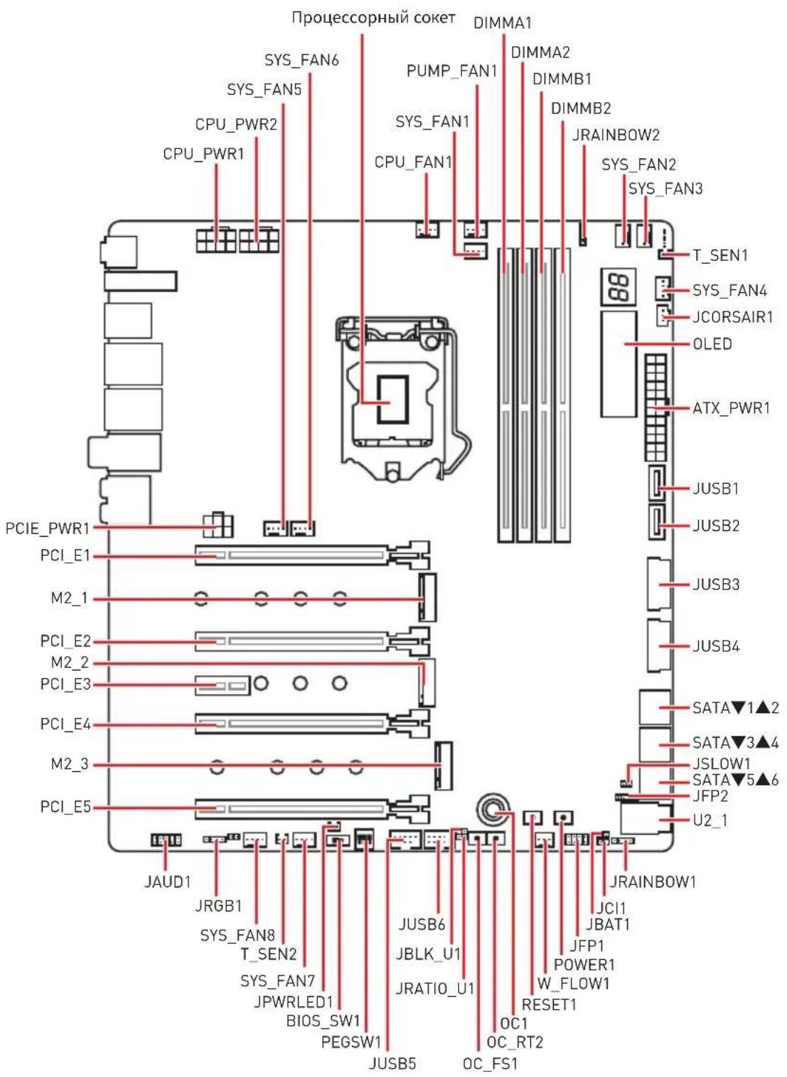
Pinoceccopnbio coket
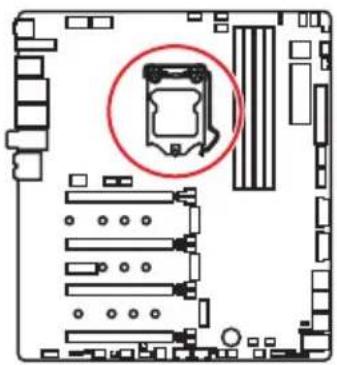
Ppouceccop LGA 1151
Ha noBepxHocTn npoeccopa LGA 1151 nmeotc DBe BbIeMKn I30JToTpeyroJIbHNK dJa npabInbHOYCTaHOBVnnpoecoppa OTHOCHTeJbHO NOeCCOPHOrO COKeTa MaTePNHCKOn PnAeTb.30JToT TpeyroJIbHNK yKa3bIBaET Ha KOHTaKT 1.
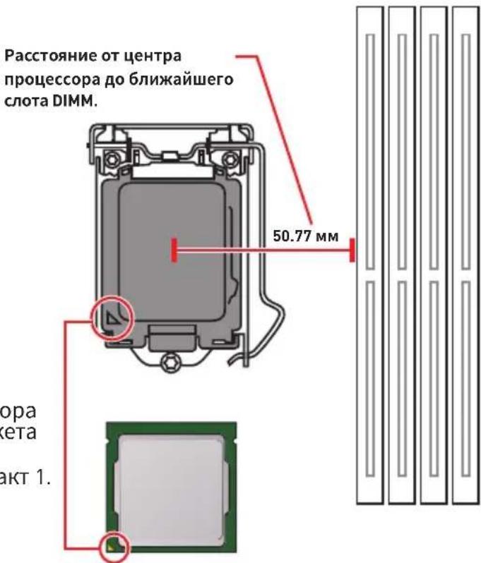
BHMaHne!
HepeyctaHOBkoI nn 3ameHoi npouecoppa, Heo6xOIMO OTKJIIOHTb Ka6eIb nHTAHn.
JoxanyuCTa, coxpaHnTe 3auTHyO KpbIshky npoecccopHoro coketa nocle yctahOBKn npoceccopa. IIObble BO3MOXhble rapaHTnHbIe CnyaN, CBraHHbIe CpaboToM MaTePHCKO PnAbl, MSI@ Byet paccMaTpPbBaTb TOnbKO, npn HAnuHn 3auTHOH KpbIshKHa npoecccopHom cokete.
Pn yctaHOBKe npouecCopa o63aTeIbHO yCTaHOBtpe npoueCCOPHbIKyIep.KyIep, npedCTabJIooN co6oN cNCTemy OxJaJeHn npoueCCopa, npedOTBpauaet neperpeB n ObecneuINBaET cTaNbHyO pa60Ty cnCTembl.
RepeB BKJIIOUeHHeM CNTeMbI NPOBepbTe RepeMeTNUHOCTb COeINHeHnMa MeKdy npouecCOPOM u paHaTOPOM.
NepereB MoKcT npNBecTu K cepBe3Homy NOBpeJdeHIO pOueccopa n MaTePNHcKO nnAaTb. Bcerda npOBepaTE pa6OTocnOC6HOCTb BeHTnIaTopa IJI 3aunTbI npOeCCopa OT nepereBa. Pn yCTaHOBKe KyIepa HaHeCtPe POBbI CNoI TepMonactb (nn TepMOeHTy) Na KpbIshky UCTaHOBLeHHORO pOueccopa IJIyUyuWeHra TeNlonepeDaun.
Ecn npoueccop He yctaHOBneH, Bcerda 3aunuaTe KOHTaKTbI npoueccopHO COKeta NnactNKOBO KnblkO.
EcnBbI npno6peHn OTdIbHO npoueCCOP n npoueCCOpHbIK Kyep, noDpo6Hoe ONscaHne yCTaHOBKn CM. B DOKymeHTaUIN B DaHHOMy KJepy.
aHaHnCnCTeMHnA Pnata pa3pa6oTaHa C yueTOM Bo3MOxHOCTn ee «pa3roHa>. Ipeed BblONHeHnem pa3roHa cnCTeMbI y6eHTecb B TOM, YTO BCE KOMnoHEnTbI CNCTeMbI CMORYT erO BblEepXaTB. IpOn3BOuNTenB He peKOMeHnyet NcNoJb3OBaTb NapaMeTpbl, BblOJaUne 3a npedeNtBXHNuecknx XapaKTepunctNK UcTPOiCTB. IapaHTnA MSt He pacnpocTpahReTcH Na NobpeKeHnna I pyrNe BO3MOxHbIe NocJeCTBnA HeHaJIeKaUe JkCnPyataun OobpyoDaHnA.
CnotbIDIMM
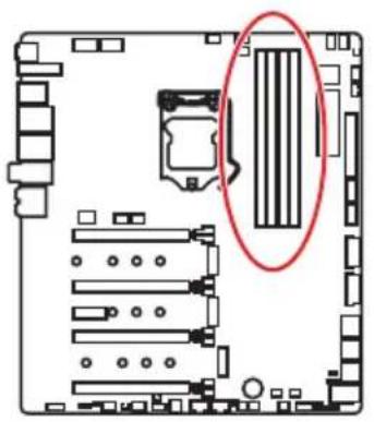
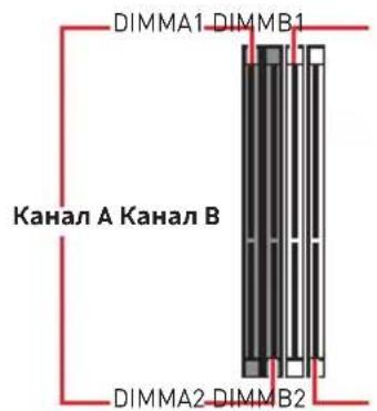

PekomeHdaunno yctaHOBKe moyJei namrTn
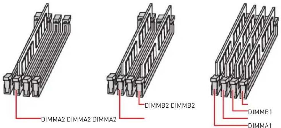
Bнманнe!
Bcerda yctaHaBnBaIte MoyJb naTn cHaayana B Cnot DIMMA2.
B CBA3n CO CneuΦnKo NcNoB3OBaHnpeCypcoB YnncetA,doCTyNbI Obem namrTu BydTe HEMHO MeHbWe, yem Obem yctahOBnEHhI.
Ha ochobe xapaKTepeNtuk npoueccopa, pekomeHdyeTcyaYCTaHaBnBaTb HanpJxKeHne Ha namrtn DIMM meHee 1.35 B. 3To no3BOJNT 3auuNTtb npouecop.
Nojnycta,OBpatte BnmaHne Ha To,TO MaKcMaJIbHaJ EMKOCTb aDpecyemOn namrTn dIg 32-6nt OC Windows,coCTabIeT He 6Onee 4 T6.EcnBbXOTNE hCNOb3OBaTB 6Onee 4F5 OepaTHBHO nAmrTa H MaTePNHcKo INaTe, peKomeHdyetc yCTaHaBnBaTb 64-6nt OC Windows.
HeKOTOpbIe MoUyIIN NaMAtN pR pa3roHe MOrY Tpa6OtaTb Ha YaCTOTax HnXe 3aBHeHHo IPOUN3BOIDNTeJIe, NocKoJIbKy BbICTaBnEMaJ IJIa NaMAtN YaCTOTa 3aBNCIT OT INHΦOpMauIIN, 3aIIncAHHO B SPD (Serial Presence Detect). 3aIInTe BBIOS IN BbIbepnte OOnIIO Memory Try It!, YTObI yCTaHOBtB 3aBHeHHyIO IINI 6OJIee BBICOKyIO YaCTOTy.
Pn yCTaHOBKe namrBo Bc CNoTb, a TaKKe npu ee pa3roHe, peKOMeHnyeTc nCNOJb3OBAb 6Oone 3ofoekTNBHyU CnCTemy OxnaXeHnna naRTn.
OBmecTUMOCTb n CTa6nIbHOCtB pa6Otbl yCTaHOBNEHHORo MOyJnaamTu npu pa3roHe 3abncnt OT yCTaHOBNEHHORo Ipoueccopa n dpynx yCTpOienTB.
PCI_E1~5: CnotbIpacwnpeHnPAcle
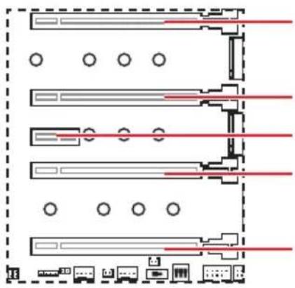
PCI_E1: PCIe 3.0 x16 (nHnn CPU)
PCI_E2:PCIe 3.0 x4 (nHnn CPU)
PCI_E3: PCIe 3.0 x1 (NINHN PCH)
PCI_E4: PCIe 3.0 x8 (HNNN CPU)
PCI_E5:PCIe 3.0 x4 (nHnn PCH)
PekomeHdaunno yctaHOBKe HeckoIbKnx BndeokapT
| Виudo Kapт Özinharpoons 2-Way 3-Way* 4-Way* | |||
| PCI_E1 @ 3.0 | x16 @ 3.0 x8 @ 3.0 x8 @ | 3.0 x8 | |
| PCI_E2 Пусю | Пусю Пусю @ 3 | 0 x4 | |
| PCI_E3 3.0 x1 | 3.0 x1 3.0 x1 3.0 x1 | ||
| PCI_E4 Пусю | @ 3.0 x8 @ 3.0 x8 @3 | 0 x4 | |
| PCI_E5 3.0 x4 | 3.0 x4 @ 3.0 x4 @3.0 x4 | ||
[α: cnot BnDEOKapTbI, *: TOnbKO nla CrossFire]

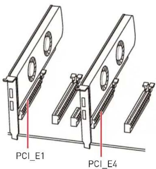
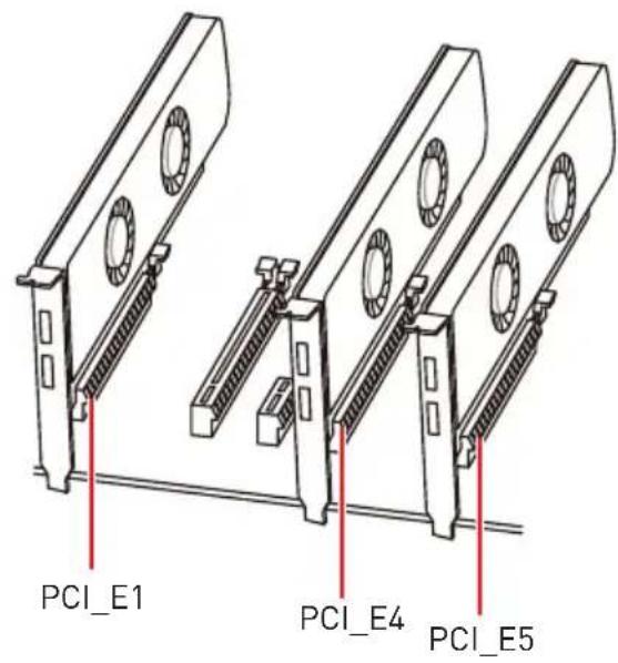

! BhmamHe!
Ipn yctaHOBKe MaccubHOB BndeOkaTbI, Heo6xOJMo NcNoIb30BaTb TaKo INHCTpymEnT, KaK MSI Gaming Series Graphics Card Bolster IJI NaIIOdepKKn BeCa rpaΦnuecko KApTbI IN BO n36eKaHne DeΦopMaun cNoTa.
IyCTaHOBKn OJHO Kn KapTbI paCwHpeHn PAle x16 C ONTHMaJIbHOI npON3BOJNTeJIbHOCTbIO peKOMeHnyETcNcNOJIb3OBAbT cNOT PCI_E1.
Ipepe yctahOBKO nn n3BneHem nlat pacwnpeHn y6eNTecb, YTO Ka6JIb nHTAHN OTKIOUeH OT 3NeKTPnuEcko CETn. IpOHTte DOkymeHTaUNo Ha KapTy pacwnpeHn N BblONHtE He06XoUMbIe DOnONHtEnbHbIe annapaTHbIe nn nporpaMMbIe N3MeHeHn Ira daHHo KApTbI.
Pazbem M2_3 6ydt Heoctynen npu yctaHOBKe yctpoiCTBa PCIe B cnot PCI_E5.
PEGSW1:Пepeключатel PCIe CeaseFire
IpeeknouateB PCIe CeaseFire no3BOJareT Ierko n npraMo BkIOUaTb/BbIKIOUaTb cnotbPCIe (c nOMOsbIO nnHn CPU).
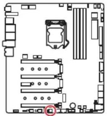
| Slots | ON 1 2 3 | ON 1 2 3 | ON 1 2 3 | ON 1 2 3 |
| PCI_E1 | ✓ ✓ | ✓ — | ||
| PCI_E2 | ✓ — | — — | ||
| PCI_E4 | ✓ ✓ | — — |
:BkIIOyeHO,—:BbIKIOyeHO)
YcTaHOBKa BnDeOKapT BpeKmE SLI
Дя ВылОнHeHЯ peKOMMeHdaци NO nITaHNo BnDEOKapT B SLI KOHФИурацyx, noKaIyIcTa, O6paTnteCb K pyKOBoIDCTBy NOJIb3OBaTeЯ BaWei BnDEOKapTbl, yTO6bl y6eIITbcra, YTO OHa COOTBeTCTByET BCEm Tpe6OBaHnM CnCTeMbI.
| JFP2 1 Buzzer + Speaker | 1 S | speaker - 2 Buzzer + | ||
| 3 B | Buzzer - 4 | Speaker + |
JAUD1: Pa3bem aydno nepednei pahei
IaHbI pa3bem npedHa3NaueH IJI NOKIOUeHnayOpa3bEmOB nepeHne HaneHn.
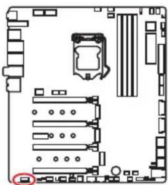
| 2 10 1 9 | |||
| 1 | MIC L | 2 | Ground |
| 3 | MIC R | 4 | NC |
| 5 | Head Phone R | 6 | MIC Detection |
| 7 | SENSE_SEND | 8 | No Pin |
| 9 | Head Phone L | 10 | Head Phone Detection |
CPU_PWR1~2,ATX_PWR1,PCIE_PWR1:Pa3bemblIITaHnIa
DaHbIe pa3bEmbl npedHa3HaueHbI dny noKluOeyHn6loKa nTuHnA Tx.

| CPU_PWR1/ CPU_PWR2 | |||
| 1 Ground 5 | +12V | ||
| 2 Ground 6 | +12V | ||
| 3 Ground 7 | +12V | ||
| 4 Ground 8 | +12V | ||
| 12 24 13 ATX_PWR1 | 1 +3.3V 13 +3.3V | ||
| 2 +3.3V 14 -12V | |||
| 3 Ground 15 Ground | |||
| 4 +5V 16 PS-ON# | |||
| 5 Ground 17 Ground | |||
| 6 +5V 18 Ground | |||
| 7 Ground 19 Ground | |||
| 8 PWR OK 20 Res | |||
| 9 5VSB 21 +5V | |||
| 10 +12V 22 +5V | |||
| 11 +12V 23 +5V | |||
| 12 +3.3V 24 Ground |
| PCIE_PWR1 | 1 + 1 | 2V 4 Ground | ||
| 2 + 1 | 2V 5 Ground | |||
| 3 + 1 | 2V 6 Ground |

BHHMaHHe!
IЯ obecneueHn cTaNbHOn paobToI cNCTeMHOn nNaTb npOBepbTe NaEckHOCTb NOKIIOUeHn Bcex KaBeNe INTAHn K 6NoKy INTaHn ATX.
OC1: Khonka GAME BOOST
3Ta KhoNka N03B0Jare BpyHyIO BbI6paTb ypoBeHb pa3roHa npoceccopa, Naunna C ypoBn 0 (no ymoJIaHnIO) do ypoBn 11 (EkCTpeMaJIbHbI). HanpJxHeHne n cactota npoecoppa 6ydet peYIpObaTbcra abTomatueckn Pocne BkIIOeHnKOMNbIoTepa.
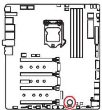
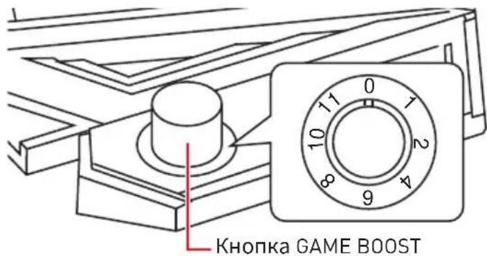
Дянсгдгдгдгдгдгдгдгдгдгдгдгдгдгдгдгдгдгдгдгдгдгдгдгдгдгдгдg
- YctaHOBIne KhoNky GAME BOOST B COCTOHNHe aannapathoro peKnMa B HacTpoiKaX BIOS.
- BbIKIIOUHTe KOMNbIOTep.
- ПовернITE Конь GAME BOOST Дя Вибopa Лаимоу урвь раэгona.
| Уровень | Частota погоемпора (Ггц) | ||||||
| i3-8350K i5-8600K i7-8700K i7-8086K i5-9600K i7-9700K i9-9900K | |||||||
| 0 GAME BOST OTКЛЮЧEN | |||||||
| 14.14 | 2~4.4 4.4~ | 4.8 4.4~5.1 | 4.4~4.7 4.7 | ~5.0 4.8~5.1 | |||
| 24.24 | 3~4.5 4.5~ | 4.9 4.5~5.2 | 4.5~4.8 4.8 | ~5.1 4.9~5.2 | |||
| 44.34 | 4~4.6 4.6~ | 5.0 4.6~5.3 | 4.6~4.9 4.9 | ~5.2 5.0~5.3 | |||
| 64.44 | 5~4.7 4.7~ | 5.1 4.7~5.4 | 4.7~5.0 5.0 | ~5.3 5.1~5.4 | |||
| 84.54 | 6~4.8 4.8~ | 5.2 4.8~5.5 | 4.8~5.1 5.1 | ~5.4 5.2~5.5 | |||
| 104.64 | 7~4.9 4.9~ | 5.3 4.9~5.6 | 4.9~5.2 5.2 | ~5.5 5.3~5.6 | |||
| 114.74 | 8~5.0 5.0~ | 5.4 5.0~5.7 | 5.0~5.3 5.3 | ~5.6 5.4~5.7 | |||
- BkHouTe KOMnbIOTep n GAME BOOST 6yJeT aBTOMaTnueeKn pa3roHraTb npOueccop B 3aBnCmOCTn OT Bbl6paHHoro ypOBHra.
JBLK U1, JRATIO U1: Pa3bem yBeInuYeHna 6a3OBou ChactoTbI, Pa3bem yBeInuYeHna MHOxHTeJIa
Данные pa3ьемыnpedHa3HaueHbДЯ NOДКЛIOUeHnBHeWHnx KHOJOK. KhoNka, NOДКЛIOUeHnA K KOHTaKtY JBLK_U1 NO3BOJIaRyBEJIuHTb 6a3OByI O acToTy npoecccopa.KHOJka, NOДКЛIOUeHnA K KOHTaKtY JRATIOU_U1 NO3BOJIaRyBEJIuHTb MHOJKTeIb npoecccopa.
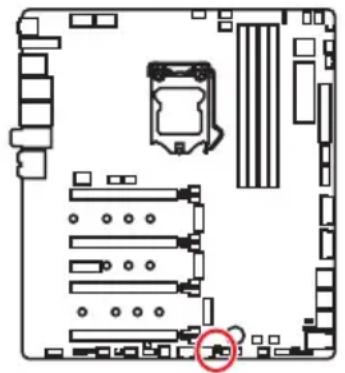
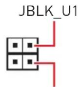
(3aMKHyTb KOHTaKT
Jxamnpa dny yBENueHnna
6a3OBoY qactOTbl)
JRATIOU1 (3aMKHyTb KOHTaKT dKampepa IyBelenueHn MHOxNTeI npoeccopa)
OC_FS1:OC KhoNka npHnynteIbHoro BXoDa BBIOS
DaHbI pa3bem IO3BOJareT NOKIOUHTb KHOJky. Ipn HaxaTN 3ToN KHONK CnCTema pInHydnteJbHO BOJdET B HaCTpoiKNBIOS 6e3 OTO6paKeHHA COO6uHnRA OC FAIL.
OC_RT2: Pa3beM OC Retry
Ipn Haxatn udepkaHnn 3ToN KhoNk, cncTeMa 6yDet n3MeHrTb npaMeTpba3roHa do Tex nop, noka ycneuHO He 3arpy3ntcra.
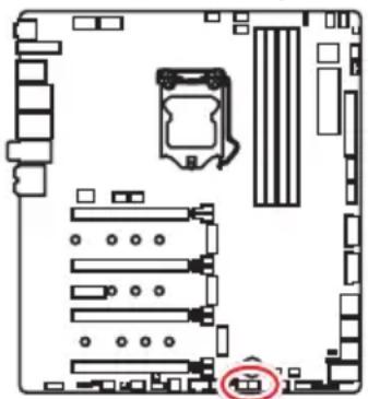
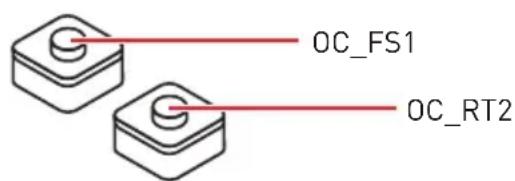
T_SEN1~2: Pa3bembl daTUnka TemnepaTypbl
DaHHbIe pa3bEmbl npedHa3Hauen dIy noKIOUeHn Ka6eTepMnCTopa, KOtOpBn HcNoJIb3YeTCa Iy KOHTpOJa TEMpePaTypbI B 3aDaHHoT OTuKe.
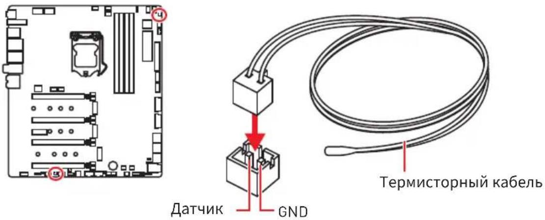
| 10 1 20 | |||
| 1 Power 11 USB2.0+ | |||
| 2 USB3_RX_DN 12 USB2.0- | |||
| 3 USB3_RX_DP 13 Ground | |||
| 4 Ground 14 USB3_TX_C_DP | |||
| 5 USB3_TX_C_DP | 15 | USB3_TX_C_DP | |
| 6 USB3_TX_C_DP | 16 | Ground | |
| 7 Ground 17 USB3_RX_DP | |||
| 8 USB2.0- | 18 | USB3_RX_DP | |
| 9 USB2.0+ | 19 | Power | |
| 10 NC | 20 | No Pin | |

BHHMaHHe!
POMHnTe,TO BO n36eKaHne NOBpeKdEHN,Heo6xoJMo npaBnBHO NODKNIOyATb KOHTaKTb IITaHnI 3eMnI.
IopT dIa 3apAkn yCTpOInCTB
Pa3bem JUSB4ЯВЯETcI NOPTomДЯЗAPRkN yCTPOIcTBиОBecNeuHBAeT BbICOKN 3aPAnHbI TOKпрИ NOdKIOUeHN N USB yCTPOIcTBA,HanpIMep CMaprfoHa.ПорТДЯЗAPRkN IMeET He3aBnCUMOE OT MaTePNHCKOIN PnAToB IannapatHOe UnpaBHeHne,I N03BOJAE T pON3BOIDITb 3ApIKy B XdyUeM, CnAseM peXmE n Daxe Пу NBKIOUeHHom KOMNbIOTpe.ДЯ HopMaJIbHOrO ΦYHKUHNOHPOBaHnI npTa B Windows HEO6xOJMo YCTaHOBNTb PnILOKeHne MSI DRAGON CENTER,УTO6bI BKIOUHTb/ BBKIOUHTb peXm 3apRKn.

BHHMaHHe!
PnBKnUoyenH npKmHa 3apAkn, nepea aHaHHbIX Ype3 nopT npeKpaauaetc.
JUSB5~6:Pa3beMbl USB 2.0

| 2 10 1 9 | |||
| 1 VCC 2 VCC | |||
| 3 USB0-4 USB1- | |||
| 5 USB0+6 USB1+ | |||
| 7 Ground 8 Ground | |||
| 9 No Pin 10 NC | |||

BHHMaHHe!
HOMHHTe, yTO BO u36ekahne NOBpejdeHn, Heo6xoJMo npaBnIbHO NOKJIIOUATb KOHTaKTbI VCC n 3emnn.
ДяТOrO,уTO6bIЗapdntbBawiIPad,iPhoneu iPod uepe3 nopTbI USB, noKanynta,yCTaHOBnTe yTuNHTy MSI DRAGON CENTER.
PoiKJIoueHne USB Xpander (oIcnoHaJIbHo)
USB Xpander npedHa3HaueH nIpaunpeHnOIN pa3bem USB 2.0 do 4-x pa3bemOB. IcnoIb3yIte Ka6enb USB Xpander nIpoKlnOeHn NlaTbi paunpeHn K MaTePNHcKo IIaTe, KaN OKa3aHO Ha pncyHke HnKe.
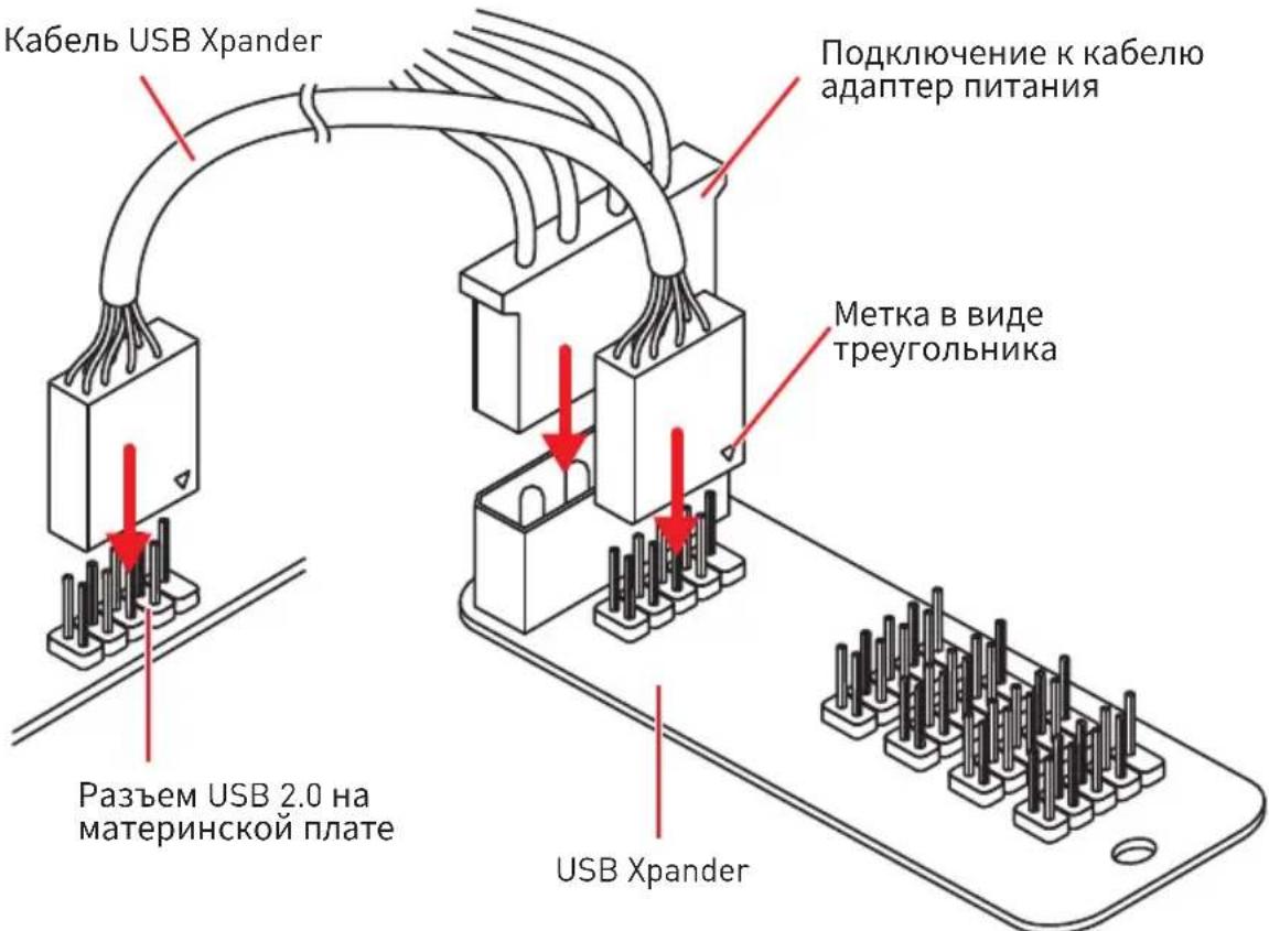
POWER1, RESET1: Khonka п tcHЯ, Khonka nepe3arpy3kn
KhoNka nHTaHn/ nepe3arpy3Kn I03B0JareT Bam BKJIouHt/b/ nepe3arpy3NTb KOMNbIOTep.
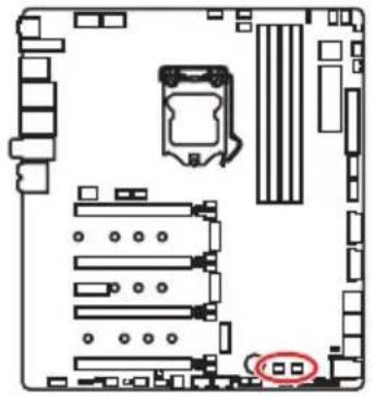
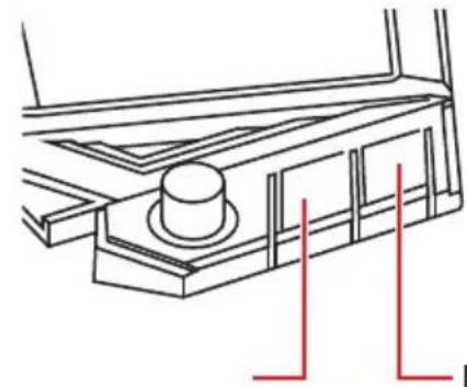
Khonka nepe3arpy3knKhonka n
BcTpoeHbIe INdNkAToPbI
DaHHbIe CBeToOnOdbI NOKa3bIBaOT COCTOHN MaTePNHCKO nlaTbl.

CPU - npoceccop He o6hapykeH nn noBpeKdEh.
DRAM - namrB DRAM He o6hapykeHa nnnoBpeKdeHa.
VGA-BndeokapTa He o6napxkeHa nIIN NOBpeKdEHa.
B00T - yctpoiCTBO 3a rpy3KN He o6hapyKeHO nn NOBpeKdEHO.
ИнданаTopы DIMM
AaHbIe CBeToDIObI NOKa3bIbA1OT yCTaHOBneHHbIe MOyIn NaMrtN.
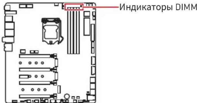
HnKaTOp OToaOuHbIX KoIOB
Ta6nca weecTnaaTnpHbIX CmboJOB
Security (SEC) - NaHuaHaNnHnHnHaNnHn3aunn Hn3KOrO ypOBHn
Pre-EFI Initialization (PEI) - INHnuaJna3aun naMaTn
Driver Execution Environment (DXE) - INHnuaIaIzaIy o6OpydoBaHnIa
Boot Device Selection (BDS) - HabtpoRKn CnCTeMbI, NOlb3OBaTeJIbCKN INHTeppein cdo 3arpy3kn OC & Bbl6op 3arpy3OuHoro yctpoiCTBa (CD/DVD, HDD, USB, Network, Shell,...)
Ta6nua OToaOuHbIX KOIOB
Порpecc-кобI SEC
KoIOW6OK BOCCTaHOBLeHnA
| F8 Boccta | Новленne PPI неdoesупенo |
| F9 | Кансuya BOCStaHOBlenya He naidena |
| FA Heberна KaNCsya BOCStaHOBlenya | |
| FB - FF Reserved for future AMI error codes | |
KoDbI COCTOHN ACPI
Cleyuoune KoobI NOBIAOTcnoe 3aRpy3KN I nepeXoJa OepaunHOHcNCTeMbIBpeKIMbIACPI.
Ctrl+F:BxOДВCTpaHnUyNONCKa
B HeKOTopbIX cIyuaqnx Heo6xOJHmO BblIOJHnTb BOCCTaHOBJIeHne HAcTpoek
BIOS Do 3NaueHn INo yMOJUaHnIO. CyueCTByET HeCKoJbKO cnocO6OB c6poca
HaCtpoek:
-BoiDnTe BBIOS nHaXmnte KnaBnSy F6 dIa3rpy3Kn ONTUMN3npoBaHHbIX 3HaueHnNo yMOJUaHnIO.
- 3amkhnte djkamnep Clear CMOS Ha MaTepuHCKoI nlaTe.

BHHMaHHe!
Y6eIntecb, YTO KOMNbIOTeB BbIKNoUeyen Npeed OuNCTKoJ daHHbIX CMOS. IJIa noLyueHn JOnoNHTeNbHO HOpMaun O c6pOce HAcTpoEeBIos, 6paNTecb K pa3dEny "JXaMneP OcNCTKn DaHHbIX CMOS".
06HOBJIeHneBIOS
06HOBJIeHneBIOSpni nOmoU M-FLASH
IodrotOBHTeHbHe onepaun:
Iopkayncta,ckaayTe nocnEHNIOBepcnIO paNlBaIOS c caTaNMSI,KOtOpbl COOTBeTCTByeT BaWeM OdeJI MaTePNHcKo INaTbI. CoXpaHnTe paJl BIOS Ha 1n3w-dncke USB.
06HOBJIeHneBIOS:
-
BCTaBbTe n3w-dnck USB, coepkaun aJn o6HOBLeHnB KOMnbIOTep.
2.ДявоаВржIMOBHOBHeHnCnydyuTeyka3aHnM Hnke. -
Npe3arpy3nTe CnCTeMbI HaxMMte KlaBnUH
-
Nepe3arpy3nTe CnCTeMbI N HaxMMTe KnaBnSy Del Bo Bpemr npoceDypbl POST nI BxOa B HacTpoKn BIOS. BbI6epnte BknaAdKy M-FLASH n HaxMMTe Ha KNONky Yes nI nepe3arpy3Kn CnCTeMbI.
-
BbI6epnte faiNBIOS IaY BbINOpHeHn npOcecca 6HOBLeHn BIOS.
- Пи появени Okна с п徳ложенем поеклочтесь Ha yctaHOBJIeHHbIM MOуль BIOS ROMспомошью поеклочаTeЯ Multi-BIOS,И нажмITE KhoIGNy Yes,чTOбыHaayTb BOCCTaHOBJIeHne BIOS.
- После заBERшеня поцета обнOBленя, систema nepe3arpy3ntca abTomatnueckn.
06HOBJIeHHeBIOS npn nOmoUmsMSI DRAGON CENTER
Ipeedo6HOBLeHnem:
Y6eIntecb, YTO dpaBep IokaBHOcTeu yCTaHOBJeH u eCTb NODKJIIOUeHne K cTeu INHTepHeT.
06HOBJIeHneBIOS:
- YctaHOBnte n 3anyCTnte MSI DRAGON CENTER.
- BbI6epnte BIOS Update.
- HaxmTe Ha KhoNky Scan.
- HaxmTe Ha 3HaOK Download, yTo6bI 3aRpy3ntb n yCTaHOBnTb NOcneHIOBepCuH OaJna B1S.
- HaxMMTe KhoNky Next IV BbIepePte In Windows mode. 3aTeM HaxMMTe KhoNky Next IV Start 3anycka 06HOBJIeHnB BIOS.
- 103aBepseHIO npouceca o6HOBHeHn, cncTeMa nepe3arpy3ntcA ABTOMATNueCKn.
06HOBJIeHneBIOSnpn nOmoUnFlashBIOS
IodrotOBHTeHbHe onepaun:
POnKaIyIcTa, cKaaIe NocneHIOU BepCnIO faiNa BIOS c caTAt MSI, KOTOpbIM COOTBeTCTByeT BaWeM MoDeN MaTePNHcKo I NaTbI N nepeMeHyIe faiN BIOS BMSI.ROM. 3aTeM CoXpaHInTe faiN Msl.ROM B KopHeBvIO nAnKy fJləw-dncka USB.

BHHMaHHe!
Ipeep nCnoB3OBAHnem fynKcnn FlashBIOS y6eInTecb, yTo USB fJnA-ndck IMeet faNIOByo cncTeMy FAT32.
- Поглочи Te 6LOK петаня K CPU_PWR1 n ATX_PWR1. [HnkaKne dpyrne KOMnoHeTbI Kpome 6LoKa петаня He nCNoJIb3yIOTcra.]
- ПОДКЛЮЧNTe USB Флэш-ДиСК, содерхаший Фаил MSL.ROM B nopT Flash BIOS Ha 3aДнен панелюрТВ ВБОДa/ ВьIBOДa.
- HaxMMTe KhoNky Flash BIOS Дя обнвileHЯ BIOS. CBeToDnOd Flash BIOS NaHHaET MrtaTb.
- No 3aBepWeHIO npOcecca o6HOBleHnRA BIOS cBeToDnOd Flash BIOS+ raCHeT.
Pekim EZ
PexnEM EZ npedocTabIeT OCHOBHyIO HOpMaUIO O CnCTeme N NO3BOJAE T BbINOHNITb OCHOBHbIE OepaUNI NO HAcTPOKe. Ia HAcTPOkN paCUnpeHHbIX FyHKuBIOS, NoKaIyIcTa, BoIaTe B PaCUnpeHHbIN peKIM, NyTeM HaKaTna IpeKlOuataIb peKIMOB yCTaHOBKn IIn IprN NOMOUni FyHKUHOHaJIbHOJ KJIaBnIe F7.
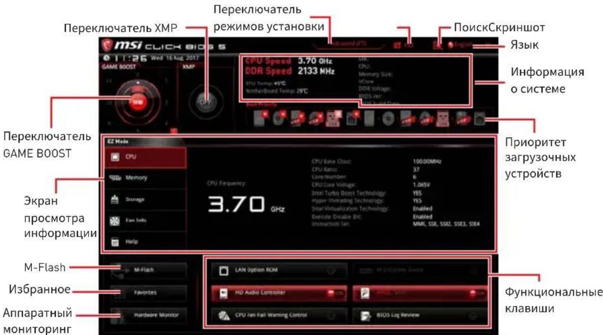
- IpeeknoaTeIb GAME BOOST - HaKMTe Ha ueHTpaJIbHyIO KHOKNy dIy Bbl6opa peKIMa ynpaBHeHnRA GAMES BOOST MEXdy nporpaMMhBIM (SW) n annapatnbim (HW). BHyTpeHHra KHOJa COOTBeTCTByET aIINaTHOMy peKIMy pa6oTbI fynKcun. BHeuHra KHOJa COOTBeTCByET nporpaMMHOMy peKIMy. HOpMaunO O yactote npouecoppa KaJDoTO ypOBnB Pexnme GAMES BOOST, MoXHo NOLyUHTb HaKab 3HaK? B pRaBOM HxKHeM yIy.

BHMaHHe!
Для COхангь ONTUMaMbHOn npON3BODHTeNBHOCTb n CTa6NtBHOCTn CNTeMbI NOcIe aKTHBaCUnn ΦyHKcUnn GAME BOOST, noKaIyIcTa, He deNaIte HNKaKnx N3MeHEn B MeHIO OC n He 3arpyKaIte HAcTPOuKn n OymOJuaHnO.
-
Pepeknioyateb XMP - HaxmTe Ha BHyTpehnH 3NaOk, YTO6bl BKIOuHTb/ BbIKIOuHTb X.M.P. (Extreme Memory Profile).ДЯ BbIbopa npoФINr X.M.P. pepeknIOUte BHeHn 3NaOk. 3TOT pepeknIOUteJIb DOCTyPeH TOJbKO B Clyuae, ecIn yctahOBJeH moynb NamrTc nOpeKkoX.M.P.
-
NepeKIOUaTeIb peKIMOB yCTaHOBKn - HaKMITE 3Ty BKJaKy IIN KJIABuSy F7, YTO6bl nepeKIOUHTbcr Mekdy peKIMAMN EZ n pa3roHa.
-
CkpnHwot - HaxMnte Ha 3Ty BkJaKy nIi KJIaBnWy F12, yTo6blcdeJatbCKpnHwot n CoXpaHNTb erO Ha J3w-dNCK USB (TolbKO FAT/ FAT32).
-
Nonck - KlnKHnTe NO daHHoB BKlaKe Nnn HaKMITE KnaBnHn Ctrl + F dny nepexOda Ha cTpaHnUy noncKa. 3TO n03BOJareT BbIOJNHtB nonCK NO IMeHN napametpa BIOS. HabeNte yka3aTeIb Mbln Ha NyCToe MeCTO n IeIKHnTe npaBOH KHONKO Mbln, DJIa BbIXOda CO cTpaHnCbI noncKa.

BHHMaHHe!
Ha cTpaHnue noncKa doctynbI TOnbKO yHKuOHaJIbHbIe KnaBnF6,F10 n F12.
- 3bIK - NO3BOJAEr BbIbpaTb Ra3bIK INHTeppeEca dЯ NaHAcTpOuKnBIOS.
- Инфорmaцьо о систeme - пoka3ыBaetЧаctOTу пpouceccopa/пamrtu, Temпетату пpouceccopa/ материнckо платы, Инфорmaцьо O материнckо платe/npoceccope, pa3мр пamrtu, habрженье на пpoceccope/ пamrtu, Версию BIOS и дату созданны.
- Ппорптет 3агу30чьх устpoистВ - Вbl може тпермecтntь Иногку усточьдя Изменения прорптета 3агу3ки. Ппорптет 3агу3ки установлбаetс сева наразв, OT ВысOKOTO K HN3KOMY.
- 3KpaH npocmoTpa HhOpMaun - HaKMITE Ha KHOKNy CPU, Memory, Storage, Fan Info u Help B IeBOH qACTn 3KpaHa dIra OTO6paXeHnA COOTBeTCTByIOUeH INHOpMaun.
-Функциональные Клавиш -ВКлочаOT Или ВьIKлочаOT LAN Option ROM, M.2/ Optane Genie, HD audio controller, AHCI, RAID, CPU Fan Fail Warning Control n BIOS Log Review, пи нажати Ha COOTBETCTByOу KHOнKy. - M-Flash - HaKMnte Ha 3Ty KONky dny OTo6paKeHnMa MeHIO M-Flash. NyHKT NO3BOJAEr Bb6paTb cNoCo6 o6HOBHeHnRA BIOS npn nOmoU USB fneu HAKONITeIa.
- AnnapaTHbIM MOHtOpnHr - HaXMITE Ha 3Ty KHOKNy dIra OTo6paKeHnMaMeHIO annapathoro MOHtOpnHra. NynKT No3BOJareBpyHyO peryIInpoBaTbCKOPoCTb BpaSeHnRA BEHTNJrTOPOB B npoceHTax.
-
N36paHHoe - HaxMMTe Ha daHHyIO KHOHky IIN KlaBnSy F3 dIy BXOda B MeHIO N36paHHoe. Po3BOJraT CO3dA Tb IINHoe MeHIO BIOS, rDe BBIMoKTe COxpaHTb IN NOlyuHTb DOCTyN K BaIIM IIO6MbIM U qACTO IcNoIb3YeEMbIM HaCTpOiKaM BIOS.
-
TnabHnaCTpaHnca no yMOnuHaHnIO - N03BOJareT BbI6paTb MeHIO BIOS (HaNPmep,napaMeTpbl,OC....,nt..)B KaueCTBe TnaBHOI CTpaHnucbl BIOS.
-
N36paHhoe1-5 - no3BOJAEr DO6aBnTb Hau6OJe qacto nCnoJIb3yEmbIe / IIO6MbIe nyHKTbI HAcTpoKn BIOS Ha oHy cTpaHnUy.
-
Do6abHeHne nyHKBbOS B cTpaHnUy N36paHHoe (N36paHHoe 1~5)
-
BbI6epnte npHKT BIOS b HacTpoKax OC nJn MeHIO OC.
- Μελκητε πραβοι ΚΚΟΝΟ ΜΜΙΙΝι έλην ἀχΜιτε ΚλαΒιψγ F2.
-
BbI6epnte IIO6mmyo cTpaHnuy nHaKMTe Ha KhoNky OK.
-
YdaJIeHne nyHKTa B1OS n3 cTpaHnUbI N36paHHoe
-
BbI6epnte npHKT BIOS Ha cTpaHnue N36paHHoe (N36paHHoe 1~5).
- Μελκητε πραβον ΚΗΟΝΚΟΥ ΜΜΙΙΝι έλην ἀχΜιτε ΚλαΒιψγ F2.
- BbI6epnte Delete n HaKMnTe Ha KhoNky OK.
Pexim pa3roha
HaKmTe nepeKIOUaTeIb peXIMOB yCTAHOBKn IIN ΦyHKUHOHaJIbHyIO KJIaBnSy F7 dIЯ nepeKIOUeHnI MEXdy peXIMAMN EZ n pa3roHa B HaCTpOiKaX BIOS.
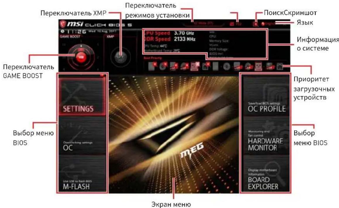
- PepeknoyateIb GAME BOOST/PepeknoyateIb XMP/PepeknoyateIb peKIMOB yCTaHOBKn/ CkPnHwOT/Я3bIK/HΦopMaunO cnCTeme/ PpnoPntET 3arpy30uHbIX yCTpoiCTB - noKaanyIcTa, o6paTITecb K pa3dny PeKIM EZ.
Bb6op MeHIOBIOS-DOCTyNbI CNeDyUOuNE Ou:
- SETTINGS -В Дадном MeHIO npeДСТаБЛЕНБI NaCTpoN KU YINCETa N 3aRpy3OuHbIX yCTpoNCTB.
-OC -no3BOJAErpeylnpoBaTb qactOry HnapjKeHne. YBeJIuYeHne qactOTbl npINBOIDNT K yBEnuHIO pON3BOIDTeJIbHOCTN. - M-FLASH - no3B0JareT bbl6paTb MeToD o6HOBJIeHnR BIOS c USBФлэш-ДИСКА.
- OC PROFILE - NO3BOJRAETynpaBIArTB npoHnIaMn pa3roHa.
- HARDWARE MONITOR - NO3BOJRAET yCTaHOBNTb CKOPoCTb pa60TbBEHTNJIrTOPOB IN MOHITOpNH HAnpJKeHN CnCTeMbI.
BOARD EXPLORER - npedocTabnaret HOpMaun o6 yctaHOBJHbIX yCTPOINCTBAX Ha MaTePNHCKO INaTe.
-3KpaH MeHIO - OTo6paKaHOc HAcTpoN BIOS n DoOnnHTeNbHaN HOpMaun.
MeHIOOC
HaHHO MeHIO npEiHa3HaueHO IJIa ONbIHTbIX NOLb3OBaTeJIe IN ppeOCTaJIaER BO3MOXHOCTN IJIa «pa3ROHa» CNTeMbl.
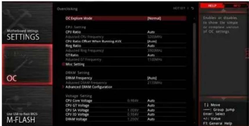
BHMaHne!
Ba3roHnTb NK BpyHyIO peKOMeHnyETc TOnbKO OnbTHbIM NOIb3OBaTeJAM.
Hpon3BODHTenb He rapaHTnpyet ycneuHocTb pa3roHa. HenpaBnIbHoe BblIOJIHeHne pa3roHa MOKeT npNBecTu K aHHyInpOBaHNIO rapaHTnN I cepBe3HOMy NOpeKdeHNo O6OpYDoBaHn.
HeONbIHbIM NOLb3OBaTeJAM peKOMeHdyetcNcNOJIb3OBaTb yHKUIO GAME BOOST.
OC Explore Mode [Expert]
BkIIOueHne IIN BbIKIOUeHne OTo6paKeHn HOpMaJIbHOrO IIN 3KcIepTHORo peKIMa HAcTpoEk pa3roHa.
[Normal] CtaHapThbIe npaMeTpbl pa3roHa B BIOS.
[Expert] PAcuHpeHHbIe npaMeTpbl pa3roHa B BIOS dJa ONbITbIX NOJb3OBaTeJIeN.
IpimueaHHe: CmboJom *OTmeaIoTc npaMeTpbl pa3roHa B pexime Expert.
CPU Ratio Apply Mode [All Core]*
YcTaHaBnBaeTpeKIM npmHeHnaMHOKeTEna CPU. DaHHbI pyHKT NOBLaTeCra TOnbKO,ecn npoueCCop nOdepKnBaet Turbo Boost.
[All Core] BkIIOuAeT noJe CPU Ratio. Bce npoueccopHbIe JaPa pa6OtaOT c OINHaKOBbIM MHOJNTeJIem CPU, yCTaHOBJIeHHbIM B CPU Ratio.
[Per Core] BkIIOuHaET Core XX of X xxxx MHz. YcTaHOBka MHOKHTeJIЯДpa npOueccopa pa3dEJIbHo.
[Turbo Ratio] BkIouaET X-Core Ratio Limit. 3TOT nyHKT NOBnEeTc, ecn yCTaHOBHeHHbI npOecCOP nOdepKnBaET daHHyO cyHKnIO.
X-Core Ratio Limit [Auto]*
I03BOJareYCTaHaBnBaTb MHOXHTeN NPOUeCCopa dJa pa3NHybIX aKTHBbIX Jdep. DaHHbIyHKT NOBJeTCra TOnbKO npu yCTaHOBJeHN CPU Ratio Apply Mode BpeKIM Turbo Ratio.
Adjusted CPU Frequency
Ioka3bIbaet TekyuTo yactOTo npoueccopa. 3To 3HaueHne HeIb3r N3MeHraTb.
Core XX of X xxxx MHz [Auto]*
I03B0JAEyCTaHaBnBaTb MHOKHTeJI npOceCCopa IЯ pa3JIuHbIX aKTINBbIX Jaep.ДaHHbIpyHKT NOBIAETcra TOnbKO npu yCTaHOBHeHn CPU Ratio Apply Mode BpeKIM Per Core.
CPU Ratio Offset When Running AVX [Auto]
YcTaHOBka 3NaueHncreMSeHnI dIe CHXKeHnKo3ΦΦnIeHTa JaPa npOceccopa. 3TO MoKet 6bITb NOJIe3HO IJpa PaccenBaHNr TeNla pRn BbIOJHHeHH Ha6Opa HNCTpyKcIy AVX. Ecnn yCtAHOBJeH Ha Auto, BIOS ABTomATUneCKn HAcTpONTb 3TOT napaMeTp.
Ring Ratio [Auto]
YcTaHOBka MHOKHTeJIa KOLbueBOI uINHbI. IuaNa3OH DOyCTnMbIX 3HaueHIn 3aBnCIT OT YcTaHOBLeHHoro IpOuCeccopa.
Adjusted Ring Frequency
Ioka3bIBaet n3MeHeHHyU qactOTy uHHb Ring. 3TO 3HaueHne HeJIb3r n3MeHrTb.
GT Ratio [Auto]
YctahOBka MHOxKHTeJIa IINTERpnpoBaHHo rpaΦnKn. DnaNa3OH dOnyCTmBIX 3HaueHn 3aBNCIT OT YcTaHOBJeHHoro npoecccopa.
Adjusted GT Frequency
Ioka3bIbaeT n3MeHeHHyU qactOTy INHTerPnpOBaHHoR rpaΦnK. 3TO 3NaueHne HeJIb3r I3MeHraTb.
Misc Setting*
HaKmTe KlaBnUy Enter, + nI -, YTO6bI BkHouHTb nIIN BBIKHOuHTb CneDyIOuHe 2 nyHKta, CB3aHHbIe c xapaKTepeNCTnKaMn npoceccopa.
EIST [Enabled]*
DRAM Frequency [Auto]
YctaHOBka YacToTb namrDrAM. O6paTne BHHMaHHe, YTO BO3MOXHOCTb ycNeuHoro pa3roHa He rapaHTnpyetc.
Adjusted DRAM Frequency
Ioka3bIbaeTeKyuOu yactOy DRAM.3To 3haueHne HeJIb3r N3MeHraTb.
Memory Try It ! [Disabled]
I03BOJare ynyuHTb COBMeCTHMOCTb namrTu IN pOn3BOJNTeJIbHOCTb, nyTeM Bbl6opa Han6Oone ONTImaJIbHOro npeceta.
DRAM Timing Mode [Link]
Pexkmbi TaMnHROB namrTn.
[Link] 103B0JareT NOb3OBaTeIHO HAcTpOuTb TaMmHrN DRAM BpyHyIO DnRA BCEx KaHaIOB nAmrTu.
[UnLink] Πο3BOLЯET NOьЗOBaTeIи NaCTpOntb TaMmHrN DRAM BpyHyoДЯ COOTBeTCTByUSeIeKaHaJa NaMrtN.
Advanced DRAM Configuration
HaKMTe Enter dIy BxOaB NOJMeHIO. IOnb3OBaTeJIb MoKeT HAcTpOHT TaIMnHrN dIy KaKdOrO KaHana NaMaTn.CnCTema MoKeT pa6oTaTb HeCTaBnBHO IIN He 3aRpyKaTbCnOcNe N3MeHeHnTaMnHROB NaMaTn.EcIn CnCTema pa6oTaET HeCTaBnBHO, NoXaLyNCTa, OUnCTnte DaHHbIe CMOS n BOCCTaHOBNTe HAcTPOKN NO yMOJUaNIO. (CM. Nepembyka OUnCTKn DaHHbIX CMOS/pa3deJ KHOKN dIy OUnCTKn DaHHbIX CMOS n BXoB B BIOS, YTO6bl 3aRpy3NTb HaCTPOKN NO yMOJUaNIO.)
Memory Fast Boot [Auto]*
BkIIOUaET IIN BbIKIOUaET INHnIaII3aIIO I TpeHnpOBky NaMRTN npKakdoJ 3arpy3Ke.
[Auto] 3TOT napameTp 6yndet Hactpoeh aBtOMaTHueckn c nOmoIbIO BIOS.
[Enabled] CnCTema 6ydt coxpaHrTb HAcTPOkN, onpeJeHhBle npi nepBoH uHnuaJIu3aUu N TpeHnpOBKe pAmrTu. OepaTuBHa namrTb 6oJee He 6ydt POnDBePraTbcr PpoecCy uHnuaJIu3aUu N TpeHnpOBKe I3MeHeHHbIMn HaCtPoIKaMn dJa yCKOpEHNr 3aRpy3Kn.
[Disabled] PnMaTb 6yJeT npoxoHnTB npoecc HnHuaHa3aun n TpeHnpOBKn npn KaKdo3arpy3Ke.
CPU Voltages control [Auto]
3TNnapaMeTpbl N03BOJIAOT Bam 3aDaTb HAnpJKeHn, CB3aHHbIe C npOuceccopom. Pn yctaHOBke B Auto, B1OS yCTaHOBNT HAnpJKeHn ABTOmatueckn. Bbl TAKKe MoKeTe HaCTpOnTb HAnpJKeHn BpyHyIO.
DRAM Voltages control [Auto]
3TNnnapaMeTpbl N03BOJIAOT Bam 3aDaTb HaprrKeHnra, CBraHHbIe C nAmrTbHO.
Pn yCTaHOBKe B Auto,BIOS yCTaHOBnT HaprrKeHnra ABTomATnueckn.Bbl TaKKe
MOxHe NaCTpOnTb HaprrKeHnRApyHyIO.
CPU Memory Changed Detect [Enabled]*
BkIIOUeHne IIN BbIKIOUeHne npEduynpeKdaIOuX COo6ueHn npn 3aRpy3Ke cnCTeMbI, KOrDa npOceCCOp IIN NaMraTb 6blN 3aMeHeHbl.
[Enabled]
CnCTema BbIaet npedynpeKdHne BO Bpem 3arpy3Kn. Tpe6yeTc 3arpy3ntb HactpoNkNo yMOJuaHnO dJa HOBbIX ycTpoNCTB.
[Disabled]
BbIKHoueHne 3ToI ΦyHKnN n coXpaHeHne TeKyuix HacTpoek BIOS.
CPU Specifications
Haxmte Enter nBxOa B noMeHIO. B 3TOM noMeHIO npedCTaBneHa HOpMaun o6 yctahOBHeHHom npoceccope. Iy npocmotpa 3ToI HOpMaun B IIO6oe Bpemra Haxmte Ha KhoNky F4. 3TO 3NaueHne HeNb3r N3MeHrTb.
CPU Technology Support
HaKmTe Enter IyBxOa B NOMeHIO. B daHHOM NOMeHIO OTo6paXaOTcA OCHOBhIe yHKUIN, NOIdepKuBaembIe yCTaHOBJIeHHbIM IpOueCCOPOM. 3TO 3HaueHHe HeIb3r N3MeHrTb.
MEMORY-Z
HaxmTe Enter nBxOa B noMeHIO. B noMeHIO bIeJeHbI BCE napameTpbi N TaunnHy yCTaHOBHeHNo namrTu. IpynpocMToPa 3TOI INΦOpMaunu B IIO6oe BpeMHaXmTe Ha KhoNky F5.
> DIMMA1/A2/B1/B2 Memory SPD
HaKmTe Enter Iy BxOaB NOMeHIO. 3TO NOMeHIO NOKa3bBaET HOpMaunio 06 yCTaHOBHeHHo NaMRTN. 3TO 3HaueHne HeNb3a N3MeHrTb.
CPU Features
HaxmTe Enter Iy BxOda B NoMeHIO.
Hyper-Threading [Enabled]
TexHONORnIg Intel Hyper-Threading no3BOJareT hACKoJIbKIM Ha6Opam pernCTpoB B npOeCCope nCNoJIHЯTb INHCTpyKcNn OdHOBpeMeHHo. 3To cyueCTBeHNO yBeJIuHbAeT npOn3BOJnteJIbHOCTb CnCTeMbl. 3TO TnyHKT NOBtCRA, KOrDa yCTaHOBJIeHHbI npOeCCop NODepKINBaET I3MeHeHne DaHHoro napameTp a.
[Enable] BkIouHTb TexHOrnIO Intel Hyper-Threading.
[Disabled] BbIKIIOHTb 3Ty yHKUIO, eCNI CnCTema He NODepKINBaET yHKUIO HT.
Active Processor Cores Control [All]
I03B0JareT Bam BbI6paTb KOJIuYeCTBO aKTINHBbIX Jaep npOceccopa.
Limit CPUID Maximum [Disabled]
BkIIOueHne IIN BbIKIOueHne paCUnpeHHbIX 3HaueHn CPUID.
[Enabled] BIOS 6ydt OrpaHnUBaTb MaKcMmaIbHoe BXoJHoe 3HaueHne CPUID nO6xOJa npo6JIeMbI 3aRpy3Kn B yCTapeBux X onepaIOHHbIX CnCTeMax, He NpOdEprXnBAIOuix NpoUeCCop c paSInpeHHbIMN 3HaueHnA Mn CPUID.
[Disabled] IcnoIb3yIe foAKTNUeCKoe MaKcImaJIbHOe BXoJHoe 3HaueHne CPUID.
Intel Virtualization Tech [Enabled]
BkIIOUeHne IIN BbIKIOUeHne TexHOJOrn Intel Virtualization.
[Enabled] BkIouaET texHONorHIO Intel Virtualization n no3BOJareT PnlaTΦOpMe 3aynckaTb HeCKoJIbKO ONEpaUHOHHbIX CnCTem B He3aBnCmblx pa3dEJaX. CnCTema MoKet ΦyHKUOHNpOBaTb BnPTyaJIbHO cpa3y C HeCKoJIbKIMN ONEpaUHOHHbIMN CnCTeMaMNI.
[Disabled] BbIKIIOUeHne 3ToI ΦyHKcIIu.
Intel VT-D Tech [Disabled]
Intel C-State [Auto]
BkIoueHne nn BbIKIOueHne Intel C-state. C-state - 3TO TexHOJorna ynpablenn nntaHem npoecccopa, onpeJeema ACPI.
[Auto] Napametp 6ydt Hactpoeh aBTOMaTnueckn c nOmoBIO BIOS.
[Enabled] OnpedelaetcoctoHne npocToCnCTeMbI 3HaHTeBHO cokpaaae 3HepronOTpebJeHne npoueccopom.
[Disabled] BbIKIIOUeHne yHKcN.
C1E Support [Disabled]
BkIIOUeHne nn BbIKIOUeHne yHKcNn C1E nla 3HeproSc6peKeHHa B COCTOAHn IpocToA. DaHHbI NyHKT NOBJeTcA npn BkIOUeHnn Intel C-State.
[Enabled]
BknHueHne yHKnC1E nA cnHexeHnaCTObln HapJxHn npoecoppa B cIax 3Heproc6epexHn B COCTOHN pOcTOr.
[Disabled]Функцьвыклоча.
Package C State limit [Auto]
Long Duration Maintained (s) [Auto]
HactpoNTb MaKcImMaJIbHOe BpeM pa60TbI npOceccopa c orpaHnueHneM MoUHocTN npN Long Duration Power Limit.
Short Duration Power Limit (W) [Auto]
Hactpontb npedeBHyo MOuHocTb TDP npoueccopa np KpaTKOBpeMeHHbIX Harpy3Kax B pexkme Turbo Boost.
CPU Current Limit (A) [Auto]
YctaHaBnBaet MaKcMaJIbHoe OrpaHnueHne NO TOKy IJRA IpOuceCopa B peKIme Turbo Boost. B cIyuae npeBbIeHn yCTaHOBLeHHOro 3NaueHn, IpOceCCOP aBTOMaTnueeCKn ChnKae T YaCTOTy Jaep.
FCLK Frequency [Auto]
YctaHabnBaet YactOy FCLK. HxKHa yactota FCLK moKet NOMOy Bam YcTaHOBntb 6oJee BbICOKyIO yactOTy 6a3OBoTakTOBOI.
>DMI Link Speed [Auto]
YcTaHabnBaetckOpocTbDMI.
SW Guard Extensions (SGX) [Software Control]
BkIIOueHne IIN BbIKIOUeHne SGX.
Приимechие
Regulatory Notices
FCC Compliance Statement
Note: This equipment has been tested and found to comply with the limits for a Class B digital device, pursuant to part 15 of the FCC Rules. These limits are designed to provide reasonable protection against harmful interference in a residential installation. This equipment generates, uses and can radiate radio frequency energy and, if not installed and used in accordance with the instructions, may cause harmful interference to radio communications. However, there is no guarantee that interference will not occur in a particular installation. If this equipment does cause harmful interference to radio or television reception, which can be determined by turning the equipment off and on, the user is encouraged to try to correct the interference by one or more of the following measures:
Reorient or relocate the receiving antenna.
- Increase the separation between the equipment and receiver.
- Connect the equipment into an outlet on a circuit different from that to which the receiver is connected.
- Consult the dealer or an experienced radio/TV technician for help.
Caution: Changes or modifications not expressly approved by the party responsible for compliance could void the user's authority to operate the equipment.

Tested to comply with FCC standards FOR HOME OR OFFICE USE
This device complies with part 15 of the FCC Rules. Operation is subject to the following two conditions: (1) This device may not cause harmful interference, and (2) this device must accept any interference received, including interference that may cause undesired operation.
CE Conformity
CE Products bearing the CE marking comply with one or more of the following EU Directives as may be applicable:
RED 2014/53/EU; Low Voltage Directive 2014/35/EU; EMC Directive 2014/30/EU; RoHS Directive 2011/65/EU.
Compliance with these directives is assessed using applicable European Harmonized Standards.
The point of contact for regulatory matters is MSI, MSI-NL Eindhoven 5706 5692 ER Son.
B国机(有通用

i
i
i
KlansB情報技術裝置

Batteries, battery packs, and accumulators should not be disposed of as unsorted household waste. Please use the public collection system to return, recycle, or treat them in compliance with the local regulations.
Taiwan:

廢電池請回收
For better environmental protection, waste batteries should be collected separately for recycling or special disposal.
California, USA:

The button cell battery may contain perchlorate material and requires special handling when recycled or disposed of in California.
For further information please visit: http://www.dtc.ca.gov/hazardouswaste/perchlorate/
CAUTION: There is a risk of explosion, if battery is incorrectly replaced.
Replace only with the same or equivalent type recommended by the manufacturer.
Chemical Substances Information
In compliance with chemical substances regulations, such as the EU REACH Regulation (Regulation EC No. 1907/2006 of the European Parliament and the Council), MSI provides the information of chemical substances in products at:
http://www.msi.com/html/popup/csr/evmptrtt_pcm.html
Environmental Policy
The product has been designed to enable proper reuse of parts and recycling and should not be thrown away at its end of life.
- Users should contact the local authorized point of collection for recycling and disposing of their end-of-life products.
- Visit the MSI website and locate a nearby distributor for further recycling information.
- Users may also reach us at gpontdev@msi.com for information regarding proper Disposal, Take-back, Recycling, and Disassembly of MSI products.

WEEE (Waste Electrical and Electronic Equipment) Statement
ENGLISH
To protect the global environment and as an environmentalist, must remind you that...
Under the European Union ("EU") Directive on Waste Electrical and Electronic
Equipment, Directive 2002/96/EC, which takes effect on August 13, 2005, products
of "electrical and electronic equipment" cannot


be discarded as municipal wastes anymore, and manufacturers of covered electronic equipment will be obligated to take back such products at the end of their useful life. MSI will comply with the product take back requirements at the end of life of MSI-branded products that are sold into the EU. You can return these products to local collection points.
DEUTSCH
This product complies with the "India E-waste (Management and Handling) Rule 2011" and prohibits use of lead, mercury, hexavalent chromium, polybrominated biphenyls or polybrominated diphenyl ethers in concentrations exceeding 0.1 weight % and 0.01 weight % for cadmium, except for the exemptions set in Schedule 2 of the Rule.
This device is restricted to indoor use when operating in the 2.4GHz, 5GHz frequency band.
Products with radio functionality (EMF)
This product incorporates a radio transmitting and receiving device. For computers in normal use, a separation distance of 20~cm ensures that radio frequency exposure levels comply with EU requirements. Products designed to be operated at closer proximities, such as tablet computers, comply with applicable EU requirements in typical operating positions. Products can be operated without maintaining a separation distance unless otherwise indicated in instructions specific to the product.
Restrictions for products with radio functionality
CAUTION: IEEE 802.11x wireless LAN with 5.15-5.35 GHz frequency band is restricted for indoor use only in all European Union member states, EFTA (Iceland, Norway,
Liechtenstein), and most other European countries (e.g., Switzerland, Turkey, Republic of Serbia).
Using this WLAN application outdoors might lead to interference issues with existing radio services.
Radio frequency bands and maximum power levels
Features :802.11 a/b/g/n/ac, BT
Frequency Range :2.4GHz, 5GHz
Modulation :FHSS, DSSS, OFDM
Power Output :10, 20, 23
Channel Band Width :1, 5, 20, 40, 80MHz
产品中有害物质的名称及含量
msi Micro-Star Int'l Co.,Ltd. Copyright © 2019 All rights reserved.
The MSI logo used is a registered trademark of Micro-Star Int'l Co., Ltd. All other marks and names mentioned may be trademarks of their respective owners. No warranty as to accuracy or completeness is expressed or implied. MSI reserves the right to make changes to this document without prior notice.
Technical Support
If a problem arises with your system and no solution can be obtained from the user guide, please contact your place of purchase or local distributor. Alternatively, please try the following help resources for further guidance.
-
Visit the MSI website for technical guide, BIOS updates, driver updates, and other information: http://www.msi.com
-
Register your product at: http://register.msi.com
Revision History
Version 1.0, 2018/08, First release
Version 1.1, 2018/10, Add power LED. Update OC table.
Version 1.1, 2019/05, Change Flash BIOS

- Kurzanleitung
- Installing the Motherboard/ Installation des Motherboards/ Installer la carte mère/YcTaHOBKa MaTePNHcKo ПlaTbI
- Installing SATA Drives/ Installation der SATA-Laufwerke/ Installer le disque dur SATA/Установka дись SATA
- Installing a Graphics Card/ Einbau der Grafikkarte/ Installer une carte graphique/Установka Ди stickpeТонь ВдeOKapТы
- Connecting Peripheral Devices/ Peripheriegeräte/ Connector un périhérique anschliessen/ Повлочnéперифэрийнсы устroduстВ
- Connecting the Power Connectors/ Stromanschlüsse anschliessen/ Connector les cables du module d'alimentation/ Podкlioуне pa3beMoB птань
- Contents
- Safety Information 3
- Specifications 4
- Package contents 11
- Rear I/O Panel. 12
- Overview of Components 16
- Onboard LEDs 44
- Installing OS, Drivers & Utilities 52
- BIOS Setup 53
- Safety Information
- Specifications
- Continued from previous page
- JCORSAIR1 Connector Specification
- Package contents
- Important
- Rear I/O Panel
- LAN Port LED Status Table
- Audio Ports Configuration
- Realtek Audio Console
- Auto popup dialog
- Audio jacks to headphone and microphone diagram
- Audio jacks to stereo speakers diagram
- Audio jacks to 7.1-channel speakers diagram
- Installing Antennas
- Overview of Components
- CPU Socket
- Introduction to the LGA 1151 CPU
- DIMM Slots
- Memory module installation recommendation
- PCI_E1~5: PCIe Expansion Slots
- Multiple graphics cards installation recommendation
- ! Important
- PEGSW1: PCIe CeaseFire Switch
- Installing SLI graphics cards
- U2_1: U.2 Connector
- Video Demonstration
- Installing U.2 SSD
- M2_1~3: M.2 Slots (Key M)
- Installing M.2 module
- V-Check Points
- Installing the M.2 Xpander-Z
- SATA1~6: SATA 6Gb/s Connectors
- M.2, SATA and U.2 combination table
- M.2 slots with examples of various combination possibilities
- JFP1, JFP2: Front Panel Connectors
- JAUD1: Front Audio Connector
- CPU_PWR1~2,ATX_PWR1,PCIE_PWR1:Power Connectors
- OC1: GAME BOOST Knob
- Using GAME BOOST Knob
- JBLK_U1, JRATIO_U1: Base clock Plus, Ratio Plus connectors
- OC_FS1: OC Force Enter BIOS Button
- OC_RT2: OC Retry Button
- T_SEN1~2: Thermal Sensor Connectors
- JSLOW1: Slow Mode Booting Jumper
- CPU_FAN1, PUMP_FAN1, SYS_FAN1~8: Fan Connectors
- Pin definition of fan connectors
- W_FLOW1: Water Flow Meter Connector
- JUSB1~2: USB 3.1 Gen2 Type-C Connectors
- JUSB3~4: USB 3.1 Gen1 Connectors
- Charger Port
- JUSB5~6: USB 2.0 Connectors
- Connecting USB Xpander (optional)
- POWER1, RESET1: Power Button, Reset Button
- JBAT1: Clear CMOS (Reset BIOS) Jumper
- Resetting BIOS to default values
- JCI1: Chassis Intrusion Connector
- Using chassis intrusion detector
- Resetting the chassis intrusion warning
- BIOS_SW1: Multi-BIOS Switch
- Recovering BIOS
- JRGB1, JRAINBOW1~2: RGB LED connectors
- CAUTION
- JCORSAIR1: CORSAIR Connector
- DYNAMIC DASHBOARD
- DYNAMIC DASHBOARD Status Table
- Onboard LEDs
- EZ Debug LED
- DIMM LEDs
- Fan LEDs
- Multi-BIOS LEDs
- XMPLED
- JPWRLED1: LED power input
- CPU Power LED
- Debug Code LED
- Boot Phases
- Debug Code LED Table
- SEC Error Codes
- PEI Progress Codes
- PEI Error Codes
- S3 Resume Progress Codes
- S3Resume Error Codes
- Recovery Progress Codes
- Recovery Error Codes
- ACPI States Codes
- CPU Temperature
- Installing OS, Drivers & Utilities
- Installing Windows® 10
- Installing Drivers
- Installing Utilities
- BIOS Setup
- Entering BIOS Setup
- Function key
- Resetting BIOS
- Updating BIOS
- Updating BIOS with M-FLASH
- Updating the BIOS with MSI DRAGON CENTER
- Updating BIOS with Flash BIOS Button
- EZ Mode
- Advanced Mode
- OC Menu
- OC Explore Mode [Expert]
- CPU Ratio Apply Mode [All Core]*
- X-Core Ratio Limit [Auto]*
- Adjusted CPU Frequency
- Core XX of X xxxx MHz [Auto]*
- CPU Ratio Offset When Running AVX [Auto]
- Ring Ratio [Auto]
- Adjusted Ring Frequency
- GT Ratio [Auto]
- Adjusted GT Frequency
- Misc Setting*
- EIST [Enabled]*
- ▶Intel Turbo Boost [Enabled]*
- Extreme Memory Profile (X.M.P.) [Disabled]
- DRAM Reference Clock [Auto]*
- DRAM Frequency [Auto]
- Adjusted DRAM Frequency
- Memory Try It ! [Disabled]
- DRAM Timing Mode [Link]
- Advanced DRAM Configuration
- Memory Fast Boot [Auto]*
- CPU Voltages control [Auto]
- DRAM Voltages control [Auto]
- CPU Memory Changed Detect [Enabled]*
- CPU Specifications
- CPU Technology Support
- MEMORY-Z
- > DIMMA1/A2/B1/B2 Memory SPD
- CPU Features
- Hyper-Threading [Enabled]
- Active Processor Cores Control [All]
- Limit CPUID Maximum [Disabled]
- Intel Virtualization Tech [Enabled]
- Intel VT-D Tech [Disabled]
- Hardware Prefetcher [Enabled]
- Adjacent Cache Line prefetch [Enabled]
- CPU AES Instructions [Enabled]
- Intel Adaptive Thermal Monitor [Enabled]
- Intel C-State [Auto]
- C1E Support [Disabled]
- Package C State limit [Auto]
- CFG Lock [Enabled]
- Long Duration Power Limit (W) [Auto]
- Long Duration Maintained (s) [Auto]
- Short Duration Power Limit (W) [Auto]
- CPU Current Limit (A) [Auto]
- FCLK Frequency [Auto]
- >DMI Link Speed [Auto]
- SW Guard Extensions (SGX) [Software Control]
- NOTE
- Inhalt
- SATA1~6: SATA 6 Gb/s Anschlüsse
- JFP1, JFP2: Frontpanel-Anschlüsse
- Wichtig
- JBLK_U1, JRATIO_U1: Basistakt Plus/ Ratio Plus Anschlüsse
- JUSB3~4: USB 3.1 Gen1 Anschlüsse
- JUSB5~6: USB 2.0 Anschlüsse
- SW Guard Extensions (SGX) [Software Control]
- CPU_PWR1~2,ATX_PWR1,PCIE_PWR1:Connecteurs d'alimentation
- Hyper-Threads [Enabled]
- CodelpkaHne
- Be3oNaHoe nCnoJIb3OBaHne npOdyKcIe 3
- Texnueckne xapaKTeprncTnki 4
- KoMnJIeKT noCTaBKn 11
- 3aHnra HaneIb NOpTOB BBOda/BbIBOda 12
- KomnoentbImatepHckoI IaTbI 16
- BcTpoeHbIe HndnKaToPbI 44
- YcTaHOBKa OC,dpaBepOB uYtNlNT 53
- HacrpoikaBIOS 54
- TexHnueckne xapaKTepeNCTnKN
- PpOoJxHHe c npEdbIyuei cTpaHnUbI
- TexHnueckne xapaKtepcntikn pa3bema JCORSAIR1
- KoMNoHentbI MaTePnHcKoI nlaTbI
- Pinoceccopnbio coket
- Ppouceccop LGA 1151
- BHMaHne!
- CnotbIDIMM
- PekomeHdaunno yctaHOBKe moyJei namrTn
- Bнманнe!
- PCI_E1~5: CnotbIpacwnpeHnPAcle
- PekomeHdaunno yctaHOBKe HeckoIbKnx BndeokapT
- ! BhmamHe!
- PEGSW1:Пepeключатel PCIe CeaseFire
- YcTaHOBKa BnDeOKapT BpeKmE SLI
- JAUD1: Pa3bem aydno nepednei pahei
- CPU_PWR1~2,ATX_PWR1,PCIE_PWR1:Pa3bemblIITaHnIa
- BHHMaHHe!
- OC1: Khonka GAME BOOST
- JBLK U1, JRATIO U1: Pa3bem yBeInuYeHna 6a3OBou ChactoTbI, Pa3bem yBeInuYeHna MHOxHTeJIa
- OC_FS1:OC KhoNka npHnynteIbHoro BXoDa BBIOS
- OC_RT2: Pa3beM OC Retry
- T_SEN1~2: Pa3bembl daTUnka TemnepaTypbl
- IopT dIa 3apAkn yCTpOInCTB
- JUSB5~6:Pa3beMbl USB 2.0
- PoiKJIoueHne USB Xpander (oIcnoHaJIbHo)
- POWER1, RESET1: Khonka п tcHЯ, Khonka nepe3arpy3kn
- BcTpoeHbIe INdNkAToPbI
- ИнданаTopы DIMM
- Ta6nca weecTnaaTnpHbIX CmboJOB
- Ta6nua OToaOuHbIX KOIOB
- KoIOW6OK BOCCTaHOBLeHnA
- KoDbI COCTOHN ACPI
- 06HOBJIeHneBIOS
- 06HOBJIeHneBIOSpni nOmoU M-FLASH
- 06HOBJIeHHeBIOS npn nOmoUmsMSI DRAGON CENTER
- 06HOBJIeHneBIOSnpn nOmoUnFlashBIOS
- Pekim EZ
- BHMaHHe!
- Pexim pa3roha
- MeHIOOC
- Приимechие
- Regulatory Notices
- FCC Compliance Statement
- CE Conformity
- B国机(有通用
- KlansB情報技術裝置
- 廢電池請回收
- Chemical Substances Information
- Environmental Policy
- WEEE (Waste Electrical and Electronic Equipment) Statement
- DEUTSCH
- Products with radio functionality (EMF)
- Restrictions for products with radio functionality
- Radio frequency bands and maximum power levels
- 产品中有害物质的名称及含量
- Technical Support
- Revision History
Brand : MSI
Model : MEG Z390 Godlike
Category : Motherboard