MT963 - Grinder Maktec - Free user manual and instructions
Find the device manual for free MT963 Maktec in PDF.
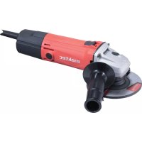
| Product Type | Angle Grinder |
| Brand | Maktec |
| Model | MT963 |
| Wheel Diameter | 125 mm |
| Arbor Thread | M14 x 2 |
| No Load Speed | 11,000 min⁻¹ |
| Overall Length | 270 mm |
| Net Weight | 1.9 kg |
| Power Supply | Single-phase alternating current, voltage per nameplate (generally 230 V ~ 50 Hz) |
| Double Insulation | Yes (Safety Class II) |
| Applications | Grinding, sanding and cutting of metals and construction materials (without water use) |
| Protection | Adjustable wheel guard for protection against sparks and contact |
| Shaft Lock | Yes, for easy accessory changes |
| Switch | Slide switch with lock-on function |
| Side Handle | Yes, screw-on side for better grip |
| Sound Pressure Level | 84 dB(A) (uncertainty K=3 dB(A)) |
| Vibration Emission (grinding) | 6.5 m/s² (uncertainty K=1.5 m/s²) |
| Vibration Emission (sanding) | 3.0 m/s² (uncertainty K=1.5 m/s²) |
| Carbon Brush Replacement | Carbon brushes accessible by plugs, replace in pairs when they reach the wear line |
| Cleaning | Regularly clean ventilation slots with a non-metallic object after unplugging |
| Included Accessories | Lock nut wrench, side handle, wheel guard, inner flange, lock nut |
Frequently Asked Questions - MT963 Maktec
User questions about MT963 Maktec
0 question about this device. Answer the ones you know or ask your own.
Ask a new question about this device
Download the instructions for your Grinder in PDF format for free! Find your manual MT963 - Maktec and take your electronic device back in hand. On this page are published all the documents necessary for the use of your device. MT963 by Maktec.
USER MANUAL MT963 Maktec
Explanation of general view
1 P r e s s
2 Slide switch lever
3 Wheel guard
4 S c r e w
5 Bearing box
6 Lock nut
7 Depressed center grinding wheel/ Multi-disc
8 Inner flange
9 Lock nut wrench
10 Shaft lock
11 Abrasive cut-off wheel/diamond wheel
12 Wheel guard for abrasive cut-off wheel/diamond wheel
13 Limit mark
14 Brush holder cap
15 Screwdriver
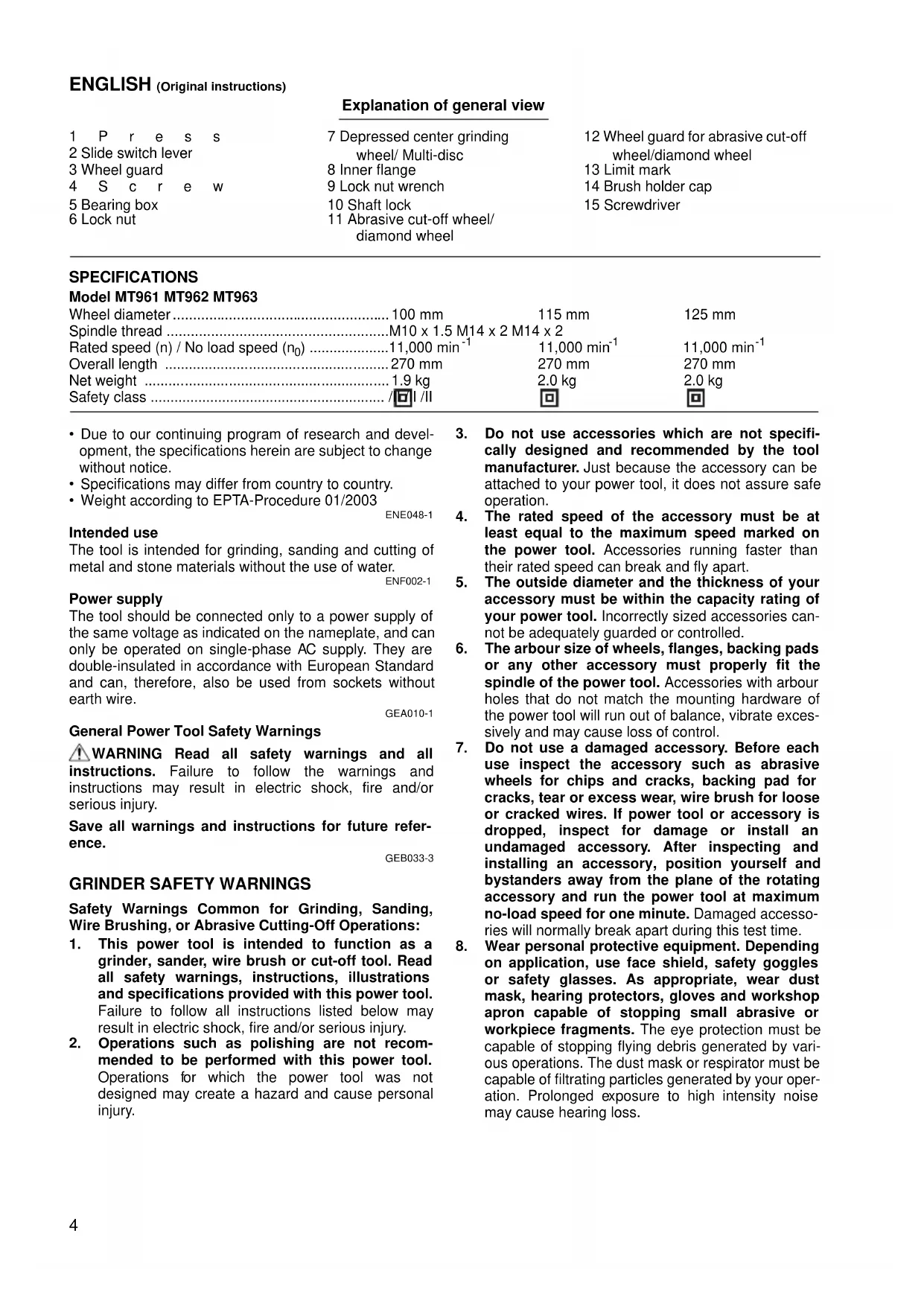
SPECIFICATIONS
Model MT961 MT962 MT963
| Wheel diameter | 100 mm | 115 mm | 125 mm |
| Spindle thread | M10 x 1.5 M14 x 2 M14 x 2 | ||
| Rated speed (n) / No load speed (n0) | 11,000 min-1 | 11,000 min-1 | 11,000 min-1 |
| Overall length | 270 mm | 270 mm | 270 mm |
| Net weight | 1.9 kg | 2.0 kg | 2.0 kg |
| Safety class | /II /II | 回 | 回 |
- Due to our continuing program of research and development, the specifications herein are subject to change without notice.
- Specifications may differ from country to country.
Weight according to EPTA-Procedure 01/2003
ENE048-1
Intended use
The tool is intended for grinding, sanding and cutting of metal and stone materials without the use of water.
ENF002-1
Power supply
The tool should be connected only to a power supply of the same voltage as indicated on the nameplate, and can only be operated on single-phase AC supply. They are double-insulated in accordance with European Standard and can, therefore, also be used from sockets without earth wire.
GEA010-1
General Power Tool SafetyWarnings
WARNING Read all safety warnings and all instructions. Failure to follow the warnings and instructions may result in electric shock, fire and/or serious injury.
Save all warnings and instructions for future reference.
GEB033-3
GRINDER SAFETY WARNINGS
SafetyWarnings Common for Grinding, Sanding, Wire Brushing, or Abrasive Cutting-Off Operations:
- This power tool is intended to function as a grinder, sander, wire brush or cut-off tool. Read all safety warnings, instructions, illustrations and specifications provided with this power tool. Failure to follow all instructions listed below may result in electric shock, fire and/or serious injury.
-
Operations such as polishing are not recommended to be performed with this power tool. Operations for which the power tool was not designed may create a hazard and cause personal injury.
-
Do not use accessories which are not specifically designed and recommended by the tool manufacturer. Just because the accessory can be attached to your power tool, it does not assure safe operation.
- The rated speed of the accessory must be at least equal to the maximum speed marked on the power tool. Accessories running faster than their rated speed can break and fly apart.
- The outside diameter and the thickness of your accessory must be within the capacity rating of your power tool. Incorrectly sized accessories cannot be adequately guarded or controlled.
- The arbour size of wheels, flanges, backing pads or any other accessory must properly fit the spindle of the power tool. Accessories with arbour holes that do not match the mounting hardware of the power tool will run out of balance, vibrate excessively and may cause loss of control.
- Do not use a damaged accessory. Before each use inspect the accessory such as abrasive wheels for chips and cracks, backing pad for cracks, tear or excess wear, wire brush for loose or cracked wires. If power tool or accessory is dropped, inspect for damage or install an undamaged accessory. After inspecting and installing an accessory, position yourself and bystanders away from the plane of the rotating accessory and run the power tool at maximum no-load speed for one minute. Damaged accessories will normally break apart during this test time.
-
Wear personal protective equipment. Depending on application, use face shield, safety goggles or safety glasses. As appropriate, wear dust mask, hearing protectors, gloves and workshop apron capable of stopping small abrasive or workpiece fragments. The eye protection must be capable of stopping flying debris generated by various operations. The dust mask or respirator must be capable of filtrating particles generated by your operation. Prolonged exposure to high intensity noise may cause hearing loss.
-
Keep bystanders a safe distance away from work area. Anyone entering the work area must wear personal protective equipment. Fragments of workpiece or of a broken accessory may fly away and cause injury beyond immediate area of operation.
- Hold power tool by insulated gripping surfaces only, when performing an operation where the cutting accessory may contact hidden wiring or its own cord. Cutting accessory contacting a "live" wire may make exposed metal parts of the power tool "live" and shock the operator.
- Position the cord clear of the spinning accessory. If you lose control, the cord may be cut or snagged and your hand or arm may be pulled into the spinning accessory.
- Never lay the power tool down until the accessory has come to a complete stop. The spinning accessory may grab the surface and pull the power tool out of your control.
- Do not run the power tool while carrying it at your side. Accidental contact with the spinning accessory could snag your clothing, pulling the accessory into your body.
- Regularly clean the power tool's air vents. The motor's fan will draw the dust inside the housing and excessive accumulation of powdered metal may cause electrical hazards.
- Do not operate the power tool near flammable materials. Sparks could ignite these materials.
- Do not use accessories that require liquid coolants. Using water or other liquid coolants may result in electrocution or shock.
Kickback and RelatedWarnings
Kickback is a sudden reaction to a pinched or snagged rotating wheel, backing pad, brush or any other accessory. Pinching or snagging causes rapid stalling of the rotating accessory which in turn causes the uncontrolled power tool to be forced in the direction opposite of the accessory's rotation at the point of the binding.
For example, if an abrasive wheel is snagged or pinched by the workpiece, the edge of the wheel that is entering into the pinch point can dig into the surface of the material causing the wheel to climb out or kick out. The wheel may either jump toward or away from the operator, depending on direction of the wheel's movement at the point of pinching. Abrasive wheels may also break under these conditions.
Kickback is the result of power tool misuse and/or incorrect operating procedures or conditions and can be avoided by taking proper precautions as given below.
a) Maintain a firm grip on the power tool and position your body and arm to allow you to resist kickback forces. Always use auxiliary handle, if provided, for maximum control over kickback or torque reaction during startup. The operator can control torque reactions or kickback forces, if proper precautions are taken.
b) Never place your hand near the rotating accessory. Accessory may kickback over your hand.
c) Do not position your body in the area where power tool will move if kickback occurs. Kickback will propel the tool in direction opposite to the wheel's movement at the point of snagging.
d) Use special care when working corners, sharp edges etc. Avoid bouncing and snagging the accessory. Corners, sharp edges or bouncing have a tendency to snag the rotating accessory and cause loss of control or kickback.
e) Do not attach a saw chain woodcarving blade or toothed saw blade. Such blades create frequent kickback and loss of control.
SafetyWarnings Specific for Grinding and Abrasive Cutting-Off Operations:
a) Use only wheel types that are recommended for your power tool and the specific guard designed for the selected wheel. Wheels for which the power tool was not designed cannot be adequately guarded and are unsafe.
b) The guard must be securely attached to the power tool and positioned for maximum safety, so the least amount of wheel is exposed towards the operator. The guard helps to protect operator from broken wheel fragments and accidental contact with wheel.
c) Wheels must be used only for recommended applications. For example: do not grind with the side of cut-off wheel. Abrasive cut-off wheels are intended for peripheral grinding, side forces applied to these wheels may cause them to shatter.
d) Always use undamaged wheel flanges that are of correct size and shape for your selected wheel. Proper wheel flanges support the wheel thus reducing the possibility of wheel breakage. Flanges for cut-off wheels may be different from grinding wheel flanges.
e) Do not use worn down wheels from larger power tools. Wheel intended for larger power tool is not suitable for the higher speed of a smaller tool and may burst.
Additional SafetyWarnings Specific for Abrasive Cutting-Off Operations:
a) Do not "jam" the cut-off wheel or apply excessive pressure. Do not attempt to make an excessive depth of cut. Overstressing the wheel increases the loading and susceptibility to twisting or binding of the wheel in the cut and the possibility of kickback or wheel breakage.
b) Do not position your body in line with and behind the rotating wheel. When the wheel, at the point of operation, is moving away from your body, the possible kickback may propel the spinning wheel and the power tool directly at you.
c) When wheel is binding or when interrupting a cut for any reason, switch off the power tool and hold the power tool motionless until the wheel comes to a complete stop. Never attempt to remove the cut-off wheel from the cut while the wheel is in motion otherwise kickback may occur. Investigate and take corrective action to eliminate the cause of wheel binding.
d) Do not restart the cutting operation in the workpiece. Let the wheel reach full speed and carefully reenter the cut. The wheel may bind, walk up or kickback if the power tool is restarted in the workpiece.
e) Support panels or any oversized workpiece to minimize the risk of wheel pinching and kickback. Large workpieces tend to sag under their own weight. Supports must be placed under the workpiece near the line of cut and near the edge of the workpiece on both sides of the wheel.
f) Use extra caution when making a "pocket cut" into existing walls or other blind areas. The protruding wheel may cut gas or water pipes, electrical wiring or objects that can cause kickback.
SafetyWarnings Specific for Sanding Operations:
a) Do not use excessively oversized sanding disc paper. Follow manufacturers recommendations, when selecting sanding paper. Larger sanding paper extending beyond the sanding pad presents a laceration hazard and may cause snagging, tearing of the disc or kickback.
SafetyWarnings Specific for Wire Brushing Operations:
a) Be aware that wire bristles are thrown by the brush even during ordinary operation. Do not overstress the wires by applying excessive load to the brush. The wire bristles can easily penetrate light clothing and/or skin.
b) If the use of a guard is recommended for wire brushing, do not allow interference of the wire wheel or brush with the guard. Wire wheel or brush may expand in diameter due to work load and centrifugal forces.
Additional safety warnings:
- When using depressed center grinding wheels, be sure to use only fiberglass-reinforced wheels.
- Be careful not to damage the spindle, the flange (especially the installing surface) or the lock nut. Damage to these parts could result in wheel breakage.
- Make sure the wheel is not contacting the workpiece before the switch is turned on.
- Before using the tool on an actual workpiece, let it run for a while. Watch for vibration or wobbling that could indicate poor installation or a poorly balanced wheel.
- Use the specified surface of the wheel to perform the grinding.
- Watch out for flying sparks. Hold the tool so that sparks fly away from you and other persons or flammable materials.
- Do not leave the tool running. Operate the tool only when hand-held.
- Do not touch the workpiece immediately after operation; it may be extremely hot and could burn your skin.
- Always be sure that the tool is switched off and unplugged or that the battery cartridge is removed before carrying out any work on the tool.
- Observe the instructions of the manufacturer for correct mounting and use of wheels. Handle and store wheels with care.
- Do not use separate reducing bushings or adaptors to adapt large hole abrasive wheels.
- Use only flanges specified for this tool.
- For tools intended to be fitted with threaded hole wheel, ensure that the thread in the wheel is long enough to accept the spindle length.
- Check that the workpiece is properly supported.
- Pay attention that the wheel continues to rotate after the tool is switched off.
- If working place is extremely hot and humid, or badly polluted by conductive dust, use a short-circuit breaker (30 mA) to assure operator safety.
- Do not use the tool on any materials containing asbestos.
- Do not use water or grinding lubricant.
- Ensure that ventilation openings are kept clear when working in dusty conditions. If it should become necessary to clear dust, first disconnect the tool from the mains supply (use non metallic objects) and avoid damaging internal parts.
- When use cut-off wheel, always work with the dust collecting wheel guard required by domestic regulation.
- Cutting discs must not be subjected to any lateral pressure.
SAVE THESE INSTRUCTIONS.
WARNING:
DO NOT let comfort or familiarity with product (gained from repeated use) replace strict adherence to safety rules for the subject product. MISUSE or failure to follow the safety rules stated in this instruction manual may cause serious personal injury.
FUNCTIONAL DESCRIPTION
CAUTION:
Always be sure that the tool is switched off and unplugged before adjusting or checking function on the tool.
Shaft lock (Fig. 1)
CAUTION:
- Never actuate the shaft lock when the spindle is moving. The tool may be damaged.
Press the shaft lock to prevent spindle rotation when installing or removing accessories.
Switch action (Fig. 2)
CAUTION:
- Before plugging in the tool, always check to see that the slide switch actuates properly and returns to the "OFF" position when the rear of the slide switch is depressed.
- Switch can be locked in "ON" position for ease of operator comfort during extended use. Apply caution when locking tool in "ON" position and maintain firm grasp on tool.
To start the tool, slide the switch lever toward the "I (ON)" position. For continuous operation, press the front of the switch lever to lock it.
To stop the tool, press the rear of the switch lever, then slide it toward the "O (OFF)" position.
ASSEMBLY
CAUTION:
- Always be sure that the tool is switched off and unplugged before carrying out any work on the tool.
Installing side grip (handle) (Fig. 3)
CAUTION:
- Always be sure that the side grip is installed securely before operation.
Screw the side grip securely on the position of the tool as shown in the figure.
Installing or removing wheel guard (For depressed center wheel, multi disc / abrasive cut-off wheel, diamond wheel) (Fig. 4)
CAUTION:
- The wheel guard must be fitted on the tool so that the closed side of the guard always points toward the operator.
Mount the wheel guard with the protrusion on the wheel guard band aligned with the notch on the bearing box. Then rotate the wheel guard to such an angle that it can protect the operator according to work. Be sure to tighten the screw securely.
To remove wheel guard, follow the installation procedure in reverse.
Installing or removing depressed center grinding wheel/Multi-disc
WARNING:
- Always use supplied guard when depressed center grinding wheel/Multi-disc is on tool. Wheel can shatter during use and guard helps to reduce chances of personal injury.
Mount the inner flange onto the spindle. Fit the wheel/disc on the inner flange and screw the lock nut onto the spindle. (Fig. 5)
To tighten the lock nut, press the shaft lock firmly so that the spindle cannot revolve, then use the lock nut wrench and securely tighten clockwise.
To remove the wheel, follow the installation procedure in reverse. (Fig. 6)
WARNING:
- Only actuate the shaft lock when the spindle is not moving.
OPERATION
WARNING:
- It should never be necessary to force the tool. The weight of the tool applies adequate pressure. Forcing and excessive pressure could cause dangerous wheel breakage.
- ALWAYS replace wheel if tool is dropped while grinding.
- NEVER bang or hit grinding disc or wheel onto work.
- Avoid bouncing and snagging the wheel, especially when working corners, sharp edges etc. This can cause loss of control and kickback.
- NEVER use tool with wood cutting blades and other saw blades. Such blades when used on a grinder frequently kick and cause loss of control leading to personal injury.
CAUTION:
After operation, always switch off the tool and wait until the wheel has come to a complete stop before putting the tool down.
Grinding and sanding operation (Fig. 7)
ALWAYS hold the tool firmly with one hand on housing and the other on the side handle. Turn the tool on and then apply the wheel or disc to the workpiece. In general, keep the edge of the wheel or disc at an angle of about 15 degrees to the workpiece surface.
During the break-in period with a new wheel, do not work the grinder in the B direction or it will cut into the workpiece. Once the edge of the wheel has been rounded off by use, the wheel may be worked in both A and B direction.
Operation with abrasive cut-off / diamond wheel (optional accessory) (Fig. 8) The direction for mounting the lock nut and the inner flange varies by wheel thickness. Refer to the table below.
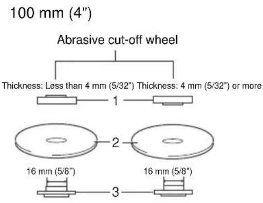
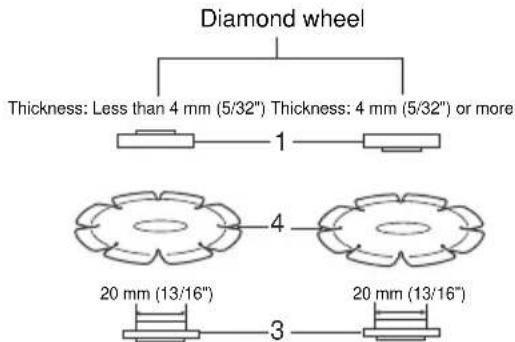
1. Lock nut 2. Abrasive cut-off wheel 3. Inner flange 4. Diamond wheel
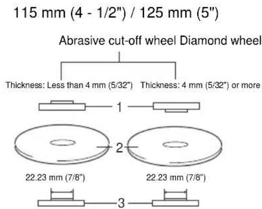
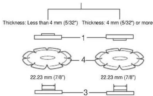
1. Lock nut 2. Abrasive cut-off wheel 3. Inner flange 4. Diamond wheel
WARNING:
- When using an abrasive cut-off / diamond wheel, be sure to use only the special wheel guard designed for use with cut-off wheels.
- NEVER use cut-off wheel for side grinding.
- Do not "jam" the wheel or apply excessive pressure. Do not attempt to make an excessive depth of cut. Overstressing the wheel increases the loading and susceptibility to twisting or binding of the wheel in the cut and the possibility of kickback, wheel breakage and overheating of the motor may occur.
- Do not start the cutting operation in the workpiece. Let the wheel reach full speed and carefully enter into the cut moving the tool forward over the workpiece surface. The wheel may bind, walk up or kickback if the power tool is started in the workpiece.
- During cutting operations, never change the angle of the wheel. Placing side pressure on the cut-off wheel (as in grinding) will cause the wheel to crack and break, causing serious personal injury.
- A diamond wheel shall be operated perpendicular to the material being cut.
MAINTENANCE
CAUTION:
Always be sure that the tool is switched off and unplugged before attempting to perform inspection or maintenance.
- Never use gasoline, benzine, thinner, alcohol or the like. Discoloration, deformation or cracks may result.
Replacing carbon brushes (Fig. 9 & 10)
Remove and check the carbon brushes regularly. Replace when they wear down to the limit mark. Keep the carbon brushes clean and free to slip in the holders. Both carbon brushes should be replaced at the same time. Use only identical carbon brushes.
Use a screwdriver to remove the brush holder caps. Take out the worn carbon brushes, insert the new ones and secure the brush holder caps.
To maintain product SAFETY and RELIABILITY, repairs, any other maintenance or adjustment should be performed by Makita Authorized Service Centers, always using Makita replacement parts.
Noise
The typical A-weighted noise level determined according to EN60745:
For Model MT961
Sound pressure level (L_pA) : 82 dB (A)
Sound power level (L_WA) : 93 dB (A)
Uncertainty (K): 3 dB (A)
For Model MT962
Sound pressure level (L_pA) : 83 dB (A)
Sound power level (L_WA) : 94 dB (A)
Uncertainty (K): 3 dB (A)
For Model MT963
Sound pressure level (L_pA) : 84 dB (A)
Sound power level (LwA): 95 dB (A)
Uncertainty (K): 3 dB (A)
Wear ear protection
ENG900-1
Vibration
The vibration total value (tri-axial vector sum) determined according to EN60745:
Model MT961
Work mode: surface grinding
Vibration emission (a_h,AG) .. 5.5m / s^2
Uncertainty (K): 1.5m / s^2
If the tool is used for other applications, the vibration values may be different.
Work mode: disc sanding
Vibration emission (a_h,DS) .. 2.5m / s^2 or less
Uncertainty (K): 1.5m / s^2
If the tool is used for other applications, the vibration emission value may be different.
Model MT962
Work mode: surface grinding
If the tool is used for other applications, the vibration values may be different.
Work mode: disc sanding
Vibration emission (a_h,DS) : 2.5m / s^2
Uncertainty (K): 1.5m / s^2
If the tool is used for other applications, the vibration emission value may be different.
Model MT963
Work mode: surface grinding
Vibration emission (a_h,AG) .. 6.5m / s^2
Uncertainty (K): 1.5m / s^2
If the tool is used for other applications, the vibration values may be different.
Work mode: disc sanding
Vibration emission (a_h,DS) : 3.0m / s^2
Uncertainty (K): 1.5m / s^2
If the tool is used for other applications, the vibration emission value may be different.
- The declared vibration emission value has been measured in accordance with the standard test method and may be used for comparing one tool with another.
- The declared vibration emission value may also be used in a preliminary assessment of exposure.
- The declared vibration emission value is used for main applications of the power tool. However if the power tool is used for other applications, the vibration emission value may be different.
WARNING: - The vibration emission during actual use of the power tool can differ from the declared emission value depending on the ways in which the tool is used.
- Be sure to identify safety measures to protect the operator that are based on an estimation of exposure in the actual conditions of use (taking account of all parts of the operating cycle such as the times when the tool is switched off and when it is running idle in addition to the trigger time).
ENH101-14
For European countries only
EC Declaration of Conformity
We Makita Corporation as the responsible manufacturer declare that the following Makita machine(s):
Designation of Machine: Angle Grinding
Model No./Type:MT961,MT962,MT963
are of series production and
Conforms to the following European Directives: 2006/42/EC
And are manufactured in accordance with the following standards or standardised documents: EN60745
The technical documentation is kept by our authorized representative in Europe who is:
Makita International Europe Ltd.
Michigan Drive, Tongwell,
Milton Keynes, MK15 8JD, England
11.11.2009

Tomoyasu Kato
Director
Makita Corporation
3-11-8, Sumiyoshi-cho,
Anjo, Aichi, JAPAN
Descriptif
Michigan Drive, Tongwell,
Milton Keynes, MK15 8JD, Angleterre
11.11.2009
3-11-8, Sumiyoshi-cho,
Anjo, Aichi, JAPAN
Übersicht
Michigan Drive, Tongwell,
Milton Keynes, MK15 8JD, England
11.11.2009

Tomoyasu Kato Direktor
Makita Corporation
3-11-8, Sumiyoshi-cho,
Anjo, Aichi, JAPAN
Visione generale
Michigan Drive, Tongwell,
Milton Keynes, MK15 8JD, England
11.11.2009

Tomoyasu Kato
Aministratore
Makita Corporation
3-11-8, Sumiyoshi-cho,
Anjo, Aichi, JAPAN
Michigan Drive, Tongwell,
Milton Keynes, MK15 8JD, England
11.11.2009

Tomoyasu Kato
Directeur
Makita Corporation
3-11-8, Sumiyoshi-cho,
Anjo, Aichi, JAPAN
Michigan Drive, Tongwell,
Milton Keynes, MK15 8JD, Inglaterra
11.11.2009

Tomoyasu Kato
Director
Makita Corporation
3-11-8, Sumiyoshi-cho,
Anjo, Aichi, JAPAN
Explicaçao geral
Michigan Drive, Tongwell,
Milton Keynes, MK15 8JD, Inglaterra
11.11.2009

Tomoyasu Kato Director
Makita Corporation
3-11-8, Sumiyoshi-cho,
Anjo, Aichi, JAPAN
Michigan Drive, Tongwell,
Milton Keynes, MK15 8JD, England
11.11.2009

3-11-8, Sumiyoshi-cho,
Anjo, Aichi, JAPAN
Michigan Drive, Tongwell,
Milton Keynes, MK15 8JD, England (Ayyia)
11.11.2009

Tomoyasu Kato
△ieuθuvtnC
Makita Corporation
3-11-8, Sumiyoshi-cho,
Anjo, Aichi, JAPAN
Makita Corporation
Anjo, Aichi, Japan
884966A997
www.makita.com