
DWM312 - Router D-LINK - Free user manual and instructions
Find the device manual for free DWM312 D-LINK in PDF.
| Brand | D-Link |
| Model | DWM312 |
| Product Type | 4G LTE M2M Router |
| Network Interfaces | 1 RJ-45 Ethernet port 10/100 Mbps, 2 SMA connectors for external antennas, 2 micro-SIM slots |
| Supported Mobile Standards | 4G LTE, 3G/2G |
| Antennas | 2 interchangeable blade antennas (SMA) |
| Power Supply | Input 5 V/2 A to 18 V/0.7 A (AC adapter included, 10 W min recommended) |
| LED Indicators | Power (green), Internet (green), Network (green/blue steady or blinking), Signal (green/orange/red) |
| Management | Web user interface (HTTP), SNMP, D-View compatible |
| Security | Install in a cool, dry place, avoid electromagnetic sources, wall mountable |
| Package Contents | Router, AC adapter, RJ-45 cable, 2 blade antennas, quick installation guide, warranty card |
| Default Configuration | IP address: 192.168.0.1, subnet mask: 255.255.255.0, username: admin, password: admin |
| Reset | Press and hold the Reset button for 3 seconds |
| Wall Mounting | Yes, wall mounting brackets included (template screws 8) |
| Maintenance | Clean with a dry, non-abrasive cloth; do not use chemical products |
Frequently Asked Questions - DWM312 D-LINK
User questions about DWM312 D-LINK
0 question about this device. Answer the ones you know or ask your own.
Ask a new question about this device
Download the instructions for your Router in PDF format for free! Find your manual DWM312 - D-LINK and take your electronic device back in hand. On this page are published all the documents necessary for the use of your device. DWM312 by D-LINK.
USER MANUAL DWM312 D-LINK
Quick Installation Guide 4G LTE M2M Router
This document will guide you through the basic installation process for your new D-Link 4G LTE M2M Router.
DWM-312
QUICK INSTALLATION GUIDE
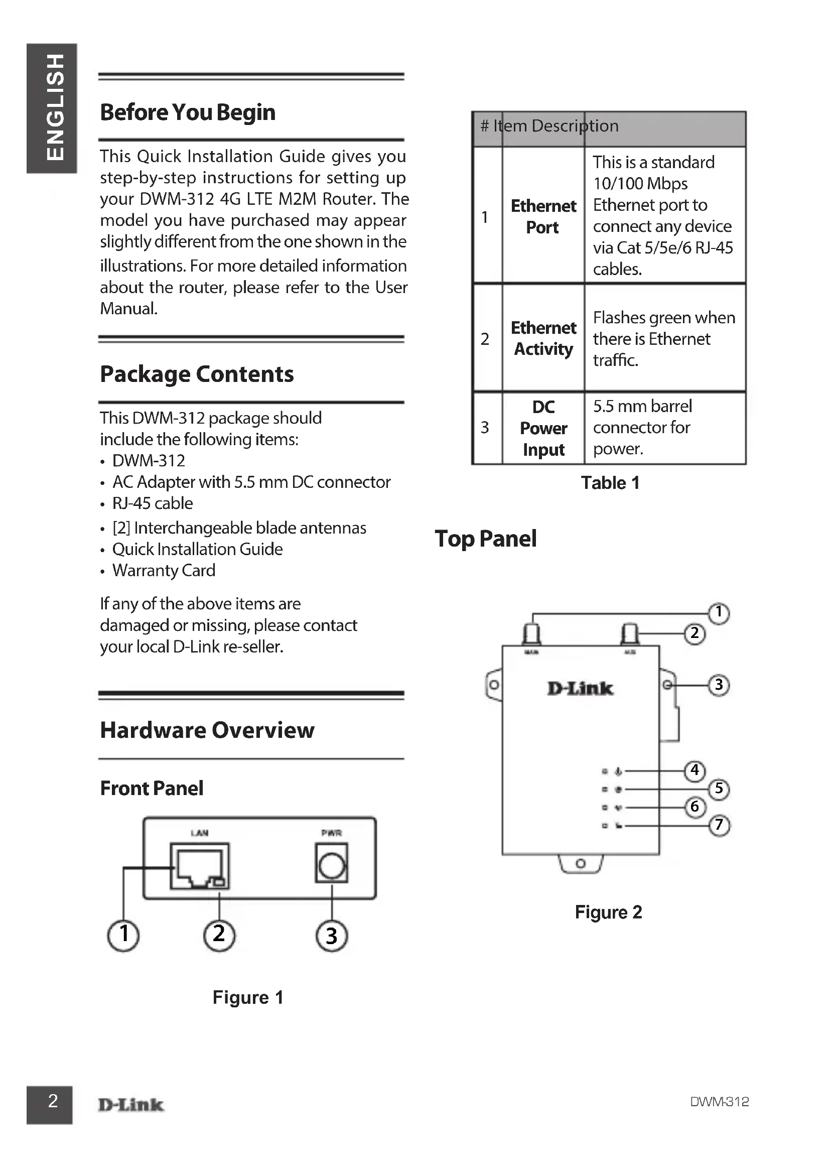
This Quick Installation Guide gives you step-by-step instructions for setting up your DWM-312 4G LTE M2M Router. The model you have purchased may appear slightly different from the one shown in the illustrations. For more detailed information about the router, please refer to the User Manual.
Package Contents
This DWM-312 package should include the following items:
DWM-312
- AC Adapter with 5.5mm DC connector
- RJ-45 cable
[2] Interchangeable blade antennas
- Quick Installation Guide
Warranty Card
If any of the above items are damaged or missing, please contact your local D-Link re-seller.
Hardware Overview
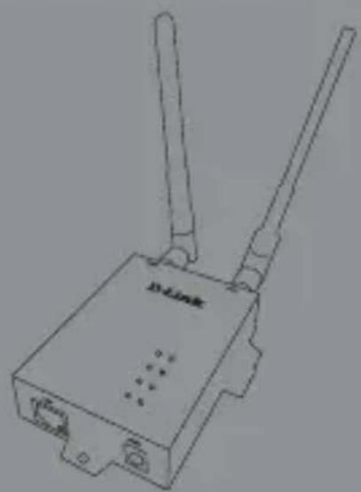
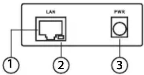
Front Panel
Figure 1
Table 1
| # Item Description | ||
| 1 | Ethernet Port | This is a standard 10/100 Mbps Ethernet port to connect any device via Cat 5/5e/6 RJ-45 cables. |
| 2 | Ethernet Activity | Flashes green when there is Ethernet traffic. |
| 3 | DC Power Input | 5.5 mm barrel connector for power. |
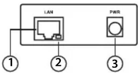
Top Panel
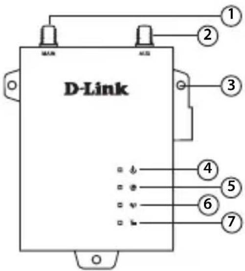
Figure 2
| # Item Description | |||
| 1 | SMA Connector Main1 | SMA female connector - Primary antenna. | |
| 2 | SMA Connector AUX1 | SMA female connector -Auxiliary Antenna. | |
| 3 | Wall Mounts | Wall mounts for standard 8 gauge (4 mm) screws. | |
| 4 Power | A green LED indicates the DWM-312 is receiving power. | ||
| 5 Internet | A green LED indicates Internet connectivity. | ||
| 6 Network | Solid Green | Connected to SIM A LTE Network. | |
| Flashing Green | Fallback to SIM A 3G/2G network. | ||
| Solid Blue | Connected to SIM B LTE Network. | ||
| Flashing Blue | Fallback to SIM B 3G/2G network. | ||
| Off | No Service/SIM Error/APN Error. | ||
| 7 Signal | Green | Indicates strong signal. | |
| Amber | Indicates fair signal. | ||
| Red | Indicates weak signal. | ||
| Off | Indicates no signal. | ||
1 Included antennas are interchangeable, but third party antennas may not be.
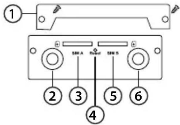
Rear Panel
Figure 3
Table 2
| # Item Description | ||
| 1 | Security Plate | Security plate covering the SIM card slots containing two screw holes |
| 2 | SMA Connector AUX¹ | SMA female connector - Auxiliary Antenna |
| 3 | SIM A Primary SIM card | |
| 4 | Reset | Press and hold for 3 seconds to reset |
| 5 | SIM B Secondary SIM card | |
| 6 | SMA Connector Main¹ | SMA female connector - Primary antenna |
1 Included antennas are interchangeable, but third party antennas may not be.
Table 3: Back Panel
Hardware Installation
Before You Begin
Observe the following precautions to help prevent shutdowns, equipment failures, and personal injury:
- Install the DWM-312 in a cool and dry place. Refer to the technical specifications in the user manual for the acceptable operating temperature and humidity ranges.
- Install the router in a site free from strong electromagnetic sources, vibration, dust, excessive moisture, and direct sunlight.
- Place antennas in an unobstructed area with clear mobile signal. Avoid metal boxes, brick walls, and other dense materials. It is recommended to use the web interface to confirm signal strength before permanent installation.
- Visually inspect the power connector and make sure that it is fully secure.
- Do not stack any devices on top of the router.
Installing SIM card(s)
The DWM-312 is equipped with dual-SIM slots. At least one active SIM card with Internet access is required for proper operation.
- Unscrew two screws to remove the security plate and get access to SIM card slots
- Insert a micro-SIM card into the slot labelled SIMA with the contacts facing down. If you wish to install a second SIM card, insert it into the slot labelled SIMB.
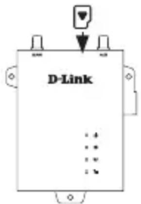
Figure 4: Installing a micro-SIM card
- Gently press the micro-SIM into the slot until it locks into place. To remove, press again and the SIM card will be ejected.
- Screw the security plate back on using the two screws removed earlier in order to protect the SIM card slots.
Note: SIM behavior must be configured from the web UI before an Internet connection can be established.
Attach the External Antennas
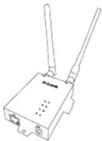
Figure 5: Attaching External Antennas
The DWM-312 requires two external antennas to function correctly. The included antennas are interchangeable, but third party antennas may require connection to specific ports.
- Attach the antennas to the SMA connectors on the back of the router to the ports labelled "Main" and "Aux." Turn clockwise to fasten the antenna.
- Place antennas where they will receive optimal signal. Arrange them so they point upward.
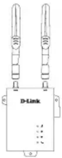
Figure 6: Attaching Antenna to Modem
Note: The included antennas are interchangeable. Third party antennas may require connection to specific ports.
Powering the Router
The router features a flexible power input ranging from 5 volts/2 amps to 18 volts/0.7 amps. A minimum of 10 watts total power is recommended.
Using the Included AC Adapter
- Attach the barrel connector of included AC adapter to the DWM-312 power port on the front panel.
- Attach the AC adapter to an appropriate AC socket.
Connecting Devices
After the DWM-312 has been successfully installed, the router can be connected to the end device via the following connection method:
Over Ethernet
The Ethernet port can be connected to an end device. Use a standard Category 5/5e/6 RJ-45 Ethernet cable to connect the end device to the
router. The port will auto-negotiate to the highest possible port speed based on the connected device. Note that the DWM-312 supports a maximum transfer speed of 100 Mbps over Ethernet.
Management Options
Before You Begin
The D-Link router can be managed by using the Web User Interface (Web UI), or Simple Network Management Protocol (SNMP) management interfaces. If you wish to manage a single D-Link router, the Web UI may be the best option.
Each router must be assigned its own IP address, which is used for communication with the management PC. Please refer to the following installation instructions to get started with the Web UI and SNMP management interfaces.
Web User Interface
Once the router has been successfully installed, you can begin configuration, monitor the LED panel, and display graphical statistics using a web browser. Supported browsers include: Microsoft Internet Explorer, Firefox, Chrome, and Safari.
You need the following equipment to access the Web UI of your device:
- A PC with a RJ-45 Ethernet port
-
A standard Ethernet cable
-
Connect the Ethernet cable to the router's Ethernet port and to the Ethernet port on the PC.
- Configure the PC's IP address to be in the network segment as the router. The router's default IP address is 192.168.0.1, with subnet mask 255.255.255.0.
- For example, to connect to the router using the default settings, your PC should have an IP address in the range: 192.168.0.2-.254 and a subnet mask of 255.255.255.0.
- Open the web browser and enter http://192.168.0.1/in the address box.
- Log in to the router. The default username is admin and the default password is admin.
SNMP
You can manage the router with D-Link D-View, or any other SNMP-compatible program. The SNMP function is disabled by default and must be enabled on the router first by using the Web UI, as described in the previous section. The D-View SNMP Network Management System is a comprehensive standard-based management tool designed to centrally manage critical network infrastructure. D-View provides useful tools to allow network administrators to effectively manage device configurations, fault tolerance, performance, and security.
D-Link offers a free version of D-View which can allow you to manage up to 25 devices. You can download or get more information on the following website: http://dview.dlink.com/.
Additional Information
If you are encountering problems setting up your network, please refer to the user manual.
It contains much more detailed information to get you up and running with your network.
Additional help is available through our offices listed at the back of the user manual or online. To find out more about D-Link products or marketing information, please visit the D-Link website at: http://www.dlink.com/.
TECHNICAL SUPPORT
dlink.com/support
Panel frontal
Figure 1
Table 1
Existe ahora adicional disponible a工程技术 de la comparación, que se han existado para un tiempo. En el presente, el principal component of this application is the D-link. This application has been developed to allow for comparisons between two products. The D-link is a link that is used to compare the performance of two products. It is possible to use this link to compare the performance of two products.
ASISTENCIA TECNICA
dlink.com/support