Axia Isola - Basket FABER - Free user manual and instructions
Find the device manual for free Axia Isola FABER in PDF.
Frequently Asked Questions - Axia Isola FABER
User questions about Axia Isola FABER
0 question about this device. Answer the ones you know or ask your own.
Ask a new question about this device
Download the instructions for your Basket in PDF format for free! Find your manual Axia Isola - FABER and take your electronic device back in hand. On this page are published all the documents necessary for the use of your device. Axia Isola by FABER.
USER MANUAL Axia Isola FABER
natural_image
Simple line drawing of a cylindrical object with a flat top, placed on a base (no text or symbols)Axia Isola
Island Mount Canopy Rangehood
• Installation Instructions
• Use and Care Information
READ AND SAVE THESE INSTRUCTIONS
The Installer must leave these instructions with the homeowner. The homeowner must keep these instructions for future reference and for local electrical inspectors' use.
READ THESE INSTRUCTIONS BEFORE YOU START INSTALLING THIS RANGEHOOD
WARNING: - TO REDUCE THE RISK OF A RANGE TOP GREASE FIRE: a) Never leave surface units unattended at high settings. Boilovers cause smoking and greasy spillovers that may ignite. Heat oils slowly on low or medium setting. b) Always turn hood ON when cooking at high heat or when flambeing food (i.e. Crepes Suzette, Cherries Jubilee, Peppercorn Beef Flambé). c) Clean ventilating fans frequently. Grease should not be allowed to accumulate on fan or filter. d) Use proper pan size. Always use cookware appropriate for the size of the surface element.
WARNING: - TO REDUCE THE RISK OF INJURY TO PERSONS IN THE EVENT OF A RANGE TOP GREASE FIRE, OBSERVE THE FOLLOWING: SMOTHER FLAMES with a close-fitting lid, cookie sheet, or metal tray, then turn off the burner. BE CAREFUL TO PREVENT BURNS. If the flames do not go out immediately EVACUATE AND CALL THE FIRE DEPARTMENT. NEVER PICK UP A FLAMING PAN - You may be burned. DO NOT USE WATER, including wet dishcloths or towels - a violent steam explosion will result. Use an extinguisher ONLY if: 1. You know you have a Class ABC extinguisher, and you already know how to operate it. 2. The fire is small and contained in the area where it started. 3. The fire department is being called. 4. You can fight the fire with your back to an exit.
ALL WALL AND FLOOR OPENINGS WHERE THE RANGEHOOD IS INSTALLED MUST BE SEALED.
This rangehood requires at least 24" of clearance between the bottom of the rangehood and the cooking surface or countertop. This minimum clearance may be higher depending on local building code. For example, for gas ranges, a minimum of 30" may be required. The maximum depth of overhead cabinets is 13". Overhead cabinets on both sides of this unit must be a minimum of 18" above the cooking surface or countertop. Consult the cooktop or range installation instructions given by the manufacturer before making any cutouts. MOBILE HOME INSTALLATION The installation of this rangehood must conform to the Manufactured Home Construction and Safety Standards, Title 24 CFR, Part 3280 (formerly Federal Standard for Mobile Home Construction and Safety, Title 24, HUD, Part 280). Four wire power supply must be used and the appliance wiring must be revised. See Electrical Requirements.
LISEZ BIEN CETTE FICHE AVANT D'INSTALLER LA HOTTE
Determine which venting method is best for your application. Ductwork can extend either through the wall or the roof.
The length of the ductwork and the number of elbows should be kept to a minimum to provide efficient performance. The size of the ductwork should be uniform. Do not install two elbows together. Use duct tape to seal all joints in the ductwork system. Use caulking to seal exterior wall or floor opening around the cap.
Flexible ductwork is not recommended. Flexible ductwork creates back pressure and air turbulence that greatly reduces performance.
Make sure there is proper clearance within the wall or floor for exhaust duct before making cutouts. Do not cut a joist or stud unless absolutely necessary. If a joist or stud must be cut, then a supporting frame must be constructed.
FOR MORE SPECIFIC DUCTWORK INFORMATION, GO TO PAGE 4.
WARNING - To Reduce The Risk Of Fire, Use Only Metal Ductwork.
Cold Weather installations
An additional back draft damper should be installed to minimize backward cold air flow and a nonmetallic thermal break should be installed to minimize conduction of outside temperatures as part of the vent system. The damper should be on the cold air side of the thermal break. The break should be as close as possible to where the vent system enters the heated portion of the house.

WARNING
- Venting system MUST terminate outside the home.
- DO NOT terminate the ductwork in an attic or other enclosed space.
- DO NOT use 4" laundry-type wall caps.
- Flexible-type ductwork is not recommended.
- DO NOT obstruct the flow of combustion and ventilation air.
- Failure to follow venting requirements may result in a fire.
ELECTRICAL REQUIREMENTS
A 120 volt, 60 Hz AC-only electrical supply is required on a separate 15 amp fused circuit. A time-delay fuse or circuit breaker is recommended. The fuse must be sized per local codes in accordance with the electrical rating of this unit as specified on the serial/rating plate located inside the unit near the field wiring compartment. THIS UNIT MUST BE CONNECTED WITH COPPER WIRE ONLY. Wire sizes must conform to the requirements of the National Electrical Code, ANSI/NFPA 70 - latest edition, and all local codes and ordinances. Wire size and connections must conform with the rating of the appliance. Copies of the standard listed above may be obtained from:
National Fire Protection Association
Batterymarch Park
Quincy, Massachusetts 02269
For residential use only.
This appliance should be connected directly to the fused disconnect (or circuit breaker) through flexible, armored or nonmetallic sheathed copper cable. Allow some slack in the cable so the appliance can be moved if servicing is ever necessary. A UL Listed, 1/2" conduit connector must be provided at each end of the power supply cable (at the appliance and at the junction box).
When making the electrical connection, cut a 1 1/4" hole in the wall. A hole cut through wood must be sanded until smooth. A hole through metal must have a grommet.
WARNING - TO REDUCE THE RISK OF FIRE OR ELECTRIC SHOCK, do not use this fan with any solid-state speed control device.
WARNING - TO REDUCE THE RISK OF FIRE, ELECTRICAL SHOCK, OR INJURY TO PERSONS, OBSERVE THE FOLLOWING: Use this unit only in the manner intended by the manufacturer. If you have any questions, contact the manufacturer.
Before servicing or cleaning unit, switch power off at service panel and lock the service disconnecting means to prevent power from being switched on accidentally. When the service disconnecting means cannot be locked, securely fasten a prominent warning device, such as a tag, to the service panel.
CAUTION: For General Ventilating Use Only. Do Not Use To Exhaust Hazardous or Explosive Materials and Vapors.
WARNING - TO REDUCE THE RISK OF FIRE, ELECTRICAL SHOCK, OR INJURY TO PERSONS, OBSERVE THE FOLLOWING: Installation Work And Electrical Wiring Must Be Done By Qualified Person(s) In Accordance With All Applicable Codes And Standards, Including Fire-Rated Construction.
Sufficient air is needed for proper combustion and exhausting of gases through the flue (chimney) of fuel burning equipment to prevent backdrafting. Follow the heating equipment manufacturer's guideline and safety standards such as those published by the National Fire Protection Association (NFPA), and the American Society for Heating, Refrigeration and Air Conditioning Engineers (ASHRAE), and the local code authorities.
When cutting or drilling into wall or ceiling, do not damage electrical wiring and other hidden utilities.
Ducted fans must always be vented to the outdoors.

WARNING
• Electrical ground is required on this rangehood.
- If cold water pipe is interrupted by plastic, nonmetallic gaskets or other materials, DO NOT use for grounding.
• DO NOT ground to a gas pipe.
- DO NOT have a fuse in the neutral or grounding circuit. A fuse in the neutral or grounding circuit could result in electrical shock.
- Check with a qualified electrician if you are in doubt as to whether the rangehood is properly grounded.
- Failure to follow electrical requirements may result in a fire.
RÈGLEMENTS D'ÉVACUATION
OPTIONAL ACCESSORIES AVAILABLE
• \*Ductless Conversion Kit
For non-vented installations only
* it is highly recommended that professional style cooking always be vented to the outside part # 620000042 - Stainless
- Replacement Charcoal Filter
For non-vented installations only, replace charcoal filter as needed part # 620000041
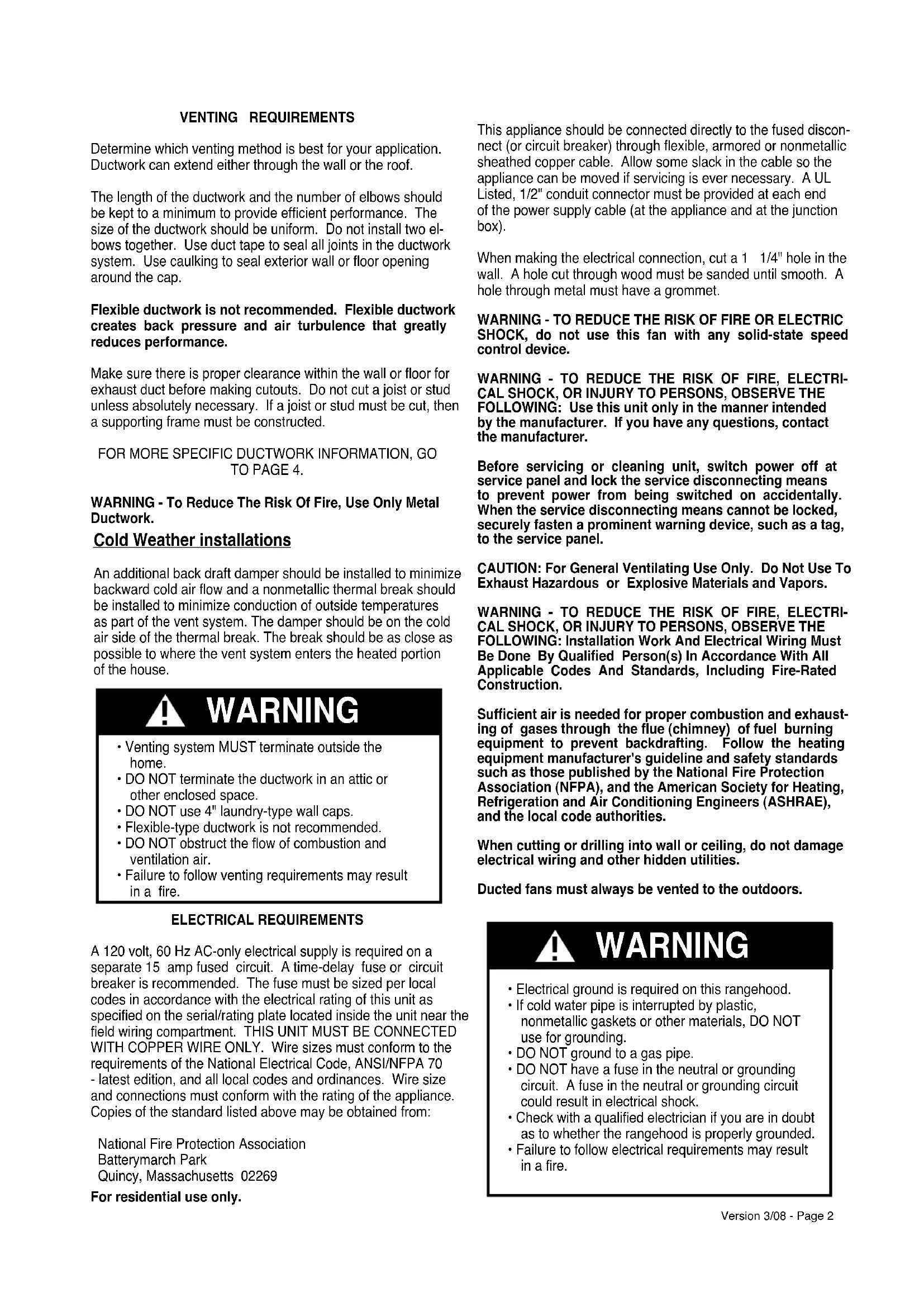
RANGEHOOD COMPONENTS
A. CANOPY SECTION
B. LOWER CHIMNEY COVER
C. UPPER CHIMNEY COVER
D. LOWER CHIMNEY SUPPORT
E. UPPER CHIMNEY SUPPORT
F. CANOPY SCREWS (short screws)
G. DO NOT USE (long screws)
H. WOOD SHELF BOLTS (long bolts)
I. WOOD SHELF WASHERS
J. WOOD SHELF NUTS
K. MOUNTING TEMPLATE
L. DUCT CLAMPS
M. DAMPER
FIGURE 1
chemical
Diagram showing molecular structure with labeled components K, I, H, J, and G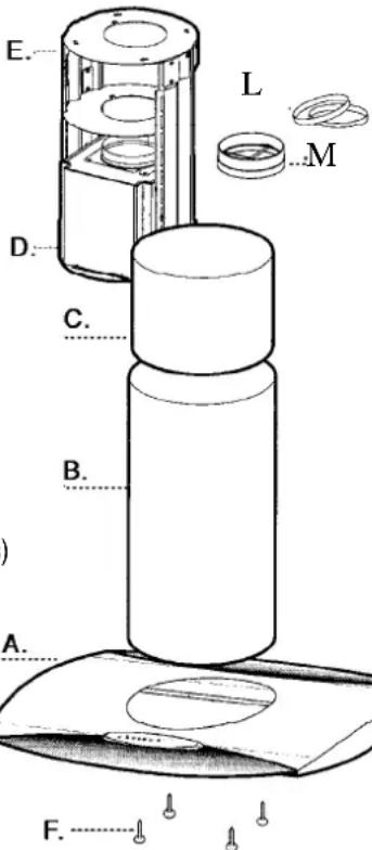
text_image
E. L M D. C. B. A. F.UNPACK THE RANGEHOOD
Remove the rangehood from the carton and place on a flat surface for assembly. Before discarding the packaging, check to make sure that no mounting hardware or parts are missing. DO NOT REMOVE THE PLASTIC COVERING ON THE CHIMNEYS AT THIS TIME! This plastic covering protects the chimney from scratches during installation.
For safe packaging, the entire chimney section of the hood is shipped assembled. It must be disassembled completely for installation. Disassemble packaged chimney components by sliding apart the chimney covers (B and C in FIGURE 1). Remove the UPPER CHIMNEY COVER (C) from the UPPER CHIMNEY SUPPORT (E) by removing the 2 philips screws on the outside top of the chimney cover.
PREPARING TO ATTACH THE CHIMNEY
The rangehood attaches to the ceiling by a metal support structure (D and E in FIGURE 1). This support must be attached to the ceiling before the canopy is attached. This structure must be firmly attached to the ceiling.
FOR WOOD CEILINGS: Use four 4" long wood screws and washers.
FOR PLASTER OR SHEET ROCK CEILINGS:
If possible, the support must be attached to the ceiling joists. If not, a supporting structure behind the sheet rock must be built.
FOR WOOD SHELVES: Use items H, I, & J in FIGURE 1.
CALCULATE THE DUCTRUN LENGTH
The ductrun should not exceed 35 equivalent feet if ducted with the required minimum of 6" round duct. Calculate the length of the ductwork by adding the equivalent feet in FIGURE 2 for each piece of duct in the system. An example is given in FIGURE 3.
For best results, use no more than three 90° elbows. Make sure that there is a minimum of 24" of straight duct between elbows if more than one is used. Do not install two elbows together. If you must elbow right away, do it as far away from the hood's exhaust opening as possible.
| 45° Elbow | 3.0 feet |
| 90° Elbow | 5.0 feet |
| 90° Flat Elbow | 12.0 feet |
| Wall Cap | 0.0 feet |
FIGURE 2
| 9 Feet Straight Duct | 9.0 feet |
| 2 - 90° Elbows | 10.0 feet |
| Wall Cap | 0.0 feet |
| Total System | 19.0 feet |
FIGURE 3
PLAN THE INSTALLATION
This rangehood can be installed as either ducted or ductless. When installed ductless, the rangehood vents out of a grate on the back of the lower chimney. Ductless installations require a Ductless Conversion Kit, available from your dealer.
WARNING! BEFORE MAKING ANY CUTS OR HOLES FOR INSTALLATION, DETERMINE WHICH VENTING METHOD WILL BE USED AND CAREFULLY CALCULATE ALL MEASUREMENTS.
(vented to the outside)
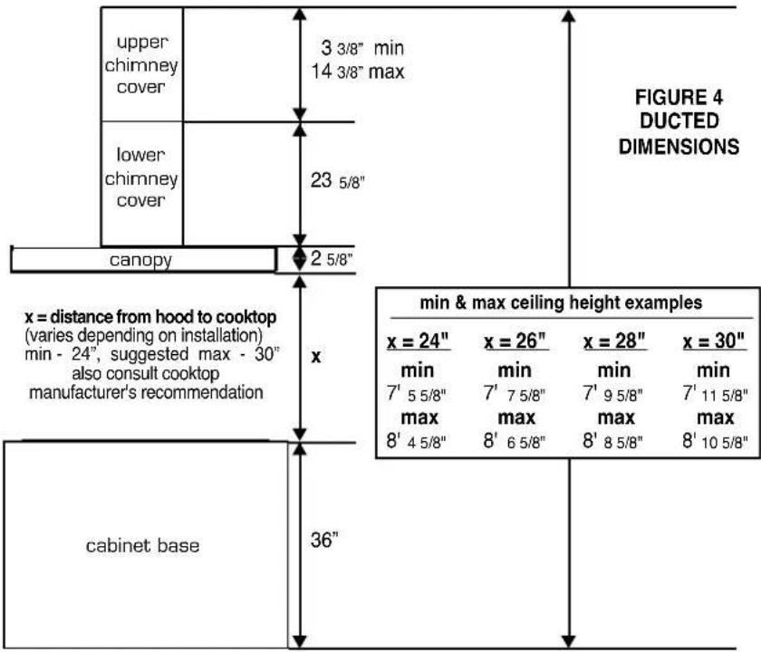
DUCTED INSTALLATION DIMENSIONS
The Axia Isola chimney is highly adjustable and designed to meet varying ceiling heights as indicated in FIGURE 4. The chimney can be adjusted for ceilings between 7' 5 5/8" and 8' 10 5/8" depending on the distance between the bottom of the hood and the cooktop (distance x in FIGURE 4).
text_image
upper chimney cover 3 3/8" min 14 3/8" max lower chimney cover 23 5/8" canopy 2 5/8" FIGURE 4 DUCTED DIMENSIONS x = distance from hood to cooktop (varies depending on installation) min - 24", suggested max - 30" also consult cooktop manufacturer's recommendation cabinet base 36" min & max ceiling height examples x = 24" min 7' 5 5/8" max 8' 4 5/8" x = 26" min 7' 7 5/8" max 8' 6 5/8" x = 28" min 7' 9 5/8" max 8' 8 5/8" x = 30" min 7' 11 5/8" max 8' 10 5/8"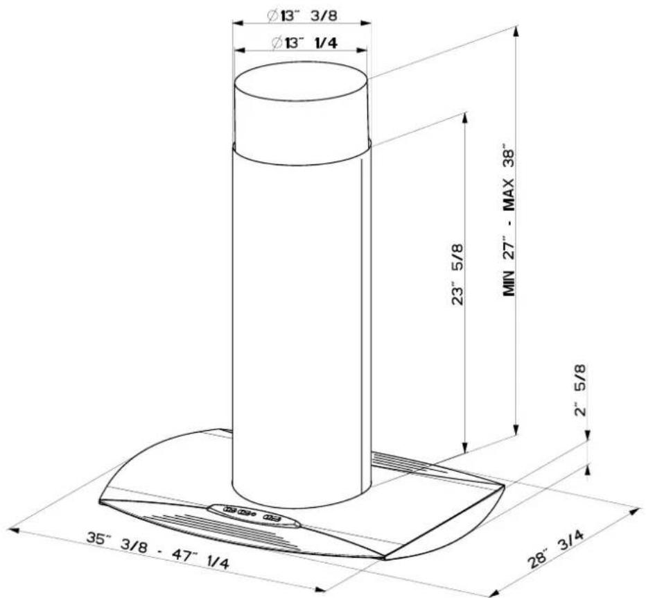
text_image
Ø13" 3/8 Ø13" 1/4 23" 5/8 MIN 27" - MAX 38" 2" 5/8 35" 3/8 - 47" 1/4 28" 3/4WARNING
!
DUE TO THE SIZE AND WEIGHT OF THIS RANGEHOOD, THE SUPPORT MUST BE FIRMLY ATTACHED TO THE CEILING. For plaster or sheet rock ceilings, the support must be attached to the joists. If this is not possible, a support structure must be built behind the plaster or sheet rock. The manufacturer assumes no responsibility for injury or damage caused by improper installations.
PLAN THE INSTALLATION
This rangehood can be installed as either ducted or ductless. When installed ductless, the rangehood vents out of a grate on the back of the lower chimney. Ductless installations require a Ductless Conversion Kit, available from your dealer.
WARNING! BEFORE MAKING ANY CUTS OR HOLES FOR INSTALLATION, DETERMINE WHICH VENTING METHOD WILL BE USED AND CAREFULLY CALCULATE ALL MEASUREMENTS.
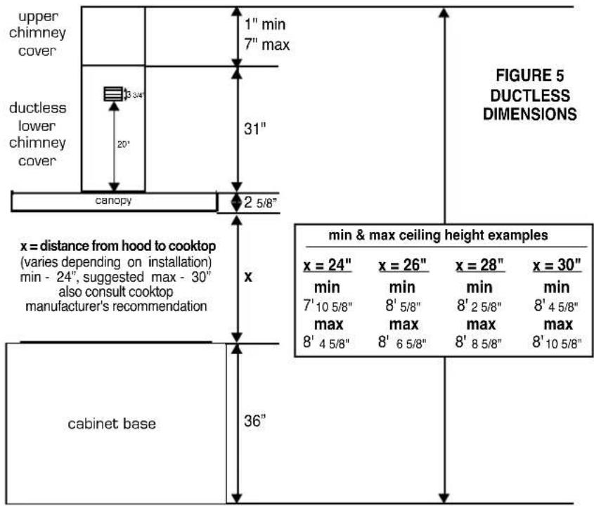
DUCTLESS INSTALLATION DIMENSIONS
(not vented to the outside)
The ductless Axia Isola chimney is adjustable for varying ceiling heights as indicated in FIGURE 5. The chimney can be adjusted for ceilings between 7' 10 5/8" and 8' 10 5/8" depending on the distance between the bottom of the hood and the cooktop (distance x in FIGURE 5).
text_image
upper chimney cover 1" min 7" max ductless lower chimney cover 3 3/4" 20" 31" canopy 2 5/8" FIGURE 5 DUCTLESS DIMENSIONS x = distance from hood to cooktop (varies depending on installation) min - 24", suggested max - 30" also consult cooktop manufacturer's recommendation x cabinet base 36" min & max ceiling height examples x = 24" min 7' 10 5/8" max 8' 4 5/8" x = 26" min 8' 5/8" max 8' 6 5/8" x = 28" min 8' 2 5/8" max 8' 8 5/8" x = 30" min 8' 4 5/8" max 8' 10 5/8"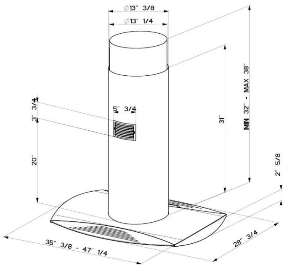
text_image
Ø13" 3/8 Ø13" 1/4 5" 3/4 3" 20" 35" 3/8 - 47" 1/4 31" MIN 32" - MAX 38" 2" 5/8 28" 3/4WARNING

DUE TO THE SIZE AND WEIGHT OF THIS RANGEHOOD, THE SUPPORT MUST BE FIRMLY ATTACHED TO THE CEILING. For plaster or sheet rock ceilings, the support must be attached to the joists. If this is not possible, a support structure must be built behind the plaster or sheet rock. The manufacturer assumes no responsibility for injury or damage caused by improper installations.
ATTACH THE SUPPORT
- Put a thick, protective covering over cooktop, set-in range or countertop to protect from damage or dirt.
- Determine and clearly mark with a pencil on the ceiling where the rangehood will be installed.
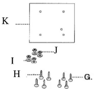
- A template (L in FIGURE 6) for mounting the support is supplied in the carton with the support. Use this template to mark holes for support on the ceiling.
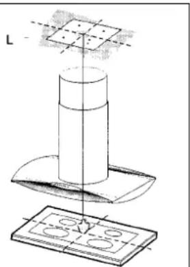
natural_image
Technical line drawing of a mechanical assembly with a cylindrical component and a base plate (no text or symbols)FIGURE 6
- Determine and make necessary cuts for the ductwork. The duct opening is shown on the mounting template (L in FIGURE 6). Install ductwork before mounting the support.
IMPORTANT NOTE: BE CAREFUL WHEN DETERMINING THE LOCATION FOR THE HOLE IN YOUR CEILING FOR THE DUCT WORK. THIS HOLE SHOULD NOT BE CENTERED OVER THE CENTER OF THE COOKING SURFACE AS THE DUCT WORK THAT RUNS UP INSIDE THE CHIMNEY AND THROUGH THE CEILING IS NOT IN THE EXACT CENTER OF THE CHIMNEY.
- Determine the proper location for the Power Supply Cable as E indicated on the template. Use a 1 1/4" Drill Bit to make this hole. Run the Power Supply Cable. Use caulking to seal around the hole. DO NOT turn on the power until installation is complete! A knockout is provided at the top of the UPPER CHIMNEY SUPPORT (E in FIGURE 7).
- For ducted installations, place the round DAMPER (Ain FIGURE 7) into the exhaust opening of the rangehood and press down.
- Before attaching the support to the ceiling, you must determine the desired length of the support structure and adjust the length of the support by removing the eight screws (indicated in FIGURE 7) with a flat head screwdriver. Once the length of the support is determined, install and tighten the eight screws.
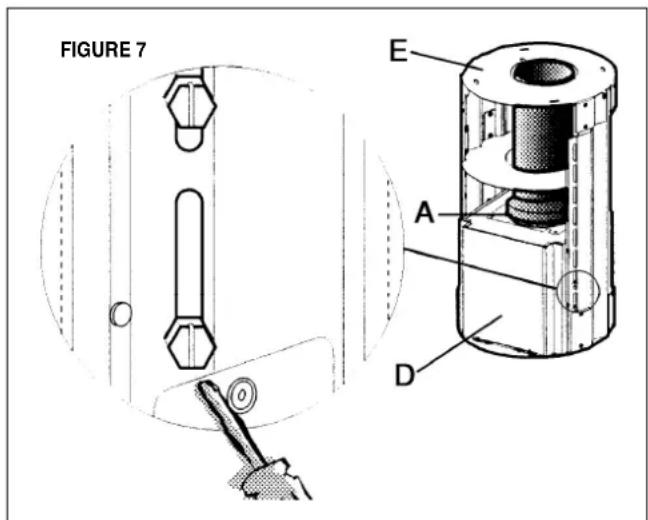
text_image
FIGURE 7 E A D- Slide the UPPER CHIMNEY COVER (C in FIGURE 1 for ducted installations - the upper chimney that came with the rangehood, or G in FIGURE 8 for ductless installations - the upper chimney that came with the ductless kit) down over the UPPER CHIMNEY SUPPORT (E in FIGURE 7) until it rests on the motor box (D in FIGURE 7). Attach the entire support to the ceiling. Make sure that the support is firmly attached to the ceiling.
FOR DUCTLESS INSTALLATIONS
Ductless installations require a Ductless Conversion Kit whose components are pictured in FIGURE 8. Do not use the DAMPER (A in FIGURE 7) for ductless installations. The LOWER CHIMNEY COVER (B in FIGURE 1) should be discarded and replaced by the new one with the hole from the Ductless Conversion Kit (F in FIGURE 8). The UPPER CHIMNEY COVER (C in FIGURE 1) should be discarded and replaced by the shorter one from the Ductless Conversion Kit (G in FIGURE 8).
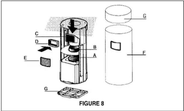
text_image
C D E B A G F G FIGURE 8As indicated in FIGURE 8, place the FLANGE (A) into the exhaust opening of the rangehood and press down. Fit the DUCTLESS DIVERTER EXTENSION VERTICAL (B) over the FLANGE (A) and fit the DUCTLESS DIVERTER (C) over the EXTENSION (B). Fit the DUCTLESS DIVERTER EXTENSION HORIZONTAL (D) into the DIVERTER (C).
MAKE THE ELECTRICAL CONNECTION
Remove the cover from the field wiring compartment. DO NOT turn on the power until installation is complete! Connect the Power Supply Cable to the rangehood. Attach the White lead of the power supply to the White lead of the rangehood with a twist-on type wire connector. Attach the Black lead of the power supply to the Black lead of the rangehood with a twist-on type wire connector. Connect the Green (Green and Yellow) ground wire under the Green grounding screw.
INSTALLING THE RANGEHOOD
- The UPPER CHIMNEY COVER (C in FIGURE 9) attaches using two screws provided (G in FIGURE 9). Slide up and attach the UPPER CHIMNEY COVER.
-
Attach the duct work to the DAMPER (A in FIGURE 7). Make sure to seal all joints with duct tape to prevent leaks.
-
The LOWER CHIMNEY COVER (B in FIGURE 9) rests on the top of the CANOPY SECTION (A in FIGURE 1) once it is installed. Install the LOWER CHIMNEY COVER by sliding it up over the support.
For ductless installations, line up the DUCTLESS DIVERTER EXTENSION HORIZONTAL (D in FIGURE 8) with the hole in the LOWER CHIMNEY COVER (F in FIGURE 8) and snap in the VENT GRID (E in FIGURE 8).

WARNING
DUE TO THE SIZE AND WEIGHT OF THIS RANGE-HOOD, THREE PEOPLE ARE REQUIRED TO INSTALL THE CANOPY. Two people must hold the canopy in place while the third person installs the screws that attach the canopy to the chimney. The manufacturer assumes no responsibility for injury or damage caused by improper installations.
- From below, attach the CANOPY SECTION (A in FIGURE 10) to the assembled chimney support using the four screws provided (F in FIGURE 10).
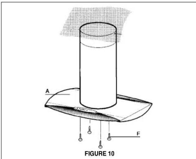
text_image
A F FIGURE 10MAKE THE INTERNAL ELECTRICAL CONNECTIONS
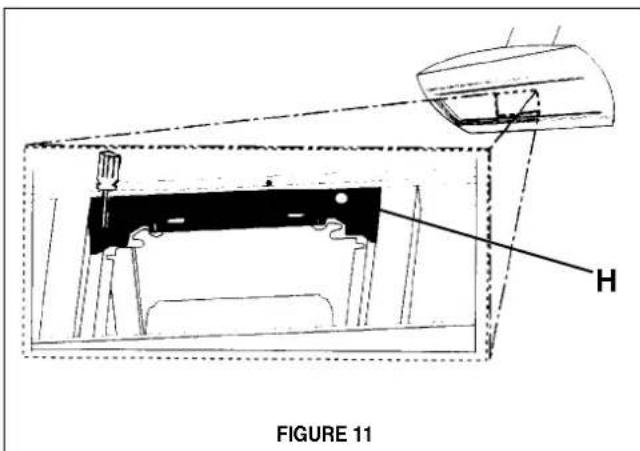
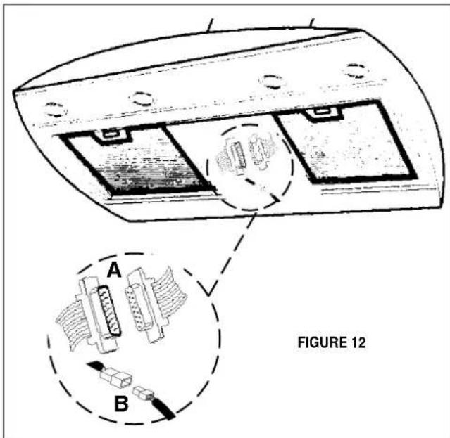
- Remove the metal brackets located on the top and bottom of the underside of the rangehood by removing the screws (FIGURE 11). Removing these brackets provides access to the control and lighting cables which must connect to the control and lighting cables from the inside of the chimney (FIGURE 12).
text_image
FIGURE 11- Run the control cable (A in FIGURE 12) from inside the chimney through the hole (H in FIGURE 11) in the appropriate bracket. Be sure to place the black rubber grommet around the cable inside the hole to protect the cable from being nicked by the metal hole. Connect the control cables together as indicated in FIGURE 12. Tuck them away under the brackets and reinstall the brackets. Repeat this process for the lighting cables (B in FIGURE 12).
text_image
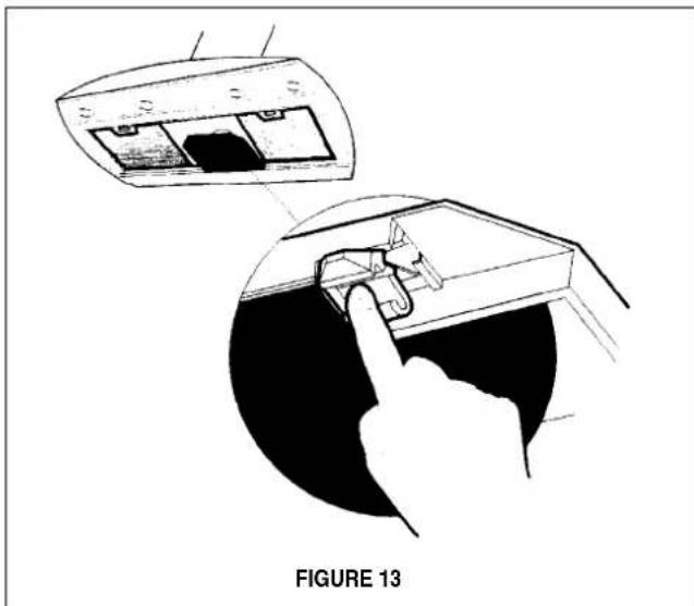
A B FIGURE 12For ductless installations, install the CHARCOAL FILTER (G in FIGURE 8) behind the center grease filter opening by inserting and locking into place.
natural_image
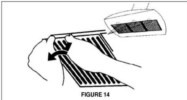
Technical illustration showing a hand inserting a component into a device, with no visible text or symbols.- Install the grease filters using two hands by first pulling and turning the knob to the left so that the locking lever does not protrude from the filter (as in FIGURE 14). Insert the opposite end of the filter into the retaining channel. Insert the knob end next, then turn knob to the right to lock the filter into place.
text_image
FIGURE 14- Turn the power supply on. Turn on blower and lights. If the rangehood does not operate, check that the circuit breaker is not tripped or the house fuse blown. If the unit still does not operate, disconnect the power supply and check that the wiring connections have been made properly.
WIRING DIAGRAM
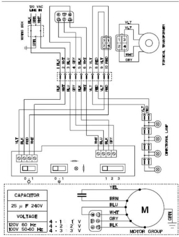
text_image
120 VAC LINE IN WHITE BOX BLK GRN WHT 1 BLK 2 WHT 3 BLU 4 GRY 5 BLK 6 WHT 7 VLT 8 FWD 9 VLT 10 FWD VLT 1 3 2 4 WHT GRY FORUMIAN TRANSPINER VEGETIONAL LAMP VLT RED CLK RED WHT WHT BLU BLK GRY 1 2 3 0 1 0 1 1 2 3 CAPACITOR 25 μF 240V VOLTAGE 120V 60 Hz 100V 50-60 Hz 4 - 1 - 1 V 4 - 2 - 2 V 4 - 3 - 3 V YEL BRN BLU WHT GRY BLK MOTOR GROUP GRN- This rangehood uses 20 watt halogen lamps.
USE AND CARE INFORMATION
This rangehood system is designed to remove smoke, cooking vapors and odors from the cooktop area.
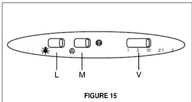
Rangehood Control Panel
The control panel is located on top of the rangehood canopy. The position and function of each control button are indicated in FIGURE 15.
text_image
L M V 1 2 31 2 1 2 FIGURE 15Rangehood Control Panel
The control panel is located on top of the rangehood canopy. The position and function of each control button are indicated in FIGURE 15.
Light On/Off Button ( L )
On/Off switch for the halogen light. Move the switch to "1" to turn the light ON and to "0" to turn it OFF.
Blower On/Off Button (M)
On/Off switch for the blower. Move the switch to "1" to turn the blower ON and to "0" to turn it OFF.
Blower Speed Button ( V )
Speed control for blower. Moving the switch to the 1 Position turns the blower on LOW. Moving the switch to the 2 Position turns the blower on MEDIUM. Moving the switch to the 3 Position turns the blower on HIGH.
For Best Results
Start the rangehood several minutes before cooking to develop proper airflow. Allow the unit to operate for several minutes after cooking is complete to clear all smoke and odors from the kitchen.
Cleaning
The stainless steel grease filters should be cleaned frequently in hot detergent solution or washed in the dishwasher. Stainless steel cleaner should be used on stainless rangehoods. Abrasives and scouring agents can scratch stainless steel finishes and should not be used to clean finished surfaces.
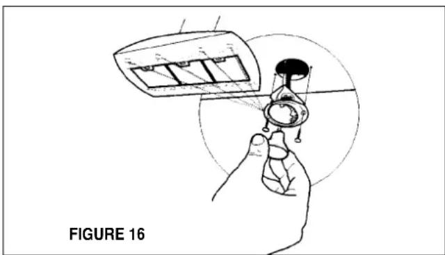
Replacing the Lamps
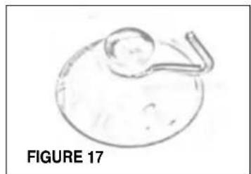
Before attempting to replace the lamps, make sure that the light switch is turned off. Remove the 2 screws (as indicated in FIGURE 16) that hold the light support and gently pull the support down from the hood. Remove the lamp from the light support and replace with new lamp. Replace the light support and fix it into place with the 2 screws.
An alternative method to replace the lamps is to use a 1 1/4" suction cup (FIGURE 17). Attach the suction cup to the bulb and pull firmly down on the bulb and replace with a new lamp.
natural_image
Illustration of a hand holding a device with a magnified inset showing internal components (no text or symbols)
natural_image
Simple line drawing of a circular object with a handle and a small circular element on top (no text or symbols)FIGURE 17
FABER WARRANTY & SERVICE (SAVE FOR YOUR RECORDS)
All Faber products are warranted against any defect in materials or workmanship for the original purchaser for a period of 1 year from the date of original purchase. This warranty covers labor and replacement parts. To obtain warranty service, contact the dealer from whom you purchased the rangehood, or the local Faber distributor. If you cannot identify a local Faber distributor, contact us at (508) 358-5353 for the name of a distributor in your area.
The Following is not covered by Faber's warranty:
- Service calls to correct the installation of your range hood, to instruct you how to use your range hood, to replace or repair house fuses or to correct house wiring or plumbing.
- Service calls to repair or replace range hood light bulbs, fuses or filters. Those consumable parts are excluded from warranty coverage.
- Repairs when your range hood is used for other than normal, single-family household use.
- Damage resulting from accident, alteration, misuse, abuse, fire, flood, acts of God, improper installation, installation not in accordance with electrical or plumbing codes, or use of products not approved by Faber.
- Replacement parts or repair labor costs for units operated outside the United States or Canada, including any non-UL or C-UL approved Faber rangehoods.
- Repairs to the hood resulting from unauthorized modifications made to the rangehood.
- Expenses for travel and transportation for product service in remote locations and pickup and delivery charges. Faber range hoods should be serviced in the home.
Record Your Information Below:
Serial #:
Date of Purchase:
OUTILS NÉCESSAIRES À L'INSTALLATION
chemical
Diagram of molecular structure with labeled components K, I, J, H, and G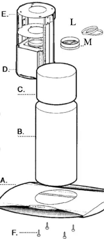
text_image
E. L M D. C. B. A. F.DÉBALLER LA HOTTE
DIMENSIONS D'INSTALLATION AVEC CONDUIT-
DIMENSIONS D'INSTALLATION SANS CONDUIT
text_image
E A D FIGURE 7text_image
L FIGURE 6text_image
C D E B A G F G FIGURE 8text_image
A F FIGURE 10CONNECTER LES CONNECTEURS INTERNE
natural_image
Technical line drawing of a mechanical assembly inside a housing, labeled as Figure 11 (no text or symbols on the diagram itself)natural_image
Diagram of a device interior with labeled components and an inset showing internal connectors (no text or symbols present)text_image
FIGURE 14natural_image
Illustration of a hand holding a small object with a magnified inset showing internal structure (no text or symbols)