Atlantic XT - Walkie-talkie MIDLAND - Free user manual and instructions
Find the device manual for free Atlantic XT MIDLAND in PDF.



| Product type | Marine VHF walkie-talkie |
| Brand | Midland |
| Model | Atlantic XT |
| Dimensions (H×W×D) | 122 × 58 × 34 mm |
| Weight | Approximately 260 g (with batteries) |
| Power supply | 6 VDC ±10% (4 AA alkaline or Ni-MH rechargeable batteries) |
| Battery type | AA alkaline batteries (1.5 V) or Ni-MH rechargeable batteries (1.2 V) |
| Frequency band | International marine VHF: TX 156.025 – 157.425 MHz |
| Number of channels | 56 international channels |
| Transmit power | 1 Watt (low) / 5 Watts (high) programmable |
| Modulation type | FM |
| Antenna impedance | 50 Ω |
| Operating temperature | -15°C to +55°C |
| Main features | Channel scan, VOX, key lock, Roger Beep, CALL button, channel 16 recall, power saving, automatic squelch, LCD backlight, high/low power selection |
| Included accessories | Belt clip, waterproof case, user manual |
| Connectors | 2.5 mm stereo jack for mic/charger, 2.5 mm mono jack for external speaker |
| Safety | Splash protection, warnings about antenna and batteries, do not open device |
| Maintenance and cleaning | Clean with a soft, slightly damp cloth (water + mild soap); do not use solvents |
| Repairability / Reset | Reset possible by removing batteries for 60 seconds; opening by unauthorized personnel voids warranty |
| Warranty | Manufacturer's warranty (except unauthorized opening) |
Frequently Asked Questions - Atlantic XT MIDLAND
User questions about Atlantic XT MIDLAND
0 question about this device. Answer the ones you know or ask your own.
Ask a new question about this device
Download the instructions for your Walkie-talkie in PDF format for free! Find your manual Atlantic XT - MIDLAND and take your electronic device back in hand. On this page are published all the documents necessary for the use of your device. Atlantic XT by MIDLAND.
USER MANUAL Atlantic XT MIDLAND
natural_image
Line drawing of a walkie-talkie device with a separate clamp and bidirectional arrow indicating movement (no text or symbols)natural_image
Line drawing of a medical device with internal components and a cross symbol (no text or labels)Figura 2
5.5 Pulsante MON (Monitor)
RX 156,300 a 162,000 MHz
Impedenza Antenna 50 Ohm
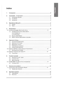
1. Introduction......2
2. Above all... safety! 3
2.1 Symbols used....3
2.2 Warnings ....3
2.3 Service....3
3. Identifying the parts....4
3.1 Display....4
3.2 Radio....5
4. Preparing the transceiver....6
4.1 Installing and removing the belt clip....6
4.2 Installing and removing batteries....6
4.2.a Installation 6
4.2.b Removal 7
4.3 Recharging batteries....7
4.4 Memory effect of rechargeable batteries ....7
5. Basic operations....8
5.1 Turning on/off....8
5.2 Selection of the operational channel....8
5.3 Volume control 8
5.4 Transmission and reception 8
5.5 Button MON (Monitor)....9
5.6 Choosing high or low transmission power 9
5.7 LCD backlight....9
5.8 Instant selection of Channel 16....9
5.9 Power saving feature....9
6. Advanced functions....10
6.1 Scanning all channels ....10
6.2 VOX Function 10
6.3 Keypad lock 10
6.4 Roger Beep (End-of-message tone): 11
6.5 CALL Function....11
7. Troubleshooting 12
7.1 Reset....12
7.2 Solution table 13
8. Technical specifications....14
8.1 Transmitter....14
8.2 Receiver 14
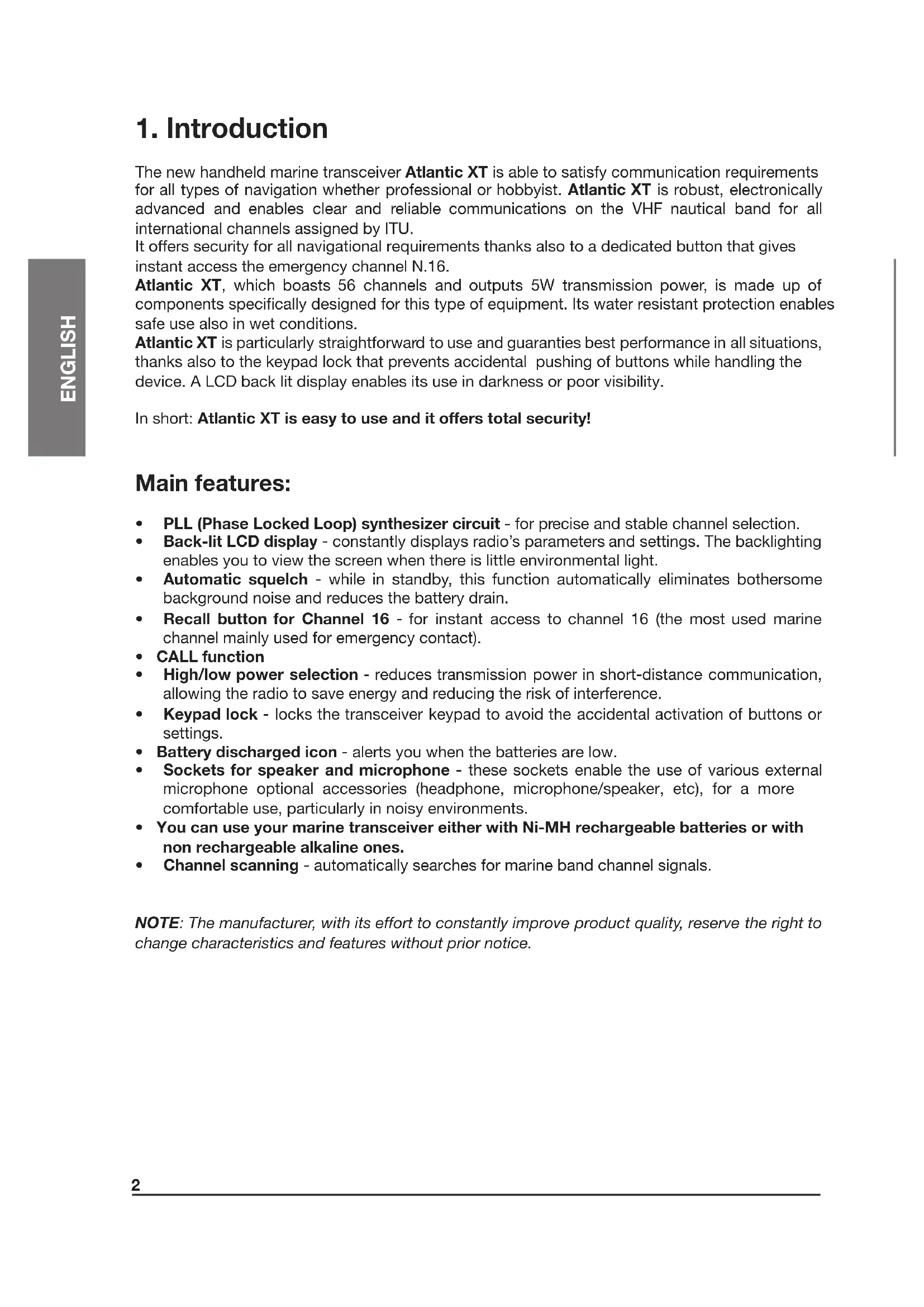
1. Introduction
The new handheld marine transceiver Atlantic XT is able to satisfy communication requirements for all types of navigation whether professional or hobbyist. Atlantic XT is robust, electronically advanced and enables clear and reliable communications on the VHF nautical band for all international channels assigned by ITU.
It offers security for all navigational requirements thanks also to a dedicated button that gives instant access the emergency channel N.16.
Atlantic XT, which boasts 56 channels and outputs 5W transmission power, is made up of components specifically designed for this type of equipment. Its water resistant protection enables safe use also in wet conditions.
Atlantic XT is particularly straightforward to use and guarantees best performance in all situations, thanks also to the keypad lock that prevents accidental pushing of buttons while handling the device. A LCD back lit display enables its use in darkness or poor visibility.
In short: Atlantic XT is easy to use and it offers total security!
Main features:
- PLL (Phase Locked Loop) synthesizer circuit - for precise and stable channel selection.
- Back-lit LCD display - constantly displays radio's parameters and settings. The backlighting enables you to view the screen when there is little environmental light.
- Automatic squelch - while in standby, this function automatically eliminates bothersome background noise and reduces the battery drain.
- Recall button for Channel 16 - for instant access to channel 16 (the most used marine channel mainly used for emergency contact).
- CALL function
- High/low power selection - reduces transmission power in short-distance communication, allowing the radio to save energy and reducing the risk of interference.
- Keypad lock - locks the transceiver keypad to avoid the accidental activation of buttons or settings.
- Battery discharged icon - alerts you when the batteries are low.
- Sockets for speaker and microphone - these sockets enable the use of various external microphone optional accessories (headphone, microphone/speaker, etc), for a more comfortable use, particularly in noisy environments.
- You can use your marine transceiver either with Ni-MH rechargeable batteries or with non rechargeable alkaline ones.
- Channel scanning - automatically searches for marine band channel signals.
NOTE: The manufacturer, with its effort to constantly improve product quality, reserve the right to change characteristics and features without prior notice.
2. Above all...safety!
2.1 Symbols used
For ease and convenience of use, this manual uses symbols to highlight urgent situations, practical advice, and general information.
! Exclamation marks such as this one indicate a crucial description regarding technical repairs, dangerous conditions, safety warnings, advice, and/or other important information. Ignoring these symbols may result in serious problems and/or damage and/or personal injury.
Notes such as this one indicate practical advice that we suggest be followed for the optimal performance of the equipment
2.2 Warnings
! DO NOT TRANSMIT WITH THE DAMAGED ANTENNA OR WITHOUT THE ANTENNA CONNECTED - although the radio is protected, this may seriously damage its R.F. power stages. Do not use your transceiver if the antenna is damaged.
! Do not keep the antenna too close to your head and body during transmission.
! Do not hold the transceiver by the antenna! This is a delicate part of the device and is vital for the proper functioning of the radio.
! Pay attention to environmental conditions - although the radio was designed to operate under the most severe conditions it is important to avoid exposure to environments that are excessively humid or dusty, or to temperatures outside the -15^ to +50^^ range. Also avoid exposure to direct sunlight.
! Avoid strong mechanical shocks and excessive vibration, the radio is designed to bear mechanical shocks and vibrations, provided that they're the normal ones borne by any electrical equipment.
! Do not use the radio, its accessories, and/or substitute the batteries in potentially explosive environments. A single spark may cause an explosion.
! BATTERIES - Strictly follow all the directions and warnings on the batteries stated at chapters 4.3 and 4.4
! Do not open the radio for any reason! The radio's precision mechanics and electronics require experience and specialized equipment; for the same reason, the radio should under no circumstances be realigned as it has already been calibrated for maximum performance. Unauthorized opening of the transceiver will void the warranty.
! Do not use detergents, alcohol, solvents, or abrasives to clean the equipment. Just use a soft, clean cloth. If the radio is very dirty, slightly dampen the cloth with a mixture of water and a neutral soap.
! Your VHF marine handheld transceiver has a built-in VHF radio transmitter. Be aware that, when you press the PTT button, the radio emits radio frequency (R.F.) energy.
! Before using the radio, ensure that all protective covers and parts are in perfect operating condition, in order to ensure maximum protection against humidity and atmospheric agents.
2.3 Service
We advise you to write the serial number of your transceiver in the space provided below. This number is found on the rear panel of the transceiver and will be useful in the event of repair/assistance and/or loss and/or theft.
Serial Number ____
3. Identifying the parts
3.1 Display
Your marine transceiver keeps you constantly updated about its operational status through a Liquid Crystal Display (LCD). The symbols and their corresponding parameters that may appear, according to the operational status of the device, are described as follows:
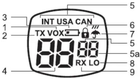
- VOX - Activation of VOX function;
- TX - During transmission (when you press PTT button) or during the sending of a 'CALL' signal;
- Battery symbol warns you of battery low charge;
- CHANNEL - These two large digits show the selected marine channel;
- INT/USA/CAN and the first of the 2 small digits - Specify the frequency band in use (USA and CAN: only for American version).
5.a Second small digit - Gives further information with regards to the channel being used (“d” duplex). - The padlock symbol appears when the keypad lock is activated.
- The rain/umbrella symbol marks activation of weather information channels (only for American version - bands USA and CAN).
- LO (Low)- appears when a low band transmission has been activated.
- RX - (busy channel): appears on the display when the transmitter is receiving a signal.
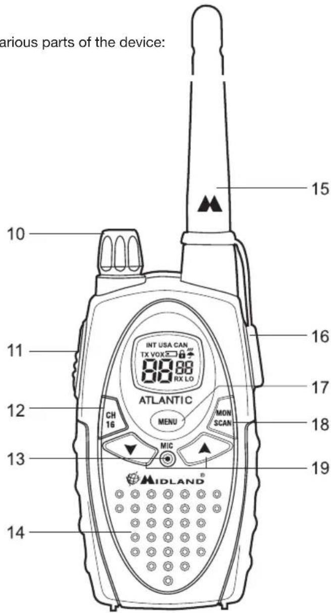
3.2 Radio
Refer to the following images to identify the various parts of the device:
-
VOLUME control - On/off switch for the device and adjusts volume of reception.
-
Button PTT (press to talk) / CALL (CALL function, see par.6.5) - Press this button to switch to transmission
-
Button 16 - Press this button to instantly recall channel 16.
-
Built-in MICROPHONE - Here is where sound is picked up by the microphone.
-
Built-in SPEAKER - Here is where the speaker is housed.
-
ANTENNA - Receives and transmits radio signals.
-
Socket MIC/CHG (under protective cover) - To connect to external audio devices (headphones, microphone etc.) and to the battery charger.
-
MENU button - Press this button to display the device's menu.
-
MONITOR/SCAN button - Press this button once to activate SCAN (scanning of channels). Keep the same button pressed for about 2 seconds to activate MON function. This function temporarily cuts off Squelch (for weak signals)
-
Scroll buttons ▲/▼- Press these buttons to select channel number and to change setting within the MENU.
4. Preparing the transceiver
Make sure the following items are supplied in the package before you start using your transceiver:
- transceiver;
- desk/wall support;
- belt clip holder;
• waterproof case with neck collar
• operational manual;
If any of the above is missing or damaged contact your supplier immediately.
4.1 Installing and removing the belt clip
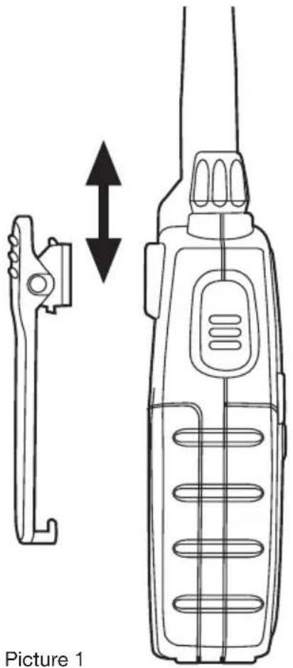
With the belt clip you can easily attach the transceiver to your belt. The clip however, must be removed in order to install or change the batteries. To remove the belt clip follow the instructions of picture 1. To fix the clip back to the device slot it in the guides at the back of the transceiver until it clicks into place.
4.2 Installing and removing batteries
The transceiver is operated by four optional AA battery. These can be either one of two types:
- Rechargeable NiMH (1,2 V) - available in different capacity (in mA/h). Batteries with higher capacity will supply longer charger but will require longer times to recharge.
• Non-rechargeable alkaline (1,5 V)
! Do not install rechargeable and alkaline batteries at the same time in your transceiver. Always use the same batteries as a set (type and make) so that you can be sure their level of charge is the same.
! If you do not use the transceiver for a long time remove the batteries.
4.2.a Installation
1) Remove the belt clip as explained in paragraph 4.1;
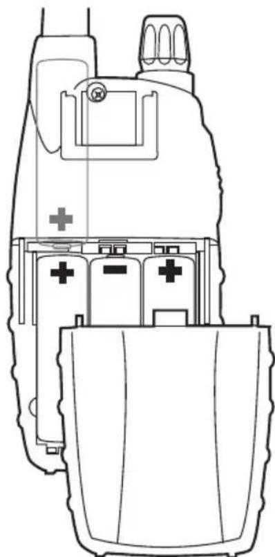
2) Open the batteries compartment as shown in picture 2;
3) Insert the batteries in the battery compartment as shown in picture 2.
4) Replace the cover on the batteries compartment.
5) Replace the belt clip.
! Be careful to insert the batteries according to their polarity as illustrated inside the compartment
! Be careful to snap close the battery cover.
natural_image
Line drawing of a walkie-talkie device with a separate clamp device shown alongside it, no text or symbols present.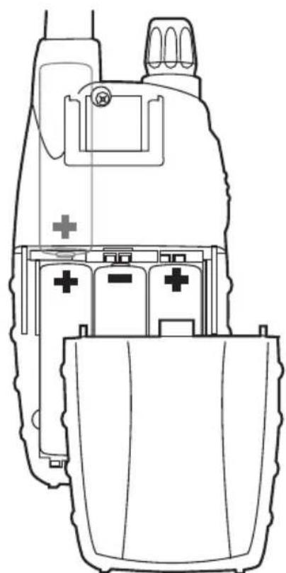
natural_image
Line drawing of a medical device with internal components and a cross symbol (no text or labels)Picture 2
4.2.b Removal
1) follow steps 1 and 2 of par 4.2.a;
2) Remove the batteries from the device;
3) Follow steps 4 and 5 of par 4.2.a.
4.3 Recharging batteries
Batteries can be recharged without taking them out of the transceiver (but the device must be turned off); Batteries take 12 -13 hours to fully recharge (rechargeable batteries1700mA/h).
To recharge batteries:
- Carefully lift the rubber protection of the socket MIC/CHG
- Insert the jack of the battery charger (sold separately) in the socket MIC/CHG of the radio, then connect the battery charger to a mains power socket. Charging will begin
- When charging is complete pull out the charger's jack from the radio and detach it from the mains. Replace the rubber protection mentioned in step 1.
! Do not overcharge the batteries! When these are fully charged the charging process does not stop automatically. Do not forget therefore, to remove the charger from the transceiver as soon as the batteries are charged.
! Do not try to charge alkaline batteries or non rechargeable batteries. Make sure that when you connect the charger only rechargeable batteries NI-MH should be contained in the batteries compartment! It is very dangerous attempting to recharge other types of batteries (for example alkaline or manganese batteries). Batteries which are not suitable to be recharged may leak, explode or even burn and cause damage!
! Using a different battery charger other than the one specified can cause damage to your device or may even cause explosions and personal injuries.
! Do not throw batteries into fire or place them near heat as this may cause explosions or personal injuries. Dispose of the batteries according to procedures set out by local regulations.
! Do not mix old and new batteries or batteries of different types or batteries which have been used in different manners. Every battery set which is being used must always be composed of the same elements.
4.4 Memory effect of rechargeable batteries
Rechargeable NiMH (Nickel-Metal-Hydrate) batteries are affected by what is known as the "memory effect". This phenomenon is associated with a drastic reduction of battery autonomy and is triggered if the batteries are regularly charged before being fully discharged and/or are not completely recharged. To avoid the memory effect:
- When possible, recharge the batteries only when they are completely discharged (until the device turns itself off during normal use)
- Do not disconnect the battery charger before the time indicated for a full battery charge.
- Discharge and recharge your batteries completely at least twice a month. In any case, the best solution for avoiding the memory effect is to use in turn two battery sets: one in use, and the other as a spare set.
The memory effect can be easily eliminated by completely discharging/charging the batteries 3 or 4 times.
The memory effect should not be confused with the normal battery life, which is 400 cycles of charge/discharge on average. It is completely normal for operating duty to decrease when the batteries have reached the end of their life; at this point, you will need to substitute the battery set.
5. Basic operations
5.1 Turning on/off
To turn on the transceiver, turn the ON/OFF/VOLUME knob clockwise until you hear it clicks: the LCD display will light up and do an Auto-Test. Subsequently you will hear 3 beeps of different tones. To turn off the transceiver, turn the knob counter-clockwise until you hear another click. The LCD display will turn off and subsequently you will hear 3 beeps of different tones.
5.2 Selection of the operational channel
1) Press once the MENU[17] button. The number of the channel will start flashing on the display.
2) Press the scroll buttons ▲/▼19] to scroll up or down the channel list till you select the desired channel.
3) Press the PTT[11] button to confirm, or wait for 5 seconds.
Refer to the table of frequencies of Chapter. 10. Moreover, the reception frequency could be different (duplex channels) from the transmission frequency or it could be the same (simplex channels). Normally communications among vessels can only take place on simplex channels.
5.3 Volume control
Turn the knob VOLUME[10] to about half way and adjust it to a comfortable level as soon as you receive a signal. If you do not receive a signal you can use the button MON/SCAN[18] described at par. 5.5.
Ensure the channel you've selected is not a reception-only channel (if it is, the transmission will be disabled) and that no one else is talking (this will appear on your display as the BUSY icon).
5.4 Transmission and reception
The button PTT[11] is located on the top left side of the device. To transmit:
1) Make sure that the selected channel is not reception-only (if it is transmission will be disabled) and that no one else is currently talking;
2) Keep button PTT[11] firmly pressed: TX[2] will appear on the display;
3) Before you start talking wait for a fraction of a second then speak normally, in the direction of the microphone, and hold the device at a distance of about 5 cm.
4) When you have finished release the button PTT[11]: TX[2] will disappear from the display;
5) When the button is in reception mode (PTT[11] not pressed) you will automatically receive any communication;
During transmission and reception try, as far as possible, to keep the antenna in vertical position and to avoid obstacles towards the direction of the other party.
5.5 Button MON (Monitor)
The Monitor button is for temporarily excluding (opening) the squelch, in order to listen to signals that are too weak to keep the squelch permanently opened. By excluding the squelch you will avoid listening the communication “chopped” by the squelch. In order to activate the Monitor function, so as to listen to all traffic on the selected channel, keep pressed the MON/SCAN[18] button for about 2 seconds. Keep pressed the button MON/SCAN[18] for about 2 seconds to disable this function.
5.6 Choosing high or low transmission power
Batteries are drained more quickly during transmission. In order to extend the battery life you can select the low power when transmitting over short distances:
1) Press the MENU[17] button twice and the writing Pr will display.
2) Select LO[8] using the scroll buttons ▲[19].
3) Press PTT[11] to confirm, or wait for 5 seconds.
If you want to transmit a longer distance repeat the above procedure to select the high power. At step 2 use the scroll buttons ▲/▼[19] to make the writing LO[8] disappear. When the batteries are in good conditions, high power is about 5 watt, whereas low power is about 1 watt.
A low battery level during transmission will have a negative effect on the performance of your device.
5.7 LCD backlight
If there is insufficient light to read the display you can press the MENU[17] button to switch the display back light on for about 5 seconds.
Switching the back light on the display adds an additional drain on the batteries. Try to make a moderate use of this.
5.8 Instant selection of Channel 16
Channel 16 is the marine channel most frequently used for emergency. Your transceiver is equipped with a button that provides instant access to this channel. To recall rapidly channel 16 press the button CH 16[12]. No matter what mode the device is operating, channel 16 will be selected immediately. To go back to the previously selected channel press again the button CH 16[12].
5.9 Power saving feature
The battery power saving feature enables a reduction in the consumption of up to 50%; Power saving comes on automatically when the transceiver does not receive any signal for more than seven seconds. When the battery pack is discharged (the icon ☐[3] appears on the display) batteries need to be substituted or recharged if they are Ni-MH type.
6. Advanced functions
6.1 Scanning all channels
Atlantic XT can automatically search for signals throughout the marine band by scanning, i.e. selecting the channels in rapid sequence. When a signal is detected, the scanning pauses on that channel and remains blocked for five seconds before automatically begins scanning again to give you the chance to find other communication.
Press briefly the button MON/SCAN[18] to start scanning:
Press again MON/SCAN[18] to stop scanning. Your transceiver will go back to the channel from which the scanning originally started.
Once you are tuned in the communication you were looking for, press PTT[11] to talk on the selected channel. Atlantic XT will however remain in scanning mode (which is indicated by the flashing of the channel on the display) and it is possible to start scanning again by pressing on the scroll buttons ▲/▼[19]. If you press PTT[11] during scanning you can transmit on the channel from which the scanning started. The scroll buttons ▲/▼[19] allow you to change the direction of scanning (from lower channels to higher ones or vice versa) and therefore to skip communications which are of no interest.
6.2 VOX Function
Atlantic XT enables hands free conversations through VOX function. The degree of sensitivity of VOX function can be adjusted to three different levels. You can enable VOX function with or without accessories.
1) To activate VOX function press the MENU[17] button three times and VOX[1] will appear on the display
2) Use the scroll ▲/▼19] buttons to select:
- OFF: Disabled;
• 1: 1° Level (low sensitivity);
• 2: 2^ Level (high sensitivity);
3) Press PTT[11] to confirm or wait for 5 seconds
To disable VOX function follow the instructions above and select option oF.
VOX has a better performance when used in conjunction with the optional accessories which plug in the appropriate outlet. This will enable you to keep the microphone at constant distance from your mouth and by holding the transceiver on the belt you can carry on working with your hands in total freedom.
6.3 Keypad lock
You can lock the keypad of your transceiver and avoid pressing buttons accidentally. All buttons are disabled with the exception of MON[18] (opening squelch), PTT[11], 16[12], MENU[17] (removal of keypad lock).
To insert keypad lock:
1) Press four times the MENU[17] button; the symbol 🔊[6] will appear on the display
2) Using the scroll buttons ▲[19] select on
3) Press PTT[11] to confirm or wait for 5 seconds.
To remove keypad lock repeat the above procedure. At step 2 use the scroll button to select oF.
6.4 Roger Beep (End-of-message tone):
When you release the PTT[11], that is every time you end transmission, Atlantic XT gives out a sound that indicate to the other party that s/he can start talking. This function is factory set. To disable the function:
1) Press five times the MENU[17] button; the symbol rb will appear on the display
2) Using the scroll buttons ▲[19] select oF
3) Press PTT[11] button to confirm or wait for 5 seconds.
To reactivate this function repeat the above procedure. AI step 2 use the scroll buttons ▲/▼19] to select on.
6.5 CALL Function
The CALL function warns other users tuned in on the same channel of the arrival of a call. To send the signal to another user press twice button PTT[11]. On the display TX[2] will appear and the Speaker [14] will give out a sequence of sounds which you have previously chosen.
Atlantic XT gives you the chance to select different tones to send. Tone 1 is factory set.
To select the sequence of tones:
1) Press six times the MENU[17] button; the writing CA will appear on the display
2) Using the scroll buttons ▲/▼[19] select 1, 2 o 3. During selection you will be able to hear the relative tone.
3) Press PTT[11] button to confirm, or wait for 5 seconds.
7. Troubleshooting
Your Atlantic XT is designed to provide you with years of optimal performance. If for some reason problems arise, refer to this chapter before contacting a service centre in your region.
7.1 Reset
If your transceiver experiences a logical malfunction (improper symbols on the display, blocking of functions, etc.), it may not be experiencing a true failure, but rather a problem caused by external factors. For example, it may have an incorrect setting brought on by a noise or spikes in the electrical system during battery recharging. In such cases, you can reset the transceiver to its factory-programmed settings, by resetting all parameters:
1) Turn off the transceiver
2) Remove the batteries for about 60 seconds (Par.4.2)
Before you go ahead with the reset, we recommend that you take note of all the setting you have carried out as they will be deleted.
7.2 Solution table
| Problem Possible Cause Solution Ref. | |||
| The radio does not turn on | The batteries are not charged and/or are not correctly inserted | Ensure the batteries are charged and correctly inserted in the radio | 4.24.3 |
| The radio turns on, but does not receive signals | The volume is too low The volume is too low 5.3 | ||
| You are unsuccessful in establishing contact with your party | Incorrect selection of marine channel or local band | Check your channel and band | 5.2 |
| Reception is broken and/or with noise | Signal is extremely weak Temporarily deactivatesquelch using the Monitor function | 5.5 | |
| Your party is too far away and/or transceiver antenna is shielded by obstacles in the direction of your party | Move closer to your party and/or move the transceiver to a less shielded area | - | |
| Other users are using the same radio channel | Check the radio traffic on the selected channel and change channels if necessary | 5.2 | |
| The radio is positioned too close to other interference devices (televisions, computers, transmitters, etc.) | Move the radio away from the interference devices | - | |
| Battery life is short Excessive use of display backlighting | Use less display backlighting | 5.7 | |
| Excessive use of transmission | Try to reduce transmission times and/or use low transmission power | ||
| Memory effect is occurring with the batteries | Eliminate memory effect 4.4 | ||
| Logical malfunction (improper symbols on the display, blocking of functions, etc.) | Incorrect setting brought on by electrical disturbance | Reset your radio 7.1 | |
8. Technical specifications
Channel bands ....56 International
Frequency generation.... PLL synthesizer
Frequency range (International band).... TX 156,025 - 157,425 MHz
...... RX 156,300 - 162,000 MHz
Antenna Impedance ....50 Ohm
Power Supply. 6 VDC +/- 10%
Operating Temperature Range. from -15° to +55°C
Size 122x58x34 mm (HxWxD)
Weight (without batteries).... 119 grams
Duty cycle (% on 1 hour) TX 5%, RX 5%, Stand-by 90%
8.1 Transmitter
Output power 1 or 5 Watt (Selectable)
Modulation type ...... FM
Residual noise attenuation 40dB
Audio distortion....3%
8.2 Receiver
Sensitivity @ 12dB SINAD.... 0,3μV
Squelch sensitivity....12dBV
Adjacent channel rejection.... 60dB
Audio Output Power 300mW @ 10% THD
Intermediate frequencies.... 1°:21,4 MHz ; 2°:450 KHz
Spurious rejection 60dB
Residual noise attenuation....43dB
Socket for external microphone and charger 2.5 mm stereo jack
Socket for external speaker 2,5mm mono jack
Specifications are subject to modification without forewarning.
Inhaltsverzeichnis
1. Einführung 2
natural_image
Line drawing of a medical device casing with internal components and a plus symbol (no text or labels)Zeichnung 2
natural_image
Line drawing of a walkie-talkie device with a separate clamp and bidirectional arrow indicating movement (no text or symbols)Figura 1
natural_image
Technical line drawing of a vehicle battery pack with no visible text or symbolsFigura 2
RX 156,300 a 162,000 MHz
Impedancia Antena 50 Ohm
1. Introduction......2
2. Avant tout... la securite!....3
2.1 Symboles utilisés ....3
2.2 Avertissements....3
2.3 Service....3
8. Specifications techniques....15
natural_image
Technical line drawing of a mechanical device with battery and switch components (no text or symbols)Schéma 2
8. Specifications techniques
RX 156,300 - 162,000 MHz
Poids (sans batteries) 119 grammes
Distorsion audio ....3%
8.2 Récepteur
Réjection canal adjacent 60dB
natural_image
Line drawing of a walkie-talkie device with a separate clamp and bidirectional arrow indicating movement (no text or symbols)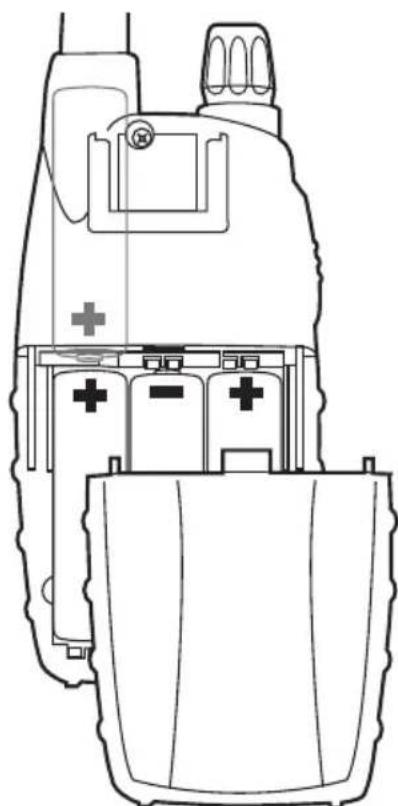
natural_image
Line drawing of a medical device with internal components and a cross symbol (no text or labels)Figura 2
5.5 Botão MON (Monitor)
RX 156,300 a 162,000 MHz
INTERNATIONAL CHANNEL (INT)
| Channel ID | Ship Station | |
| Tx Frequency | Rx Frequency | |
| 01 156, | 050 MHz 160,650 | MHz |
| 02 156, | 100 MHz 160,700 | MHz |
| 03 156, | 150 MHz 160,750 | MHz |
| 04 156, | 200 MHz 160,800 | MHz |
| 05 156, | 250 MHz 160,850 | MHz |
| 06 156, | 300 MHz 156,300 | MHz |
| 07 156, | 350 MHz 160,950 | MHz |
| 08 156, | 400 MHz 156,400 | MHz |
| 09 156, | 450 MHz 156,450 | MHz |
| 10 156, | 500 MHz 156,500 | MHz |
| 11 156, | 550 MHz 156,550 | MHz |
| 12 156, | 600 MHz 156,600 | MHz |
| 13 156, | 650 MHz 156,650 | MHz |
| 14 156, | 700 MHz 156,700 | MHz |
| 15 156, | 750 MHz 156,750 | MHz |
| 16 156, | 800 MHz 156,800 | MHz |
| 17 156, | 850 MHz 156,850 | MHz |
| 18 156, | 900 MHz 161,500 | MHz |
| 19 156, | 950 MHz 161,550 | MHz |
| 20 157, | 000 MHz 161,600 | MHz |
| 21 157, | 050 MHz 161,650 | MHz |
| 22 157, | 100 MHz 161,700 | MHz |
| 23 157, | 150 MHz 161,750 | MHz |
| 24 157, | 200 MHz 161,800 | MHz |
| 25 157, | 250 MHz 161,850 | MHz |
| 26 157, | 300 MHz 161,900 | MHz |
| 27 157, | 350 MHz 161,950 | MHz |
| 28 157, | 400 MHz 162,000 | MHz |
| Channel ID | Ship Station | |
| Tx Frequency | Rx Frequency | |
| 60 156, | 025 MHz 160,625 | MHz |
| 61 156, | 075 MHz 160,675 | MHz |
| 62 156, | 125 MHz 160,725 | MHz |
| 63 156, | 175 MHz 160,775 | MHz |
| 64 156, | 225 MHz 160,825 | MHz |
| 65 156, | 275 MHz 160,875 | MHz |
| 66 156, | 325 MHz 160,925 | MHz |
| 67 156, | 375 MHz 156,375 | MHz |
| 68 156, | 425 MHz 156,425 | MHz |
| 69 156, | 475 MHz 156,475 | MHz |
| 71 156, | 575 MHz 156,575 | MHz |
| 72 156, | 625 MHz 156,625 | MHz |
| 73 156, | 675 MHz 156,675 | MHz |
| 74 156, | 725 MHz 156,725 | MHz |
| 75 156, | 775 MHz 156,775 | MHz |
| 76 156, | 825 MHz 156,825 | MHz |
| 77 156, | 875 MHz 156,875 | MHz |
| 78 156, | 925 MHz 161,525 | MHz |
| 79 156, | 975 MHz 161,575 | MHz |
| 80 157, | 025 MHz 161,625 | MHz |
| 81 157, | 075 MHz 161,675 | MHz |
| 82 157, | 125 MHz 161,725 | MHz |
| 83 157, | 175 MHz 161,775 | MHz |
| 84 157, | 225 MHz 161,825 | MHz |
| 85 157, | 275 MHz 161,875 | MHz |
| 86 157, | 325 MHz 161,925 | MHz |
| 87 157, | 375 MHz 157,375 | MHz |
| 88 157, | 425 MHz 157,425 | MHz |

- Pulsante MON (Monitor)
- Introduction......2
- Above all... safety! 3
- Identifying the parts....4
- Preparing the transceiver....6
- Memory effect of rechargeable batteries ....7
- Basic operations....8
- Advanced functions....10
- Roger Beep (End-of-message tone): 11
- Troubleshooting 12
- Technical specifications....14
- Introduction
- Main features:
- Above all...safety!
- Symbols used
- Warnings
- Service
- Identifying the parts
- Display
- Radio
- Preparing the transceiver
- Installing and removing the belt clip
- Installing and removing batteries
- 4.2.a Installation
- 4.2.b Removal
- Recharging batteries
- Memory effect of rechargeable batteries
- Basic operations
- Turning on/off
- Selection of the operational channel
- Volume control
- Transmission and reception
- Button MON (Monitor)
- Choosing high or low transmission power
- LCD backlight
- Instant selection of Channel 16
- Power saving feature
- Advanced functions
- Scanning all channels
- VOX Function
- Keypad lock
- Roger Beep (End-of-message tone):
- CALL Function
- Troubleshooting
- Reset
- Solution table
- Technical specifications
- Transmitter
- Receiver
- Inhaltsverzeichnis
- Einführung 2
- Avant tout... la securite!....3
- Specifications techniques....15
- Specifications techniques
- Récepteur
- Botão MON (Monitor)
Brand : MIDLAND
Model : Atlantic XT
Category : Walkie-talkie