
Purity 600 Steam - Water filter BRITA - Free user manual and instructions
Find the device manual for free Purity 600 Steam BRITA in PDF.
| Product Type | Water filtration system for steam and traditional ovens |
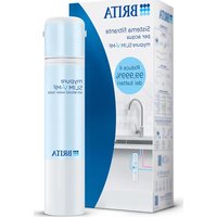
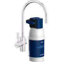
| Brand and Model | BRITA Purity 600 Steam |
| Dimensions (L x D x H) | 249 mm x 222 mm x 520 mm |
| Weight (dry/wet) | 12 kg / 15 kg |
| Operating pressure | 2 bar to 6.9 bar |
| Water temperature | 4 °C to 30 °C |
| Nominal flow rate | 120 l/h |
| Max. flow rate at 1 bar pressure loss | 500 l/h |
| Comparative capacity (DIN 18879-1) | 4 734 litres |
| Power supply (display option) | Integrated battery, service life ~10 years |
| Main functions | Decarbonation, reduction of limescale, heavy metals (lead, copper), chlorine and organic impurities |
| By-pass setting | 4 positions (0 to 3) according to local hardness |
| Electronic display option | Indicates remaining capacity, by-pass setting, replacement date |
| Maintenance and cleaning | Clean the exterior with a damp cloth; do not use aggressive cleaning products |
| Cartridge replacement | Every 6 to 12 months (max 12 months) or depending on saturation |
| System service life | 10 years maximum (pressure chamber and cover) |
| Hose replacement | Every 5 years |
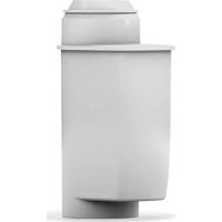
| Spare parts and references | Filter cartridge PURITY 600 Steam: ref. 1000252; Complete system (without display): ref. 1000245 |
| Warranty | 2 years (subject to compliance with instructions) |
| Storage/transport temperature | -20 °C to 50 °C |
| Safety instructions | Use only on cold drinking water; do not expose to detergents; installation by qualified personnel |
Frequently Asked Questions - Purity 600 Steam BRITA
User questions about Purity 600 Steam BRITA
0 question about this device. Answer the ones you know or ask your own.
Ask a new question about this device
Download the instructions for your Water filter in PDF format for free! Find your manual Purity 600 Steam - BRITA and take your electronic device back in hand. On this page are published all the documents necessary for the use of your device. Purity 600 Steam by BRITA.
USER MANUAL Purity 600 Steam BRITA
natural_image
Three technical line drawings of mechanical components or structural supports, shown from different angles (no text or symbols present)| Handbuch | deutsch |
| Manual | english |
| Mode d'emploi | français |
| Handboek | nederlands |
| Manuale | italiano |
| Manual | español |
| Podręcznik | polski |
| Manual | dansk |
| Руководство по эксплуатации | русский язык |
Deutsch Seite 2–19
1 Definition of Terms
2 General Information
3 Operating and Safety Instructions
4 Installation
5 Commissioning a New Filter
6 Replacing the Filter Cartridge
7 Filter Capacity
8 Repair
9 Query Mode
10 Troubleshooting
11 Battery
12 Technical Data
13 Order Numbers
Français Page 37–53
1 Begriffsübersicht
natural_image
Diagram showing a mechanical device rotating around a cylindrical component with directional arrows indicating motion (no text or symbols)STD 4 = PURITY 450 Quell ST
STD 6 = PURITY 600 Quell ST
STD 12 = PURITY 1200 Quell ST
STM 4 = PURITY 450 Steam
STM 6 = PURITY 600 Steam
STM 12 = PURITY 1200 Steam
FIN 6 = PURITY Finest 600
FIN 12 = PURITY Finest 1200

4 sec

2 sec

< 1 sec

2 sec
< 1 sec

< 1 sec

2 sec
natural_image
Diagram of a mechanical device with a cup and lever mechanism (no text or symbols)- Filtersystem horizontal hinlegen.
natural_image
Diagram of a mechanical device with rotating components and directional arrows indicating motion (no text or symbols)Filtersystem PURITY 450 Steam/PURITY 600 Steam/PURITY 1200 Steam
1 Definition of Terms
① Pressure Vessel
② Filter Cartridge
③ Pressure Vessel Lid
⑤ Display Unit (optional)
⑥ Inlet Hose
⑦ Connection Inlet Hose
⑧ Terminal Device Connection
⑨ Flush Valve with Water Outlet
⑩ Connection of Outlet Hose
⑪ Filter Change Sticker
⑫ Kick Loops
13 Ejector Base
⑭ Display of the Display Unit (optional)
15 Lock
16 Mantle Handle
⑰ Reducer 1"-3/4"
18 Transport Protective Cap
19 Bypass Screw
20 Lid Handle
21 Flush Hose
④ Connector Head (optionally with measuring unit)
2 General Information
2.1 Function and Application
The BRITA PURITY Steam water filter system optimises tap water specially for combi ovens and conventional ovens. It decarbonates drinking water, thereby reducing scale deposits in and on the terminal equipment. Depending on the bypass setting, calcium and magnesium ions as well as heavy metal ions such as lead and copper are selectively removed from the drinking water. In addition, the filter material not only reduces cloudiness and organic impurities but also substances that impair smell and taste, such as chlorine residues.
The bypass setting, which is specially designed for combi ovens and conventional ovens, matches the reduction in the carbonate hardness to the local water hardness in order to achieve an optimum filtrate quality. The increased flow and the reduced pressure loss enable the smooth operation of the combi oven.
The filter systems are available in three different filter system sizes (PURITY 450 Steam, PURITY 600 Steam and PURITY 1200 Steam), each in a version without integrated measuring and display electronics or with measuring and display electronics (Advanced Control System, ACS Technology). Filter systems with ACS Technology show you the current remaining capacity and bypass setting of your filter cartridge, the set type and size of the filter system and the last replacement date of the filter cartridge. This ensures optimum filter control and water filtrate quality. Further information on the filter system with ACS Technology can be found in Chapter 5.2.
2.2 Guarantee Provisions
The PURITY Steam filter systems are subject to the statutory warranty of two years. A guarantee claim may be asserted only if all instructions in this manual are followed and observed.
2.3 Storage/Transport
Adhere to the ambient conditions in the Technical Data (Chapter 12) for storage and transport.
The manual should be seen as part of the product and kept for the whole service life of the filter system and passed on to subsequent owners.
2.4 Recycling/Disposal
Disposing of this product and its packaging in the correct manner protects people and the environment.
The battery and display unit must not be burnt and must not be disposed of in domestic waste. Please ensure that these are disposed of correctly, in accordance with local regulations. See also Chapter 11.
Used filter cartridges can be returned to the BRITA addresses listed (see back of the cover).
3 Operating and Safety Instructions
3.1 Qualified Personnel
Installation and maintenance of the filter system may be carried out only by trained and authorised personnel.
3.2 Correct Use
The product can only operate perfectly and safely if it is installed, used and serviced in the manner described in this manual.
Note: the filter system and system-specific PURITY Steam filter cartridges may only be used upstream from end devices such as hot air steamers, combi ovens and conventional ovens.
3.3 Liability Exclusion
Installation must be performed precisely in accordance with the instructions in this manual. BRITA shall not be held liable for any damage, including subsequent damage, arising from the incorrect installation or use of the product.
3.4 Specific Safety Information
- Only water of drinking water quality may be used as intake water for the BRITA water filter system. The BRITA water filter system is only suitable for cold water use within the water intake temperature stated in Chapter 12. No microbiologically impaired water or water of unknown quality may be used without prior appropriate disinfection.
- If there are official instructions to boil tap water, the filter system must be decommissioned. When the requirement to boil water comes to an end, the filter cartridge must be replaced and the connections cleaned.
- For hygiene reasons, the filter material of the cartridge is subjected to a special treatment with silver. A small quantity of silver, which is harmless to health, may be released into the water. This is in compliance with the World Health Organisation (WHO) recommendations for drinking water.
- Note for people with kidney disease or dialysis patients: During the filter process the potassium content may be increased slightly. If you suffer from kidney disease and/or have to stick to a special potassium diet, we recommend prior agreement with your doctor.
- The water filtrate is classified in Category 2 according to DIN EN 1717.
- BRITA recommends that the filter system not be decommissioned for a long period. If the BRITA PURITY Steam filter system is not used for several days (two to three days), we recommend that the filter system be flushed with at least X litres according to the table below. After stagnation periods of over four weeks, the filter should be flushed with at least Y litres or else replaced. Please also note that the maximum usage period of the filter cartridge is twelve months (Chapter 6).
| Filter system Flush quantity X | after 2–3 days stagnation | Flush quantity Y after 4 weeks stagnation |
| PURITY 450 Steam 6 litres 30 litres | ||
| PURITY 600 Steam 12 litres 60 litres | ||
| PURITY 1200 Steam 24 litres 120 litres |
- The filter system is not resistant to heavily concentrated cleaning agents (e.g. bleach, chlorinated solvents, heavy oxidants) and must not come into contact with them.
- The filter system must not be opened or dismantled during operation. The filter cartridge must not be opened.
- The pressure vessel and the pressure vessel lid of the filter systems have a service life of up to ten years (from the date of installation), provided that they are installed and used correctly and the operating conditions outlined in the Technical Data chapter are adhered to. They must always be replaced after a maximum of ten years. The hoses must be replaced in rotation after a maximum of five years.
• Production date:
| Production code sticker filter cartridge and box, example: B612002010 | |
| 6 Production year, here: 2016 | |
| 12 Production week, here: calendar week 12 | |
| 002 Batch | No. of filter medium, here the second batch filled in terms of quantity |
| 010 Serial | number of the filter cartridge, here the tenth cartridge from the second batch |
| Production code sticker connector head - Example: 1001801 E 619316008764 | |
| 1001801 | BRITA identification number |
| E Supplier | ID |
| 6 Production year, here: 2016 | |
| 19 Production week, here: calendar week 19 | |
| 3 Production day from Monday (1) to Friday (5), here: Wednesday | |
| 16 Production year, here: 2016 | |
| 008764 Serial identification number | |
| Production date of pressure vessel and pressure vessel lid, example: 0315 | |
| 03 Production month, here: March | |
| 15 Production year, here: 2015 |
3.5 Safety Assembly Instructions
- The terminal device operated with the filter must be free of limescale prior to installation.
- Protect the filter system from sunlight and mechanical damage. Do not assemble near sources of heat and open flames.
- A stop valve must be installed before the filter system intake hose.
- If the water pressure is higher than 6.9 bar or if there are statutory requirements, a pressure reducer must be installed before the filter system.
- A non-return valve tested by the DVGW has been factory-installed at the water intake of the filter head.
- No copper pipes and no galvanised or nickel-plated pipes/connectors may be installed between the water filter and the consumer. The use of BRITA hose sets is recommended here. When choosing the material for parts that come into contact with water after the BRITA filter system it must be remembered that, due to the process, decarbonised water contains free carbon dioxide.
- All parts must be installed in accordance with the country-specific guidelines on the installation of drinking water facilities.
- For erection and operation of the filter system, the BG rules "Working in Kitchens" of the Specialist Committee "Foods" of the BGZ (BGR111) must be observed.
4 Installation
Caution: Prior to installation, read the Technical Data (Chapter 12) and the Operating and Safety Information (Chapter 3). After the product has been stored and transported at temperatures below 0°C, it must be stored with the original packaging open for at least 24 hours at ambient temperature (Chapter 12) before commissioning.
4.1 Delivery Scope
Prior to installation, remove the entire delivery scope from the packaging and check that everything is present:
1 x Pressure Vessel ①
1 x Pressure Vessel Lid ③
1 x Filter Cartridge ②
1 x Manual
1 x Carbonate Hardness Test
1 x Sticker for Service Pass (orange)
1 x Adapter 1"-3/4"
If parts of the delivery scope are missing, please contact your local BRITA office (see the back of the cover).
4.2 Assembling the Pressure Vessel and the Pressure Vessel Lid
- Stand with both feet on the kick loops ⑫.
- Lift the pressure vessel ① and turn it clockwise until the mantle handles ⑯ are over the kick loops ⑫.
- Remove the transport protective cap ⑱ from the filter cartridge.
- Check that the O-ring seal of the filter cartridge ② is correctly seated in the groove and also check for dirt and damage.
Note: lubricant at the factory.
natural_image
Diagram of a mechanical device with rotating components and directional arrows indicating motion (no text or symbols)- Stand on the kick loops ⑫ with both feet and place the pressure vessel lid ③ on the pressure vessel ①. The position of the arrow marking on the lid handle ⑳ must match the "INSERT" groove.
- Press the pressure vessel lid ③ down and turn clockwise until the lock ⑮ engages.
4.3 Assembly of Inlet and Outlet Hoses
Note: The inlet and outlet hoses are not included in the standard scope of delivery. The use of BRITA hose sets is recommended (Chapter 13).
- Fit inlet hose ⑥ at the inlet of the connector head ④ and outlet hose ⑩ at the outlet of the connector head ④.
Note: Inlet "IN" and outlet "OUT" of the connector head ④ are equipped with O-rings as seals, therefore no additional flat seals may be used here. Check that the O-rings are seated correctly.
Caution: The max. tightening torque at the 1" and 3/4" connections must not exceed 15 Nm! Only hose connections with flat seals may be used. Hoses with conical screwed connections damage the filter head connections and invalidate any guarantee claims. Only hoses that comply with DVGW-W 543 may be used to connect the device.
Before assembly, note the direction of flow on the upper side of the filter head, "IN" = water inlet, "OUT" = water outlet. Prior to installation, note installation dimensions and operating position (Chapter 12). If no original hoses are used, the 1"-3/4" ⑰ adapter supplied must be used to ensure the return valve is sealed correctly (pre-fitted in the water inlet).
5 Commissioning a New Filter
5.1 Bypass Setting for Filter Systems without and with Measuring and Display Unit
- Identify the local carbonate hardness in German hardness °dH (BRITA nomenclature °KH) using the enclosed carbonate hardness test.
- Check the bypass setting on the bypass screw 19.
Note: The bypass has been set to Position 1 in the factory, and must be changed to suit the local carbonate hardness and the application (Chapter 7).
5.2 Commissioning the Filter Systems with Measuring and Display Unit
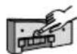
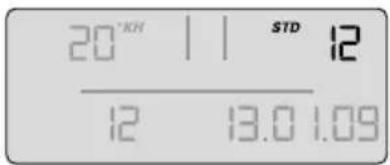
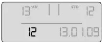
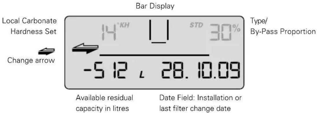
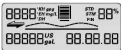
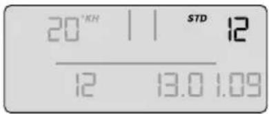
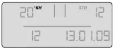
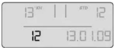
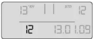
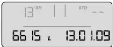
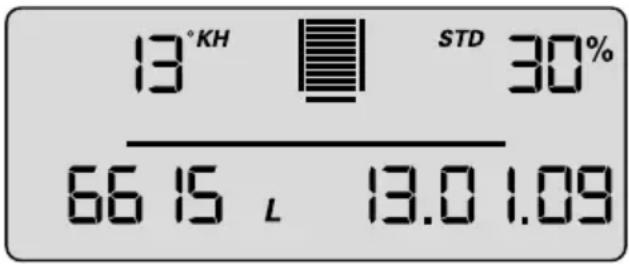
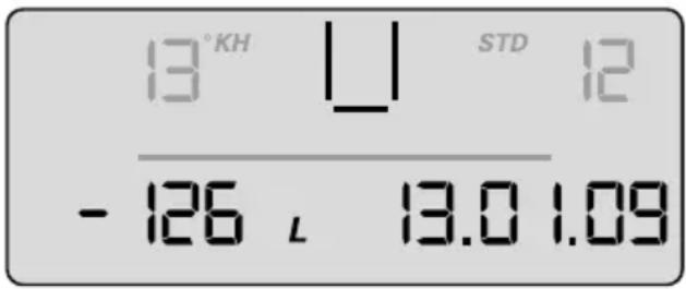
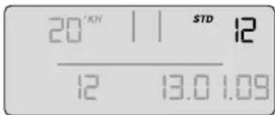
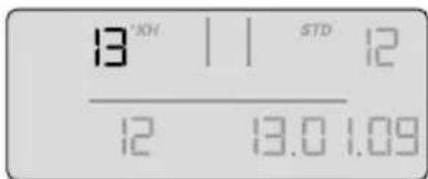
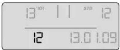
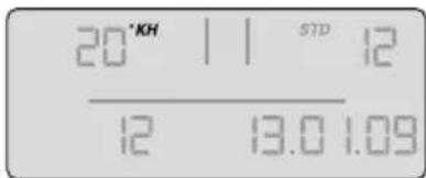
Representation in operating mode
Bar Display
Local Carbonate Hardness Set
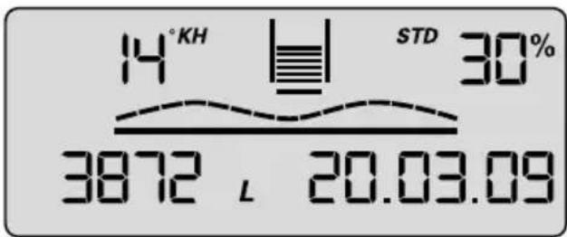
Available residual capacity in litres
Date Field: Installation or last filter change date
Type/
By-Pass Proportion
Flow Symbol
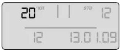
Carbonate Hardness
The units of carbonate hardness can be set as required to German °dH (= display setting °KH), English (°e = Clark) (= display setting °EH), French (°f) (= display setting °FH), American (grains per gallon) (= display setting gpg) or international hardness values (mg/l CaCO _3 ) (= display setting mg/L).
If the setting for the type of hardness (= unit) is changed while the filter is operating, the values that were set originally are converted automatically.
Bar chart
Representation of the remaining capacity using bar charts. After installation of a new filter system or after a filter change, the symbolised filter cartridge is completely filled with 10 bars.
Bypass proportion in percentage
The by-pass proportion is defined as the proportion of decarbonised water in the total amount of filtrate and is indicated as a percentage.
Flow symbol
When water is removed via the filter system, a graphic wave is shown on the display.
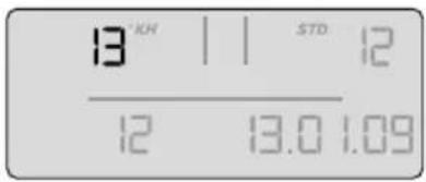
Available remaining capacity of the filter cartridge
The remaining capacity of the filter cartridge is shown in litres or in US gallons, depending on which has been selected.
When water is removed, it counts backwards in 1 litre or 1 US gallon stages. If the cartridge is already exhausted, the capacity is indicated as being negative by flashing.
With a remaining capacity of 20% the last two bars in the bar chart start to flash.
With a remaining capacity of 10% the last bar in the bar chart flashes with the two change arrows.
From a remaining capacity of 0% the negative bars and the change arrows flash alternately with the remaining capacity shown in negative.
If the monthly limit has been reached up to a month before expiry of the set time limit, it is signalled by the date field flashing.
If the monthly limit is 100% reached, it is signalled by alternate flashing of the date field and the change arrows.
If the remaining capacity and the monthly limit are exceeded, the negative remaining capacity and the date field flash alternately with the change arrows.
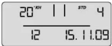
Date of the filter commissioning or last filter cartridge change
The date of filter commissioning or last filter cartridge change is indicated as follows:
| Example: 28/10/09 | |
| 28 Day, here the 28th day | |
| 10 Month, here October | |
| 09 Year, here 2009 | |
Selecting the units of measurement
You can choose between European, American and international units of measurement on the display.
For European units of measurement: depending on the type of filter system (STD, STM or FIN), select the specified unit of measurement for water hardness °KH, °EH, °FH or °DH. The unit of volume and date format are then automatically displayed in litres and DD/MM/YY respectively. For American units of measurement, select gpg (unit of measurement for water hardness); the unit of volume and the date format are then automatically displayed in US gallons and MM/DD/YY respectively.
For international units of measurement, select mg/L (unit of measurement for water hardness); the unit of volume and the date format are then automatically displayed in litres and DD/MM/YY respectively.
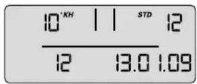
Parameterisation
The following parameters have to be entered:
- Filter system type and size
STD 4 = PURITY 450 Quell ST
STD 6 = PURITY 600 Quell ST
STD 12 = PURITY 1200 Quell ST
STM 4 = PURITY 450 Steam
STM 6 = PURITY 600 Steam
STM 12 = PURITY 1200 Steam
FIN 6 = PURITY Finest 600
FIN 12 = PURITY Finest 1200
• Water hardness unit and water hardness value
The following units of hardness may be selected for the various types of filter system:
Unit of carbonate hardness for filter system types STD and STM:
°KH (German unit of hardness)
°EH (English unit of hardness)
°FH (French unit of hardness)
gpg (American unit of hardness)
mg/L (international unit of hardness)
Unit of total hardness for filter system type GYP may be
°DH (German unit of hardness)
°EH (English unit of hardness)
°FH (French unit of hardness)
gpg (American unit of hardness)
mg/L (international unit of hardness)
• Monthly limit 2–12
Carbonate Hardness Type/Filter System Size
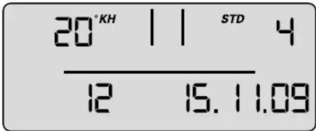
Date fieldExhaustion after months
- Reminder function filter usage period in months
Irrespective of the remaining capacity display function, you can set a monthly limit of 2–12 months to activate a reminder function for filter replacement. If the monthly limit has been reached up to a month before the export of the set time limit, it is signalled by the date field flashing. Factory set to 12 months.
Example: When set to 9 months, the date field starts to flash on the display after 8 months.
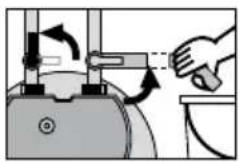
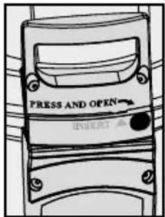
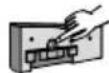
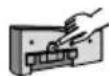
Operating the display unit
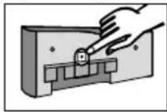
To operate the display unit, it must be removed from the connecting fittings. Slide the display housing up approx. 10 mm and pull off the display unit.
The display unit is operated using a button on the back of the display unit. The display unit is supplied in standby mode. To activate the display, press the button on the back once briefly and then reset after inputting the parameters.
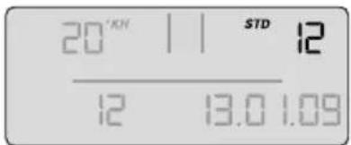
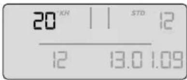
Parameter input water hardness and filter system size
At this level, parameters needed for operation are set manually.
The type and size of filter system is selected, the unit of hardness is set, the local carbonate hardness or total hardness of the tap water is entered, and the maximum cartridge service life (monthly limit) is activated. After this the parameters must be accepted.
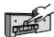
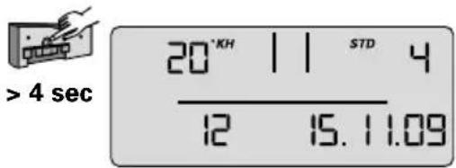
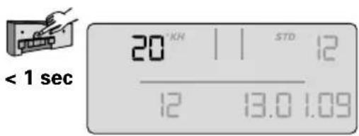
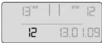
- To activate the display, press the back button once (< 1 second) until the data field appears.
< 1 sec
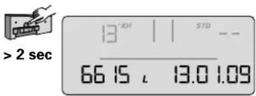
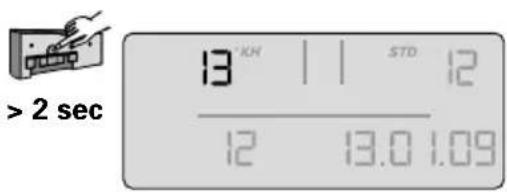
- Press and hold the button (> 4 seconds and < 10 seconds) until the parameter input for the filter system type and size flashes.
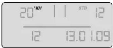
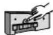
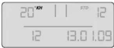
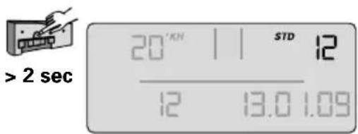
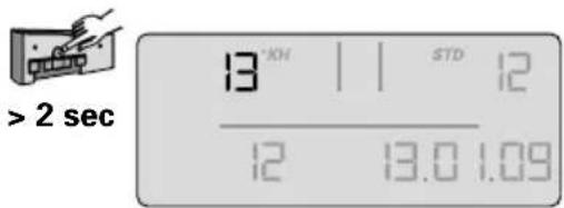
- Press and hold the button (> 2 seconds) until the filter system type (STD, STM, FIN) and corresponding value for the filter system size (04, 06, 12) has been reached.
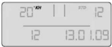
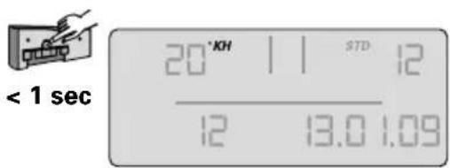
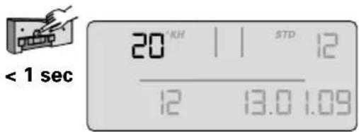
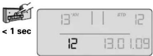
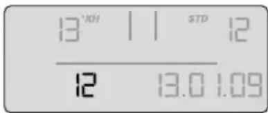
- Press the button once (< 1 second) to access the next parameter input unit of hardness. The unit of hardness flashes.
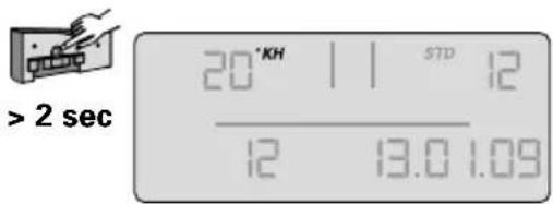
- Press and hold the button (> 2 seconds) until the desired unit of hardness has been selected.
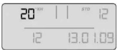
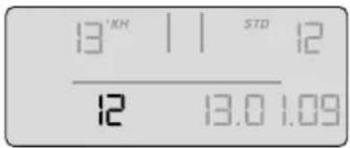
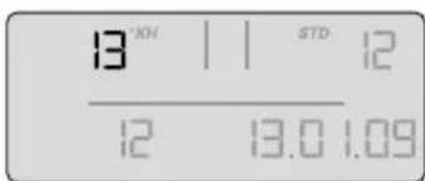
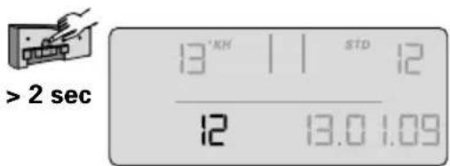
- Press the button once (< 1 second) to access the next parameter input hardness value. The hardness value input flashes.
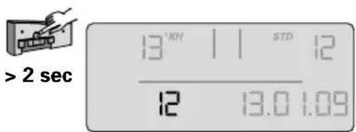
- Press and hold the button (> 2 seconds) until the value for the water hardness rises and keep it pressed until the desired value has been reached.
- Press the button (< 1 second) to access the next parameter input monthly limit. The monthly limit input flashes.
- Press the button (> 2 seconds) and keep it pressed until the desired value has been reached.
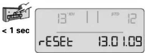
The set parameters can now be accepted.
If you want to accept the parameters, proceed as follows:
- Press the button once (< 1 second) until the message "Reset" appears and flashes.
4 sec

2 sec

< 1 sec

2 sec


< 1 sec

2 sec
< 1 sec

2 sec

< 1 sec
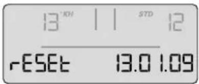
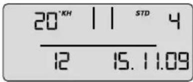
- Press the button once (> 2 seconds) until the total capacity (at 0% bypass) and the current date appear.
2 sec
The set parameters have been accepted.
Note: If no input is made within 30 seconds, the display will return to standby or operating mode without accepting amended parameters.
- Insert the display unit from the front at a height of approx. 10 mm and slide down. The loops on the display part must be inserted in the grooves on the measuring head. Continue with Chapter 5.4 Flushing/Draining for Filter Systems with and without Measuring and Display Unit.
5.3 Bypass Setting
Determining the bypass setting
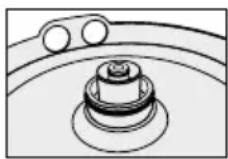
The bypass setting is identified according to the application and the carbonate hardness identified on the basis of the bypass and capacity table (Chapter 7). The bypass is then set on the bypass screw 19 as follows:
Turn the bypass screw ⑲ until the desired bypass (0–3) agrees with the marking.
Caution: Use 6 mm or 7/32" Allen key.
Note: Never overwind the by-pass screw to avoid any damage.
5.4 Flushing/Bleeding Filter Systems with and without Measuring and Display Unit
Note: A 10 litre bucket is required for flushing/draining.
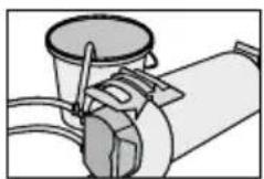
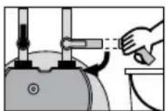
- Position filter system horizontally.
• Completely open flush valve ⑨.
- Fully open the inlet valve ⑦ at inlet hose ⑥ while holding the flush hose in the bucket. Flush with at least 10 litres of water with a minimum volumetric flow of 3 l/min (180 l/h).
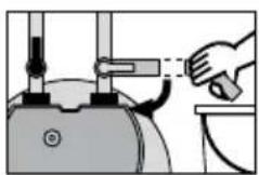
- Close flush valve ⑨, put down filter and empty bucket.
natural_image
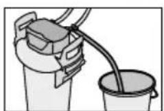
Illustration of a bucket pouring liquid into a bucket (no text or symbols)- Carefully open flush valve ⑨ while holding the flush hose in the bucket. Flush quantity once again with at least 10 litres.
- Close flush valve ⑨.
- Check system for any leaks. - Note installation date of the filter system and the next exchange date on the enclosed sticker and attach it to the pressure vessel.
Note: There is space for several stickers on the pressure vessel. Apply the new sticker with the installation date at the top position.
Note: Filter systems without measuring and display units are now ready for operation.
5.5 Checking initialisation of filter systems with a measuring and display unit
- Bypass setting as a percentage, remaining capacity in litres, capacity bars and the current date must be shown on the display.
Note: If these values are not shown in the display, the filter system must be flushed again (Chapter 5.4) until the values are shown in the display. Filter systems with a measuring and display unit are now ready for operation. Cf. Chapters 10.6 to 10.8.
6 Replacing the Filter Cartridge
Caution: During replacement, carefully examine all dismantled parts! Faulty parts must be exchanged and dirty parts should be cleaned. Read the operating and safety information (Chapter 3) prior to replacement. After the product has been stored and transported at temperatures below 0°C, it must be stored with the original packaging open for at least 24 hours before commissioning at the ambient temperatures for operation stated in Chapter 12.
Filter systems without a measuring and display unit
The filter cartridge must be replaced after 6–12 months and no later than 12 months after commissioning regardless of the level of exhaustion of the filter system. If the capacity of the filter cartridge has already been exhausted (Chapter 7), it must be replaced earlier.
Filter systems with a measuring and display unit
The filter cartridge must be replaced no later than 12 months after commissioning, irrespective of the level of exhaustion of the filter system. If the capacity of the filter cartridge has already been exhausted (Chapter 7), it must be replaced earlier.
If the cartridge is already exhausted, the capacity is indicated as being negative by flashing. No bars are shown in the display.
If the monthly limit for the cartridge has been exceeded, this is indicated by the date flashing.
Resetting the display unit
To operate the display unit, it must be removed from the connecting fittings.
Slide the display housing up approx. 10 mm and pull off the display unit. The display unit is operated using a button on the back of the display unit.
- If this button is pressed (> 10 seconds), the data set on initial installation will be accepted again, and the capacity, bypass setting and input date are all updated.
Note: This automatically sets the monthly limit to 12 months.
Note: If no input is made within 30 seconds, the display will return to standby or operating mode without accepting amended parameters.
Insert the display unit from the front at a height of approx. 10 mm and slide down. The loops on the display part must be inserted in the grooves on the measuring head.
6.1 Removing the Filter Cartridge
- Switch off power supply to the terminal device (remove plug).
- Close inlet valve ⑦ at inlet hose ⑥.
- Place the flushing hose in a bucket and remove pressure from the filter system by opening the flush valve. Catch the escaping water in a bucket.
Note: If the escaping water is more than 1 litre, the inlet valve ⑦ is not completely closed or is blocked with scale.
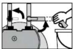
- Stand on the kick loops ⑫ with both feet while opening the pressure vessel lid ③ by pressing the lock ⑮ and turning it anticlockwise as far as it will go.
- Place the pressure vessel lid ③ vertically on both lid handles ⑳. Note: Do not turn the lid horizontally on its head.
- Stand on the kick loops ⑫ with both feet while turning the pressure vessel ① anticlockwise by the mantle handles ⑯ as far as it will go.
• Take your feet off the kick loops ⑫ and press the pressure vessel ⑪ down with both hands on the mantle handles ⑯. - Remove exhausted filter cartridge ② from the pressure vessel ①.
- Place the exhausted filter cartridge ② in the sink with the connection facing down to drain the remaining water (> 5 min.).
- Lock the exhausted filter cartridge ② with the transport protective cap ⑱ of the new filter cartridge and return in the original packaging to the appropriate BRITA address listed on the back of the cover.
6.2 Inserting the Filter Cartridge
- Check the connector seat of the filter cartridge O-ring ② in the pressure vessel lid ① for dirt and damage.
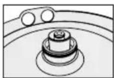
- Check that the O-ring seal of the filter cartridge groove and also check for dirt and damage. ② is correctly seated in the
Note: The cartridge seat has been lubricated with food-safe lubricant at the factory.
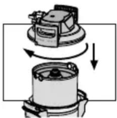
- Place the new filter cartridge ② in the pressure vessel ①.
- Stand on the kick loops ⑫ with both feet, lift the pressure vessel ① turning it clockwise until the mantle handle ⑯ is over the kick loops ⑫.
natural_image
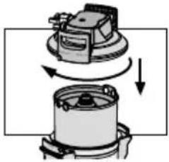
Diagram of a mechanical device with rotating components and directional arrows indicating motion (no text or symbols)- Stand on the kick loops ⑫ with both feet and place the pressure vessel lid ③ on the pressure vessel ①. The positioning of the arrow marking on the lidhandle ⑳ must line up with the "INSERT" groove.
- Press the pressure vessel lid ③ down and turn clockwise until the lock ⑮ engages.
- Switch on power supply to the terminal device (plug).
• To flush and bleed the new filter cartridge ② carry out the steps described under 5.3.
7 Filter Capacity
Use of the PURITY Steam water filter system with integrated measuring and display unit or installation of the BRITA FlowMeter 100–700A is recommended for the precise, continuous control of the degree of filter cartridge exhaustion.
Capacity Table (in litres)
| Carbonate hardness in °KH | PURITY 450 Steam PURITY 600 Steam PURITY 1200 Steam | ||||||||
| Bypass position Bypass position Bypass position | |||||||||
| 0 1 and 2 3 0 1 and 2 3 0 1 and 2 3 | |||||||||
| 4 | 5.633 | 6.134 | 6.760 | 8.833 | 9.619 | 10.600 | 16.530 | 17.999 | 19.836 |
| 5 | 5.633 | 6.134 | 6.760 | 8.833 | 9.619 | 10.600 | 16.530 | 17.999 | 19.836 |
| 6 | 5.633 | 6.134 | 6.760 | 8.833 | 9.619 | 10.600 | 16.530 | 17.999 | 19.836 |
| 7 | 4.829 | 5.258 | 5.794 | 7.571 | 8.244 | 9.086 | 14.169 | 15.428 | 17.002 |
| 8 | 4.225 | 4.601 | 5.070 | 6.625 | 7.214 | 7.950 | 12.398 | 13.500 | 14.877 |
| 9 | 3.756 | 4.089 | 4.507 | 5.889 | 6.412 | 7.067 | 11.020 | 12.000 | 13.224 |
| 10 | 3.380 | 3.680 | 4.056 | 5.300 | 5.771 | 6.360 | 9.918 | 10.800 | 11.902 |
| 11 | 3.073 | 3.346 | 3.687 | 4.818 | 5.246 | 5.782 | 9.016 | 9.818 | 10.820 |
| 12 | 2.817 | 3.067 | 3.380 | 4.417 | 4.809 | 5.300 | 8.265 | 9.000 | 9.918 |
| 13 | 2.600 | 2.831 | 3.120 | 4.077 | 4.439 | 4.892 | 7.629 | 8.307 | 9.155 |
| 14 | 2.414 | 2.629 | 2.897 | 3.786 | 4.122 | 4.543 | 7.084 | 7.714 | 8.501 |
| 15 | 2.253 | 2.454 | 2.704 | 3.533 | 3.847 | 4.240 | 6.612 | 7.200 | 7.934 |
| 16 | 2.113 | 2.300 | 2.535 | 3.313 | 3.607 | 3.975 | 6.199 | 6.750 | 7.439 |
| 17 | 1.988 | 2.165 | 2.386 | 3.118 | 3.395 | 3.741 | 5.834 | 6.353 | 7.001 |
| 18 | 1.878 | 2.045 | 2.253 | 2.944 | 3.206 | 3.533 | 5.510 | 6.000 | 6.612 |
| 19 | 1.779 | 1.937 | 2.135 | 2.789 | 3.037 | 3.347 | 5.220 | 5.684 | 6.264 |
| 20 | 1.690 | 1.840 | 2.028 | 2.650 | 2.886 | 3.180 | 4.959 | 5.400 | 5.951 |
| 21 | 1.610 | 1.753 | 1.931 | 2.524 | 2.748 | 3.029 | 4.723 | 5.143 | 5.667 |
| 23 | 1.470 | 1.600 | 1.763 | 2.304 | 2.509 | 2.765 | 4.312 | 4.695 | 5.175 |
| 25 | 1.352 | 1.472 | 1.622 | 2.120 | 2.308 | 2.544 | 3.967 | 4.320 | 4.761 |
| 28 | 1.207 | 1.314 | 1.449 | 1.893 | 2.061 | 2.271 | 3.542 | 3.857 | 4.251 |
| 31 | 1.090 | 1.187 | 1.308 | 1.710 | 1.862 | 2.052 | 3.199 | 3.484 | 3.839 |
| 35 | 966 | 1.052 | 1.159 | 1.514 | 1.649 | 1.817 | 2.834 | 3.086 | 3.400 |
The bypass position can be adjusted to the local water quality or the machine type.
The following recommendations for bypass settings apply by default:
Position 0: All devices in areas with an extremely high water hardness level (> KH = 22 °KH).
Position 1: Combi ovens and conventional ovens with direct injection system
Position 2: Combi ovens and conventional ovens with boiler system
Position 3: All devices in soft water areas (< KH = 7 °KH).
You can obtain individual recommendations from your BRITA contact.
Note: The stated capacities have been tested and calculated on the basis of common application and machine conditions. External factors (such as fluctuating crude water quality and/or machine type) can cause deviations from this information.
8 Repair
Regularly check the filter system for leaks. Regularly check the hoses for kinks. Bent hoses must be replaced.
The complete filter system must be replaced in rotation after a maximum of ten years. The hoses must be replaced in rotation after a maximum of five years.
Caution: Prior to changing, read the Technical Data (Chapter 12) and the Operating and Safety Information (Chapter 3).
Regularly clean the outside of the filter system with a soft, damp cloth.
Caution: Do not use any substances incompatible with the material (Chapter 3.4) or astringent, abrasive cleaning agents.
9 Query Mode
The following data can be queried in the query mode:
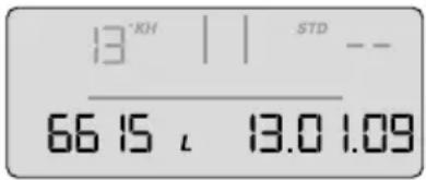
Production data
- Briefly press button once (< 1 second); the following message appears.
ID Level Production Year
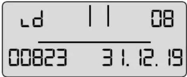
Serial Appliance Number Battery Service Life
Production year: Example 08 = 2008
Device number: consecutive
Useful battery life: Example 31/12/19 = The battery in the display unit will be exhausted on 31/12/19 and the complete filter system has reached its max. usage period.
Total volume meter
- Briefly press button twice (< 1 second); the following message appears.
00 level current data (today)
00 Indicator for current level Filter system size
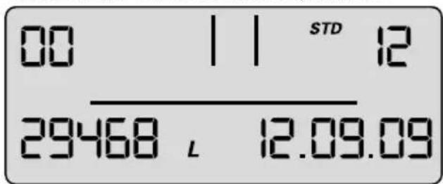
Current dateTotal volume meter
The total volume meter is managed at this level; it counts up from 0 irrespective of the cartridge change.
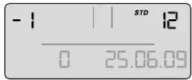
Memory Call-Up
In the Memory Call-Up mode, the data of the last 4 filter cartridges used can be called up. Briefly press button once (< 1 second) until the following message appears:
-1, -2, -3, -4 level – data of the cartridges used before the current one.
Carbonate hardness By-pass
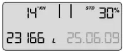
Total meter reading when changing the filter cartridge
alternating
Cartridge indicator Type
Date of inserting the cartridge
At the top left, the indicator for the filter cartridge (-1 for previous filter cartridge) is displayed alternately with the water hardness set and the hardness unit. At the top right, the filter system size is displayed alternately with the bypass setting (display 1 s indicator, 1 s water hardness), at the bottom left, the meter reading when changing the cartridge (-1) and at the bottom right, the installation date of the cartridge.
Meaning: the filter cartridge most recently used was a PURITY 1200 cartridge, the filter cartridge was inserted on 25/06/09 and operated up to a meter reading of 23166 litres.
The water hardness set was 14°KH and the bypass measured was 30%.
The same applies to the cartridge (-2), preceding filter cartridge and the other preceding filter cartridges-3,-4.
Error Messages
Error level E1 indicates whether an error has occurred in blend detection.
E1 is activated as soon as the current bypass is not correctly identified.
The word Start is then displayed together with the date of occurrence.
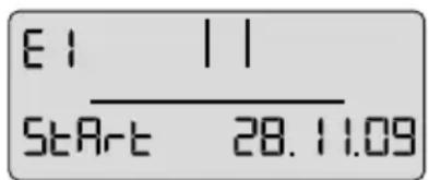
alternating
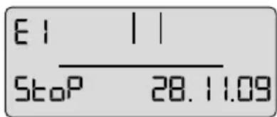
As soon as the current bypass setting is identified correctly again, the error has ended and the Stop date is added. At error level 01 the Stop and Start display alternates every second.
Error level E2 indicates whether and from when until when an error has occurred at the outlet water meter. Display is similar to level E1.
Program Overview
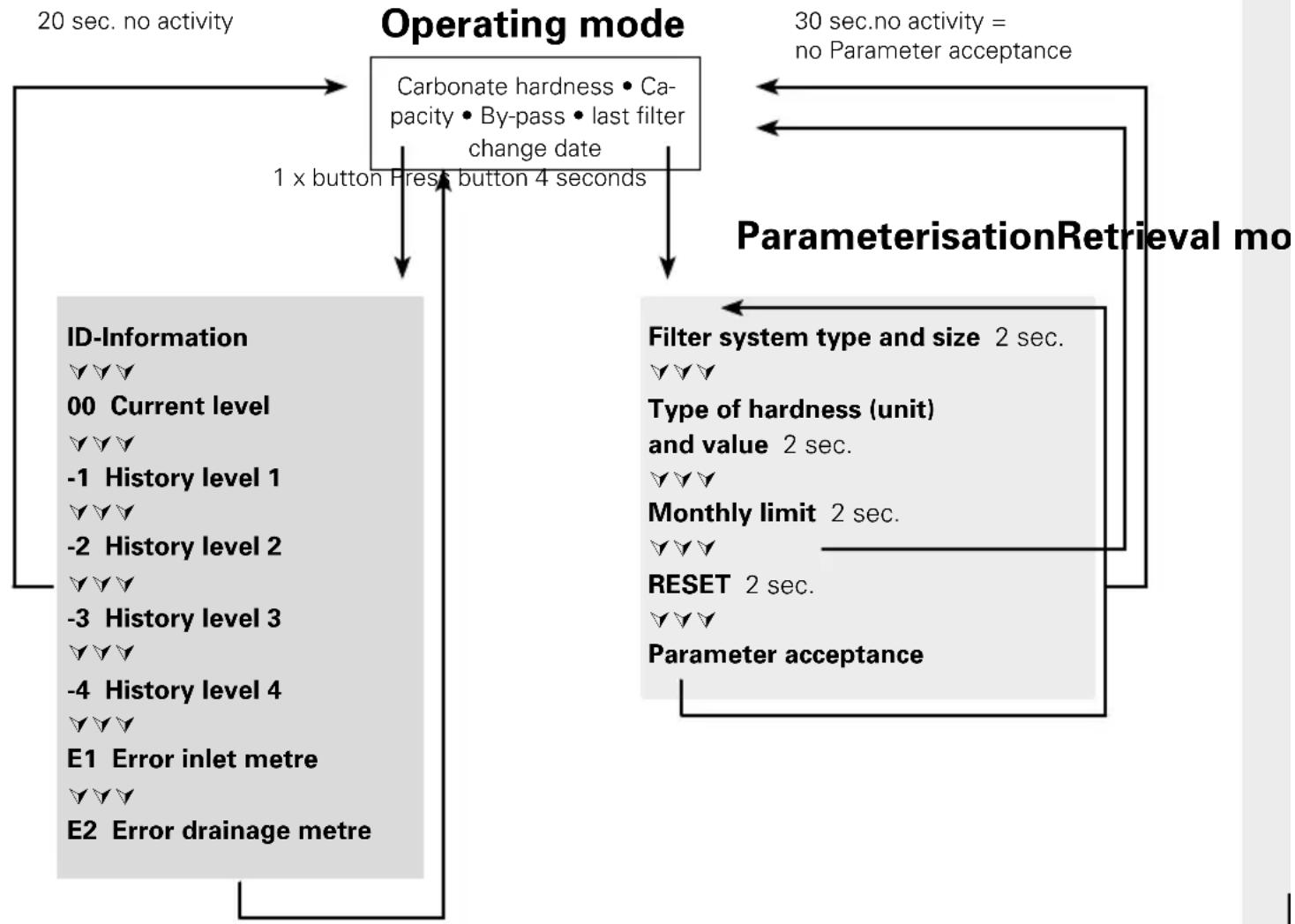
flowchart
graph TD
    A["Operating mode"] --> B["Carbonate hardness • Capacity • By-pass • last filter change date"]
    A --> C["1 x button Press button 4 seconds"]
    A --> D["30 sec.no activity = no Parameter acceptance"]
    A --> E["ParameterisationRetrieval mo"]
    B --> F["ID-Information\n✓ ✓ ✓\n00 Current level\n✓ ✓ ✓\n-1 History level 1\n✓ ✓ ✓\n-2 History level 2\n✓ ✓ ✓\n-3 History level 3\n✓ ✓ ✓\n-4 History level 4\n✓ ✓ ✓\ne1 Error inlet metre\n✓ ✓ ✓\ne2 Error drainage metre"]
    C --> G["Filter system type and size 2 sec.\n✓ ✓ ✓\nType of hardness (unit) and value 2 sec.\n✓ ✓ ✓\nMonthly limit 2 sec.\n✓ ✓ ✓\nRESET 2 sec.\n✓ ✓ ✓\nParameter acceptance"]
    D --> H["End"]
    F --> I["20 sec. no activity"]
    G --> I
    H --> I
10 Troubleshooting
10.1 No water flow
Cause: Water intake closed.
Troubleshooting: Open water intake on the upstream stop valve or inlet valve ⑦ on inlet hose ⑥.
Caution: The following faults may be remedied only by trained and authorised personnel.
10.2 No or low water flow in spite of open water intake
Cause: Mains pressure too low.
Troubleshooting: Check mains pressure.
If the fault continues in spite of adequate mains pressure, check the filter system and filter cartridge and change if necessary.
Caution: Prior to changing, read the Technical Data (Chapter 12) and the Operating and Safety Information (Chapter 3).
10.3 Leak at Screwed Connections
Cause: Screwed connections not fitted correctly.
Troubleshooting: Check mains pressure. Check all screwed connections and mount according to Chapter 4.
If the fault continues, exchange filter system.
Caution: Prior to changing, read the Technical Data (Chapter 12) and the Operating and Safety Information (Chapter 3).
10.4 Leak after Filter Replacement
Cause: O-ring at the filter cartridge is not seated correctly.
Troubleshooting: Check correct seat of the O-ring (Chapter 6.2).
Caution: Prior to dismantling read the data (Chapter 12) and the Operating and Safety Information (Chapter 3).
10.5 No Display Function
Cause: Battery drained.
Troubleshooting: Replace display unit (Order number see Chapter 13).
Note: When replacing the display unit, follow the enclosed manual.
10.6 Data on Display Flashing
Cause: Monthly limit expired or the remaining capacity of the filter cartridge is exhausted (Chapter 5.2).
Troubleshooting: Replace filter cartridge (Chapter 6).
10.7 Bypass setting in the display does not agree with the setting of the bypass screw (cf. 10.8/10.9)
Cause: Filter was not commissioned correctly.
Troubleshooting: Flush filter again (Chapter 5.4). Check data in the display after flushing (Chapter5.5).
10.8 Bypass setting in the display does not agree with the setting of the bypass screw (cf. 10.7/10.8)
Cause: Valve strip of the by-pass setting not set correctly.
Troubleshooting: Flush filter system again and readjust bypass screw (Chapter 5.3)
11 Batter y
The installed battery is designed for a service life of approx. 10 years. The battery and display unit must not be burnt and must not be disposed of in domestic waste.
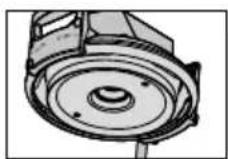
To remove the battery, please proceed as follows:
- Remove the screw on the back of the display unit and open and remove the back of the housing.
- Disconnect the soldered contacts on the battery with side cutters and remove the battery from the bracket.
- Replace the back of the housing on the display unit and tighten the screw.
Dispose of the battery and display unit following
the local environmental guidelines for battery disposal.

12 Technical Data
| Filter system PURITY Steamwith filter cartridge | |||||||
| PURITY 450 Steam PU | RITY 600 Steam PURITY 12 | 00 Steam | |||||
| MDU* | distributor head | MDU* | distributor head | MDU* | distributor head | ||
| Operating pressure 2 bar to max. 6,9 bar | |||||||
| Operating/water temperature 4°C to 30°C | |||||||
| Ambient temperature during | operation 10°C to 40°C | ||||||
| storage/transport -20°C to 50°C | |||||||
| Flow rate with 1 bar pressure loss 400 l/h 500 l/h | 400 l/h 500 l/h | 400 l/h 500 l/h | |||||
| Nominal flow according to Norm | 60 l/h | 60 l/h | 120 l/h | 120 l/h | 120 l/h | 120 l/h | |
| Pressure loss at nominal flow | 0,12 bar | 0,08 bar | 0,36 bar | 0,27 bar | 0,32 bar | 0,24 bar | |
| Empty filter cartridge volume | 3,9 l | 5,8 l | 9,9 l | ||||
| Weight (dry/wet) | 10 kg/12 kg | 12 kg/15 kg | 18 kg/24 kg | ||||
| Comparable capacity according to DIN 18879-1:2007The comparable capacity is a standardised indicator to facilitate comparison of different filters. The comparable capacity is determined under extreme conditions. The usable capacity in practical operation is higher than the comparable capacity and may vary greatly depending on the usage conditions. | |||||||
| Comparable capacity | 2754 l | 4734 l | 9521 l | ||||
| Dimensions complete system (Width/Depth/Height) | 249 mm/222 mm/408 mm | 249 mm/222 mm/520 mm | 288 mm/255 mm/550 mm | ||||
| The bending radii of the inlet and outlet hose 2 m, DN13, 3/4"-3/4" are approx. 130 mm and, depending on the installation orientation and operating space, must be considered in addition to the dimensions of the complete system. | |||||||
| Operating position | The filter system can be operated either vertically or horizontally. | ||||||
| Inlet connection | G 1" | ||||||
| Outlet connection | G 3/4" | ||||||
* with ACS Technology
Comparable capacity according to DIN 18879-1:2007
The comparable capacity is a standardised indicator to facilitate comparison of different filters. The comparable capacity is determined under extreme conditions. The usable capacity in practical operation is higher than the comparable capacity and may vary greatly depending on the usage conditions.
| Comparable capacity according to DIN 18879-1:2007 | |
| PURITY 450 Steam | 2754 litres |
| PURITY 600 Steam | 4734 litres |
| PURITY 1200 Steam | 9521 litres |
13 Order Numbers
Filter system PURITY 450 Steam/PURITY 600 Steam/PURITY 1200 Steam
| Article | Article number |
| PURITY 450 Steam (Complete System with Filter Cartridge) | 1000654 |
| PURITY 600 Steam (Complete System with Filter Cartridge) | 1000245 |
| PURITY 1200 Steam (Complete System with Filter Cartridge) | 1000226 |
| PURITY 450 Steam (Complete System with Filter Cartridge) with Measuring and Display Unit | 1002912 |
| PURITY 600 Steam (Complete System with Filter Cartridge) with Measuring and Display Unit | 1002918 |
| PURITY 1200 Steam (Complete System with Filter Cartridge) with Measuring and Display Unit | 1002923 |
| PURITY 450 Steam Filter Cartridge | 1000653 |
| PURITY 600 Steam Filter Cartridge | 1000252 |
| PURITY 1200 Steam Filter Cartridge | 1000231 |
1 Eléments
natural_image
Diagram of a mechanical device with rotating components and directional arrows indicating motion (no text or symbols)STM 4 = PURITY 450 Steam
STM 6 = PURITY 600 Steam
STM 12 = PURITY 1200 Steam
FIN 6 = PURITY Finest 600
FIN 12 = PURITY Finest 1200

4 sec


2 sec

< 1 sec

2 sec


< 1 sec

2 sec

< 1 sec


2 sec

natural_image
Diagram of a mechanical device with a cup and lever mechanism (no text or symbols)natural_image
Diagram of a mechanical device with rotating components and directional arrows indicating motion (no text or symbols)Cause : montage incorrect des raccords.
natural_image
Diagram of a mechanical device with rotating components and directional arrows indicating motion (no text or symbols)STM 4 = PURITY 450 Steam
STM 6 = PURITY 600 Steam
STM 12 = PURITY 1200 Steam
FIN 6 = PURITY Finest 600
FIN 12 = PURITY Finest 1200

4 sec


2 sec
< 1 sec

2 sec


< 1 sec


2 sec

< 1 sec
2 sec

natural_image
Diagram of a mechanical device with two components and directional arrows indicating motion (no text or symbols)Actuele datum Totaalvolume teller
Filtersysteem PURITY 450 Steam/PURITY 600 Steam/PURITY 1200 Steam
natural_image
Diagram of a mechanical device with rotating components and directional arrows indicating motion (no text or symbols)By-pass in percentuale
STM 4 = PURITY 450 Steam
STM 6 = PURITY 600 Steam
STM 12 = PURITY 1200 Steam
FIN 6 = PURITY Finest 600
FIN 12 = PURITY Finest 1200

4 sec

2 sec


< 1 sec

2 sec

< 1 sec


2 sec
< 1 sec


2 sec

natural_image
Diagram of a mechanical device with rotating components and directional arrows indicating motion (no text or symbols)natural_image
Diagram of a mechanical device with rotating components and directional arrows indicating motion (no text or symbols)STM 4 = PURITY 450 Steam
STM 6 = PURITY 600 Steam
STM 12 = PURITY 1200 Steam
FIN 6 = PURITY Finest 600
FIN 12 = PURITY Finest 1200

natural_image
Diagram of a mechanical device with a cylindrical component and attached tubing (no text or symbols)natural_image
Diagram of a hand operating a mechanical device with rotating components (no text or symbols)natural_image
Illustration of a bucket being inserted into a bucket with a tool (no text or symbols)natural_image
Diagram of a mechanical device with rotating components and directional arrows indicating motion (no text or symbols)natural_image
Diagram of a mechanical device with rotating components and directional arrows indicating motion (no text or symbols)STM 4 = PURITY 450 Steam
STM 6 = PURITY 600 Steam
STM 12 = PURITY 1200 Steam
FIN 6 = PURITY Finest 600
FIN 12 = PURITY Finest 1200

4 sec

2 sec


< 1 sec


2 sec


< 1 sec

2 sec


< 1 sec


2 sec
natural_image
Illustration of a bucket being inserted into a bucket with a pump (no text or symbols)natural_image
Diagram of a mechanical device with rotating components and directional arrows indicating motion (no text or symbols)natural_image
Diagram of a mechanical device with rotating components and directional arrows indicating motion (no text or symbols)STD 4 = PURITY 450 Quell ST STD 6 = PURITY 600 Quell ST STD 12 = PURITY 1200 Quell ST STM 4 = PURITY 450 Steam STM 6 = PURITY 600 Steam STM 12 = PURITY 1200 Steam FIN 6 = PURITY Finest 600 FIN 12 = PURITY Finest 1200

natural_image
Diagram of a mechanical device with rotating components and directional arrows indicating motion (no text or symbols)Filtersystem PURITY 450 Steam/PURITY 600 Steam/PURITY 1200 Steam
| Artikel | Artikel-nummer |
| PURITY 450 Steam (komplet system med filterpatron) | 1000654 |
| PURITY 600 Steam (komplet system med filterpatron) | 1000245 |
| PURITY 1200 Steam (komplet system med filterpatron) | 1000226 |
| PURITY 450 Steam (komplet system med filterpatron) med MAE | 1002912 |
| PURITY 600 Steam (komplet system med filterpatron) med MAE | 1002918 |
| PURITY 1200 Steam (komplet system med filterpatron) med MAE | 1002923 |
| PURITY 450 Steam filterpatron | 1000653 |
| PURITY 600 Steam filterpatron | 1000252 |
| PURITY 1200 Steam filterpatron | 1000231 |
1 Термины
natural_image
Diagram of a mechanical device with rotating components and directional arrows indicating motion (no text or symbols)STM 4 = PURITY 450 Steam
STM 6 = PURITY 600 Steam
STM 12 = PURITY 1200 Steam
(в месяцах)

4 sec


2 sec


< 1 sec


2 sec

< 1 sec

2 sec


< 1 sec

2 sec


2 sec
natural_image
Diagram showing two mechanical components with rotational arrows indicating motion (no text or symbols)clientservices@brita.co.uk
www.brita.co.uk
BRITA GmbH
Office Netherlands
Filter management app
Download our free of charge BRITA Professional FilterManager app and get a reminder for your next fi Iter exchange – automatically, wherever you are.
For smartphone and tablets.
For more information please visit: professional.brita.net/app


A C S
conform


- Deutsch Seite 2–19
- Français Page 37–53
- Begriffsübersicht
- Definition of Terms
- General Information
- Function and Application
- Guarantee Provisions
- Storage/Transport
- Recycling/Disposal
- Operating and Safety Instructions
- Qualified Personnel
- Correct Use
- Liability Exclusion
- Specific Safety Information
- • Production date:
- Safety Assembly Instructions
- Installation
- Delivery Scope
- Assembling the Pressure Vessel and the Pressure Vessel Lid
- Assembly of Inlet and Outlet Hoses
- Commissioning a New Filter
- Bypass Setting for Filter Systems without and with Measuring and Display Unit
- Commissioning the Filter Systems with Measuring and Display Unit
- Representation in operating mode
- Carbonate Hardness
- Bar chart
- Bypass proportion in percentage
- Flow symbol
- Available remaining capacity of the filter cartridge
- Date of the filter commissioning or last filter cartridge change
- Selecting the units of measurement
- Parameterisation
- - Filter system type and size
- • Water hardness unit and water hardness value
- • Monthly limit 2–12
- - Reminder function filter usage period in months
- Operating the display unit
- Parameter input water hardness and filter system size
- Bypass Setting
- Determining the bypass setting
- Flushing/Bleeding Filter Systems with and without Measuring and Display Unit
- Checking initialisation of filter systems with a measuring and display unit
- Replacing the Filter Cartridge
- Filter systems without a measuring and display unit
- Filter systems with a measuring and display unit
- Resetting the display unit
- Removing the Filter Cartridge
- Inserting the Filter Cartridge
- Filter Capacity
- Repair
- Query Mode
- Production data
- Total volume meter
- Memory Call-Up
- -1, -2, -3, -4 level – data of the cartridges used before the current one.
- Error Messages
- Troubleshooting
- No water flow
- No or low water flow in spite of open water intake
- Leak at Screwed Connections
- Leak after Filter Replacement
- No Display Function
- Data on Display Flashing
- Bypass setting in the display does not agree with the setting of the bypass screw (cf. 10.8/10.9)
- Bypass setting in the display does not agree with the setting of the bypass screw (cf. 10.7/10.8)
- Batter y
- Technical Data
- Comparable capacity according to DIN 18879-1:2007
- Order Numbers
- Eléments
- By-pass in percentuale
- Термины
- BRITA GmbH
- Filter management app
Brand : BRITA
Model : Purity 600 Steam
Category : Water filter