55014037 - Smart Home Niko - Free user manual and instructions
Find the device manual for free 55014037 Niko in PDF.
| Product type | Triple vertical wall plate |
| Reference | 550-14037 |
| Brand | Niko |
| Category | Smart home |
| Center distance | 71 mm |
| Orientation | Vertical |
| Material | Epoxy |
| Thickness | 1 mm |
| Connector | Double pin |
| Number of contacts | 2 contacts with 2 openings each |
| Dimensions of connection unit | 51 x 43 x 22 mm (H x W x D) |
| Power supply | 26 Vdc (SELV) |
| Ambient temperature | 0 to 50°C |
| Push button compatibility | Single, double, quadruple or sextuple, with or without LED |
| Main functions | Connection of push buttons to the Niko Home Control bus |
| Installation | On a single flush-mounted box (screws or claws) |
| Extension | Possible by replacing with a larger model |
| Maximum wire cross-section per contact | 2 wires of 0.5 to 1 mm diameter |
| Stripping length | 9 to 10 mm |
| Maintenance | Clean with a soft, dry cloth |
Frequently Asked Questions - 55014037 Niko
User questions about 55014037 Niko
0 question about this device. Answer the ones you know or ask your own.
Ask a new question about this device
Download the instructions for your Smart Home in PDF format for free! Find your manual 55014037 - Niko and take your electronic device back in hand. On this page are published all the documents necessary for the use of your device. 55014037 by Niko.
USER MANUAL 55014037 Niko
natural_image
Four-panel dark square button with small icons (no text or symbols)1xx-52054
Werking
C. Platine murale multiple
D. Bouton-poussoir
E. Plaque de recouvrement
natural_image
Four-panel black square light fixture with four small icons on each panel (no text or symbols)1xx-52054
Fonctionnement
natural_image
3D diagram of a green circuit board with a small component labeled A and B, showing internal wiring or connections (no text or symbols beyond labels)550-14110
natural_image
Four-panel black square with four white icons on each side, arranged in a 2x2 grid (no text or symbols)1xx-52054
Funktionsweise
5. Wall-mounted printed circuit boards and push buttons
5.1. Wall-mounted printed circuit boards
Description
A wall-mounted printed circuit board includes all the electrical and mechanical components required to connect one or several push buttons to the Niko Home Control installation. Niko offers horizontal, vertical, single or multiple printed circuit boards. Choose the type of printed circuit board depending on the number of action buttons required and on a horizontal or vertical assembly. The printed circuit board can be easily replaced by a larger one at a later stage if the need arises to expand the installation.
Reference codes
550-14020: double wall-mounted printed circuit board (centre distance 71 mm, horizontal)
550-14021: double wall-mounted printed circuit board (centre distance 60 mm, vertical)
550-14027: double wall-mounted printed circuit board (centre distance 71 mm, vertical)
550-14030: 3-fold wall-mounted printed circuit board (centre distance 71 mm, horizontal)
550-14031: 3-fold wall-mounted printed circuit board (centre distance 60 mm, vertical)
550-14037: 3-fold wall-mounted printed circuit board (centre distance 71 mm, vertical)
550-14040: 4-fold wall-mounted printed circuit board (centre distance 71 mm, horizontal)
550-14090: connection unit for multiple wall-mounted printed circuit board
550-14110: single wall-mounted printed circuit board with connector
550-14115: single wall-mounted printed circuit board with bridge
450-00067: set of claws for wall-mounted printed circuit board
450-00068: set of claws for connection unit
Installation
Connecting single wall-mounted printed circuit boards
text_image
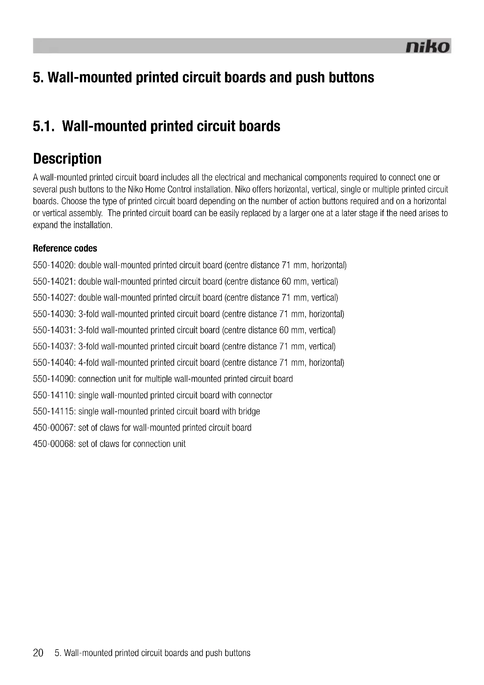
A B 550-14110A. Double plug-in connector
B. Two contacts with two openings each
The double plug-in connector is used for connecting the bus cable to the wall-mounted printed circuit board and for establishing a connection to the next control element. It has two contacts with two openings each.
To connect single wall-mounted printed circuit boards, you connect the bus using two wires from the bus cable. Connect each wire separately to one of the contacts. Each contact is marked by the letter B.
The wall-mounted printed circuit board is now connected. Use the other opening of the contact to establish a connection to the next control element if required.

- Strip the wires of the bus cable 9 - 10 mm.
- A maximum of two wires with a diameter of 0.5 - 1 mm each can be connected per contact.
Connecting multiple wall-mounted printed circuit boards
You need one connection unit for each multiple wall-mounted printed circuit board you wish to connect. Connection units are available separately. The connection unit includes a double plug-in connector, which allows you to connect the bus cable and establish a connection to the next control element. The connector has two contacts with two openings each.
To connect multiple wall-mounted printed circuit boards:
1 Connect two wires of the bus cable to the contacts of the connection unit.
The connection unit is now connected. Use the other opening of the contact to establish a connection to the next control element if required.

- Strip the wires of the bus cable 9 - 10 mm.
- A maximum of two wires with a diameter of 0.5 - 1 mm each can be connected per contact.
2 Remove the transparent tape from the wall-mounted printed circuit board where the connection unit will be mounted. This connection unit is mounted closest to the flush-mounting box.
3 Press the connection unit onto the wall-mounted printed circuit board until it clicks into place. Secure the connection unit using two screws.
Assembly

text_image
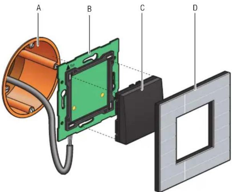
A B C DInstallation diagram for single wall-mounted printed circuit boards
A. Single flush-mounting box (not a Niko product)
B. Single wall-mounted printed circuit board
C. Push button
D. Flush surround plate
text_image
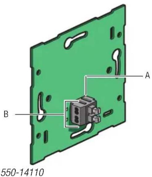
A B C D EA. Single flush-mounting box (not a Niko product)
B. Connection unit
C. Multiple wall-mounted printed circuit board
D. Push button
E. Flush surround plate
Installation diagram for multiple wall-mounted printed circuit boards
To mount the wall-mounted printed circuit board, press the unit onto a single flush-mounting box until it clicks into place. Secure using screws.
Use a set of claws if no screw holes are provided in the flush-mounting box. Sets of claws for single and multiple wall-mounted printed circuit boards are available separately.
Secure the sides of larger wall-mounted printed circuit boards onto the wall using the screw holes provided in the wall-mounted printed circuit board.
Use a single wall-mounted printed circuit board with metal bridge on very uneven walls or in combination with other Niko flush-mounting units with bridge The bridges can be clicked together.
Technical data
• wall-mounted printed circuit board material: epoxy
- material thickness: 1 mm
- one double connector
- connection unit dimensions: 51 x 43 x 22 mm (HxWxD)
5.2. Generic push buttons
Description
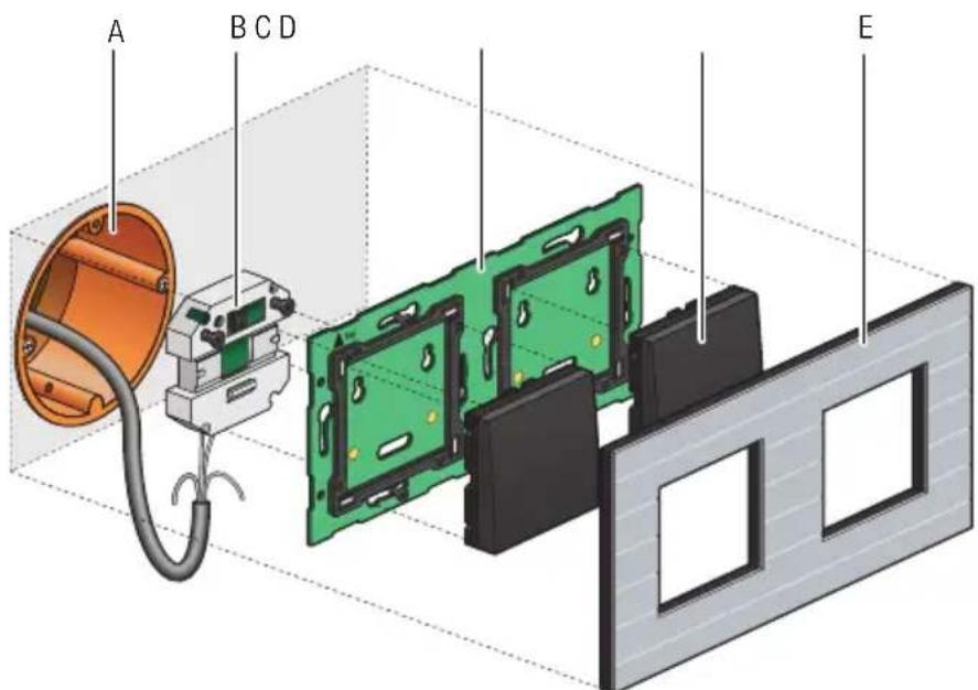
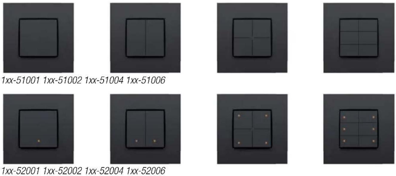
Single, double, 4-fold and 6-fold push buttons are available with or without status LED. These push buttons include one or more action buttons that allow the resident to operate the Niko Home Control functions.
Overview
Operation
Each action button can either control a light point or a light circuit, dim a dimmable light point or activate a mood setting. A mood setting is a combination of pre-programmed output settings.
Action buttons with status LED will indicate the status of their respective output. Using the programming software, you can program the LEDs to light up when the output is either activated or deactivated.
Installation
The control element consists of a push button and one or more action buttons. Complete the installation using the flush surround plate of your choice from our series Niko Pure, Niko Intense or Niko Original.
text_image
A B C DA. Single flush-mounting box (not a Niko product)
B. Single wall-mounted printed circuit board
C. Push button
D. Flush surround plate
Installation diagram for single wall-mounted printed circuit boards
To mount the push button, press the unit onto a Niko Home Control wall-mounted printed circuit board until it clicks into place. The push button is now secure. The functions of the action buttons can be assigned while programming the installation by linking each function to the unique address of each action button during the addressing phase. This information is then stored in the controller.
Technical data
- resting potential: 26 Vdc (SELV, safety extra-low voltage)
- ambient temperature: 0 - 50°C
5.3. Specific push buttons
5.3.1. Push buttons for dimming
Description
Push buttons for dimming are available in a single-row (three action buttons) or double-row (six action buttons) configuration, with or without status LED. They allow the resident to operate one or two light points respectively, or groups of light points, via the Niko Home Control installation.
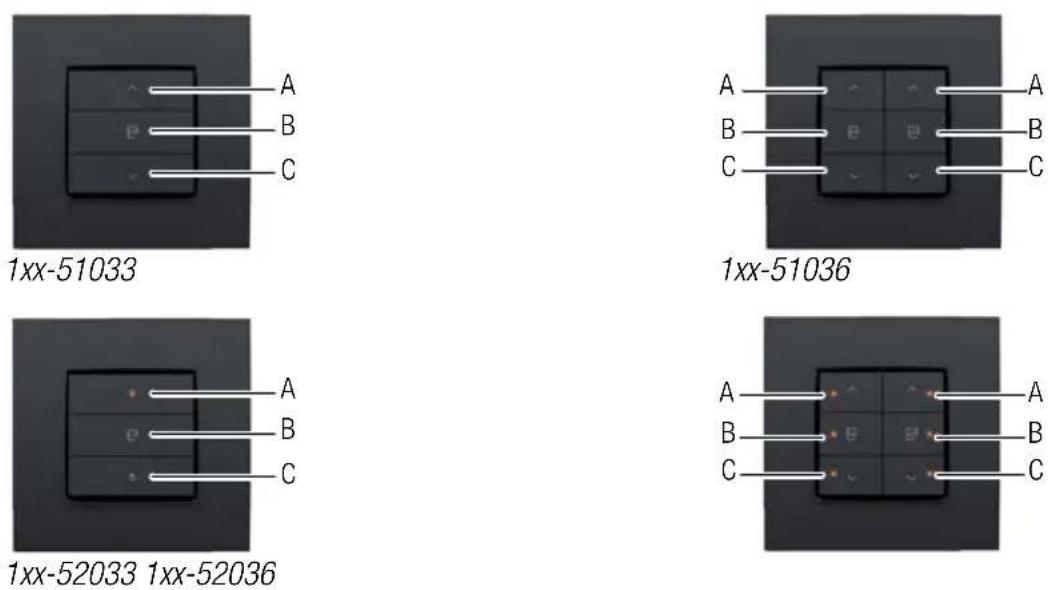
Overview
text_image
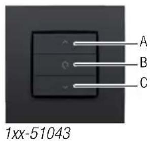
A B C 1xx-51043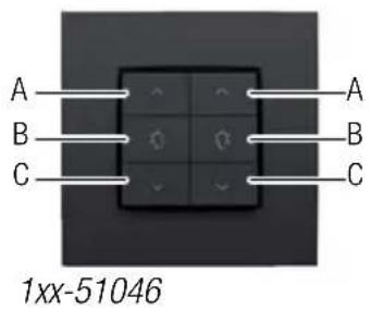
text_image
A B C 1xx-51046 A B C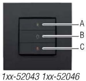
text_image
A B C 1xx-52043 1xx-52046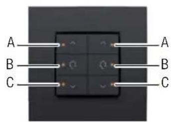
text_image
A B C A B COperation
The specific action buttons on each push button are arranged in groups of three. Each group consists of the following buttons: "A", "B" and "C".
Action buttons with status LED will indicate the status of their respective output. Using the programming software, you can program the LEDs to light up when the output is either activated or deactivated.
The table below provides an overview of all action button functions.
| ‘Before’ status Action ‘After’ status | ||
| Light off | Briefly press "A" (< 0.4 s) | “Memory off” means the light intensity level will reach 100%. “Memory on” means the light intensity level will return to the previous setting, which is the last used light intensity level prior to the dimmer being switched off. The “Memory off” or “Memory on” option can be selected during the programming phase of the installation. |
| Light off | Briefly press "B" (< 0.4 s) | Preference setting (standard 50%) |
| Light off | Briefly press "C" (< 0.4 s) | The light is switched on. The light intensity level remains at the lowest setting. |
| Light off | Press and hold "A" (≥ 0.4 s) | The light intensity level will increase until the button is released or until the maximum level is reached. |
| Light off Press and hold "B" (≥ 0.4 s and < 3 s) | Preference setting (standard 50%) | |
| Light off | Press and hold "B" (> 3 s) | The current light intensity level is now saved as the new preference setting. |
| Light off | Press and hold "C" (≥ 0.4 s) | The light is switched on. The light intensity level remains at the lowest setting. |
| Light on | Briefly press "A" (< 0.4 s) | The light intensity level will reach 100%. |
| Light on | Briefly press "B" (< 0.4 s) | Preference setting (standard 50%) |
| Light on | Briefly press "C" (< 0.4 s) | The light is switched off. |
| Light on | Press and hold "A" (≥ 0.4 s) | The light intensity level will increase until the button is released or until the maximum level is reached. |
| Light on | Press and hold "B" (< 3 s) | Preference setting (standard 50%) |
| Light on | Press and hold "B" (> 3 s) | The current light intensity level is now saved as the new preference setting. |
| Light on | Press and hold "C" (≥ 0.4 s) | The light intensity level will decrease until the button is released or until the minimum level is reached. |
Installation
See Installation on page 24.
Technical data
- resting potential: 26 Vdc (SELV, safety extra-low voltage)
- ambient temperature: 0 - 50°C
5.3.2.Push button for ventilation
Description
The push button for ventilation allows the resident to operate the central ventilation system (type C or D) via the Niko Home Control installation.
Overview
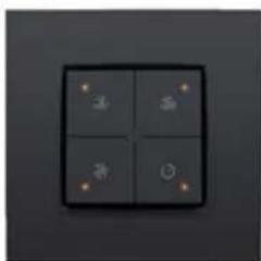
natural_image
Four square dark gray tiles with small white icons on top and bottom, arranged in a 2x2 grid (no text or symbols)1xx-52054
Operation
The push button includes four action buttons: one for each setting of the central ventilation system (low, medium, high) and one that activates the boost function. When the boost function is activated, the ventilation system will operate at the highest setting during a preset amount of time before returning to the previous setting.
Installation
See Installation on page 24.
Technical data
- resting potential: 26 Vdc (SELV, safety extra-low voltage)
- ambient temperature: 0 - 50°C
5.3.3.Push buttons for motor control
Description
Push buttons for motor control are available in a single-row (three action buttons) or double-row (six action buttons) configuration. They allow the resident to operate the motors of one or two groups of roll-down shutters, sun blinds or venetian blinds integrated in the Niko Home Control installation.
Overview
Operation
The specific action buttons on each push button are arranged in groups of three. Each group consists of the following buttons: "A", "B" and "C".
Action buttons with status LED will indicate the status of their respective output. Using the programming software, you can program the LEDs to light up when the output is either activated or deactivated.
The table below provides an overview of all action button functions.
| ‘Before’ status Action ‘After’ | status | |
| No motion | Briefly press "A" (< 0.4 s) | Fully open / upward motion |
| No motion | Briefly press "B" (< 0.4 s) | Preference setting (standard 50%) |
| No motion | Briefly press "C" (< 0.4 s) | Fully closed / downward motion |
| No motion | Press and hold "A" (≥ 0.4 s) | Opens / upward motion until the button is released. |
| No motion | Press and hold "B" (> 3 s) | The current position is now saved as the new preference setting. |
| No motion | Press and hold "C" (≥ 0.4 s) | Closes / downward motion until the button is released. |
| In motion | Briefly press "A" (< 0.4 s) | Stops |
| In motion | Briefly press "B" (< 0.4 s) | Stops |
| In motion | Briefly press "C" (< 0.4 s) | Stops |
| In motion | Press and hold "A" (≥ 0.4 s) | Stops |
| In motion | Press and hold "B" (≥ 0,4 s) | Stops |
| In motion | Press and hold "C" (≥ 0.4 s) | Stops |
Installation
See Installation on page 24.
Technical data
- resting potential: 26 Vdc (SELV, safety extra-low voltage)
- ambient temperature: 0 - 50°C
natural_image
Four-panel grid with small icons (hair, butterfly, bird, mouse) on dark background, no text or symbols present1xx-52054
Prevádzka
natural_image
Four-panel dark square light fixture with four small icons on top, arranged in a 2x2 grid (no text or symbols visible)1xx-52054