
WSP 2010 - Heating AEG - Free user manual and instructions
Find the device manual for free WSP 2010 AEG in PDF.
| Product type | Electric heat accumulator |
| Brand | AEG |
| Model | WSP 2010 |
| Width (mm) | 605 |
| Depth X (mm) | 415 |
| Weight with stones (kg) | 118 |
| Power supply | Three-phase 400 V AC, 50 Hz (3/N/PE) |
| Nominal power (kW) | 2.0 |
| Measuring charge (kWh) | 16.0 |
| Maximum permitted charge (kWh) | 17.0 |
| Main functions | Heat accumulation, manual or automatic charge regulation, emission by fan controlled by room thermostat (optional), centralized management possible |
| Charge setting | 4-position selector (0, 1/3, 2/3, full charge) or automatic via centralized management module |
| Emission setting | AEG room thermostat (optional) for fan modulation |
| Routine maintenance | Regular cleaning of the air inlet grille filter; clean the cold appliance with a damp cloth, without abrasive products |
| Periodic maintenance | Inspection every 2 years of the ventilation duct by a specialist; safety device check no later than 10 years after first commissioning |
| Safety | Minimum distances to respect (outlet grille 500 mm, sides 70-100 mm, cover 40-100 mm); do not cover, do not dry laundry; temperature limiter and overheating regulators |
| Spare parts and accessories | Wall-mounted or built-in room thermostat, centralized charge management module, auxiliary heating, floor mounting base |
| Repairability | Interventions reserved for an approved specialist; wiring diagrams provided in the manual |
| General information | User and installation manual included; warranty according to country of purchase; recycling of packaging and appliance at end of life |
Frequently Asked Questions - WSP 2010 AEG
User questions about WSP 2010 AEG
0 question about this device. Answer the ones you know or ask your own.
Ask a new question about this device
Download the instructions for your Heating in PDF format for free! Find your manual WSP 2010 - AEG and take your electronic device back in hand. On this page are published all the documents necessary for the use of your device. WSP 2010 by AEG.
USER MANUAL WSP 2010 AEG
WSP 2010, WSP 3010,
WSP 4010, WSP 5010,
WSP 6010, WSP 7010
Wärmespeicher
Standard-Baureihe
WSP 2010, WSP 3010,
WSP 4010, WSP 5010,
WSP 6010, WSP 7010
Electric Storage Heaters
Standard Series
Operating and Installation instructions
WSP 2010, WSP 3010,
WSP 4010, WSP 5010,
WSP 6010, WSP 7010
WSP 2010, WSP 3010,
WSP 4010, WSP 5010,
WSP 6010, WSP 7010
Warmte accumulator
standaard série
1. Operating instructions
For the user
1.1 Technical description 21
1.2 Operation 21
1.3 Safety instructions 22
1.4 Care and maintenance 22
1.5 Important note 23
What to do when .? 23
2. Installation Instructions
For the filter
2.1 Technical data 24
2.2 Technical description 25
2.3 Rules and regulations 26
2.4 Installation 27
2.5 Unit installation 27
2.6 First-lime operation 31
2.7 Repair, conversion of unit 31
2.8 Transfer 31
3.Environment and recycling 34
Nederlandss
Inhoudsopgave
1. Operating Instructions
1.1 Technical Description
Storage heaters store electrically generated heat during low-cost electricity tariff periods (depending on the electricity supply company, mainly during the night hours). This is then discharged according to the desired room temperature as hot air by a fan and to a small extent through the surface of the heater.
1.2 Operation
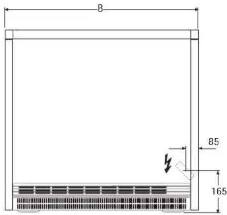
The unit is operated by the control panel (1) on the right side wall (fig. 1).
1.2.1 Heat Storage
The degree of heat storage (charging) is determined by the selector knob (fig. 17).
A distinction needs to be made here between operation of the storage heater with or without central weather-controlled charging control unit (is in the sub-distributor).
If there is no central, weather-controlled charging control unit (manual operation, fig. 18), the selector knob should be set as follows:
- = no charging
1 = Transitional period (Spring/Autumn) - corresponds to about 1/3 full charge
2 = Mild Winter days - corresponds to about 2/3 full charge
3 = Winter days - corresponds to full charge
After a short while you will soon have the necessary experience to find the right setting every time.
If there is a central, weather-controlled charging control unit (automatic operation), the selector knob should be set to position 3. The weather-controlled charging control unit then takes care of the right charging. For varying control of individual storage heaters, the charging volume can be adapted manually with the selector knob even when a charging control unit is available.
1.2.2 Heat Discharge
The heat discharge is controlled by a wall-mounted or integrated AEG room temperature regulator (special accessory).
The desired room temperature must be set at the room temperature regulator which then controls the heat discharge automatically with the fan so that the set room temperature is kept constant.
On very cold days it is advisable to leave the room temperature regulator switched on during long periods of absence (several days) to keep the temperature at about 10^ for example so that the building or room does not go cold (protection against frost).
1.3 Safety Instructions
The unit must not
- be operated in rooms where there is a risk of fire or explosion due to chemicals, dust, gases or fumes;
- be operated in the immediate vicinity of pipes or containers which carry or contain inflammable or explosive substances;
- be operated when the minimum distances from adjacent object surfaces are not kept.
- This unit must only be installed (electrical installation), commissioned and maintained by an authorised expert according to these instructions.
- The unit must on no account be operated when work on floors such as laying, sanding, sealing, cleaning with petrol and caring (spray, wax) and similar is being performed. Then the room must be adequately aired before charging.
- The heater's casing surfaces and the air outlet grille can heat up to temperatures above 80^ . Therefore no inflammable, ignitable or heat insulating objects or materials such as washing, blankets, newspapers, containers of floor wax or petrol, aerosol cans and similar may be placed on or in the immediate vicinity of the heater. Washing must never be hung over the heater to dry. Danger of catching fire!
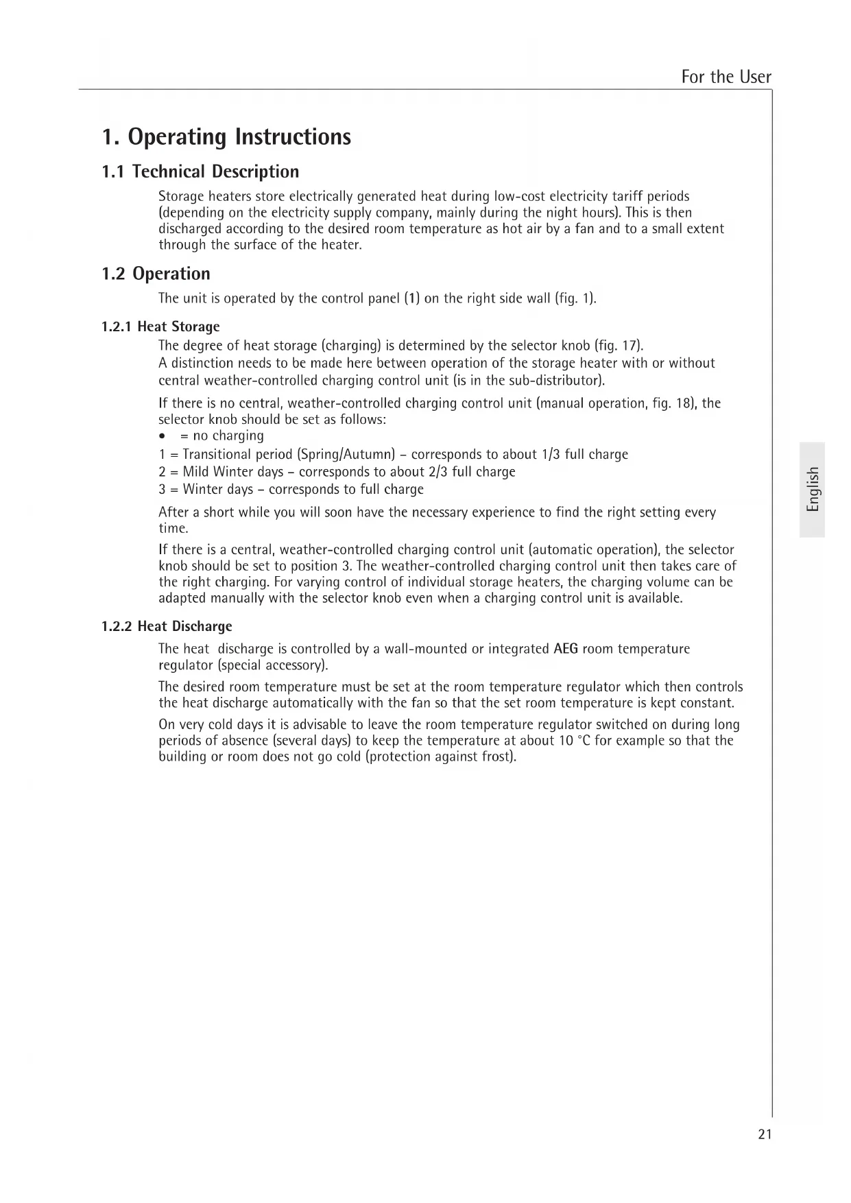
- The following minimum distances must be kept from the heater by all kinds of objects, e.g. furniture, curtains and textiles or other flammable and non-flammable materials especially from the air outlet grid (fig. 2): to the air outlet grille 500mm
from the right side wall (for installation clearance) 100mm
from the left side wall 70 mm
from the left side wall with two storage heaters next to one another 100 mm
from the cover (e. g. window ledge) 40mm
from the cover (curtains, inflammable materials) 100mm
The hot air must be able to discharge unhindered (fig. 19)!
- The label enclosed with these operating and installation instructions "Do not place objects on or lean them against the heater" must be affixed well visibly on the top of the heater in commercially used rooms such as hotels, holiday homes, schools etc.
1.4 Care and Maintenance
If slight brown discoloration of the unit housing should occur, this should be rubbed off immediately with a soft cloth.
The device should be cleaned cold with normal cleaners.
Abrasive and aggressive cleaners should be avoided.
Do not spray cleaning spray into the air vents.
The ventilation duct behind the air outlet grille (5) should be checked by a specialist every two years. Slight dirt deposits may accumulate here.
We recommend that you have the inspection and control elements checked during regular maintenance. Safety, inspection and control elements as well as the entire charging and discharge control system should be checked by a specialist 10 years after first commissioning at the latest.
1.4.1 Cleaning the Fluff Screen (fig. 3)
The fluff screen (7) located in the air inlet grille (6) must be cleaned regularly, so that fault-free discharging of the storage heater is guaranteed.
The fans switch off when the fluff screen is blocked.
Proceed as follows to clean the fluff screen.
- Press the air inlet grille (6) down slightly on both sides, tip forward at the front and remove;
- Press the fluff screen out of the grille with a screwdriver for example and clean with a brush, vacuum cleaner or similar;
Replace the fluff screen in the grille and snap in the lugs.
- Place the air inlet grille at an angle on the lugs in the unit base and snap in under the air outlet grille by pressing lightly (fig. 16).
1.5 Important Note

Keep these instructions in a safe place, pass on to the new owner in case of a change of ownership. Make them available to the specialist in the case of repair work.
What to do when...?
| For the User | For the specialist | |
| ·the storage heater does not get hot | Check whether ... ... the selector knob is set to position 3. ... the corresponding fuses in your fuse box are defective or the FI switch has switched off. Eliminate the cause! | Check whether ... ... the control of the heating element contactor is OK. ... there is a voltage at terminals L1/L2/L3. ... whether the safety temperature limiter (F1) has triggered. |
| If the following day the storage heaters have still not heated up, call a specialist. | ||
| ·the storage heater housing should get extraordinarily hot even in mild weather | Check whether ... ... the fan can be switched on with the room temperature regulator. If not, call a specialist. | Check whether ... ... the room temperature regulator has switched on and voltage is applied at terminal LE. ... the fans are turning. ... the safety temperature regulator "(N5, see page 3, fig. 1) in the air outlet has switched off. ... the control signal Z1 of the charging control unit is applied at terminal A1/Z1 in the |
| ... the fluff screen in the air inlet grille is blocked. Eliminate cause as described in section 1.4.1! |
2. Installation Instructions
2.1 Technical Data
The unit must be installed and connected by a specialist under consideration of these installation instructions.
| WSP 2010 | WSP 3010 | WSP 4010 | WSP 5010 | WSP 6010 | WSP 7010 | |
| Width "B" m | 605 | m780 | 955 | 1130 | 1305 | 1480 |
| Weight (with storage blocks) kg | 118 | 169 | 220 | 271 | 322 | 373 |
| Distance "X" m | 415 | m 590 | 765 | 940 | 1115 | 1290 |
| Connection | * | 3/N/PE ~ 50 Hz 400 V | ||||
| Power kW | 2.0 | 3,0 | 4.0 | 5.0 | 6.0 | 7.0 |
| Reference charging kWh | 16.0 | 24.0 | 32.0 | 40.0 | 48.0 | 56.0 |
| max. charging PH kWh | 17.0 | 25.5 | 35.0 | 42.0 | 51.0 | 61.5 |
| Storage blocks | ||||||
| Number of packages (blocks) pcs. | 6 (12) | 9 (18) | 12 (24) | 15 (30) | 18 (36) | 21 (42) |
| Block weight kg | 85 | 128 | 170 | 213 | 256 | 298 |
| Control resistance kΩ | 3.4 | 3.4 | 3.4 | 3.4 | 3.4 | 3.4 |
| Supplementary heating (special accessories) | ||||||
| Power kW | 0.35 / 0.5 | 0.5 / 0.8 | 0.8 / 1.0 | 1.0 / 1.2 | 1.2 / 1.5 | 1.5 / 1.7 |
- WSP 2010 also with 1/N/PE ~ 50 Hz 230 V connectable
2.2 Technical Description (page 3, fig. 1)
1 Control panel
2 Cover
3 Right side wall
4 Front wall
5 Air outlet grille
6 Air inlet grille
7 Fluff screen
8 Inside front wall
9 Storage blocks
10 Cover plate
11 Thermal insulation
12 Floor thermal insulation
13 Mixing air flap
14 Air duct
15 Cable duct
16 Air guidance assembly
17 Heating element
18 Fan
19 Safety temperature regulator - discharging (N5)
20 Safety temperature regulator - charging (N4)
21 Safety temperature limiter (F1)
2.2.1 Function Principle
The storage blocks are heated up by the heating elements between the rows of storage blocks.
Charging is set continuously with the charging control unit (selector knob fig. 17)
Start and duration of the charging time are determined by the responsible electricity supply company.
Two built-in safety temperature regulators (19, 20) and a safety temperature limiter (21) prevent overheating of the unit. Whilst the safety temperature regulators switch on again automatically, the safety temperature limiter must be switched back on by the technician by pressing in the knob in the middle of the limiter after eliminating the cause of the error.
The heat stored in this way is then discharged with the aid of a fan, also partly through the heater surface. In this case, the room air is sucked in through the air inlet grille (6) by the fan (18) and blown through the air ducts of the storage blocks (9) which heats them up.
Before being output through the air outlet grille (5) the hot air generated in this way is mixed via two mixing air flaps with colder room air so that the emitted air does not exceed the maximum permissible temperature. The position of the mixing air flap and thus the mixing ratio of the air is controlled by a bi-metal controller.
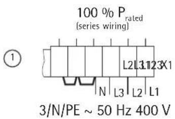
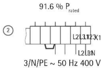
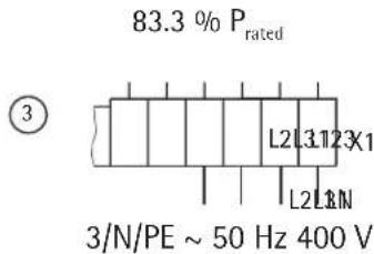
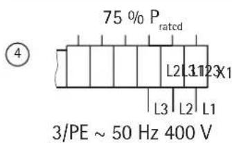
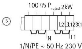
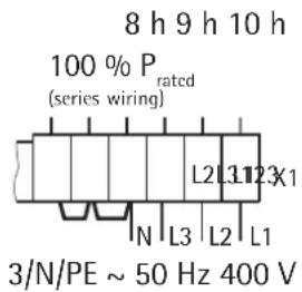
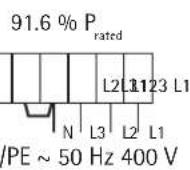
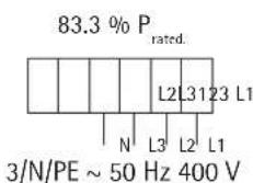
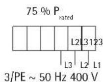
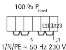
2.2.2 Reducing the Output
By moving or removing bridges at the terminals, the connection rating, factory wired to 100% can be reduced by three levels (see the table).
The dimensioning of the line cross sections and the fusing should correspond to the maximum possible output of the unit.

A single-phase connection may be made according to the "Technical connection conditions" of the energy supply company only up to 2kW (WSP 2010).
| Power variants kW | 8h heating elements (series) | 6h heating element fitting set (special accessory) | |||||||
| Connection variants | ① 100 % | ② 91.6 % | ③ 83.3 % | ④ 75 % | ⑤ 100 % | ① 100 % | ② 91.6 % | ③ 83.3 % | ④ 75 % |
| Model | |||||||||
| WSP 2010 | 2.0 | 1.83 | 1.67 | 1.50 | 2.0 | 2.7 | 2.47 | 2.25 | 2.03 |
| WSP 3010 | 3.0 | 2.75 | 2.50 | 2.25 | - | 4.1 | 3.75 | 3.42 | 3.07 |
| WSP 4010 | 4.0 | 3.66 | 3.33 | 3.00 | - | 5.5 | 5.04 | 4.58 | 4.13 |
| WSP 5010 | 5.0 | 4.58 | 4.16 | 3.75 | - | 6.5 | 5.96 | 5.42 | 4.88 |
| WSP 6010 | 6.0 | 5.50 | 5.00 | 4.50 | - | 8.1 | 7.42 | 6.75 | 6.08 |
| WSP 7010 | 7.0 | 6.42 | 5.83 | 5.25 | - | 9.0 | 8.24 | 7.5 | 6.75 |
2.3 Rules and Regulations
Pay attention to the packing slip!
The national building and garage regulations must be taken into account.
- The installation area must have a sufficient floor load capacity.
In case of doubt a building surveyor should be consulted (for weights of the storage heaters, see "Technical Data").
The minimum distance from adjacent object surfaces must be kept (figs. 2 and 2a).
- All electrical connection and installation work must be performed in accordance with the VDE regulations (0100), the regulations of the electricity supply company responsible and the pertinent national and regional regulations.
- The device must be disconnectable from the mains at all poles by an supplementary device with a disconnection distance of at least 3mm . Contactors, fuses and similar can be connected for this.
- A later increase in the output must be approved separately by the responsible electricity supply company. Failure to notify the electricity supply company of the increase in the output constitutes a breach of the electricity supply contract.
- The operating equipment must be designed for the rated consumption of the units.
The unit's rating plate must be observed!
The specified voltage must match the rated voltage.
- The unit must be fixed to meet the VDE standing safety requirement.
2.4 Installation Site
The unit may not
- be operated in rooms where there is a risk of fire or explosion due to chemicals, dust, gases or fumes;
- be operated in the immediate vicinity of pipes or containers which carry or contain inflammable or explosive substances;
- be operated when the minimum distances from adjacent object surfaces are not kept.
In rooms in which exhaust fumes, oil and petrol smells occur, the unpleasant smell may linger and could possibly cause soiling.
Installation wall
Check whether a wall of sufficient stability is available for fastening the unit.
If no suitable fastening wall is available, the unit must be fixed to the floor (screwed directly to the floor or to another floor console [special accessory]).
Floors
The standing surface of the unit must be level and sufficiently stable so that the housing is not deformed.
A temperature resistance of the fastening wall of at least 85^ and of the floor of at least 80^ must be ensured. The units can be placed on any conventional floor but changes may occur in the rail area on PVC, parquet and long pile carpeted floors under the influence of pressure and temperature. In this case heat-resistant underlay tiles must be used (to be provided on site).
2.5 Unit Installation (fig. 3-14)
The storage heater must be secured by a wall or floor fixture (fig. 8) to meet the VDE standing safety requirement.
The screws and plugs necessary for fixing the unit are not included in delivery. They must be selected and provided by a qualified fitter depending on the respective wall material.
Wall fastening
There is a hole in the unit rear wall in the vicinity of the switching area through which a suitable screw can be inserted for fixing to a sufficiently stable wall (fig. 8).
Before fixing the unit, make sure that the permissible minimum distances from adjacent objects are kept.
Floor fastening
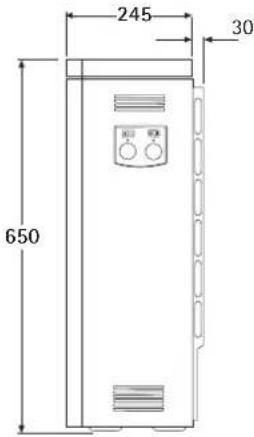
The unit is fixed to the floor by screwing the bottom of the unit to the floor through 4.9mm holes (see "Technical Data", page 9 for dimensions).
This type of fixture is only possible with the air outlet and inlet grilles and the fan drawer removed.
2.5.1 Unit Installation (fig. 3-6)
- Press the air inlet grille (6) down slightly on both sides, tip forward at the front and remove. Unscrew both screws at the air outlet grille (5) and remove the grille (fig. 3).
- Loosen the front wall (4) with 2 screws at the bottom (inside threaded holes), lift the front wall slightly and remove (fig. 4). Loosen the inside front wall with 2 screws at the bottom and remove (fig. 5).
- Disassembly of the right side wall (3): Remove the rotary knob (a), screw (b) on the side wall (3), pull the side wall slightly to the side at the back (c), push forward, tilt to the side at the top (d), lift and remove (fig. 6).
- Feed the power cables and connecting cables for charging control unit and discharge control unit through the opening in the unit rear wall (15) and connect according to section 2.5.2 (lay connecting cable about 210mm and shorten as required so that it does not obstruct the air vents in the side wall);
- Place the unit at the planned location and screw to the wall (or to the floor if floor fixing is necessary).
- Remove cover plate (10), cardboard inlays and operating button from inside (fig. 9). This must be completely free of foreign bodies such as packing leftovers.

Check the thermal insulation in the unit for transportation damage and replace if necessary.
Insert the storage blocks (fig. 10 and 11)
The storage blocks are delivered packed separately.
Storage blocks with slight transportation damage may still be used. This does not impair the function of the heater.
The heating elements (17) must be lifted slightly to insert the storage blocks (9) (fig. 10).
Place the first storage block with the heating element recess at the top some distance away from the right thermal insulation under the heater and push to the right and rear thermal insulation.
The elongated holes form the heating channels.
When lifting the heating elements, make sure that the through holes in the side thermal insulation are not widened by the heating elements.
Then push the cover plate (10) removed from the interior over the top storage blocks (fig. 12).
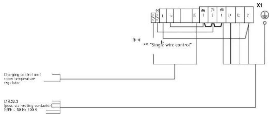
2.5.2 Electrical Connection
The heating elements are connected electrically with 3 / N / PE 50Hz400V or in the units WSP 2010 also with 1 / N / PE 50Hz230V .
Direct connection with NYM is possible. The number of supply cables and wires as well as cable cross sections depends on the connection rating of the unit and the type of mains connection and on special electricity supply company regulations. Observe the appropriate circuit diagrams for this.
When connecting the unit to an automatic charging control unit, voltages may occur at the terminals A1/Z1 and A2/Z2 even when the fuses are removed.
Connection
Relieve the strain on the electrical connecting leads as required and connect according to the electrical circuit diagram in the device (on the inside of the right side panel) or the connection diagram.
If the bracket in the switching area for holding the mains terminals is poorly accessible due to too small a spacing, it can be swung forward during connection work after loosening the screw (not removing) in the rear panel.
A bridged must be inserted between "N" and "A2/Z2" for operation with "single-wire control"*!
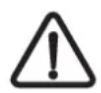
Power adaptation according to rated charging time
By moving or removing bridges at the terminals, the output can be adapted to the rated charging time specified by the electricity supply company.
| Heating element model | 8h (series) | 6h (heating element fitting set) | ||||
| Rated charging time | 8h | 9h | 10h | 5h | 6h | 7h |
| Connection variants (kW) Model | ① | ② | ③ | ① | ② | ③ |
| WSP 2010 | 2.0 | 1.83 | 1.67 | 2.7 | 2.47 | 2.25 |
| WSP 3010 | 3.0 | 2.75 | 2.5 | 4.1 | 3.76 | 3.42 |
| WSP 4010 | 4.0 | 3.66 | 3.33 | 5.5 | 5.04 | 4.58 |
| WSP 5010 | 5.0 | 4.58 | 4.16 | 6.5 | 5.96 | 5.42 |
| WSP 6010 | 6.0 | 5.5 | 5.0 | 8.1 | 7.42 | 6.75 |
| WSP 7010 | 7.0 | 6.42 | 5.83 | 9.0 | 8.24 | 7.5 |
(1)
②
③
Unit rating plate
Observe the labelling on the rating plate and the circuit diagram!
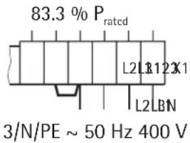
After connecting electrically, the box corresponding to the connection rating and rated charging time of the unit on the rating plate and the circuit diagram in these installation instructions should be marked with a smear-proof ballpoint pen.
2.5.3 Unit Ready for Operation
Cleaning the unit (fig. 13 and 14)
The open unit must be cleaned after installation and insertion of the storage blocks.
The fans and the air guidance assembly must be removed for this.
- Unscrew and remove the air guidance assembly (16)
- Lift and remove the fan (18) after loosening (not removing) the screws at the front of the support brackets (pay attention to cable laying!).
In some units, the discharge temperature control unit (19) including support plate must be unscrewed.
Make sure the wires are not damaged when setting down the removed parts.
- Clean the floor plate and fan (avoid damage to lamellas!). Then re-install the fans, possibly the temperature limiter and the air guidance module (correct cable laying!).
Close the unit (fig. 15 and 16)
- Hang in the inside front wall with thermal insulation swung forward slightly at an angle at the top edge and screw at the bottom edge with 2 screws;
- Hang in the right side wall at the bottom, tilt up, hang in at top and fix with screw; (reverse order see 2.5.1 - disassembly right side wall fig. 6)
- Hang in front wall at top, swing to the heater at the bottom and fix with 2 screws (always use the two inside threaded holes) (fig. 15);
- Screw on the air outlet grille, screwing the screws hand tight and then back about 1 turn (fig. 16);
- Place the air inlet grille at an angle on the lugs in the heater base, swing round at the top and snap in behind the air outlet grille (fig. 16).
Connection diagram . . .
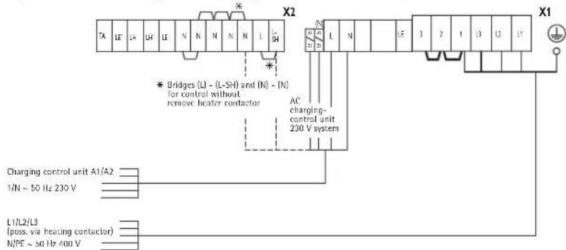
... for integrated room temperature regulators RTi 100 M/RTi 101 EP
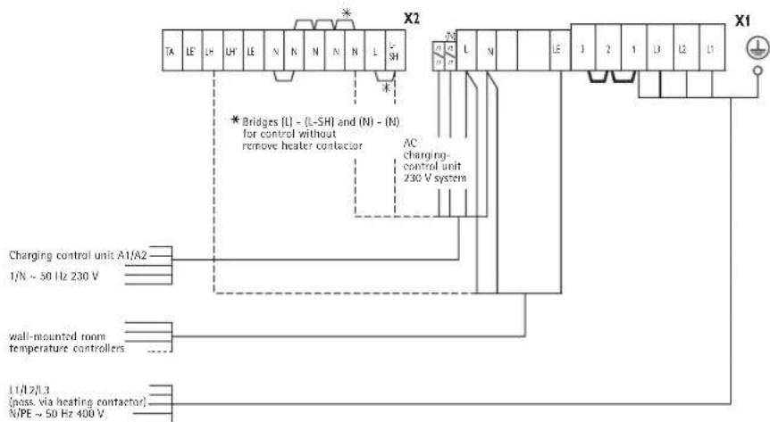
... for wall-mounted room temperature regulators
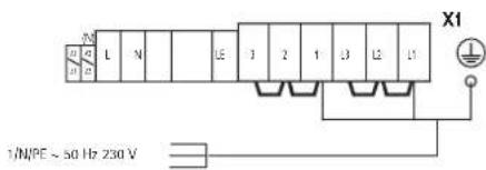
... for single-phase connection (max. 2 kW)
... for storage heater replacement "old-new" with wall-mounted room temperature regulator and missing daytime electricity supply
2.6 First-time Operation
2.6.1 Function Test
Check the function of the fan for the storage unit by switching on the room temperature regulator.
2.6.2 Charging
The units can be started without initial heating up after the function test. Charging takes place either manually with the adjuster of the mechanical charging control unit or automatically with the available Elfamatic charging control unit.
During initial charging, the charging in kWh must be determined and compared with the maximum permissible charging from the cold state specified in the "Technical Data". The determined charging may not exceed the maximum permissible charging from the cold state.

During initial charging, a smell may be produced, the room should therefore be adequately aired (1.5 times air change, e.g. tilted windows). Initial charging in the bedroom should not take place when sleeping in it if possible.
2.7 Repair, Conversion of Unit
Proceed according to these installation instructions as for the initial installation for re-installation of a unit which has been dismantled for repairs or which was in operation somewhere else.
In these cases the following must be paid special attention: Parts of the thermal insulation at which there are visible signs or damage or change which could impair the safety must be replaced by new parts. The insulation must be tested and the rated consumption measured before commissioning.
2.7.1 Conversion of the Unit
The instructions enclosed with the respective fitting set are applicable for conversions, additions and installations.
2.8 Transfer
Explain the functions of the unit to the user. Draw his attention to the safety instructions in particular.
Hand over the operating and installation instructions to the user.
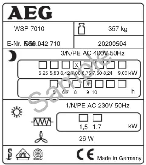
Symbols of the rating plate (Example WSP 7010)
Total weight
Charging
Discharging
Supplementary heater
Fan
Circuit diagram WSP 2010 - 7010
E1 - E6: Heating element (storage heater)
E7: Heating resistor
F1: Safety temperature limiter
M1-M3:Fan
N1: Temperature limiter - charging
N5: Temperature limiter - fan drawer
N4: Temperature limiter - charging
X1: Mains terminal
X2: Terminal
Integr. room temperature regulator
E9: Heating resistor
N6: Temperature regulator - discharging
S2: Rocker switch - discharging
Z1: Radio interference suppressor
Supplementary heater
E8: Supplementary heating element
N2: Temperature regulator - supplementary heater
N3: Temperature regulator - supplementary heater
S1: Rocker switch - supplementary heater
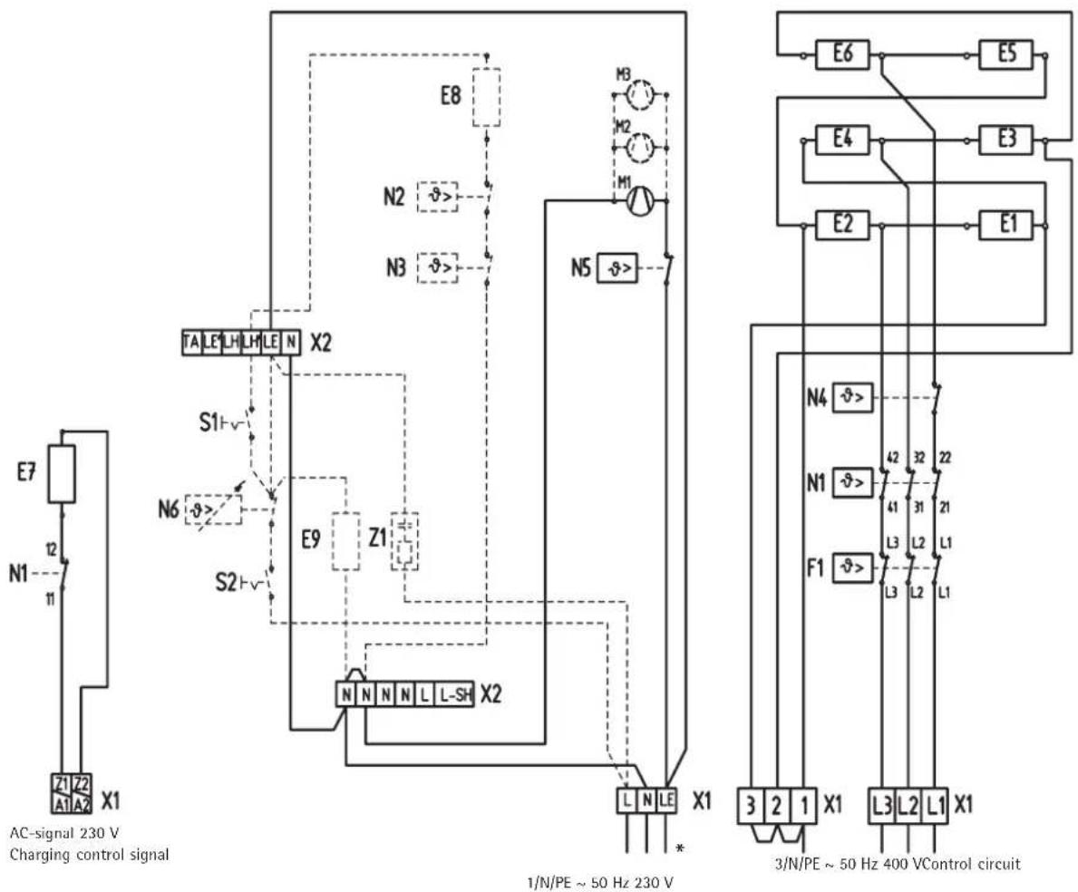
* when external RT is connected
Series circuit
Only for WSP 2010
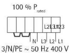
Caution! On a 3/PE AC 50 Hz 230 V mains
Rewiring of the storage heater load circuit necessary!
Circuit diagram for 3/PE AC 50Hz 230 V
Rewiring necessary in the storage heater!
xxx pull off vi wire from E2 and plug to E6
xx pull off br wire from E6 and plug to E4
x pull off ws wire from E4 and plug to E2
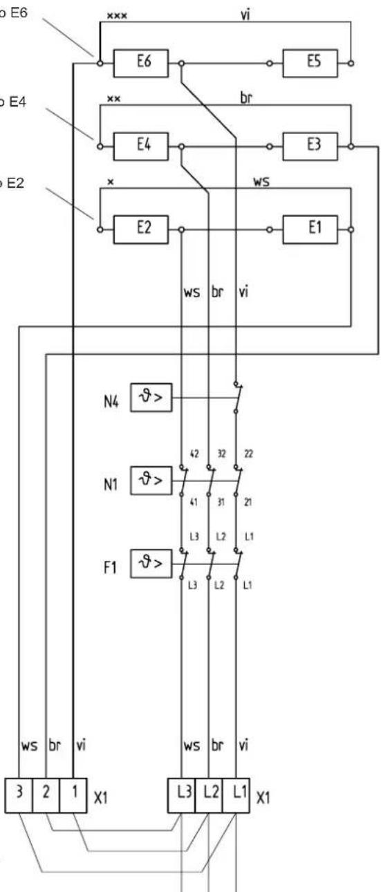
3/PE AC 50 Hz 230V
E1 - E6: (storage) heater
F1: protective temperature limiter
N1: temperature limiter - charging
N4: temperature limiter - charging
X1: mains terminal
Jumper must be wired by customer on site.
3. Environment and recycling
Please help us to protect the environment by disposing of the packaging in accordance with the national regulations for waste processing.
Guarantee
For guarantee please refer to the respective terms and conditions of supply for your country.
The installation, electrical connection and first operation of this appliance should be carried out by a qualified installer.
The company does not accept liability for failure of any goods supplied which are not installed in accordance with the manufacturer's instructions.


- Operating instructions
- Installation Instructions
- Nederlandss
- Inhoudsopgave
- Technical Description
- Operation
- Heat Storage
- Heat Discharge
- Safety Instructions
- Care and Maintenance
- Cleaning the Fluff Screen (fig. 3)
- Important Note
- Technical Data
- Technical Description (page 3, fig. 1)
- Function Principle
- Reducing the Output
- Rules and Regulations
- Installation Site
- Unit Installation (fig. 3-14)
- Unit Installation (fig. 3-6)
- Insert the storage blocks (fig. 10 and 11)
- Electrical Connection
- Connection
- Power adaptation according to rated charging time
- Unit rating plate
- Observe the labelling on the rating plate and the circuit diagram!
- Unit Ready for Operation
- Close the unit (fig. 15 and 16)
- First-time Operation
- Function Test
- Charging
- Repair, Conversion of Unit
- Conversion of the Unit
- Transfer
- Symbols of the rating plate (Example WSP 7010)
- Circuit diagram WSP 2010 - 7010
- Caution! On a 3/PE AC 50 Hz 230 V mains
- Circuit diagram for 3/PE AC 50Hz 230 V
- Environment and recycling
- Guarantee
Brand : AEG
Model : WSP 2010
Category : Heating