C2 - Mixer NUMARK - Free user manual and instructions
Find the device manual for free C2 NUMARK in PDF.
Frequently Asked Questions - C2 NUMARK
User questions about C2 NUMARK
0 question about this device. Answer the ones you know or ask your own.
Ask a new question about this device
Download the instructions for your Mixer in PDF format for free! Find your manual C2 - NUMARK and take your electronic device back in hand. On this page are published all the documents necessary for the use of your device. C2 by NUMARK.
USER MANUAL C2 NUMARK
Welcome to the C2 – a professional 19", 4-channel mixer. Here are some of the features that you will come to love about this device:
■ 8 line, 3 phono, & 2 mic inputs
■ Fader-start crossfader with front panel controls
- Split/blend cue options
- Panning on master fader with stereo/mono switch
■ 5-band ±6/±12dB EQ with rear panel defeat
■ Master balanced XLR outputs with stereo/mono controls
- Cues on each channel with cue/send rear output for sampling and booth cue monitor
■ Channel gain control with PFL meter
- Neutrik™ "Combo" connector (1/4" or XLR plug) for DJ mic
■ Auto-talkover mic input with bass and treble
■ Tape out for direct recording
- Front panel BNC light connector
- Zone output
We hope that the C2 serves you well for many years to come.
Sincerely,
The People of Numark
BOX CONTENTS
C2
■ IEC Power Cable
- Quickstart Guide
■ Safety & Warranty Information Booklet
REGISTRATION
Please go to http://www.numark.com to register your C2. Registering your product ensures that we can keep you up-to-date with any last-minute product developments and provide you with world-class technical support, should you run into any problems.
GROUND RULES
- Make sure all items listed in the BOX CONTENTS section are included in the box.
- READ SAFETY & WARRANTY INFORMATION BOOKLET BEFORE USING THE PRODUCT.
- Study the connection diagram in this guide.
- Place mixer in an appropriate position for operation.
- Make sure all devices are turned off and all faders and gain knobs are set to "zero."
- Connect all stereo input sources as indicated in the diagram.
- Connect the stereo outputs to power amplifier(s), tape decks, and/or other audio sources.
- Plug all devices into AC power.
- Switch everything on in the following order:
• Audio input sources (i.e. turntables, CD players, etc.)
- Mixer
• Last, any amplifiers or output devices
-
When turning off, always reverse this operation by turning off:
-
Amplifiers
- Mixer
- Last, any input devices
CONNECTION DIAGRAM
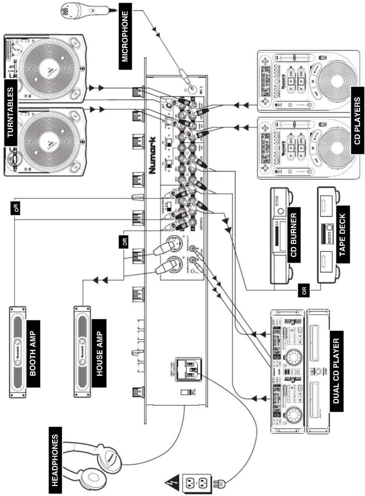
flowchart
graph TD
    A["HEADPHONES"] --> B["BOOTH AMP"]
    A --> C["HOUSE AMP"]
    B --> D["Numark"]
    C --> D
    D --> E["Turntables"]
    E --> F["MICROPHONE"]
    G["DUAL CD PLAYER"] --> H["CD BURNER"]
    G --> I["TAPE DECK"]
    H --> J["CD PLAYERS"]
    I --> J
    K["OR"] --> L["OUTPUTS"]
    M["OR"] --> N["OUTPUTS"]
    O["OR"] --> P["OUTPUTS"]
    Q["OR"] --> R["OUTPUTS"]
    S["OR"] --> T["OUTPUTS"]
    U["OR"] --> V["OUTPUTS"]
    W["OR"] --> X["OUTPUTS"]
    Y["OR"] --> Z["OUTPUTS"]
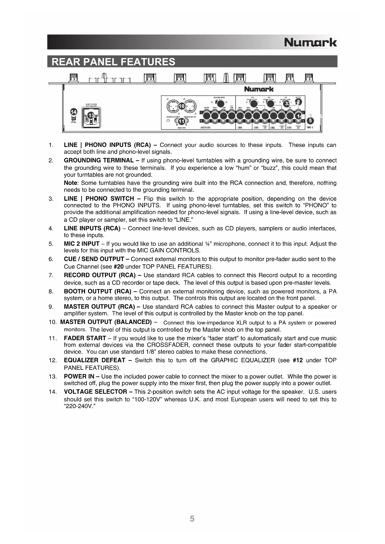
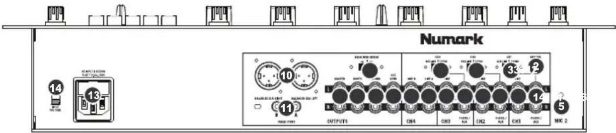
REAR PANEL FEATURES
text_image
Numark 14 13 10 11 OUTPUTS CH4 CH9 CH2 CH1 MAC 2 5 MAY 18 33 14 NAMOS 0.5 Litter NAMOS 0.5 Litter NAMOS 0.5 Litter NAMOS 0.5 Litter NAMOS 0.5 Litter NAMOS 0.5 Litter NAMOS 0.5 Litter NAMOS 0.5 Litter NAMOS 0.5 Litter NAMOS 0.5 Litter NAMOS 0.5 Liter NAMOS 0.5 Liter NAMOS 0.5 Liter NAMOS 0.5 Liter NAMOS 0.5 Liter NAMOS 0.5 Liter NAMOS 0.5 Liter NAMOS 0.5 Liter NAMOS 0.5 Liter NAMOS 0.5 Liter NAMOS 0.5 Litter NAMOS 0.5 Litter NAMOS 0.5 Litter NAMOS 0.5 Litter NAMOS 0.5 Litter NAMOS 0.5 Litter NAMOS 0.5 Litter NAMOS 0.5 Litter NAMOS 0.5 Litter NAMOS 0.5 Linner NAMOS 0.5 Linner NAMOS 0.5 Linner NAMOS 0.5 Linner NAMOS 0.5 Linner NAMOS 0.5 Linner NAMOS 0.5 Linner NAMOS 0.5 Linner NAMOS 0.5 Linner NAMOS 0.5 Linner NAMOS 0.5 LInner NAMOS 0.5 LInner NAMOS 0.5 LInner NAMOS 0.5 LInner NAMOS 0.5 LInner NAMOS 0.5 LInner NAMOS 0.5 LInner NAMOS 0.5 LInner NAMOS 0.5 LInner NAMOS 0.5 LInner NAMOS 0.5 LOuter NAMOS 0.5 Outer NAMOS 0.5 Outer NAMOS 0.5 Outer NAMOS 0.5 Outer NAMOS 0.5 Outer NAMOS 0.5 Outer NAMOS 0.5 Outer NAMOS 0.5 Outer NAMOS 0.5 Outer NAMOS 0.5 Outer NAMOS 0.5 Outer- LINE | PHONO INPUTS (RCA) – Connect your audio sources to these inputs. These inputs can accept both line and phono-level signals.
- GROUNDING TERMINAL – If using phono-level turntables with a grounding wire, be sure to connect the grounding wire to these terminals. If you experience a low "hum" or "buzz", this could mean that your turntables are not grounded.
Note: Some turntables have the grounding wire built into the RCA connection and, therefore, nothing needs to be connected to the grounding terminal. - LINE | PHONO SWITCH – Flip this switch to the appropriate position, depending on the device connected to the PHONO INPUTS. If using phono-level turntables, set this switch to "PHONO" to provide the additional amplification needed for phono-level signals. If using a line-level device, such as a CD player or sampler, set this switch to "LINE."
- LINE INPUTS (RCA) – Connect line-level devices, such as CD players, samplers or audio interfaces, to these inputs.
- MIC 2 INPUT – If you would like to use an additional 14 " microphone, connect it to this input. Adjust the levels for this input with the MIC GAIN CONTROLS.
- CUE / SEND OUTPUT – Connect external monitors to this output to monitor pre-fader audio sent to the Cue Channel (see #20 under TOP PANEL FEATURES).
- RECORD OUTPUT (RCA) – Use standard RCA cables to connect this Record output to a recording device, such as a CD recorder or tape deck. The level of this output is based upon pre-master levels.
- BOOTH OUTPUT (RCA) – Connect an external monitoring device, such as powered monitors, a PA system, or a home stereo, to this output. The controls this output are located on the front panel.
- MASTER OUTPUT (RCA) – Use standard RCA cables to connect this Master output to a speaker or amplifier system. The level of this output is controlled by the Master knob on the top panel.
- MASTER OUTPUT (BALANCED) – Connect this low-impedance XLR output to a PA system or powered monitors. The level of this output is controlled by the Master knob on the top panel.
- FADER START – If you would like to use the mixer's "fader start" to automatically start and cue music from external devices via the CROSSFADER, connect these outputs to your fader start-compatible device. You can use standard 1/8" stereo cables to make these connections.
- EQUALIZER DEFEAT - Switch this to turn off the GRAPHIC EQUALIZER (see #12 under TOP PANEL FEATURES).
- POWER IN – Use the included power cable to connect the mixer to a power outlet. While the power is switched off, plug the power supply into the mixer first, then plug the power supply into a power outlet.
- VOLTAGE SELECTOR – This 2-position switch sets the AC input voltage for the speaker. U.S. users should set this switch to "100-120V" whereas U.K. and most European users will need to set this to "220-240V."
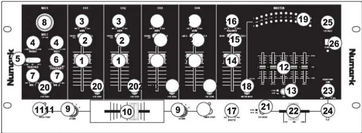
TOP PANEL FEATURES
text_image
M15 8 4 5 7 20 CH1 3 4 6 7 20 CH2 3 1 2 1 20 CH3 3 2 1 20 CH4 16 15 14 18 MASTER 19 25 26 12 13 23 17 21 22 24 11 11 9 10 9 17 22 24 MOSI START ATTON ATTON ATTON ATTON ATTON ATTON ATTON ATTON ATTON ATTON ATTON ATTON ATTON ATTON ATTON ATTON ATTON ATTON ATTON ATTON ATTON ATTON ATTON ATTON ATTON ATTON ATTON ATTON ATTON ATTON ATTON ATTON ATTON ATTON ATTON ATTON ATTON ATTON ATTON ATTON ATTON ATTON ATTON ATTON ATTON ATTON ATTON ATTON ATTON ATTON ATON ATTON ATTON ATTON ATTON ATTON ATTON ATTON ATTON ATTON ATTON ATTON ATTON ATTON ATTON ATTON ATTON ATTON ATTON ATTON ATTON ATTON ATTON ATTON ATTON ATTON ATTON ATTON ATTON ATTON ATTON ATTON ATTON ATTON ATTON ATTON ATTON ATTON ATTON ATTON ATTON ATTON ATTON ATTON ATTON ATTON ATTON ATTON ATTON ATTON ATRAT ATRAT ATRAT ATRAT ATRAT ATRAT ATRAT ATRAT ATRAT ATRAT ATRAT ATRAT ATRAT ATRAT ATRAT ATRAT ATRAT ATRAT ATRAT ATRAT ATRAT ATRAT ATRAT ATRAT ATRAT ATRAT ATRAT ATRAT ATRAT ATRAT ATRAT ATRAT ATRAT ATRAT BRTA BRTA BRTA BRTA BRTA BRTA BRTA BRTA BRTA BRTA BRTA BRTA BRTA BRTA BRTA BRTA BRTA BRTA BRTA BRTA BRTA BRTA BRTA BRTA BRTA BRTA BRTA BRTA BRTA BRTA BRTA BRTA BRTA BRTA CNTB CNTB CNTB CNTB CNTB CNTB CNTB CNTB CNTB CNTB CNTB CNTB CNTB CNTB CNTB CNTB CNTB CNTB CNTB CNTB CNTB CNTB CNTB CNTB CNTB CNTB CNTB CNTB CNTB CNTB CNTB CNTB CNTB CNTB NUTR NUTR NUTR NUTR NUTR NUTR NUTR NUTR NUTR NUTR NUTR NUTR NUTR NUTR NUTR NUTR NUTR NUTR NUTR NUTR NUTR NUTR NUTR NUTR NUTR NUTR NUTR NUTR NUTR NUTR NUTR NUTR NUTR NUTR OCTO ECTO ECTO ECTO ECTO ECTO ECTO ECTO ECTO ECTO ECTO ECTO ECTO ECTO ECTO ECTO ECTO ECTO ECTO ECTO ECTO ECTO ECTO ECTO ECTO ECTO ECTO ECTO ECTO ECTO ECTO ECTO ECTO ECTO EACT OCTO ECTO ECTO ECTO ECTO ECTO ECTO ECTO ECTO ECTO ECTO ECTO ECTO ECTO ECTO ECTO ECTO ECTO ECTO ECTO ECTO ECTO ECTO ECTO ECTO ECTO ECTO ECTO ECTO ECTO ECTO ECTO ECTO SINT OCTO SINT OCTO SINT OCTO SINT OCTO SINT OCTO SINT OCTO SINT OCTO SINT OCTO SINT OCTO SINT OCTO SINT OCTO SINT OCTO SINT OCTO SINT OCTO SINT OCTO SINT OCTO SINT OCTO SINT OCTO SINT OCTO SINT OCTO SINT SINT OCTS SINT OCTS SINT OCTS SINT OCTS SINT OCTS SINT OCTS SINT OCTS SINT OCTS SINT OCTS SINT OCTS SINT OCTS SINT OCTS SINT OCTS SINT OCTS SINT OCTS SINT OCTS SINT OCTS SINT OCTS SINT OCTS SINT OCTS SINT OCT SINT OCT SINT OCT SINT OCT SINT OCT SINT OCT SINT OCT SINT OCT SINT OCT SINT OCT SINT OCT SINT OCT SINT OCT SINT OCT SINT OCT SINT OCT SINT OCT SINT OCT SINT OCT SINT OCT SINT OCT SINT OCT SINT OCT SINT OCT SINT OCT SINT OCF TIN RIN RIN RIN RIN RIN RIN RIN RIN RIN RIN RIN RIN RIN RIN RIN RIN RIN RIN RIN RIN RIN RIN RIN RIN RIN RIN RIN RIN RIN RIN RIN RIN RIN RIN RIN RIN RIN RIN RIN RIN RIN RIN RIN RIN RIN RIN RIN RIN RIN RIN LUN TIN TIN TIN TIN TIN TIN TIN TIN TIN TIN TIN TIN TIN TIN TIN TIN TIN TIN TIN TIN TIN TIN TIN TIN TIN TIN TIN TIN TIN TIN TIN TIN TIN TIN TIN TIN TIN TIN TIN TIN TIN TIN TIN TIN TIN TIN TIN TIN TIN TIN TAIN TAIN TAIN TAIN TAIN TAIN TAIN TAIN TAIN TAIN TAIN TAIN TAIN TAIN TAIN TAIN TAIN TAIN TAIN TAIN TAIN TAIN TAIN TAIN TAIN TAIN TAIN TAIN TAIN TAIN TAIN TAIN TAIN TAIN TAIN TAIN TAIN TAIN TAIN TAIN TAIN TAIN TAIN TAIN TAIN TAIN UEN UEN UEN UEN UEN UEN UEN UEN UEN UEN UEN UEN UEN UEN UEN UEN UEN UEN UEN UEN UEN UEN UEN UEN UEN UEN UEN UEN UEN UEN UEN UEN UEN UEN UEN UEN UEN UEN UEN UEN UEN UEN UEN UEN UEN UEN UEN UEN UEN UEN UAN UAN UAN UAN UAN UAN UAN UAN UAN UAN UAN UAN UAN UAN UAN UAN UAN UAN UAN UAN UAN UAN UAN UAN UAN UAN UAN UAN UAN UAN UAN UAN UAN UAN UAN UAN UAN UAN UAN UAN UAN UAN UAN UAN UAN UAN UAN UAN UAN UAN UAM DENTU VENTU VENTU VENTU VENTU VENTU VENTU VENTU VENTU VENTU VENTU VENTU VENTU VENTU VENTU VENTU VENTU VENTU VENTU VENTU VENTU VENTU VENTU VENTU VENTU VENTU VENTU VENTU VENTU VENTU VENTU VENTU VENTU VENTU VANT DENTU VENTU VENTU VENTU VENTU VENTU VENTU VENTU VENTU VENTU VENTU VENTU VENTU VENTU VENTU VENTU VENTU VENTU VENTU VENTU VENTU VENTU VENTU VENTU VENTU VENTU VENTU VENTU VENTU VENTU VENTU VENTU VENTU GNT DENTU GNT DENTU GNT DENTU GNT DENTU GNT DENTU GNT DENTU GNT DENTU GNT DENTU GNT DENTU GNT DENTU GNT DENTU GNT DENTU GNT DENTU GNT DENTU GNT DENTU GNT DENTU GNT DENTU GNT DENTU GNT DENTU GNT DENTU GNT GNT DENTU GNT DENTU GNT DENTU GNT DENTU GNT DENTU GNT DENTU GNT DENTU GNT DANT DANT DANT DANT DANT DANT DANT DANT DANT DANT DANT DANT DANT DANT DANT DANT DANT DANT DANT DANT DANT DANT DANT DANT DANT DANT DANT DANT DANT DANT DANT DANT DANT DANT DANT DANT DANT DANT DANT DANT DANT DANT DANT DANT DANT DANT DANT DANT DANT DANT DART DANT DANT DANT DANT DANT DANT DANT DANT DANT DANT DANT DANT DANT DANT DANT DANT DANT DANT DANT DANT DANT DANT DANT DANT DANT DANT DANT DANT DANT DANT DANT DANT DANT DANT DANT DANT DANT DANT DANT DANT DANT DANT DANT DANT DANT DANT DANT DANT DANT DAntD ANGOT INN INN INN INN INN INN INN INN INN INN INN INN INN INN INN INN INN INN INN INN INN INN INN INN INN INN INN INN INN INN INN INN INN INN INN INN INN INN INN INN INN INN INN INN INN INN INN INN INN INN INn IIT IIT IIT IIT IIT IIT IIT IIT IIT IIT IIT IIT IIT IIT IIT IIT IIT IIT IIT IIT IIT IIT IIT IIT IIT IIT IIT IIT IIT IIT IIT IIT IIT IIT IIT IIT IIT IIT IIT IIT IIT IIT IIT IIT IIT IIT IIT IIT IIT IIT ITT IIT IIT IIT IIT IIT IIT IIT IIT IIT IIT IIT IIT IIT IIT IIT IIT IIT IIT IIT IIT IIT IIT IIT IIT IIT IIT IIT IIT IIT IIT IIT IIT IIT IIT IIT IIT IIT IIT IIT IIT IIT IIT IIT IIT IIT IIT IIT IIT IIT IGT II IT II IT II IT II IT II IT II IT II IT II IT II IT II IT II IT II IT II IT II IT II IT II IT II IT II IT II IT II IT II IT II IT II IT II IT II IT II IT II IT II IT II IT II IT II IT II IT II IT II IT II IT II IT II IT II IT II IT II IT II IT II IT II IT II IT II IT II IT II IT II IT II IT II IT II IS III III III III III III III III III III III III III III III III III III III III III III III III III III III III III III III III III III III III III III III III III III III III III III III III III III III III III III III III III III III III III III III III III III III III III III III III III III III III III III III III III III III III III III III III III III III III III III III III III III III IIIIII III III III III III III III III III III III III III III III III III III III III III III III III III III III III III III III III III III III III III III III IIIIII IV TH IV TH IV TH IV TH IV TH IV TH IV TH IV TH IV TH IV TH IV TH IV TH IV TH IV TH IV TH IV TH IV TH IV TH IV TH IV TH IV TH IV TH IV TH IV TH IV TH IV TH IV TH IV TH IV TH IV TH IV TH IV TH IV TH IV TH IV TH IV TH IV TH IV TH IV TH IV TH IV TH IV TH IV TH IV TH IV TH IV TH IV TH IV TH IV TH IV TH IVTH IV TH IV TH IV TH IV TH IV TH IV TH IV TH IV TH IV TH IV TH IV TH IV TH IV TH IV TH IV TH IV TH IV TH IV TH IV TH IV TH IV TH IV TH IV TH IV TH IV TH IV TH IV TH IV TH IV TH IV TH IV TH IV TH IV TH IV TH IV TH IV TH IV TH IV TH IV TH IV TH IV TH IV TH IV TH IV TH IV TH IV TH IV TH IV TH IV TH IVINPUT CONTROLS
- CHANNEL FADER – Adjusts the audio level of the corresponding channel.
- INPUT SELECTOR – Selects the input source to be routed to the corresponding channel. Input jacks are located on the rear panel.
- CHANNEL GAIN – Adjusts the channel's pre-fader and pre-EQ gain level.
MICROPHONE CONTROLS
- MIC TREBLE & BASS – Adjusts the treble (high) and bass (low) frequencies of the audio for both mic inputs.
Tip: If you experience feedback when using a microphone at loud levels, try turning down the high (treble) frequencies. - TALKOVER SWITCH – Toggles between three “talkover” settings, allowing you to speak over the music. (Talkover only applies to MIC 1. MIC 2’s level can only be controlled by its MIC GAIN knob.)
- -12dB – Reduces the combined levels of Channels 1-4 to -12dB (an appropriate “talkover” level).
- ON – Leaves Channels 1-4 at the levels you designated while the mic remains on.
- AUTO – Automatically reduces the combined levels of Channels 1-4 to -12dB whenever you talk into the DJ MIC.
- TALKOVER SENSITIVITY – Adjusts the volume threshold at which auto-talkover activates. The higher the sensitivity, the quieter you need to speak into the mic to activate auto-talkover.
- MIC GAIN - Adjusts the audio level of the microphone signal. The MIC 1 knob controls the volume of DJ mic input. The MIC 2 knob controls the volume of the MIC 2 input.
- MIC 1 INPUT - Connect a microphone to this input with an XLR or 14 cable.
CROSSFADER CONTROLS
-
CROSSFADER ASSIGN - Selects which input channel will be heard when the crossfader is moved towards this knob. All channels not assigned will remain active.
-
CROSSFADER - Blends audio between the channels assigned to the left and right side of the crossfader.
Note: The crossfader is user-replaceable if it should ever wear out. Simply remove the facepanel, then remove the screws holding it in position. Replace the fader with a quality authorized replacement from your local Numark retailer only.
- FADER START – Enables or disables "fader start" on the corresponding side of the crossfader. When fader start is enabled on one side, moving the crossfader toward that side will cause any fader start-compatible device (connected to the FADER START output on the rear panel) to start playing.
EQUALIZER
- GRAPHIC EQUALIZER (EQ) – Adjusts the high, mid-range, and low frequencies of the combined audio output from Channels 1-4. EQ compensates for differences in source material sound quality. The center frequencies of this 5-band graphic equalizer are 63Hz, 250Hz, 1kHz, 4kHz and 16kHz. Faders have a center detent for an accurate "flat" response.
Tips:
- Boosting (increasing) the 63Hz band will increase the deep bass tones and "kick drum" sounds, but could cause your amplifiers to "clip" or distort if set too high.
- Slightly cutting (decreasing) the 250Hz and 1kHz bands will give the sound some extra clarity.
- Boosting the 16kHz band will give the audio a sharper tone.
-
As a general rule, the less equalization, the better.
-
EQ ADJUST – Determines how much the equalization changes when you move the EQ faders. When this button is raised, the EQ faders will adjust each band by 12dB. When the button is pressed, the EQ faders will adjust each band by 6dB.
OUTPUT CONTROLS
- MASTER FADER – Adjusts the output volume of the Program mix.
- STEREO / MONO – Adjusts the Program mix for stereo or mono operation.
- BALANCE – Adjusts the balance of right to left audio of the Program mix.
- BOOTH FADER- Adjusts the audio level from the Booth output level. (This can also be used to supply line level audio to a lighting controller or to lights that are sound activated.)
- METER MODE - Determines whether audio from the Program mix or Cue channel is sent to the STEREO LEVEL INDICATOR.
- STEREO LEVEL INDICATOR – Monitors the audio level of the Program mix or Cue channel, depending on the position of the METER MODE button.
CUE CONTROLS
- CUE / SEND – Sends the pre-fader audio Cue channel for monitoring.
- CUE MODE – When pressed, this button sends all audio in the Cue channel to the left side of the headphones and the Program mix to the right side of the headphones. When raised, you may control the balance of the Cue channel and Program mix with the Cue Blend fader.
HEADPHONE CONTROLS
- MIX – Slide this to mix the Cue channel and Program mix in the headphones. When all the way to the left, only channels routed to the Cue channel will be heard. When all the way to the right, only the Program mix will be heard. The CUE MODE button must be set to BLEND for this fader to work (see #21).
- HEADPHONE GAIN – Adjusts the volume level of the headphone output.
- HEADPHONE OUTPUT – Connect your 1/4" headphones to this output for cueing and mix monitoring.
POWER
- 12V LIGHT CONNECTION – You can connect a 12-volt gooseneck lamp here.
- POWER SWITCH – Turns the mixer on and off. Turn on the mixer after all input devices have been connected and before you turn on amplifiers. Turn off amplifiers before you turn off the mixer.
INTRODUCCIÓN
| INPUTS: | Line: | 10kΩ input impedance | ||||
| 85mV | rms | sensitivity (for 1.22V output) | ||||
| Mic: | 10kΩ input impedance unbalanced | |||||
| 2mV | rms | sensitivity | (for | |||
| 6 | 0 | m | V | |||
| Phono: | 47kΩ input impedance | |||||
| 1.5mV | rms | sensitivity @ 1kHz (for 1.22V output) | ||||
| OUTPUTS: Line: 9V rms max | ||||||
| Headphone: | 0.5W | into | 4747kΩ | |||
| Distortion: | < | 0.01% | ||||
| SIGNAL-TO-NOISE RATIO: Line: > 96dB(max output; JIS-A weighted) Mic: > 78dB | ||||||
| Phono: | > 87dB | |||||
| FREQUENCY RESPONSE: Line: 20Hz - 22kHz ±0.5dB | ||||||
| Mic: | 20Hz | - | 20kHz | ±0.5dB | ||
| Phono: | ±1dB@ | 20Hz | (except to | for reduce | cor | |
| GRAPHIC EQUALIZER: | ±12dB | @ | 63Hz | |||
| ±12dB | @ | 250Hz | ||||
| ±12dB | @ | 1kHz | ||||
| ±12dB | @ | 4kHz | ||||
| ±12dB | @ | 16kHz | ||||
| POWER CONSUMPTION: 10W typical | ||||||
| 17W | w/full | headphone | outp | |||
| DIMENSIONS (W x H x D): | 19" x 7" x 4" (480mm x 175mm x 95mm) | |||||
| WEIGHT: | 8 | 7 | I | b | ||
www.numark.com