ASTRO 4CBP LEON - Heating DOVRE - Free user manual and instructions
Find the device manual for free ASTRO 4CBP LEON DOVRE in PDF.
| Product type | Wood stove / fireplace insert |
| Brand | Dovre |
| Model | ASTRO 4CBP LEON (series 2170/2570) |
| Nominal power | 10 kW |
| Fuel | Natural wood, dry (moisture ≤20%), max length 50 cm |
| Chimney connection diameter | 150 mm (internal) |
| Weight | Approximately 160 kg |
| Approximate dimensions (H x W x D) | 870 x 510 x 440 mm (depending on version) |
| Efficiency | 75.9 % |
| CO emissions (at 13% O2) | 0.06 % |
| Dust emissions | 19 mg/Nm³ |
| Minimum required draft | 12 Pa |
| Flue gas mass flow | 10.1 g/s |
| Temperature at stove outlet | 345 °C |
| Main functions | Heating by convection and radiation, double combustion, air-wash system for glass |
| Adjustments | Primary and secondary air registers |
| Maintenance | Glass cleaning with special cleaner, annual chimney sweeping, lubrication of moving parts, seal checks |
| Safety | Hot surfaces (>100°C), minimum distance to combustible materials, room ventilation |
| Spare parts and repairability | Refractory plates (cast iron/vermiculite), glass, sealing cord, ash pan (depending on version) |
| Installation | Connection to a tight chimney flue, possibility of external air connection |
Frequently Asked Questions - ASTRO 4CBP LEON DOVRE
User questions about ASTRO 4CBP LEON DOVRE
0 question about this device. Answer the ones you know or ask your own.
Ask a new question about this device
Download the instructions for your Heating in PDF format for free! Find your manual ASTRO 4CBP LEON - DOVRE and take your electronic device back in hand. On this page are published all the documents necessary for the use of your device. ASTRO 4CBP LEON by DOVRE.
USER MANUAL ASTRO 4CBP LEON DOVRE
natural_image
Exterior view of a modern portable stove with visible flames and wood shavings (no text or symbols)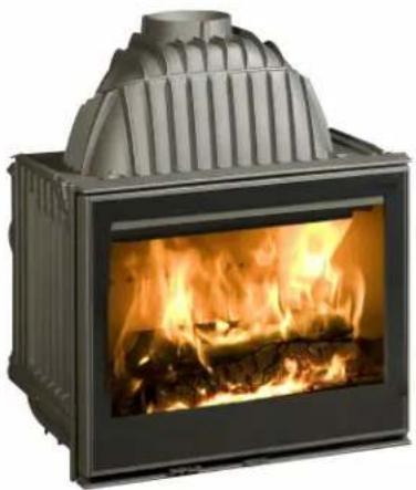
natural_image
Exterior view of a modern office building (no signage)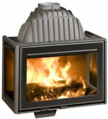
natural_image
Exterior view of a modern portable stove with visible flames and wood inside (no text or symbols)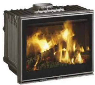
natural_image
Exterior view of a portable stove with visible flames and wood shavings (no text or symbols)
natural_image
Exterior view of a black industrial stove with visible flames and wood shavings (no text or symbols)Inbouwhaard 2175CBS, 2176CBS, 2175CBS3, 2576CBS en 2575CBS3
text_image
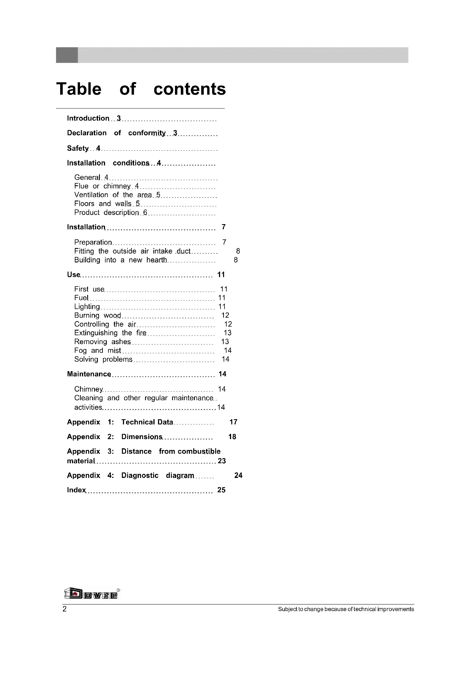
Dovie®Inhoudsopgave
Inleiding 3
natural_image
Technical line drawing of a mechanical device with internal components and a close-up inset showing a tool (no text or symbols present)natural_image
Technical line drawing of a mechanical assembly with internal components and mounting holes (no text or symbols)natural_image
Illustration of layered geological strata with no visible text or symbolsnatural_image
Illustration of a composite material or geological sample with layered textures and a highlighted section (no text or symbols)natural_image
Illustration of fragmented, irregularly shaped objects with no visible text or symbolstext_image
Technical diagram of a mechanical device with labeled components A, B, and C, showing internal structure and mounting points.natural_image
Technical line drawing of a mechanical assembly with no visible text or symbolsnatural_image
Technical diagram of a vehicle's internal structure with no visible text or symbolsnatural_image
Technical line drawing of a mechanical assembly with internal components and an arrow indicating motion (no text or symbols)natural_image
Technical line drawing of a mechanical assembly with no visible text or symbols
Declaration of conformity 3.
Safety 4
Installation conditions 4....
General 4
Flue or chimney 4
Ventilation of the area 5
Floors and walls 5
Product description 6
Installation.... 7
Preparation 7
Fitting the outside air intake duct.... 8
Building into a new hearth.... 8
Use.... 11
First use 11
Fuel 11
Lighting 11
Burning wood 12
Controlling the air 12
Extinguishing the fire 13
Removing ashes 13
Fog and mist 14
Solving problems 14
Maintenance.... 14
Chimney 14
Cleaning and other regular maintenance.
activities....14
Appendix 1: Technical Data.... 17
Appendix 2: Dimensions.... 18
Appendix 3: Distance from combustible
material 23
Appendix 4: Diagnostic diagram.... 24
Index 25
Introduction
Dear user,
In buying this DOVRE heating appliance, you have chosen a high quality product. This product is part of a new generation of energy saving and environmentally friendly heating appliances. These appliances make optimal use of convection heat as well as thermal radiation (radiant heat).
▶ Your DOVRE appliance has been manufactured with state-of-the-art production equipment. In the unlikely event of a malfunction, you can always rely on DOVRE for support and service. Hereby
The appliance is not to be modified; always use original parts.
The appliance is intended for use in a living room. It must be connected hermetically to a well-functioning chimney.
We advise you to let an authorized and competent installation company install the appliance.
▶ DOVRE cannot be held liable for any problems or damage resulting from incorrect installation. Weelde 20-05-2008
▶ Observe the following safety rules when installing and using the appliance.
Notified body: 2013
In this manual, you can read how the DOVRE heatingGehem
appliance can be installed, used and maintained safely. Should you require additional information or technical data, or should you experience an installation problem, please contact your supplier first.
text_image
Gehem Jen© 2012 DOVRE NV
Due to continuous product improvement, specifications of the delivered appliance may differ from the content of this booklet without further notice.
DOVRE N.V.
⚠️ Please note: All safety regulations must be complied with strictly.
⚠️ Carefully read the instructions for installation, use and maintenance before you start using the appliance.
The appliance must be installed in accordance with the laws and requirements of your country.
All local regulations and the regulations relating to national and European standards must be observed when installing the appliance.
Read the instructions for installation, use and maintenance supplied with the appliance.
It is preferable to have the appliance installed by an authorized and competent installation company. They will be aware of the applicable regulations and requirements.
The appliance is designed for heating purposes. All surfaces, including the glass and the connecting tube, can get very hot (over 100°C)! For operation, use a so-called "cold hand" or an oven glove.
Don't place any curtains, clothes, laundry or other combustible materials on or near the appliance.
Don't use flammable or explosive substances near the appliance when it is in use.
Avoid a chimney fire by having the chimney swept regularly. Never burn wood with an op door.
In the case of a chimney fire: close all air in of the appliance and alert the fire brigade.
⚠️ If the glass in the appliance is broken or cracked, it must be replaced before you can use the appliance again.
Make sure there is adequate ventilation in the room where the appliance is installed. The combustion will be incomplete in case of insufficient ventilation, which results in toxic gases being produced and spread through the room. See the chapter "Installation requirements" for more information on ventilation.
Installation conditions
General
The appliance must be connected tightly to a well-functioning chimney.
For the connection measurements: see the appendix "Technical data".
Ask the fire brigade and/or your insurance company about any specific requirements and regulations.
Flue or chimney
The flue or chimney is needed for:
▶ Disposing of the combustion gases through natural draught.
The warm air in the flue or chimney is lighter than the outside air so it rises.
The intake of air, needed for the combustion of fuel in the appliance.
A poorly functioning flue or chimney can cause smoke to escape into the room when the door is opened. Damage caused by smoke emissions into the room is not covered by the warranty.
Do not connect multiple appliances (such as a boiler for central heating) to the same flue, unless local or national regulations allow this.
Ask your installer for advice regarding the flue. Refer to the European norm EN13384 for a correct calculation for the flue.
The flue must satisfy the following requirements:
The flue or chimney must be made of fire resistant material, preferably ceramics or stainless steel.
The flue or chimney must be airtight and well cleaned and guarantee sufficient draught.
A draught/vaccuum of 15 - 20 Pa during normal operation is ideal.
Starting from the flue spigot, the flue must run as vertically as possible. Changes in direction and horizontal pieces disrupt the outward flow of combustion gases and may cause the deposit of soot.
The interior measurements should not be too big, to
prevent the combustion gases from cooling down too much, thereby reducing the draught.
The flue or chimney must ideally have the same diameter as the connection collar.
For the nominal diameter: see the appendix "Technical data". If the smoke channel is well insulated, the diameter may be slightly bigger (up to 2x the section of the connection collar).
The section (area) of the smoke channel must be constant. Wider segments and (in particular) narrower segments disrupt the outward flow of combustion gases.
When using a cover plate or exhaust hood: make sure that the cover does not restrict the flue outlet and that the cap does not impede the outward flow of combustion gases.
The chimney must end in a zone that is not affected by surrounding buildings, adjacent trees other obstacles.
The chimney part outside the house must be insulated.
The chimney must be at least 4 metres high.
As a rule of thumb: 60 cm above the ridge of the roof.
If the ridge of the roof is more than 3 metres away from the flue: stick to the measurements in the following figure. A = the highest point of the roof within a distance of 3 metres.
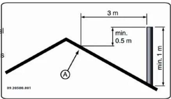
text_image
3 m min. 0.5 m min. 1 m A 09.20500.001Ventilation of the area
For good combustion, the appliance needs air (oxygen). That air is supplied via adjustable air inlets from the area where the appliance is installed.
The combustion will be incomplete in case of insufficient ventilation, which results in toxic gases being produced and spread through the area.
As a rule of thumb, the air supply should be 5.5 cm²/kW. Extra ventilation is needed when:
The appliance is in an area that is well insulated.
There is mechanical ventilation, for example a let central extraction system or an extraction hood in low an open kitchen.
You can provide extra ventilation by having a ventilation louvre installed in the outside wall. or
Make sure that other air consuming appliances (such as tumble-driers, other heating appliances or a bathroom fan) have their own supply of outside air, or are switched off when you use the appliance.
You can also connect the appliance to an outside air supply. A connection kit is supplied for this purpose. This makes additional ventilation unnecessary.
Floors and walls
The floor on which the appliance is placed must have sufficient bearing capacity. For the weight of the appliance, see appendix "Technical data")
There may not be any electrical wires in the floor below the appliance and in the walls

around it.
- Latch

Below the stove, all combustible materials must be removed or protected by at least 6 of concrete and 10 cm of insulation.
- Primary air slide

Combustible walls adjacent to the appliance must be protected with a brick wall of at least 10 cm and 10 cm of insulation.
cm 7. Secondary air slide
-
Outside air connection
-
Side glass (models 2175CBS3 and 2575CBS3 only)

Protect non-combustible walls adjacent to the appliance with at least 2.5 cm of insulation to prevent cracking.
Features

Protect a combustible floor against radiated heat and ash with a fireproof floor plate. See the appendix "Distance from combustible material".
The appliance is supplied with a glove to protect your hand.
The swing direction of the door can be altered. The appliance is supplied with a left-handed door. For a right-handed door a locking rod is needed (sold separately). The instructions for changing the door swing direction are provided with this locking rod.

Ensure that there is sufficient space between the appliance and combustible materials such as furniture.
The appliance is supplied with a connection kit for the outside air supply.

Provide sufficient ventilation around combustible materials such as a mantelpiece. See appendix "Distance from combustible material".
Supplementary feature models 2175 and 2176

A carpet must be kept at a distance of at least 80 cm from the fire.
The models have a connection collar which can take a vertical connection as well as a 45^ connection.

Do not put combustible materials within 50 cm of any convection outlets.
Product description
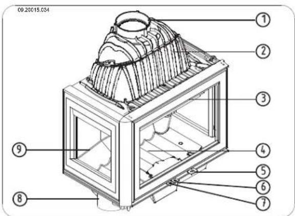
text_image
09.20015.034 ① ② ③ ④ ⑤ ⑥ ⑦ ⑧ ⑨- Connection collar
- Smoke dome
- Door
- Fire compartment

Supplementary feature models 2176 and 2576
These models have a removable ash box.
Supplementary feature models 2175CBS3 and 2575CBS3
The models are supplied as standard in a 3-sided glass design and can be converted to a 2-sided glass design with a glass side on the left or right. You can replace the other side glass with a closed cast-iron side panel. The side panel is sold separately. The instructions for converting the appliance from side glass to cast-iron side panel are supplied with the panel.
Installation
Preparation
▶ Please check the appliance for damage caused during transport or any damage or defects immediately after delivery.

If you detect damage caused during transport or any other damage or defects, do not use appliance and notify the supplier.
Remove the removable parts (fire-resistant inner plates, fire compartment, fire basket, ash removal port and ash pan) from the appliance before you start installing the appliance.

By removing removable parts, it is easier to move the appliance and to avoid damage.

Note the location of those removable parts, that you have no difficulties in installing the parts in the right place later on.
- Remove the inner plate in the middle at the back from the appliance.

Cast iron inner plates protect the combustion chamber and dissipate heat to the environment.
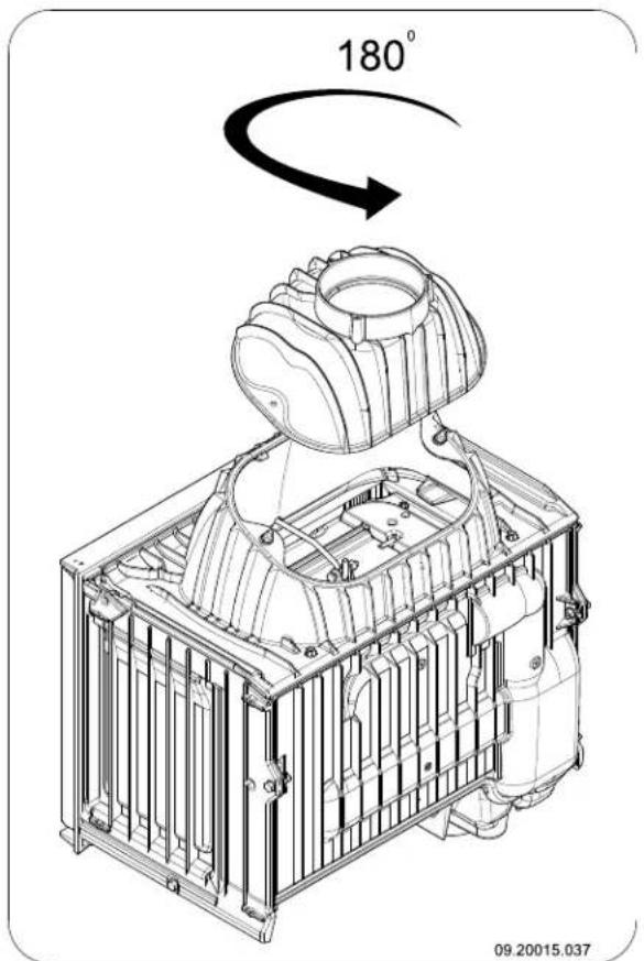
Changing the direction of the connection collar
If you want to use a 45^ connection instead of a vertical connection, for example because it simplifies connection to an existing flue gas duct, you have to rotate the connection collar 180^ ; see the next two figures.
- Loosen the connection between the connection collar and the smoke dome by unscrewing the two M8 nuts.
s2. Lift the connection collar from the two bolts.
- Rotate the connection collar 180° and put the collar back onto the smoke dome.
Removing the fireproof inner
Remove the fireproof inner plates in the correct order according to the instructions below. 5.
- Open the door by turning the latch outward and unlocking the door; see next figure.
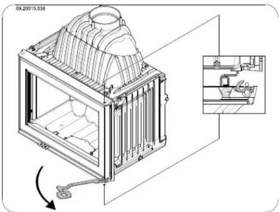
natural_image
Technical line drawing of a mechanical cage assembly with internal components and a close-up inset showing a clamping mechanism (no text or symbols)plates connect the connection collar to the smoke dome by tightening the two M8 nuts.
- Use stove sealant as a seal between the connection collar and the smoke dome.

The stove sealant is not supplied with the appliance.
- First take out the inner plates on both sides of the appliance. In models 2175CBS3 and 2575CBS3 with the side glass, there are no inner plates.
- Remove the left and right inner plates at the back from the appliance.
text_image
180° 09.20015.037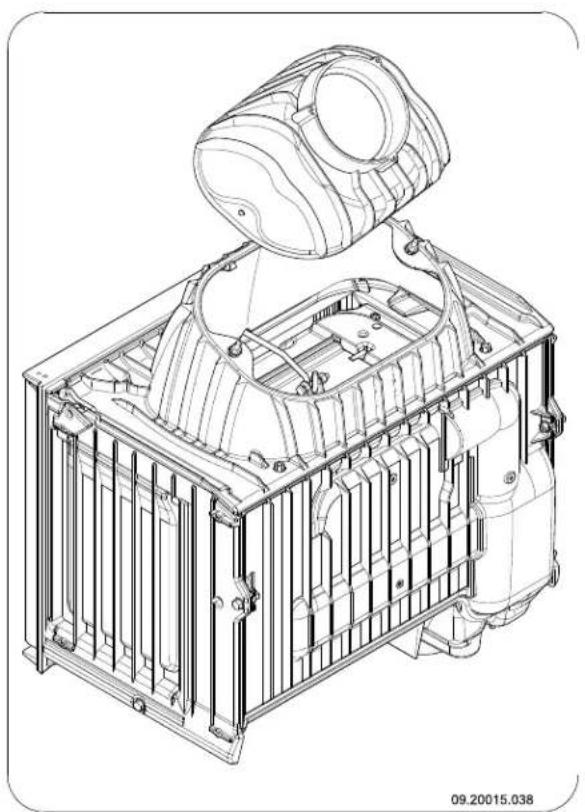
natural_image
Technical line drawing of a mechanical assembly with internal components and mounting brackets (no text or symbols)
Fitting the outside air intake duct
If the appliance is installed in a room without sufficient ventilation, you can install the connecting kit on the appliance for the supply of outside air.
The air supply tube has a diameter of 100 mm. If installing a smooth tube, it may be no longer than 12 m. If accessories such as bends are used, the maximum length (12 m) must be reduced by 1 m for each accessory used.
Outside air intake duct through the wall or the floor and the connection collar
- Make a hole in the wall or the floor (refer to Appendix 2, "Dimensions" for a suitable position of the hole).
- Fit the air intake duct airtight to the wall.
- Fit the connection collar (A) to the M6 stud (B) using the nut (D) and the sealing ring (C); see next figure.
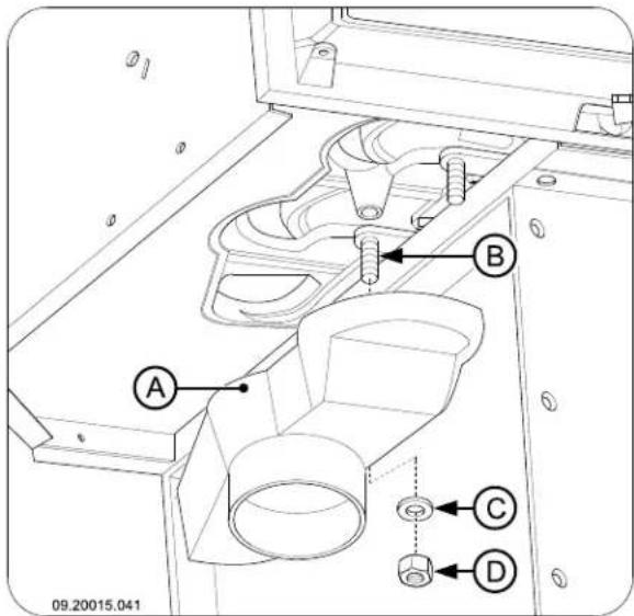
text_image
A B C D 09.20015.041Building into a new hearth
The stove is installed in two stages:
Placing and connecting the stove
▶ Build up the fireplace around the stove.
Placing and connecting the
stove
In the case of new masonry, wait until the masonry has dried sufficiently.
-
Put the appliance at the right height and level it.
-
Check that there is a clearance of 100 mm between the existing walls, which must have the necessary insulation (see chapter "Installation Conditions"), and the back of the appliance; see the next two figures.
-
On the outside air connection: connect the outside air intake to the connection kit you have fitted to the appliance.
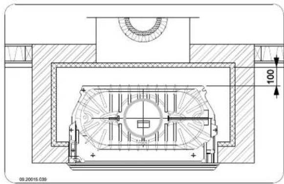
text_image
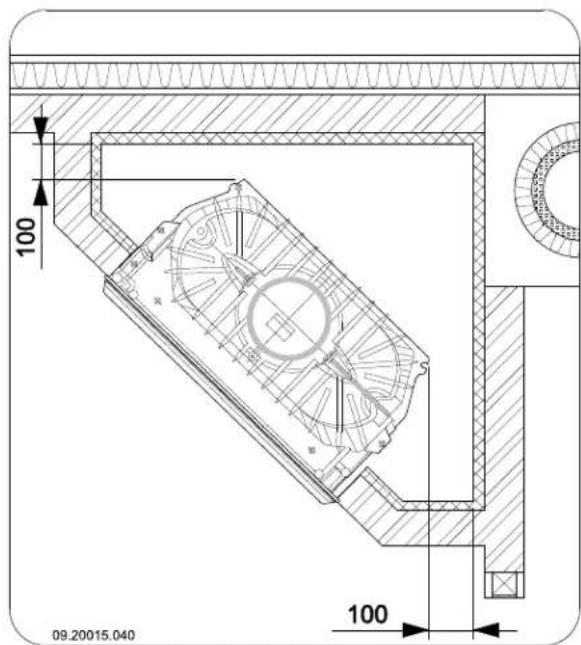
100 09.20015.036Building the fireplace
Inside the fireplace you provide space for convection. In this space the air must be able to move freely. It must be possible for air to be sucked in for combustion, and the air heated by the stove (the convection air) must be able to flow freely into the space to be heated; see next figure.
text_image
100 100 09.20015.040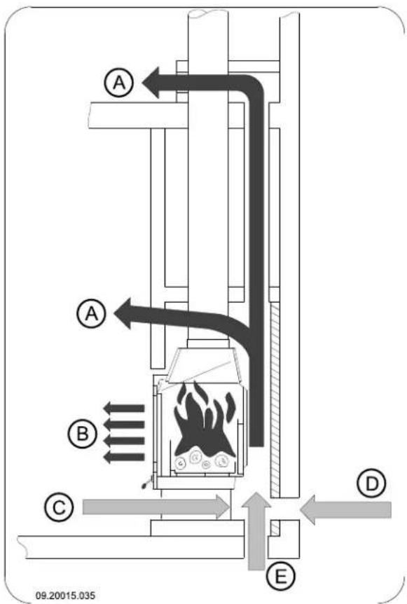
text_image
A A B C D E 09.20015.035- Connect the appliance airtight to the flue (chimney).
A Convection air current
B Radiated heat
- Check the draught in the flue and the seal of the connection on the flue gas duct by making a small intense trial fire with newspaper and dry, small kindling.
Air supply from the room to be heated All, Outside air supply through the wall E Outside air supply through the floor
When building the fireplace, follow these instructions for the convection space:
The top of the convection space must be closed 4. Build the rest of the hearth up to the flue gas hole airtight by means of a closing plate of in the ceiling.
The cover plate must be level and placed at least 30 cm below the flue opening in the ceiling.
Air inlet grates must be fitted at the bottom of the hearth to allow ambient air to flow in. The mining air inlet vent is 250^2cm the space is not
sufficiently ventilated, you must provide for outside air to be allowed in by means of the outside air connection kit or an optional adjustable damper.
Air outlet grates must be fitted at the top of the hearth and just below the cover plate. The minimum air outlet opening is 500 cm

The inlet and outlet grates are available as options.

Do not use combustible material in the convection space, and avoid the effect of thermal bridging when using materials that conduct heat.
Follow the instructions below when building hearth:
- Build the base of the hearth and fit the air inlet grates into the masonry.

You can place the air inlet grates on all sides the base.

Make sure the door of the appliance can swing freely over the hearth floor.
- Build up the hearth up to the smoke dome.

Ensure that a clearance of 2 mm is maintained between the stove and the masonry to accommodate the thermal expansion of the stove.
- The inside of the convection space may, if desired, be cladded with reflective, insulating material.

Additional cladding of the convection space prevents unnecessary thermal radiation
towards outer walls and/or adjacent rooms. It also prevents damage to the insulation in the walls of the hearth.

The masonry may not rest on the stove. Use a support such as a steel beam. Leave a clearance of at least 3 mm between the support and the appliance.
- Put the air outlet grates under the cover plate.
- Make an opening above the cover plate in order to prevent any pressure build-up.
The figure below shows an example of the placing of a stove in a hearth built in accordance with the instructions given above.
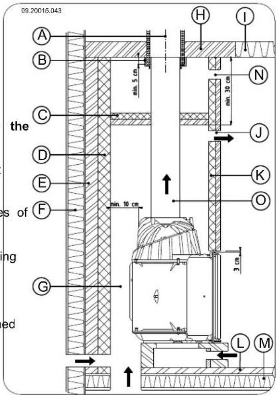
text_image
09.20015.043 A B the C D E F es of ing ed H I N min. 5 cm min. 30 cm J K O min. 10 cm 3 cm G L MA Chimney (flue)
B Gasket
C Cover plate
D Insulation 10 cm
E Fireproof wall min. 10 cm (e.g. cellular concrete)
F Combustible wall
G Convection space
H Fireproof ceiling
I Combustible ceiling
J Convection air outlet
K Insulation
L. Fireproof floor
M Combustible floor
N Opening to prevent pressure build-up
O Connection pipe
Finish
-
Put all dismantled parts back into the appliance in their correct places.
-
Ensure that the newly built hearth is dry enough before firing the stove.

Never light a fire in the appliance without the fireproof inner plates.
The appliance is now ready for use.
Use
First use
When you use the appliance for the first time, make an intense fire and keep it going for a good few hours. This will cure the heat-resistant paint finish. This may result in some smoke and odours. You could open by windows and doors for a while in the area where the appliance is located.
Fuel
This appliance is only suitable for the burning of natural wood; sawn and chopped wood that is sufficiently dry.
Do not use other fuels, as they can lead to serious damage to the appliance.
You are not allowed to use the following fuels, as the pollute the environment and because they heavily soil the appliance and flue, which may lead to a chimney fire:
▶ Treated wood, such as scrap wood, painted wood, impregnated wood, preserved wood, plywood and chipboard.
Plastics, scrap paper and domestic waste.
Wood
Hardwood, such as from oaks, beeches, birches and fruit trees, is the ideal fuel for your stove. This type of wood burns slowly with calm flames. Softwood contains more resins, burns faster and gives off more sparks.
▶ Use dried wood that contains no more than 20% moisture. The wood must have dried for at least 2 years.
Saw the wood to size and split it when it is still in fresh. Fresh wood is easier to split, and split wood dries more easily. Store the wood under a roof where the wind has wind free access.
Do not use damp wood. Damp logs do not produce heat as all of the energy is used in the evaporation of the moisture. This will result in a lot of smoke and soot deposits on the door of the appliance and in the chimney. The water vapour will condense in the appliance and can leak away through chinks in the appliance, causing black stains on the floor. It may also condense in the chimney and form creosote. Creosote is a highly flammable compound and may cause a chimney fire.
Lighting
You can check whether the flue has enough draught by lighting a ball of paper above the baffle plate. A cold flue often does not have enough draught and consequently, some smoke may escape into the room instead of up the chimney. By lighting the fire in the way described here, you can avoid this problem.
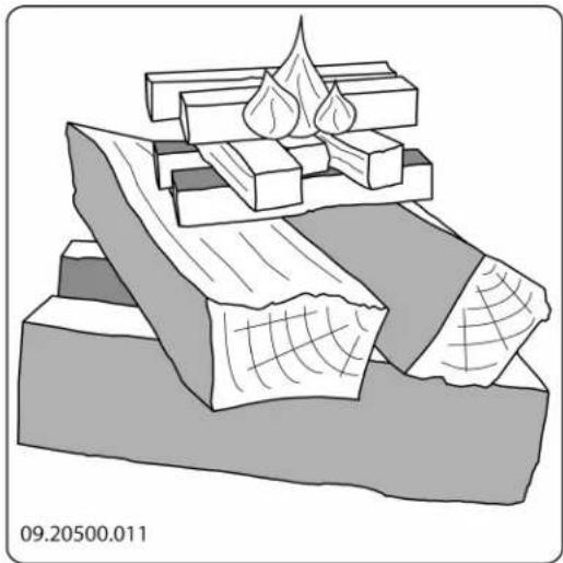
- Stack two layers of medium sized logs crosswise.
- Stack two layers of kindling crosswise on top of the logs.
- Place a firelighter cube in the lower layer of kindling and light the cube according to the instructions on the packaging.
natural_image
Illustration of layered geological strata with no visible text or symbols- Close the door of the appliance and open the primary air inlet and the secondary air inlet of the appliance; see the following figure.
- Let this fire develop into a good blaze until there glowing bed of charcoal. You can then add fuel and adjust the appliance, see the chapter "Stoking with wood".
Burning wood
After you have followed the instructions for lighting:
- Slowly open the door of the appliance.
- Spread out the charcoal bed evenly across the bottom of the fire compartment.
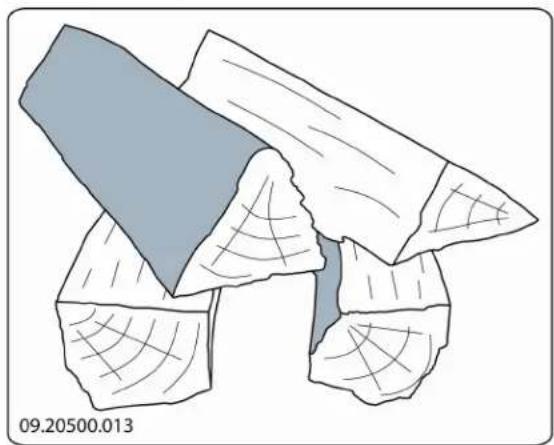
- Stack a few logs on the charcoal bed.
Open stacking
natural_image
Illustration of a broken or damaged object with grid patterns, no visible text or symbolsIf the logs are stacked openly, the wood will burn quickly as the oxygen can reach each log easily. If you want to use the stove for a short while, make an open stack.
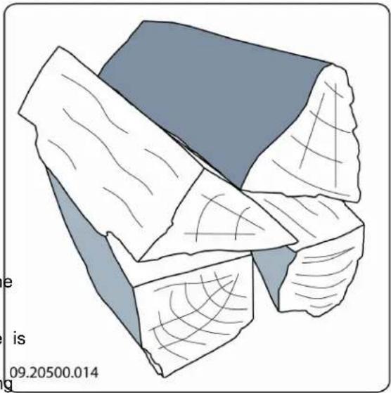
Compact stacking
natural_image
Illustration of a fragmented, irregularly shaped rock or mineral fragment with visible grain patterns (no text or symbols)If the logs are stacked tightly, the wood will burn more slowly as the oxygen can only reach some logs easily. If you want to burn wood for a longer period, make a compact stack.
- Close the door of the appliance.
- Close the primary air inlet and leave the secondary air inlet open.
⚠️ Fill the appliance up to one third capacity.
Controlling the air
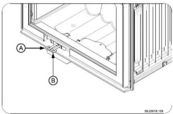
The appliance has various features for the air control (see figure).
text_image
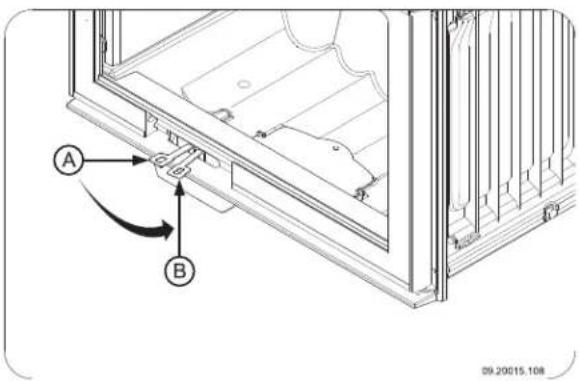
A B 99.20015.109The primary air slide (A) regulates the air below the grate. The secondary air slide (B) regulates the air for the glass (air wash).
Turn the air slide (A) to the left to open it; see next figure.
text_image
A B 09.20015.113intensely, so that layers of tar and creosote disappear.
Low intensity fires also cause tar deposits on the stove window and door.
When the outside temperature is not very low, it is better to burn wood intensely for a few hours instead of having a low intensity fire for a long period of time.
▶ Control the air supply with the secondary air inlet.

The secondary air inlet not only supplies air to the fire but to the glass as well, so that it does not get dirty so quickly.
▶ Open the primary air inlet for the time being if the supply by the secondary air inlet is inadequate or if you want to fan the fire.
It is better to add a small amount of logs regularly
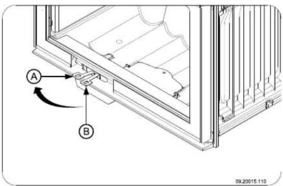
Turn the air slide (B) to the right to open it; see figure.
text_image
A B 09.20015.108The appliance is fitted with a double baffle plate permanent vent holes to ensure secondary combustion.
Advice

Never burn wood with an open door.

Regularly burn wood with intense roaring fires
Extinguishing the fire
Do not add fuel and just let the fire go out. If a fire is damped down by reducing the supply of air, harmful substances will be produced and released. Therefore, let the fire go out naturally. Keep an eye on the fire until it has gone out. When the fire has died completely, all air inlets can be closed.
Removing ashes
After wood has been burnt, a relatively small amount of ash remains behind. This bed of ash is a good ifhsulator for the fire plate and gives better combustion. So you can leave a thin layer of ash on the fire plate.
The flow of air through the fire plate must not be obstructed, however, and no ash may be allowed to accumulate behind a cast-iron inner plate. Remove the excess ash regularly.
Removing ash in models 2175 and 2575
If you frequently have low intensity fires, tar and creosote may be deposited in the chimney. Open the door of the appliance.
Tar and creosote are highly combustible substances. Thicker layers of these substances might catch fire when the temperature in the chimney increases suddenly and steeply. Therefore it is necessary for the fire to regularly burn very
- Scoop the excess ash from the appliance or use a special ash vacuum cleaner to remove the excess ash.

Always use an ash vacuum cleaner; using an ordinary vacuum cleaner that has not been specially modified can cause serious damage to an ordinary vacuum cleaner.
- Close the door of the appliance.
Ash removal in models 2176 2576
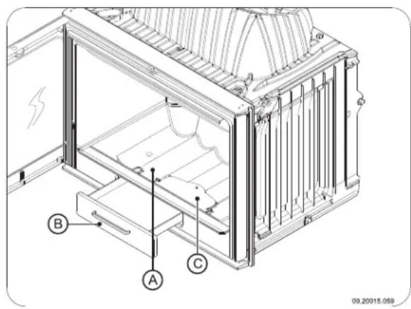
text_image
Technical diagram of a mechanical device with labeled components A, B, and C, showing internal structure and mounting points.- Open the door of the appliance.
- Use the scraper to open the ash removal port (in the bottom of the fire compartment (A).
- Scrape the excess ash through the ash removal port into the ashpan (B) below it.
- Close the ash removal port.
- Using the glove supplied, remove the ashpan (B) and empty it.
- Put back the ashpan and close the door of the appliance.
Fog and mist
Fog and mist hinder the flow of flue gases through the flue. Smoke can blow back and cause a stench. If this fire-resistant inner plates are consumables and not strictly necessary, it is better not to use the stove object to wear. Check the fire-resistant inner plates in foggy and misty weather. frequently and replace them when necessary.
Solving problems
Refer to the appendix "Diagnostic diagram" to solve any problems in using the appliance.
Maintenance
Follow the maintenance instructions in this chapter to keep the appliance in good condition.
Chimney
and many countries, people are legally required to have their chimney checked and maintained.
At the beginning of the heating season: have the chimney swept by an expert.
During the heating season and after the chimney has not been used for a long time: have the chimney checked for soot deposits.
▶ After the heating season: seal off the chimney with a ball of paper.
Cleaning and other regular maintenance activities

Do not clean the appliance when it is still warm.
▶ Clean the exterior of the appliance with a dry lint- (C) free cloth.
At the end of the heating season, you can clean the interior of the appliance thoroughly:
If necessary, first remove the fire-resistant inner plates. See the chapter "Installation" for instructions on removing and installing the inner plates.
▶ If necessary, clean the air supply ducts.
Remove the baffle plate at the top of the appliance and clean it.
Checking fire-resistant inner plates
This fire-resistant inner plates are consumables and ovebject to wear. Check the fire-resistant inner plates frequently and replace them when necessary.
▶ See the chapter "Installation" for instructions on removing and installing the inner plates.

The insulating vermiculite inner plates may develop hairline cracks, but that does not affect their performance adversely.

Cast-iron inner plates go a long way if you frequently remove the ash that may pile up behind them. If accumulated ash behind a cast-iron plate is not removed, the plate can dissipate the heat anymore to its surrounding and that may cause the plate to warp or cl

Never use the appliance without the fire-resistant inner plates.
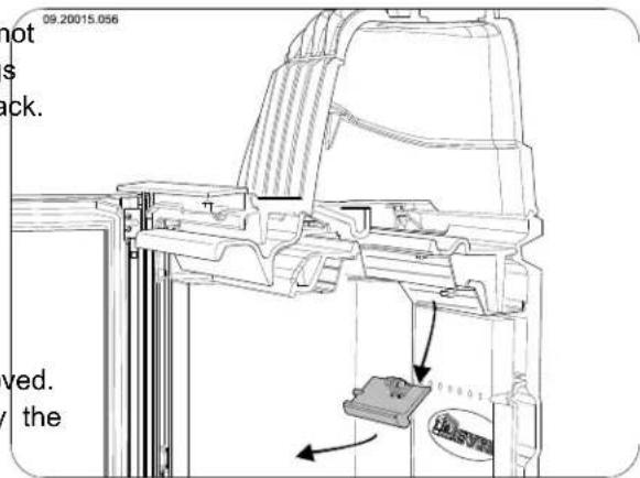
Dismantling damper and baffle plate
Both the damper and the baffle plate can be removed. The damper (A) is connected to the baffle plate by the damper rod. The baffle plate is fastened to the appliance with a bolt connection; see next figure.
- The damper is now loose. Take the damper out of the appliance; see next figure.
text_image
09.20015.056 not s ck. ved. the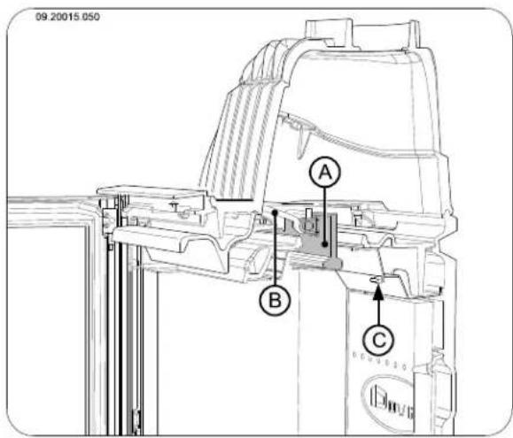
text_image
09.20015.050 A B C-
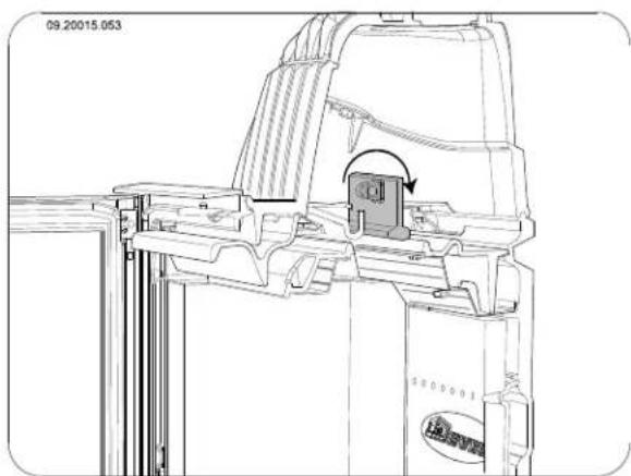
Lift the damper (A) and remove the damper rod from the damper. Tilt the damper backward; see next figure.
-
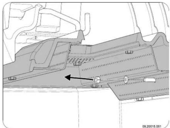
To remove the baffle plate, first unscrew the bolt (C). Loosen the nut; see next figure.
natural_image
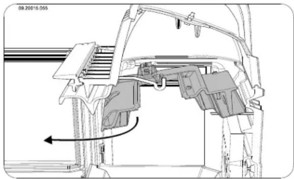
Technical diagram of a vehicle interior showing structural components and a directional arrow indicating movement (no text or symbols present)- Lift the baffle plate on the front side, pull the baffle plate forward and slide the baffle plate off the bolt; see next figure.
natural_image
Technical line drawing of a mechanical assembly with no visible text or symbols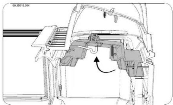
natural_image
Technical line drawing of a mechanical assembly with internal components and an arrow indicating motion (no text or symbols)- The baffle plate is now loose. Carefully take the Lubrication baffle plate out of the appliance; see next figure.
natural_image
Technical line drawing of a mechanical assembly with no visible text or symbols
Before using the appliance, fit the baffle plate and the damper. To fit the damper and the c baffle plate, follow the above instructions in the reverse order.
Cleaning glass
Dirt clings less easily to well-cleaned glass. Proceed as follows:
- Remove dust and loose soot with a dry cloth.
- Clean the glass with stove window cleaner:
a. Apply stove window cleaner to a kitchen sponge, rub down the entire glass surface and give the cleaning agent time to react.
b. Remove the dirt with a moist cloth or kitchen tissue.
- Clean the glass again with a normal glass cleaning product.
- Rub the glass clean with a dry cloth or kitchen tissue.
▶ Do not use abrasive or aggressive products to clean the glass.
▶ Wear household gloves to protect your hands.

If the glass in the appliance is broken or cracked, it must be replaced before you can use the appliance again.

Make sure that no stove window cleaner runs between the glass and the cast-iron door.
Lubrication
Although cast-iron is slightly self-lubricating, you will still have to lubricate moving parts frequently.
Lubricate the moving parts (such as guide systems, hinge pins, latches and air slides) with heat resistant grease that is available in the specialist trade.
Touching up the finish
Small areas of damaged paint finish can be touched up with a spraying can of special heat-resistant paint finish available from your supplier.
Checking the seal
Check whether the sealing rope of the door is still in good condition and works well. The sealing rope is subject to wear and needs to be replaced in time.
Check the appliance for air leaks. Close any chinks with stove sealant.

Let the sealant harden fully before you start a fire in the appliance, because otherwise any moisture in the sealant will form bubbles in the sealant and cause a new air leak.
Appendix 1: Technical Data
| Model Series 2170CB and 2570CB | |
| Rated output 10 kW | |
| Chimney connection (diameter) 150 mm | |
| Weight +/- 160 kg | |
| Recommended fuel Wood | |
| Fuel property, max. length 50 cm | |
| Flue gas flow rate | 10.1 g/s |
| Temperature rise measured in the measuring section | 260 K |
| Temperature measured at the appliance outlet | 345 °C |
| Minimum draught | 12 Pa |
| CO emission (13% _2 ) | 0,06 % |
| NOx emission (13% _2 )D | 118 mg/Nm ^3 |
| CnHm emission (13% _2 ) | 70 mg/Nm ^3 |
| Particulate emission | 19 mg/Nm ^3 |
| Particulate emission to NS3058-NS3059 | 7.1 g/kg |
| Efficiency | 75,9 % |
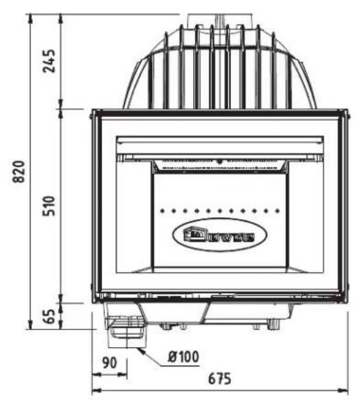
Appendix 2: Dimensions
2175CBS
text_image
245 820 510 65 90 Ø100 675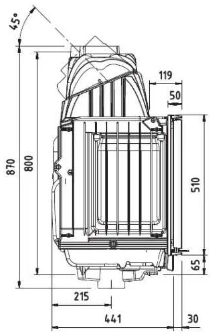
text_image
45° 870 800 119 50 510 65 215 441 30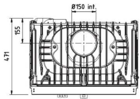
text_image
Ø150 int. 155 47109.20017.004
2176CBS
09.20017.047
2175CBS3
09.20017.006
2576CBS
text_image
25 600 95 Ø100 670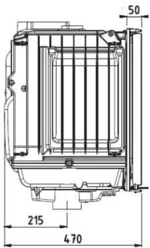
text_image
50 215 470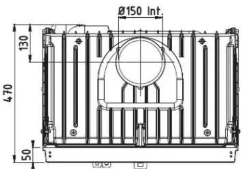
text_image
Ø150 Int. 130 4.70 5009.20017.001
2575CBS3
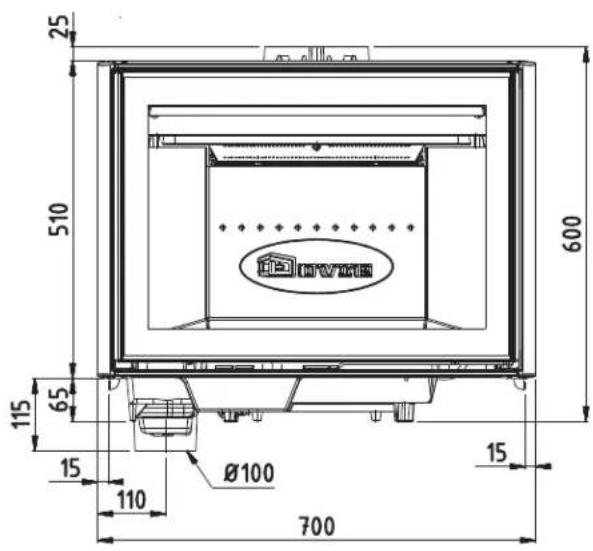
text_image
25 510 600 115 65 15 110 Ø100 700 15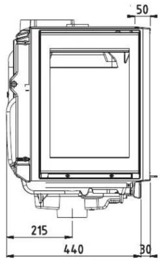
text_image
50 215 440 30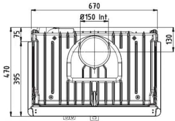
text_image
670 Ø150 Int. 75 470 395 13009.20017.003
Appendix 3: Distance from combustible material
Minimum ventilation outside the radiation range
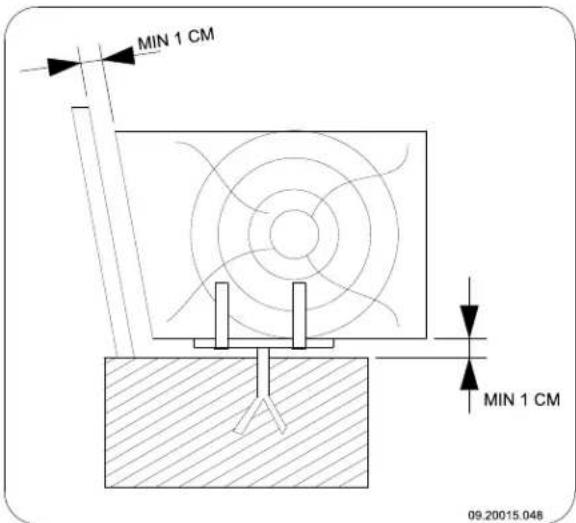
text_image
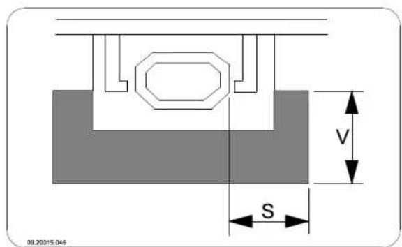
MIN 1 CM MIN 1 CM 09.20015.048Dimensions fireproof floor plate in centimetres
text_image
09.20015.046 V S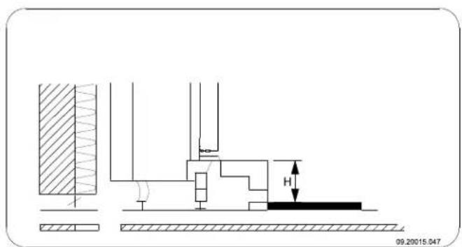
text_image
09.20015.047Minimum dimensions fireproof floor plate
$$ V > H + 3 0 > 6 0 $$
$$ S > H + 2 0 > 4 0 $$
Appendix 4: Diagnostic diagram
| Problem | ||||||
| ● | Wood does not keep burning | |||||
| ● | Gives off insufficient heat | |||||
| ● | Smoke emissions into the room when adding wood | |||||
| ● | Fire in appliance is too intense, is hard to adjust | |||||
| ● | Deposit on the glass | |||||
| Possible cause Possible | solution | |||||
| ● | ● | ● | ● | Insufficient draught | A cold flue usuallyfails to create sufficient draught. Follow the instructions for lighting in the "Use" chapter; open a window. | |
| ● | ● | ● | ● | Wood too damp Use wood with no more than 20% moisture. | ||
| ● | ● | ● | ● | Pieces of wood too big | Use smallpieces of kindling. Use split logs no larger than 30 cm in circumference. | |
| ● | ● | ● | ● | ● | Wood stacked up incorrectly | Stackup the wood in a way that allows an adequate air flow between the logs (open stacking, see "Burning wood") |
| ● | ● | ● | ● | Chimney does not work properly | Check whether the chimney meets the requirements: at least 4 metres high, right diameter, well insulated, smooth inside, not too many bends, no obstructions in chimney (bird'snest, too much soot deposit), hermetically tight (no chinks). | |
| ● | ● | ● | ● | Chimney stack incorrect Sufficiently high above the roof, no obstacles in its vicinity | ||
| ● | ● | ● | ● | ● | Air inlets set incorrectly Open the air | inletscompletely. |
| ● | ● | ● | ● | Appliance connected to chimney incorrectly | Connection should be hermetically tight. | |
| ● | ● | ● | ● | Vacuum in area where appliance is installed | Switch off extraction systems. | |
| ● | ● | ● | ● | Insufficient supply of fresh air | Provide an adequate air supply; if necessary use connection to outside air. | |
| ● | ● | ● | ● | Adverse weather conditions? Inversion (reversed air flow in chimney)We recommend you don't use the appliance in the case of inversion. because of a high outside temperature install an extra hood on the flue to increase the draught if need be extreme wind velocities | ||
| ● | Draught in the living room | Avoid draught in the living room, do not place the appliance near a door or heating air ducts. | ||||
| ● | Flames touch the glass | Make sure the wood does not lie too close to the glass. Slide the primary air inlet cover closer to the "Closed" position. | ||||
| ● | Appliance is leaking air Check the door seals and the appliance joints. | |||||
Index
A
Adding fuel 13
Adding wood smoke emissions into the roam 24....
Air control.12....
Air inlet grate placing .10. requirements .10.
Air inlets.12....
Air leak 16
Air outlet grate placing 10..... requirements..10....
Air supply for fire 13
Ash removal port 14....
Ashes remove .13....
Ashpan opening.... 14
B
Baffle plate fitting....15
Bearing capacity of floor Floors bearing capacity 5
Burning wood.... 12 add fuel..13..... adding logs.... 12 appliance is hard to adjust.... 24 fire is too intense.... 24 insufficient heat.... 14, 24
C
Carpet 5
Chimney connection diameter.... 17 connection to.... 9 height.... 5 sweep.... 14
Chinks in appliance.... 16
Clean glass....16
Cleaning appliance.... 14
Closing plate convection space 10
Combustible material distance from 23
Connection collar.... 7
Connection to supply of outside air 8
Connections dimensions 18
Control air supply.... 13
Control of air 12
Convection space cover plate....10 instructions....9
Cover on flue 5
Creosote....13
D
Damp wood.... 11
Damper fitting....15
Dimensions 18
Door changing swing direction.... 6 sealing rope.... 16
Draught 17
Drying of wood.... 11
E
Efficiency.... 17
F
Filling height.... 12
Finishing coat, maintenance 16
Fire extinguishing....13 lighting..11.....
Fire-resistant inner plates maintenance 14....
Fire going out 13
Fire safety distance from combustible material.... 23 floor.... 5 furniture.... 5 walls.... 5
Fireproof inner plates
warning 11
Floors
fire safety 5
Flue
maintenance 14
requirements.4....
Flue gas
flow rate.17....
Fog, do not burn wood..14
Fuel
adding 13
adding wood 12
necessary amount 14
suitable.1.1
unsuitable 11
G
Glass
clean .16....
deposit 24
H
Heat, insufficient 14
Heat,insufficient....24
Hood on the flue 5
|
Inner plates
removal....7
Inner plates, fireproof 7
K
Kindled fire 11
Kindling....24
L
Lighting 11
Lubricant 16
Lubricate.... 16
M
Maintenance
chimney 14
clean glass.... 16
cleaning the appliance.... 14
fire-resistant inner plates.... 14
lubrication 16
sealing.16
Mist, do not burn wood 14
N
Nominal output 14
0
Open
ash removal port.... 14
Opening
ashpan....14
Outside air intake
connection to.... 9
P
Paint finish.... 11
Particulate emission 17
Placing
dimensions 18
Prevent a chimney fire.... 13
Primary air inlet 12
R
Rated output 17
Removal of ashes.... 13
Remove ashes 13
s
Scraper for ash removal 14
Screens
clean 16
deposit.24
Sealing rope for door 16
Secondary air inlet 12
Side glass 6
Side panel
conversion 6
Smoke
on first use 11
Smoke emissions into the room.... 4, 24
Softwood 11
Solving problems.... 14, 24
Stacking logs 12
Storing wood.... 11
Stove window cleaner 16
Suitable fuel 1.1
Supply of outside air 5, 8
Sweep chimney 14
Swing direction
changing.6
T
Tar.13....
Temperature 17
Temperature rise
measuring section 17
U
Unsuitable fuel 11
V
Ventilation 5
connect supply of outside.air.... 8
rule of thumb 5
Ventilation louvre 5
W
Walls
fire safety 5
Warning
chimney fire 4, 11, 13
combustible materials.... 4
fireproof inner plates 11
glass broken or cracked 4, 16
hot surface 4
regulations....4
stove window cleaner 16
terms and conditions for insurance.... 4
ventilation 4-5
Weather conditions, do not burn wood..... 14
Weight 17
Wood 11
damp 11
does not keep burning.... 24
drying 11
right sort.... 11
storing 11
Table des matières
Introduction 3
natural_image
Technical line drawing of a mechanical device with internal components and a close-up inset showing internal assembly (no text or symbols)natural_image
Technical line drawing of a mechanical assembly with internal components (no text or symbols)natural_image
Illustration of layered geological strata with no visible text or symbolsnatural_image
Illustration of a sliced food item with visible grain patterns (no text or symbols)natural_image
Illustration of fragmented, irregularly shaped objects with internal patterns, no text or symbols presenttext_image
Technical diagram of a battery pack assembly with labeled components A, B, and Cnatural_image
Technical diagram of a vehicle intake structure with no visible text or symbolsnatural_image
Technical line drawing of a mechanical assembly with internal components and an arrow indicating direction (no text or symbols)natural_image
Technical line drawing of a mechanical assembly with no visible text or symbols
natural_image
Technical line drawing of a mechanical cage assembly with internal components and a close-up inset showing a tool (no text or symbols present)natural_image
Technical line drawing of a mechanical assembly with internal components and mounting bracket (no text or symbols)text_image
09.20015.043 A B C D E F G H I N J K O 3 cm L Mnatural_image
Illustration of layered geological strata with no visible text or symbolsnatural_image
Illustration of a broken stone or mineral sample with visible grain patterns (no text or symbols)natural_image
Illustration of a composite material with layered textures and patterns (no text or symbols)natural_image
Technical line drawing of a mechanical assembly with no visible text or symbolsnatural_image
Technical line drawing of a mechanical assembly with no visible text or symbolsnatural_image
Technical diagram of a vehicle interior showing structural components and a directional arrow (no text or symbols)natural_image
Technical line drawing of a mechanical assembly with internal components and an arrow indicating motion (no text or symbols)natural_image
Technical line drawing of a mechanical assembly with no visible text or symbols
Schornsteinbrand 4, 11, 14
Ventilation 4
Vorschriften 4
Wartung
Abdichtung 17
natural_image
Technical line drawing of a mechanical device with internal components and a close-up inset showing internal assembly (no text or symbols)natural_image
Technical line drawing of a mechanical assembly with internal components and mounting bracket (no text or symbols)text_image
(C): 100 100 09.20015.040natural_image
Illustration of layered geological strata with no visible text or symbolsnatural_image
Illustration of a broken stone with visible grain patterns and a blue rectangular block, no text or symbols present.natural_image
Illustration of a broken stone or mineral sample with visible grain patterns and texture (no text or symbols)natural_image
Technical diagram of a vehicle chassis with structural components and a directional arrow indicating movement (no text or symbols present)natural_image
Technical line drawing of a mechanical assembly with internal components and an arrow indicating motion (no text or symbols)natural_image
Technical line drawing of a mechanical assembly with no visible text or symbols
natural_image
Technical line drawing of a mechanical assembly with internal components and mounting bracket (no text or symbols)natural_image
Illustration of layered geological strata with a central pebble formation (no text or symbols)natural_image
Illustration of a textured, folded object resembling a tool or fabric (no text or symbols)natural_image
Illustration of fragmented stone or mineral fragments with visible grain patterns (no text or symbols)text_image
Technical diagram of a battery pack with labeled components A, B, and C, showing internal structure and mounting points.natural_image
Technical diagram of a vehicle interior showing structural components and a directional arrow (no text or symbols present)natural_image
Technical line drawing of a mechanical assembly with internal components and a directional arrow (no text or symbols)natural_image
Technical line drawing of a mechanical assembly with no visible text or symbols