Sense 403 - Heating DOVRE - Free user manual and instructions
Find the device manual for free Sense 403 DOVRE in PDF.
Frequently Asked Questions - Sense 403 DOVRE
User questions about Sense 403 DOVRE
0 question about this device. Answer the ones you know or ask your own.
Ask a new question about this device
Download the instructions for your Heating in PDF format for free! Find your manual Sense 403 - DOVRE and take your electronic device back in hand. On this page are published all the documents necessary for the use of your device. Sense 403 by DOVRE.
USER MANUAL Sense 403 DOVRE
natural_image
Modern white portable stove with visible flames and black interior (no text or symbols)
natural_image
Black industrial stove burner with visible flame inside (no text or symbols)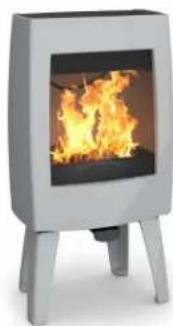
natural_image
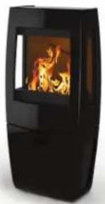
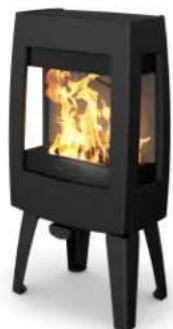
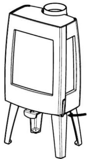
Modern outdoor stove with visible flames and legs (no text or symbols)Sense 300 Sense 303 Sense 400 Sense 403
natural_image
Black portable stove with visible flames and wooden legs (no text or symbols)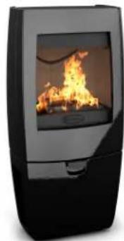
natural_image
Black and white photo of a portable stove burner with visible flames (no text or symbols)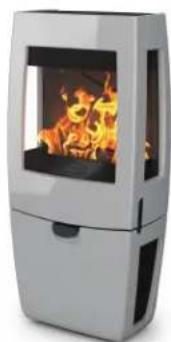
natural_image
Modern portable stove burner with visible flames and black vent, no text or symbols presentSense
Inhoudsopgave
Inleiding 3
text_image
Technical diagram of a portable stove or vent with numbered parts labeled 1 to 509-20021-009
text_image
Technical diagram of a device with numbered parts labeled 1 to 509-20021-010
natural_image
Line drawing of a simple electrical enclosure with four legs and a top opening (no text or symbols)09-20021-012
natural_image
Technical line drawing of a mechanical component with a labeled tool (1), no readable text or symbols present.Hitteschild monteren
natural_image
Illustration of layered geological strata with visible stratification and a central fracture (no text or symbols)natural_image
Line drawing of a four-legged stool with a handle and mounting feet (no text or symbols)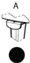
C:
natural_image
Illustration of a textured, irregularly shaped object with no visible text or symbols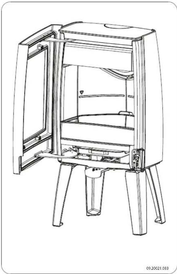
natural_image
Technical line drawing of a mechanical device with open door and four legs (no text or symbols)Stoken met hout
natural_image
Illustration of a broken stone or mineral sample with visible grain patterns and texture (no text or symbols)schoorsteenbrand 10, 16, 19
ventilatie 10-11
Performance declaration 4
Performance declaration 6
Performance declaration 8
Safety 10
Installation requirements 10
General 10
Flue 10
Room ventilation 11
Floor and walls 11....
Product description 12
Installation 13
General preparation.... 13
Preparing the connection to the flue.... 14
Preparing the outside air connection.... 15
Installing and connecting 15
Use 16
First use.... 16
Fuel 16
Lighting 16
Maximum amount of wood 17
Burning wood 18
Controlling combustion air.... 19
Extinguishing the fire.... 19
Removing ash 19
Fog and mist 20
Resolving problems 20
Maintenance 20
Flue 20 Cleaning and other regularly maintenance 20
Sense spare parts 23
Appendix 1: Technical data 24
Appendix 2: Dimensions 25
Appendix 3: Distance from combustible material 33
Appendix 4: Diagnosis diagram.... 38
Index 39
Introduction
Dear user,
By purchasing this heating appliance from DOVRE you have selected a quality product. This product is part of a new generation of energy-efficient and environmentally-friendly heating appliances. These appliances make optimum use of convection heat as well as thermal radiation (radiant heat).
Your DOVRE appliance has been manufactured with state-of-the-art production equipment. In the unlikely event of a malfunction, you can always rely on DOVRE for support and service.
The appliance should not be modified; please always use original parts.
The appliance is intended for use in a living room. It must be hermetically connected to a properly working flue.
We advise you have the appliance installed by an authorized and competent installer.
▶ DOVRE cannot be held liable for any problems or damage resulting from incorrect installation.
▶ Observe the following safety regulations when installing and using the appliance.
In this manual, you can read how the DOVRE heating appliance can be installed, used and maintained safely. Should you require additional information or technical data, or should you experience an installation problem, please first contact your supplier.
© 2014 DOVRE NV
Performance declaration
In accordance with construction products regulation 305/2011
No. 033-CPR-2013
- Unique identification code of the product type:
Sense 100 - 200 / 4.9 kW
- Type, batch or serial number or other form of identification for the construction product, as scribed in article 11, subsection 4:
Unique serial number.
- Intended use for the construction product, in accordance with the applicable harmonised techr specification, as specified by the producer:
Stove for solid fuel without production of warm water in accordance with EN 13240.
- Name, registered trade name or registered trademark and contact address of the producer, as scribed in article 11, subsection 5:
-
If applicable, name and contact address for the authorised whose mandate covers the tasks cified in article 12, subsection 2:
-
The system or systems for the assessment and verification of the performance durability of struction product, specified in appendix V:
System 3
- If the performance declaration refers to a construction product that falls under a harmonised ard:
The appointed agency ARGB/KVBG, registered under the number 2013, has performed a type test under system 3 and has issued the test report no. H20130113.
-
If the performance declaration concerns a construction product for which a European technical assessment is issued:
-
Declared performance:
| The harmonised norm EN 13240:2001/A2 ;2004/AC :2007 | |
| Essential characteristics Performance Wood | |
| Fire safety | |
| Fire resistance A1 | |
| Distance from combustible material | Minimum distance in mmRear: 300Side: 500 |
| Risk of glowing particles falling out Conform | |
| Emission of combustion products CO: 0.18% (13%O2) | |
| Surface temperature | Conform |
| Electrical safety | - |
| Ease of cleaning | Conform |
| Maximum operating pressure | - |
| Flue gas temperature at nominal output | 247 °C |
| Mechanical resistance (carrying weight of chimney) | Not determined |
| Nominal output | 4.9 kW |
| Efficiency | 79.5% |
- The performance of the product described in points 1 and 2 conform with the performance in point 9.
This performance declaration is supplied under the exclusive responsibility of the producer specifi in point 4:

text_image
T. Gehem01/10/2013 Weelde
Tom Gehem CEO
Due to continuous product improvement, the supplied appliance specifications may vary from the description in this brochure without prior notice having been given.
DOVRE N.V.
Performance declaration
In accordance with construction products regulation 305/2011
No. 032-CPR-2013
- Unique identification code of the product type:
Sense 100 - 200 / 7 kW
- Type, batch or serial number or other form of identification for the construction product, as scribed in article 11, subsection 4:
Unique serial number.
- Intended use for the construction product, in accordance with the applicable harmonised techr specification, as specified by the producer:
Stove for solid fuel without production of warm water in accordance with EN 13240.
- Name, registered trade name or registered trademark and contact address of the producer, as scribed in article 11, subsection 5:
-
If applicable, name and contact address for the authorised whose mandate covers the tasks cified in article 12, subsection 2:
-
The system or systems for the assessment and verification of the performance durability of struction product, specified in appendix V:
System 3
- If the performance declaration concerns a construction product that falls under a harmonised
The appointed KVBG instance, registered under the number 2013, has performed a type test under system 3 and has issued the test report no. H20130112.
-
If the performance declaration concerns a construction product for which a European technical assessment is issued:
-
Declared performance:
| The harmonised norm EN 13240:2001/A2 ;2004/AC :2007 | |
| Essential characteristics Performance Wood | |
| Fire safety | |
| Fire resistance A1 | |
| Distance from combustible material | Minimum distance in mmRear: 300Side: 500 |
| Risk of glowing particles falling out Conform | |
| Emission of combustion products CO: 0.07% (13%O2) | |
| Surface temperature | Conform |
| Electrical safety | - |
| Ease of cleaning | Conform |
| Maximum operating pressure | - |
| Flue gas temperature at nominal output | 274 °C |
| Mechanical resistance (carrying weight of chimney) | Not determined |
| Nominal output | 7 kW |
| Efficiency | 80.0 % |
- The performance of the product described in points 1 and 2 conform with the performance in point 9.
This performance declaration is supplied under the exclusive responsibility of the producer specifi in point 4:
text_image
T. Gehem01/10/2013 Weelde
Tom Gehem CEO
Due to continuous product improvement, the supplied appliance specifications may vary from the description in this brochure without prior notice having been given.
DOVRE N.V.
Performance declaration
In accordance with construction products regulation 305/2011
No. 041-CPR-2014
- Unique identification number of the product type:
Sense 300 - 400 / 9 kW
- Type, batch or serial number or other form of identification for the construction product, as scribed in article 11, subsection 4:
Unique serial number.
- Intended use for the construction product, in accordance with the applicable harmonised techr specification, as specified by the producer:
Stove for solid fuel without production of warm water in accordance with EN 13240.
- Name, registered trade name or registered trademark and contact address of the producer, as scribed in article 11, subsection 5:
-
If applicable, name and contact address for the authorised whose mandate covers the tasks cified in article 12, subsection 2:
-
The system or systems for the assessment and verification of the performance durability of struction product, specified in appendix V:
System 3
- If the performance declaration refers to a construction product that falls under a harmonised ard:
The appointed agency ARGB/KVBG, registered under the number 2013, has performed a type test under system 3 and has issued the test report no. H20140117.
-
If the performance declaration concerns a construction product for which a European technical assessment is issued:
-
Declared performance:
| The harmonised norm EN 13240:2001/A2 ;2004/AC :2007 | |
| Essential characteristics Performance Wood | |
| Fire safety | |
| Fire resistance A1 | |
| Distance from combustible material | Minimum distance in mmRear: 400Side: 500 |
| Risk of glowing particles falling out Conform | |
| Emission of combustion products CO: 0.08% (13%O2) | |
| Surface temperature | Conform |
| Electrical safety | - |
| Ease of cleaning | Conform |
| Maximum operating pressure | - |
| Flue gas temperature at nominal output | 216 °C |
| Mechanical resistance (carrying weight of chimney) | Not determined |
| Nominal output | 9 kW |
| Efficiency | 80 % |
- The performance of the product described in points 1 and 2 conform with the performance in point 9.
This performance declaration is supplied under the exclusive responsibility of the producer specifi in point 4:

text_image
T. Gehem01/10/2013 Weelde
Tom Gehem CEO
Due to continuous product improvement, the supplied appliance specifications may vary from the description in this brochure without prior notice having been given.
DOVRE N.V.
Please note: All safety regulations must be complied with strictly.

Please read carefully the instructions supplied with the appliance for installation, use and maintenance before using the appliance.

The appliance must be installed in accordance with the legislation and requirements applicable in your country.

All local regulations and the regulations relating to national and European standards must be observed when installing the appliance.

The appliance should preferably be installed by an authorised installer. Installers will be aware of the applicable regulations and requirements.

The appliance is designed for heating purposes. All surfaces, including the glass and connecting tube, can become very hot (over 100°C)! When operating, use a so-called "cold hand" or an oven glove.

Ensure that the appliance is adequately guarded if young children, disabled people, the elderly or animals are present in the vicinity.

Safety distances from flammable materials must be strictly adhered to.

Do not place any curtains, clothes, laundry or other combustible materials on or near the appliance.

When in use, do not use flammable or explosive substances in the vicinity of the appliance.

Avoid chimney fires by having the chimney swept regularly. Never burn wood with the door open.

In the event of a chimney fire: close all the appliance's air inlets and alert the fire service.

If the glass in the appliance is broken or cracked, it must be replaced before the stove is used again.

Do not exert force on the door, do not allow dren to pull on the opened door, never stand sit on the opened door and do not place heat
objects on the door. This is to avoid the possibility of the appliance tipping.

Ensure that there is adequate ventilation in the room in which the appliance is installed. If ventilation is insufficient, combustion will be incomplete whereby in toxic gases can spread through the room. See the chapter "Installation requirements" for more information on ventilation.
Installation ng requirements
General
The appliance must be connected tightly to a well-functioning flue.

For connection measurements: see "Technical data" appendix.
Ask the fire service and/or your insurance company about any specific requirements and regulations.
Flue
The flue is needed for:

Removal of combustion gases via natural draught.

As the warm air in the flue or chimney is lighter than the outside air, it rises.

Air intake, needed for the combustion of fuel in the appliance.

poorly-functioning flue or chimney can cause smoke escape into the room when the door is opened. Damage caused by smoke emissions into the room is not covered by the warranty.

Do not connect multiple appliances (such as a boiler for central heating) to the same flue, unless local or national regulations allow this. In the event of two connections ensure that the difference in height between the connections is no less than 200 mm.

Ask your installer for advice regarding the flue. Refer / the European norm EN13384 for a correct cal-lations for the flue.
The flue must satisfy the following requirements:
The flue or chimney must be made of fire-resistant material, preferably ceramics or stainless steel.
The flue or chimney must be airtight and well-cleaned and guarantee sufficient draught.
A draught/vacuum of 15 - 20 Pa during normal operation is ideal.
Starting from the flue spigot, the flue must run a vertically as possible. Changes in direction and horizontal pieces disrupt the outward flow of combustion gases and may cause soot deposits.
To prevent combustion gases from cooling down For good combustion, the appliance needs air (oxy-too much, which reduces the draught, ensure that gen). This air is supplied via adjustable air inlets from the interior diameter is not too big. the area in which the appliance is installed.
The flue or chimney should ideally have the same⚠️. If ventilation is insufficient, combustion will be diameter as the connection collar. Incomplete, which may lead toxic gases to
i
For nominal diameter: see "Technical data" appendix. If the smoke channel is well insulated, the diameter may be slightly bigger (u 2x the section of the connection collar).
As a rule of thumb, the air supply should be 2519 cm²/kW. Extra ventilation is needed when:
The section (area) of the smoke channel must constant. Wider segments and (in particular) narrower segments disrupt the outward flow of combustion gases.
In fitting a cover plate/exhaust cap to the flue: You can provide extra ventilation by having a vent-make sure that the cover does not restrict the fluation louvre fitted on the outside wall.
outlet and that the cap does not impede the outward flow of combustion gases.
The flue must end in a zone that is not affected from fan) have their own supply of outside air, or are surrounding buildings, trees or other obstacles. switched off when you use the appliance.
The flue outside the house must be insulated.
The flue should be at least 4 metres high.
As a rule of thumb: 60 cm above the ridge of the roof.
If the ridge of the roof is more than 3 metres from the flue: use the measurements given in the following figure. A = the highest point of the roof within a distance of 3 metres.
The appliance is in a well-insulated area.
There is mechanical ventilation, for example a central extraction system or an extraction hood in an open kitchen.
Make sure that other air consuming appliances (such as tumble-driers, other heating appliances or a bath-from fan) have their own supply of outside air, or are switched off when you use the appliance.
i
You can also connect the appliance to an outside air supply. A connection kit is supplied for this purpose. This makes additional ventilation unnecessary.
Floor and walls
The floor on which the appliance is placed must have sufficient bearing capacity. The weight of the appliance is given in the appendix "Technical Data appendix".
[NO TEXT]
Protect flammable flooring from heat radiation by means of a fireproof protective plate. See

the appendix "Distance from combustible material".

Remove combustible material such as lino- leum, carpets/rugs and similar materials below the fireproof protective plate.

Keep sufficient distance between the appliance and combustible materials such as wooden walls and furniture.

The connecting tube also radiates heat. Ensure that there is sufficient distance or a shield between the connecting tube and combustible material.
The rule of thumb for a single-walled tube is a distance of 3x the diameter. If a lining shell is fitted around the tube, a distance of 1x the diameter is permissible.

Carpets and rugs must be at least 80 cm away from the fire.

Use a fireproof floor plate to protect a flammable floor from any ash which may fall in front of the stove. The floor plate must comply with national standards.

For the dimensions of the fireproof protective plate: see the appendix "Distance from combustible material".

For further requirements with respect to fire safety, see the appendix "Distance from combustible material".
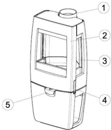
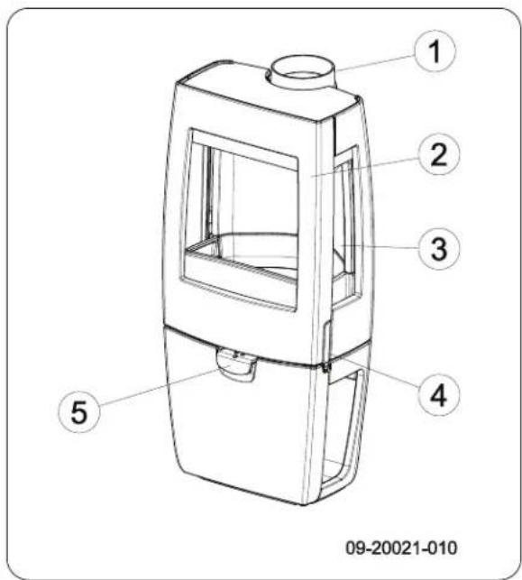
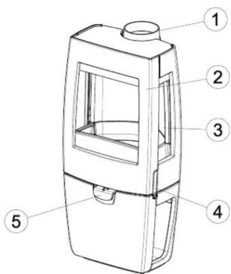
Product description
text_image
Technical diagram of a portable stove with numbered parts labeled 1 to 509-20021-009

text_image
Technical diagram of a device with numbered parts labeled 1 to 509-20021-010
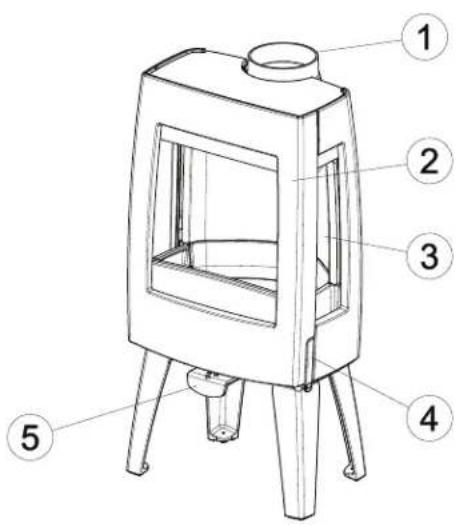
- Connection collar
- Door
- Side glass
- Latch
- Air slide
Door lock
The appliance is supplied with the latch button (4) installed. The door is opened by pressing in the latch button. As the latch button becomes warm during use, a glove has been supplied which you can use to protect your hand.
Installation
General preparation
Please check the appliance immediately after delivery for damage during transport or any other damage or defects. The appliance is attached to the pallet with screws at the bottom.

If you detect transport damage or any other damage or defects, do not use the appliance and notify the supplier.
Remove removable parts (fire-resistant inner plates, fire grate, top plate, ashtray) from the appliance before starting installation.

It is easier to move the appliance and to avoid damage if the removable parts have been removed.

Note the location of the removable parts, so that you can re-position the parts in the correct place later on.
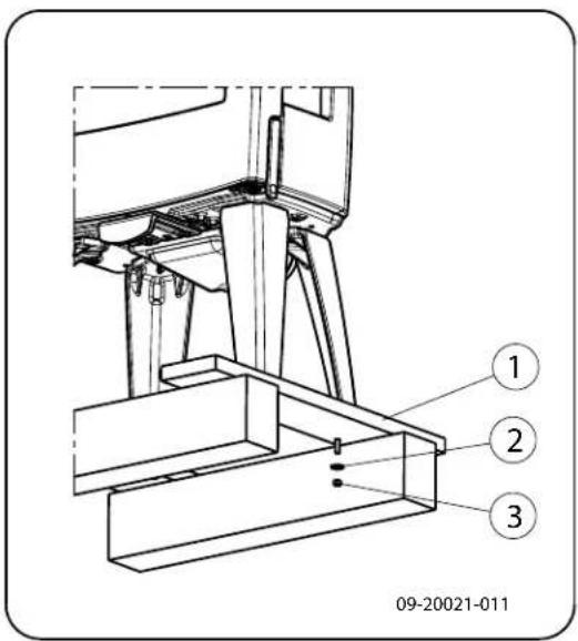
text_image
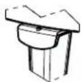
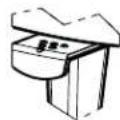
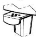
09-20021-011- Open the door; see the following figure:
natural_image
Line drawing of a simple portable stove or vent with four legs and a top lid (no text or symbols)09-20021-012
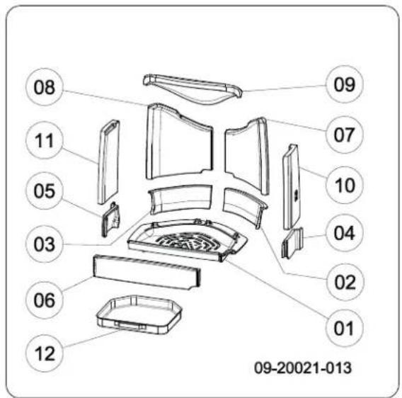
- Remove the fire-resistant inner plates; see the foloid lowing figure:
a. First remove the baffle plate (09).

The baffle plate is attached at the top with a metal clip. This is to avoid damage during transit.
b. Remove the inner plates (10), (11), (07) and (08) at the side and at the back.
c. Remove the fire basket at the side (02) and (03) and at the front (04), (05) and (06).
d. Remove the grate and the ash pan (01) and (12).

Vermiculite inner plates are light and tend to be ochrous in colour on delivery. They insulate the combustion chamber to boost combustion.

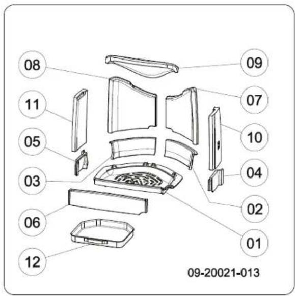
text_image
08 11 05 03 06 12 09 07 10 04 02 01 09-20021-013Removable internal parts
01 base plate
02 fire basket right rear
03 fire basket left rear
04 fire basket right
05 fire basket left
06 fire basket
07 side inner plate right rear
08 side inner plate left rear
09 baffle plate inner plate
10 side inner plate right
11 side inner plate left
12 ash pan
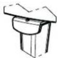
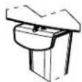
Preparing the connection to the flue
When connecting the appliance to the flue, you can choose to connect to the top or to the rear of the appliance
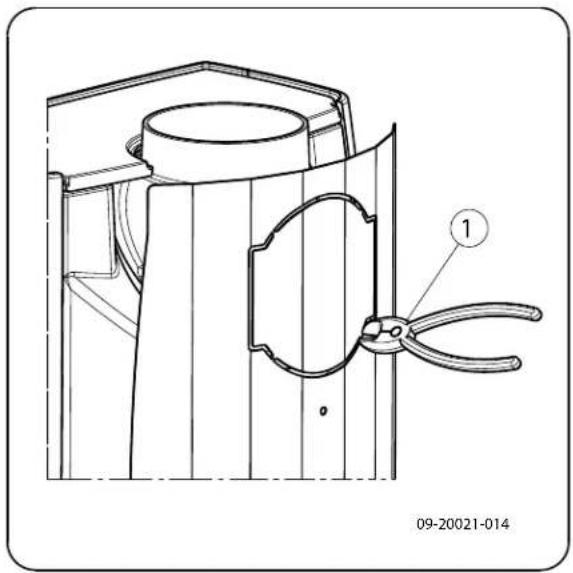
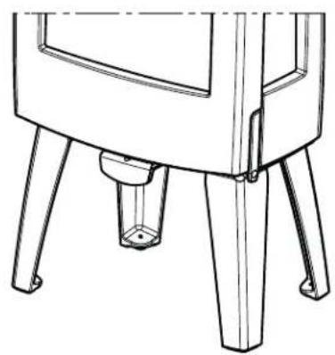
An optional heat shield is available. By using this heat shield you can reduce the distance to the combustible material. See appendix "Distance from combustible material". For a rear connection the escape plate needs to be removed. You can do this with the assistance of a screwdriver (1); see following figure.
natural_image
Technical line drawing of a mechanical component with a labeled part (1), no readable text or symbols present.Fitting the heat shield
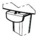
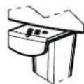
To fit the optional heat shield, proceed as follows:
- Screw 2 M6 studs (1) with spacer (2) to the rear wall.
- Place the heat shield (3) and screw into place with 2 M6 flanged cap screws (4), see following figure.
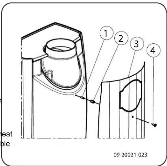
text_image
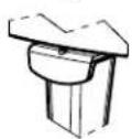
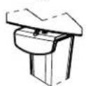
heat ble 1 2 3 4 09-20021-023Connecting to the top
As standard, the appliance is delivered with the connection collar fitted for a connection at the top, see following figure.
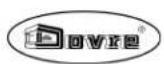
text_image
09-20021-015 ① ②Connecting to the rear
For a connection to the rear, the position of the connection collar needs to be changed. The connection collar is attached with 2 M8 nuts (key 13). Proceed P follows:
- First remove the baffle plate.
- Unscrew the nuts and remove the connection co lar.

Check that the sealing tape on the contact surface is not damaged. Replace the sealing tape if it is damaged.
- Place the connection collar turned 180^ with respect to its original position; see next figure.
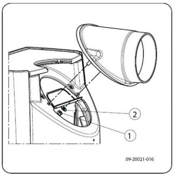
text_image
09-20021-016-
Fit the connection collar with the 2 M8 nuts.
-
Replace the baffle plate.
-
Fit the connection collar with the 2 M8 nuts.
- Replace the baffle plate.
Preparing the outside air connection
If the appliance is installed in a room with insufficient ventilation, you can install the outside air connecting kit to the appliance.
The air supply tube is 100 mm in diameter. If the tube is smooth, it may be no longer than 12 metres. If accessories such as bends are used, the maximum length (12 m) must be reduced by 1 m for each accessory used.
Outside air connection via the wall
-
Make an opening in the wall (see the appendix, "Measurements", for the correct position of the opening).
-
Close the air connection hermetically to the wall.
-
Make an opening in the wall (see the appendix, "Measurements", for the correct position of the opening).
- Close the air connection hermetically to the wall.
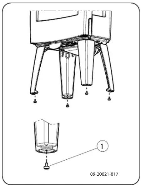
Installing and connecting
- Position the appliance in the correct place, and make sure it is level. The appliance is designed with adjustable feet, which may already be mounted on the appliance or be included. Use these adjustable feet so that the appliance can be placed perfectly level.

text_image
09-20021-017- Connect the appliance to the flue hermetically.
- For outside air supply connection: connect the outside air supply to the connection kit which is fitted to the appliance.
- Re-position all removed parts to the correct places in the appliance.

Never use the appliance without the fire-resistant inner plates.
The appliance is now ready for use.
Use
First use
When you use the appliance for the first time, make an intense fire and keep it going for a good few hours. This will cure the heat-resistant paint finish. This may result in some smoke and odours. You could open windows and doors for a while in the area in which the appliance is located.
Fuel
This appliance is only suitable for burning natural wood; sawn and chopped wood that is sufficiently Do not use other fuels, as they can cause serious damage to the appliance.
The following fuels may not be used as they pollute the environment, and because they heavily pollute the appliance and flue, which may lead to a chimney fire:
▶ Treated wood, such as scrap wood, painted wood, impregnated wood, preserved wood, plywood and chipboard.
Plastics, scrap paper and domestic waste.
Wood
Hardwood, such as oak, beech, birch and fruit tree wood is the ideal fuel for your stove. This type of wood burns slowly with calm flames. Softwood contains more resins, burns faster and sparks more.
▶ Use seasoned wood that contains no more than 20% moisture. The wood should have been seasoned for at least 2 years. Wood with a moisture content of 20% provides 4.2 kWh per kg wood. Wood with a moisture content of 15% provides 4.4 kWh per kg wood. Freshly felled wood has a moisture content of 60% and only provides 1.6 kWh per kg wood.
Saw the wood to size and split it while it is still fresh. Fresh wood is easier to split, and split wood dries more easily. Store the wood under a roof where the wind has free access.
Do not use damp wood. Damp logs do not produce heat as all the energy is used in the evaporation of moisture. This will result in a lot of smoke and soot deposits on the appliance door and in the flue. The water vapour will condense in the appliance and can leak away through chinks in the stove, causing black stains on the floor. It may also condense in the chimney and form creosote. Creosote is a highly flammable compound and may cause a chimney fire.
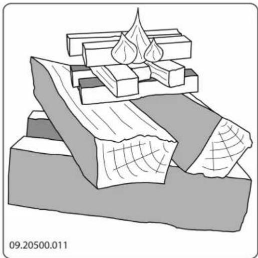
^1e Lighting
You can check whether the flue has sufficient draught by lighting a ball of paper above the baffle plate. A cold flue often has insufficient draught and consequently, some smoke may escape into the room instead of up the chimney. You can avoid this problem by lighting the fire as described below.
-
Stack two layers of medium sized logs crosswise
-
Stack two layers of kindling crosswise on top of the logs.
-
Place a firelighter cube in the lower layer of kindling and light the cube according to the instructions on the packaging.
natural_image
3D diagram of layered geological or material structure with no visible text or symbols-
Close the appliance door and open the primary and secondary air inlets; see the following figure.
-
Allow the fire develop into a good blaze until there is glowing bed of charcoal. You can then add fuel and adjust the appliance, see the chapter "Stoking" with wood".
natural_image
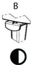
Line drawing of a four-legged stool with a handle and mounting feet (no text or symbols)A

B

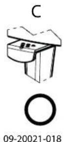
C

09-20021-018
C:
o o Primary air open (when lighting the stove)
o Secondary air open (glass wash)
o Air for post-combustion open
B:
o o Secondary air open (glass wash)
o Air for post-combustion open
A:
o Air for post-combustion open
(never close entirely for proper combustion)
Maximum amount of wood
To stoke continuously at the rated power, wood must be added every 45 minutes. If you use a smaller amount of wood each time, you can add wood more often. Each stove is designed to work with a specific maximum amount of wood. If you use a larger quantity of wood, the heat output increases. This can cause the hearth to be overloaded and parts can be damaged.

Allowable amount of fuel when using wood with a moisture content of 15%:
- Slowly open the door of the appliance.
- Spread the charcoal evenly across the bottom of the stove base.
- Stack a few logs on the charcoal.
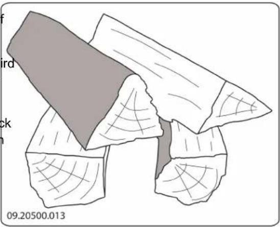
of Open stacking
The Sense 4.9 kW can be filled with a maximum 1 kg wood every 45 minutes.
The Sense 7 kW can be filled with a maximum 1.5 kg wood every 45 minutes.
The Sense 9 kW can be filled with a maximum of 1.9 kg wood every 45 minutes.
Do not fill the combustion chamber more that one third full, and never fill with wood above the openings for secondary air.
The Sense 300/400 has an indication line on the back wall. The wood fuel must remain below this indication line. See next figure.
natural_image
Illustration of a textured, irregularly shaped object with no visible text or symbols
natural_image
Technical line drawing of a mechanical device with open door and four legs (no text or symbols)If the logs are stacked openly, the wood will burn quickly as the oxygen can reach each log easily. If you want to use the stove for a short while, make an open stack.
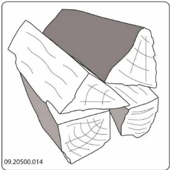
Compact stacking
natural_image
Illustration of a fragmented, irregularly shaped rock or mineral fragment with visible grain patterns (no text or symbols)Burning wood
After you have followed the instructions for lighting: If the logs are stacked tightly, the wood will burn more slowly as the oxygen can only reach some logs easily. If you want to burn wood for a longer period, make a compact stack.

-
Close the door of the appliance.
-
Close the primary air inlet and leave the secondary air inlet open.

Do not fill the appliance by more than a third.
The back wall has permanent vents (3) below the baffle plate that allow for post-combustion.
Advice

Never burn wood with an open door.

Regularly burn wood with intense roaring fires.
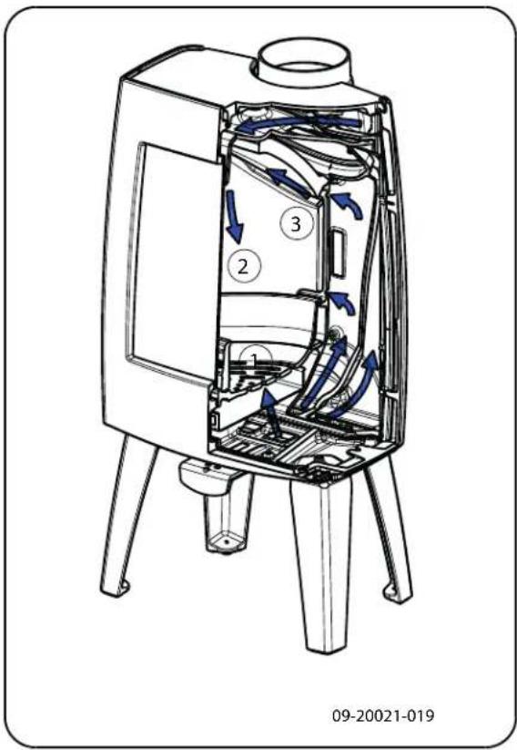
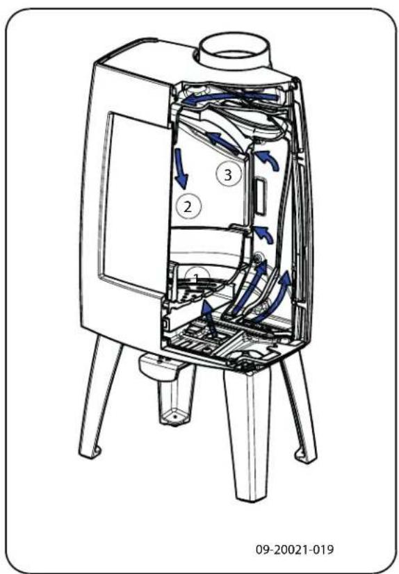
Controlling combustion air
The appliance has various features for air control; see next figure.
The appliance has one air slide that regulates both the primary air and the secondary air inlet. If the air slide is completely pulled out, the primary and the secondary air inlet is open. As the air slide is pushed in, the primary air inlet and then the secondary air inlet is closed. If the air slide is completely closed, a small air vent remains open to allow for the post-combustion under the baffle plate.
text_image
09-20021-019If you burn at a low setting frequently, tar and creosote may be deposited in the flue. Tar and creosote are highly combustible substances.
Thicker layers of these substances may catch fire if the temperature in the flue increases suddenly. By allowing the fire to burn very intensely regularly, layers of tar and creosote will disappear.
Low intensity fires can also cause tar deposits on the stove window and door.
When the outside temperature is mild, it is better to burn wood intensely for a few hours instead of having a low intensity fire for a long period of time.
▶ Control the air supply using the air vent.

The air inlet not only supplies air to the fire but to the glass as well, so that it does not quickly become dirty.
▶ Open the primary air inlet for the time being if the air supply by the secondary air inlet is inadequate or if you want to fan the fire.
▶ Topping up with a few logs regularly is better than adding many logs in one go.
Extinguishing the fire
Do not add fuel and just let the fire go out. If a fire is damped down by reducing the air supply, harmful substances will be released. For this reason, the fire should be allowed to go out naturally. Keep an eye on the fire until it has gone out. All air inlets can be closed once the fire has died completely.
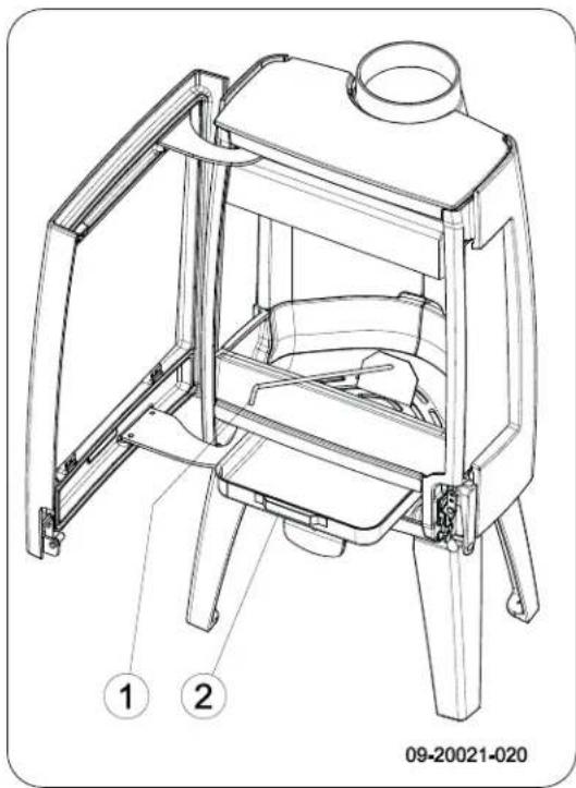
Removing ash
The primary air inlet regulates the air under the (1).
The secondary air inlet regulates the air for the (air wash) (2).
After wood has been burnt, a relatively small amount of ash remains. This ash bed is a good insulating layer for the stove base plate and improves combustion. It is a good idea to leave a thin layer of ash on the stove base plate.

The flow of air through the fire plate must not be obstructed, however, and no ash may be allowed to accumulate behind a cast-iron inner plate. Remove the excess ash regularly.
text_image
09-20021-020- Open the door of the appliance.
- Use the scraper supplied to sweep the excess into the ash pan.
- Using the glove supplied, remove the ash pan empty it.
- Replace the ash pan and close the door of the appliance.
Fog and mist
Fog and mist hinder the flow of flue gases through the fire-resistant inner plates are consumables that flue. Smoke can blow back and cause a stench. If airrissubject to wear and tear. Vermiculite inner plates not strictly necessary, it is better not to use the store fragile. Do not knock the inner plates with logs. in foggy and misty weather. Check the fire-resistant inner plates frequently and
Resolving problems
Refer to the appendix "Diagnostic diagram" to resolve any problems in using the appliance.
Maintenance
Follow the maintenance instructions in this chapter to keep the appliance in good condition.
Flue
In many countries, you are required by law to have your chimney checked and maintained.
At the start of the heating season: have the chimney swept by a recognised chimney sweep.
During the heating season and after the chimney has not been used for a long time: have the chimney checked for soot.
At the end of the heating season: close off the chimney and plug with newspaper.
Cleaning and other regularly maintenance

Do not clean the appliance when it is still warm.
Clean the exterior of the appliance with a dry lint-free cloth.
You can clean the appliance interior thoroughly at the end of the heating season:
ash If necessary, first remove the fire-resistant inner plates. See the chapter "Installation" for instructions on removing and installing the inner plates.
If necessary, clean the air supply ducts.
Remove the baffle plate at the top of the appliance and clean it.
Checking fire-resistant inner plates
The fire-resistant inner plates are consumables that are subject to wear and tear. Vermiculite inner plates are fragile. Do not knock the inner plates with logs.
Check the fire-resistant inner plates frequently and replace them when necessary.
See the chapter "Installation" for instructions on removing and installing the inner plates.
i
The insulating vermiculite or chamotte inner plates may develop hairline cracks, but this does not affect their performance adversely.
kettle directly onto an enamelled stove; use a stand to prevent damage.
i
Cast-iron inner plates last a long time if you remove frequently the ash that can accumulate behind them. If accumulated ash behind the cast-iron plate is not removed, the plate will longer be able to dissipate the heat to the s roundings and this may cause the plate to w or crack.
Lubrication
Although cast-iron is slightly self-lubricating, you will still need to lubricate moving parts frequently.
!
Never use the appliance without the fire-resistant inner plates.
no ur- arp Lubricate the moving parts (such as guide sys- tems,hinge pins, latches and air slides) with heat resistant grease that is available in the specialist trade.
Cleaning the glass
Touching up damaged paint
Small areas of damaged paint finish can be touched-up with a spray can of special heat-resistant paint, available from your supplier.
Dirt clings less easily to well-cleaned glass. Proceed as follows:
- Remove dust and loose soot with a dry cloth.
- Clean the glass with stove glass cleaner:
a. Apply stove glass cleaner to a kitchen sponge rub down the entire glass surface and give t cleaning agent time to react.
b. Remove the dirt with a moist cloth or kitchen tissue.
- Clean the glass again with a normal glass clean product.
- Rub the glass clean with a dry cloth or kitchen sue.
Do not use abrasive or aggressive products to clean the glass.
▶ Wear household gloves to protect your hands.
!
If the glass in the appliance is broken or cracked, it must be replaced before you can use appliance again.
!
Ensure that no stove glass cleaner runs between the glass and the cast-iron door.
Enamelled stove maintenance
Touching up the enamelled surface
Enamelling is a process carried out by traditional methods, meaning that it is possible that small colour differences and damage may occur. The appliances undergo a visual inspection in the factory, that is to say, the inspector looks at the surface for a period of 10 seconds from a distance of 1 metre.
Any damage that does not stand out is regarded as OK. A special heat-resistant paint is supplied with the appliance to touch up any minor damage caused during transport.
Apply the heat-resistant paint in thin layers and leave to dry well before using the appliance.
Some enamel colours are temperature-sensitive. It can happen that the colour changes during use. The original colour will return after the appliance has cooled down.
If enamelled surfaces become very hot, hairline cracks can occur. This is a normal phenomenon and has no impact on the functioning of the stove.
!
Ensure that the stove is not overburdened. If it does become overburdened then the surface gets very hot possibly resulting in lasting damage to the enamel.
Never clean the appliance while it is still hot. The most effective way to clean the enamelled surface of
the stove is with a mild green soap and lukewarm water. Use as little water as possible, rub the surface dry and prevent the formation of rust. Wire wool or other abrasives should never be used. Never place a
Checking the seal
Check whether the door sealing rope is still in good condition and works well. The sealing rope is subject to wear and will need to be replaced over time.

▶ Check the appliance for air leaks. Close any chinks with stove sealant.
In order to replace the side glass, all the inner panels and the air guide must first be removed. The air guide is attached with a M8 nut in the middle at the top of the

Allow the sealant to harden fully before lighting appliance. Proceed as follows:
the appliance, as any moisture in the sealant will form bubbles, resulting in a new air leak.
- Unscrew the two glass fixings with parts (1) and (2) and remove the glass (3), see following figure.
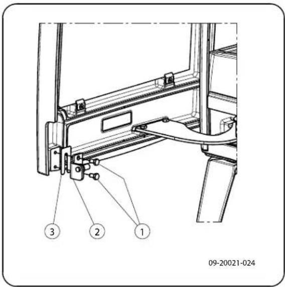
Adjust door closing
- Check the glass seal and, if necessary, fit a new clos-sealing rope.
Check if the door closes properly. If required, the closing of the door can be set looser or tighter by adjusting the distance between the locking cam and the door. Place the new glass in the grove and tighten the glass fixings. Proceed as follows:
- Open the door. The locking cam (2) is now freely accessible; see next figure.
- Unscrew the two screws (1) with which the locking cam is attached.
- By removing the packing plate (3) behind the locking cam (2), the door closes more tightly. If the door closes too tightly then insert an additional packing plate behind the locking cam.
- Tighten the two screws and check the closing of the door once again.
text_image
09-20021-024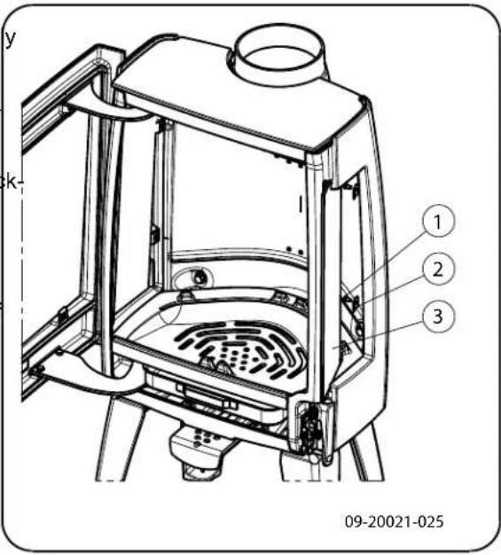
text_image
y k- 1 2 3 09-20021-025Replacing the glass

If the glass in the appliance is broken or cracked, it must be replaced before the stove is used again.

Sense spare parts
text_image
09-20021-01307 03.77548.000 side inner plate right 1 rear
08 03.77547.000 side inner plate left 1 rear
09 03.76188.000 baffle plate inner 1 plate
10 03.77550.000 side inner plate right 1
11 03.77549.002 side inner plate left 1
12 03.05216.000 ash pan 1
Sense 100/103/200/203
Pos. Part number Description Quantity
01 03.66544.002 base plate 1
02 03.77429.002 fire basket right rear 1
03 03.77428.000 fire basket left rear 1
04 03.77425.002 fire basket right 1
05 03.77424.002 fire basket left 1
06 03.77423.002 fire basket 1
07 03.77523.000 side inner plate right 1 rear
08 03.77522.000 side inner plate left 1 rear
09 03.76181.000 baffle plate inner 1 plate
10 03.77525.000 side inner plate right 1
11 03.77524.002 side inner plate left 1
12 03.05216.000 ash pan 1
Sense 300/303/400/403
Pos. Part number Description Quantity
01 03.66549.002 stove base 1
02 03.77444.002 fire basket right rear 1
03 03.77443.000 fire basket left rear 1
04 03.77442.002 fire basket right 1
05 03.77441.002 fire basket left 1
06 03.77440.002 fire basket 1

Appendix 1: Technical data
| Model | Sense100/103/200/203 | Sense100/103/200/203 | Sense300/303/400/403 |
| Nominal output 4.9 kW 7.0 kW | 9.0 kW | ||
| Flue connection (diameter) 150 | mm 150 mm 150 mm | ||
| Weight 105 kg - 125 kg 105 | kg - 125 kg 150 kg - | 180 kg | |
| Recommended fuel Wood | Wood | Wood | |
| Fuel property, max. length | 33 cm | 33 cm | 40 cm |
| Mass flow of flue gasses | 4.5 g/s | 5.1 g/s | 7.3 g/s |
| Flue gas temperature measured in the measurement section | 247 °C | 274 °C | 274 °C |
| Temperature measured at appliance exit | 317 °C | 351 °C | 352 °C |
| Minimum draught | 12 Pa | 12 Pa | 12 Pa |
| CO emission (13% _2 ) | 0.18 % | 0.07 % | 0.08 % |
| NOx emission (13% _2 ) | 81 mg/Nm ^3 | 89 mg/Nm ^3 | 75 mg/Nm ^3 |
| CnHm emission (13% _2 ) | 173 mg/Nm ^3 | 76 mg/Nm ^3 | 69 mg/Nm ^3 |
| Particulate emission | 27 mg/Nm ^3 | 25 mg/Nm ^3 | 19 mg/Nm ^3 |
| Particulate emission in accordance with NS3058-NS3059 | 2.87 g/kg | 2.87 g/kg | 4.7 g/kg |
| Efficiency | 79.5% | 80 % | 80 % |
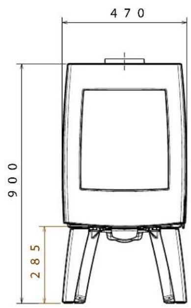
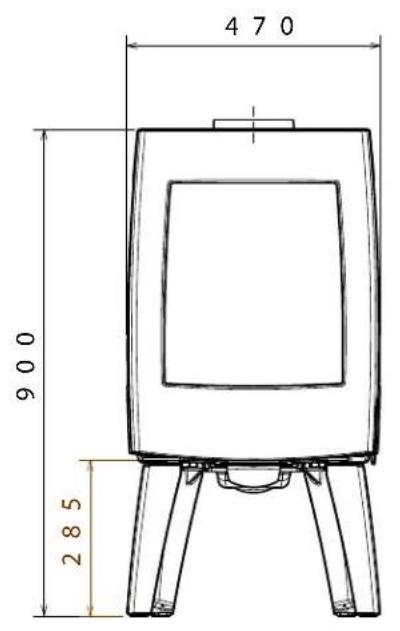
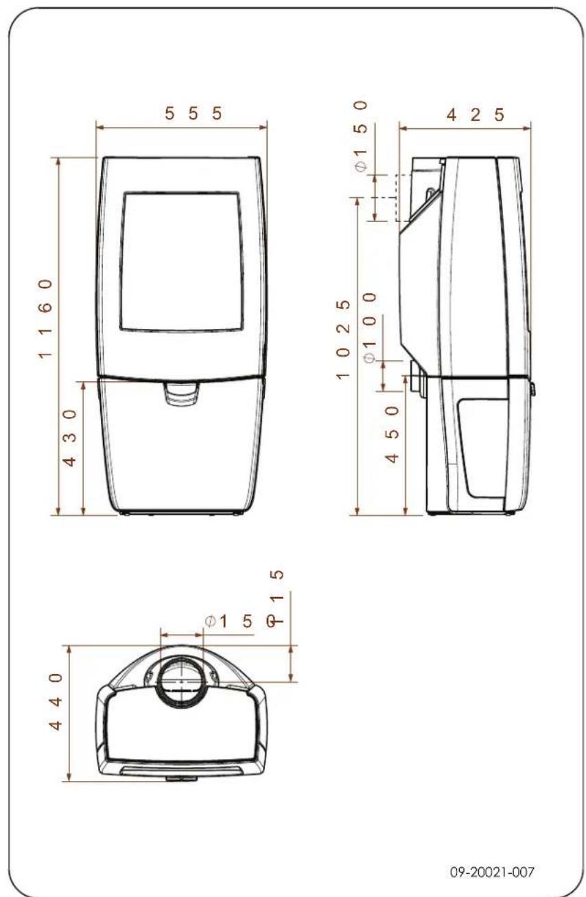
Appendix 2: Dimensions
Sense 100
text_image
470 900 285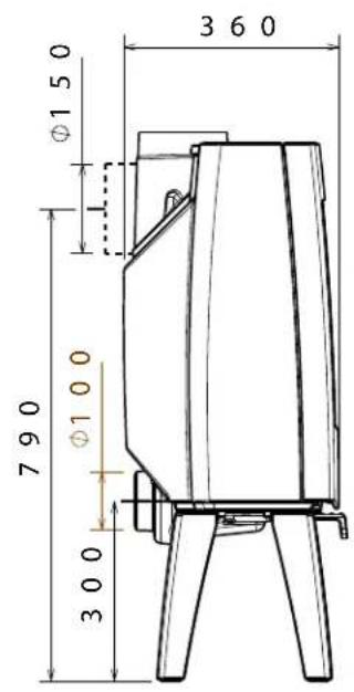
text_image
3 6 0 Ø1 5 0 7 9 0 Ø1 0 0 3 0 0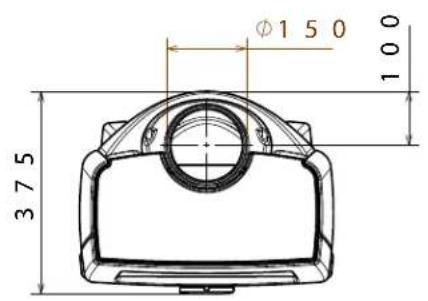
text_image
Ø1 50 375 10009-20021-001
Sense 103
text_image
470 900 285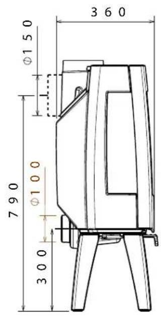
text_image
360 Ø150 Ø100 790 300
text_image
Ø1 50 375 10009-20021-002
Sense 200
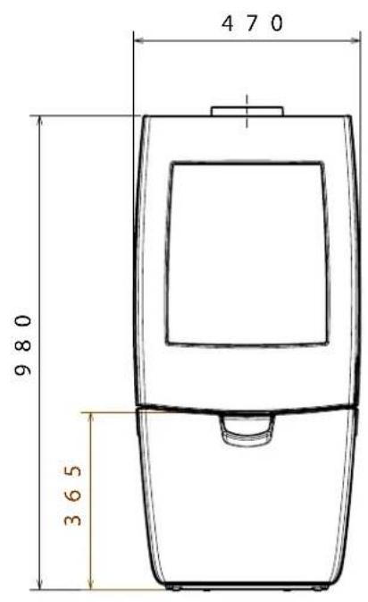
text_image
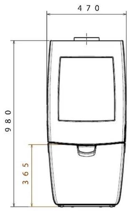
470 980 365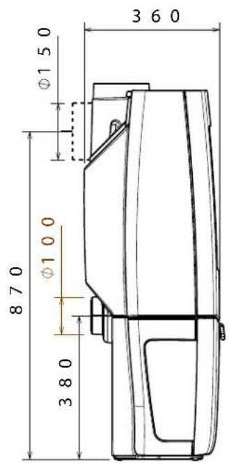
text_image
360 Ø150 Ø100 870 380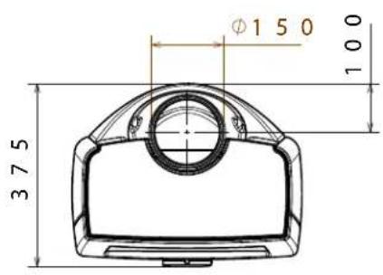
text_image
Ø1 5 0 37 5 1 0 009-20021-003
Sense 203
text_image
470 980 365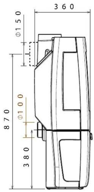
text_image
360 Ø150 Ø100 870 Ø100 380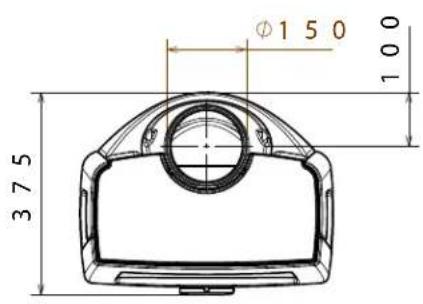
text_image
Ø1 5 0 3 7 5 1 0 009-20021-004
text_image
5 5 5 10 10 29 0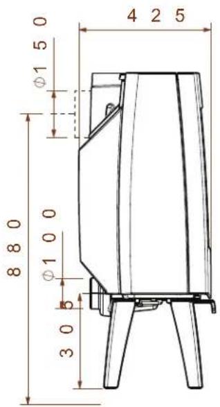
text_image
4 2 5 0 1 5 Ø1 8 8 0 1 0 0 Ø 3 0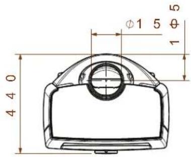
text_image
4 4 0 φ1 5 θ 1 509-20021-005
Sense 303
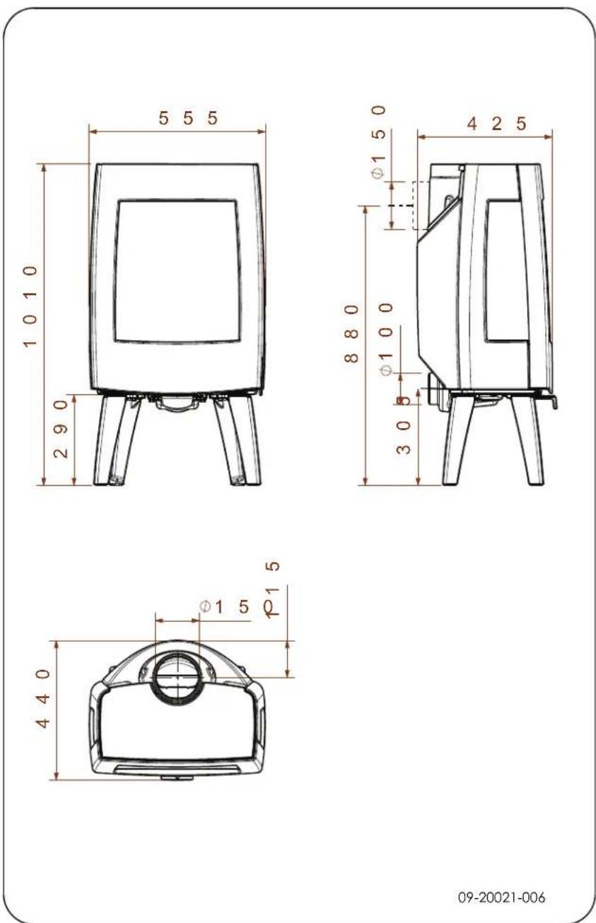
09-20021-006
09-20021-007
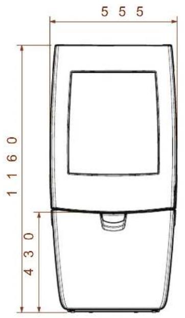
Sense 403
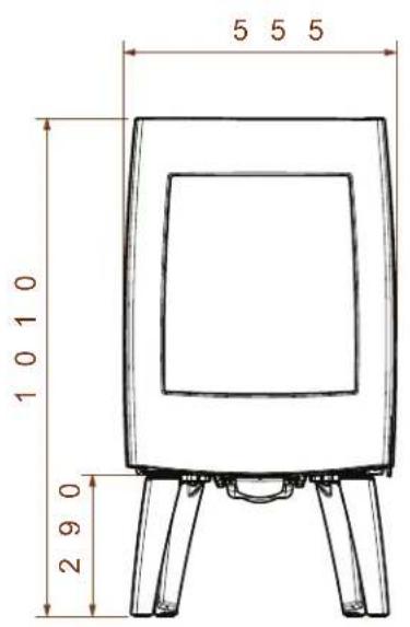
text_image
5 5 5 1 1 6 0 4 3 0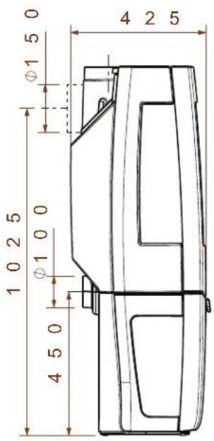
text_image
4 2 5 10 2 5 Ø1 5 0 Ø1 0 0 Ø1 0 0 4 5 0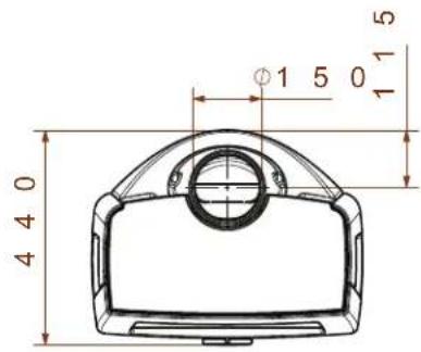
text_image
4 4 0 Ø1 5 0 1 1 509-20021-008
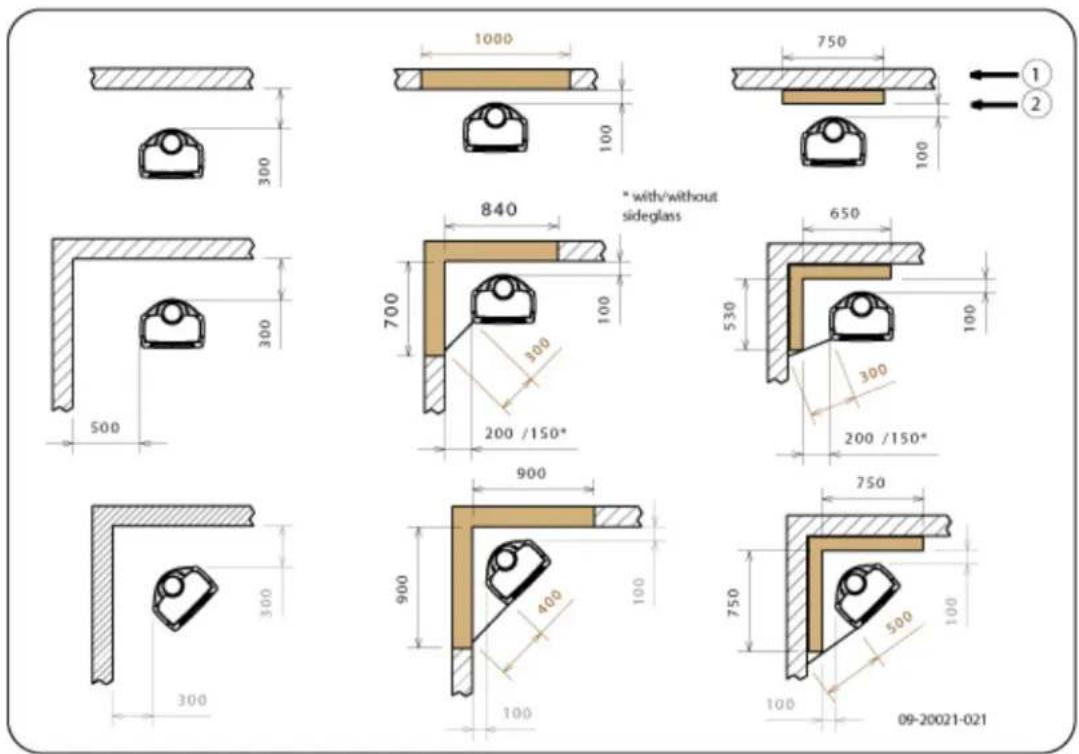
Appendix 3: Distance from combustible material
Sense 100/103/200/203 4.9 kW - 7 kW - Minimum distances in millim for version without heat shield
text_image
1000 750 1000 300 840 * with/without sideglass 650 700 100 530 300 200 /150* 900 750 900 400 100 300 100 750 500 100 100 300 500 09-20021-021| 1 Combustible material |
| 2 Incombustible material, thickness 100 mm |

Please note: In order to guarantee the supply of combustion air when there is no outside air supply connection, the distance from the connection collar for the outside air to the wall must be at least 20 mm. If required, the connection collar can be removed.
Sense 100/103/200/203 4.9 kW - 7 kW - Minimum distances in millim for version with heat shield
text_image
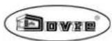
1000 20 750 20 1 2 * with/without sideglass 630 20 650 475 20 300 200 /150* 900 300 300 300 900 400 100 750 500 100 100 100 09-20021-022| 1 Combustible material |
| 2 Incombustible material, thickness 100 mm |

Please note: In order to guarantee the supply of combustion air when there is no outside air supply connection, the distance from the connection collar for the outside air to the wall must be at least 20 mm. If required, the connection collar can be removed.

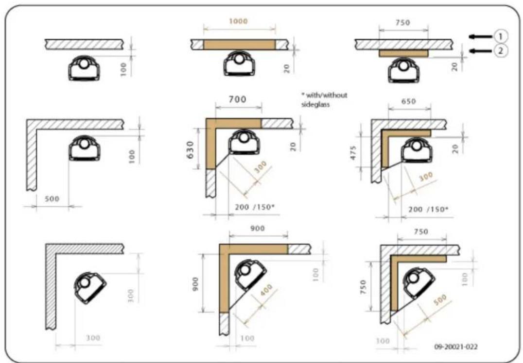
Sense 300/303/400/403 - 9 kW - Minimum distances in millimetres for sion without heat shield
09-20021-031
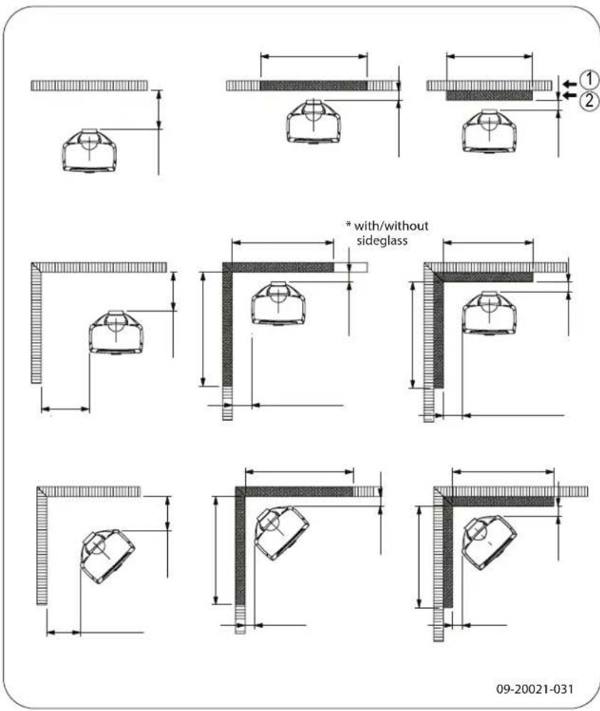
Sense 300/303/400/403 - 9 kW - Minimum distances in millimetres for sion with heat shield
text_image
* with/without sideglass 09-20021-032Sense - Dimensions of fireproof floor plate
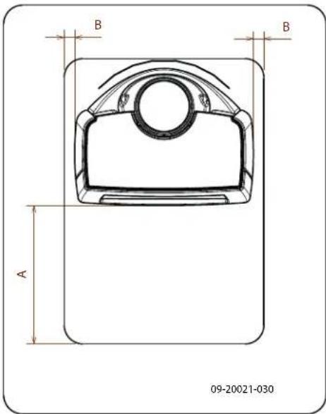
text_image
B B A 09-20021-030Minimum dimensions of fireproof floor plate
| A (mm) | B (mm) | |
| Din 18891 500 300 | ||
| Germany 500 300 | ||
| Finland 400 100 | ||
| Norway 300 5 |
Appendix 4: Diagnosis diagram
| Problem | ||||||
| ● | Wood will not stay lit | |||||
| ● | Gives off insufficient heat | |||||
| ● | Smoke emissions into the room when adding wood | |||||
| ● | Fire in appliance is too intense, is hard to adjust | |||||
| ● | Deposit on the glass | |||||
| possible cause possible | solution | |||||
| ● | ● | ● | ● | Insufficient draught | A cold flue usually failsto create sufficient draught. Follow the instructions for starting a fire in the 'Use' section; open a window. | |
| ● | ● | ● | ● | Wood too damp Use wood with no more than 20% moisture. | ||
| ● | ● | ● | ● | Logs too large | Use small pieces of kindling. Use split logs no larger than 30 cm in circumference. | |
| ● | ● | ● | ● | ● | Wood stacked incorrectly | Stack the logs in a way that allows adequate air flow between the logs (open stacking, see "Burning wood") |
| ● | ● | ● | ● | Flue does not work properly | Check whether the chimney meets the requirements: at least 4 metres high, correct diameter, well-insulated, smooth inside, not too many bends, no obstructions in chimney (bird'snest, too much soot deposit), hermetically tight (no chinks). | |
| ● | ● | ● | ● | Chimney stack incorrect Sufficiently high above the roof, no obstacles in the vicinity | ||
| ● | ● | ● | ● | ● | Air inlets set incorrectly Open the air | inlets completely. |
| ● | ● | ● | ● | Appliance connected to the flue incorrectly | Connection should be hermetically tight. | |
| ● | ● | ● | ● | Vacuum in area in which the appliance is installed | Switch off extraction systems. | |
| ● | ● | ● | ● | Insufficient supply of fresh air | Provide an adequate air supply; if necessary use outside air connection. | |
| ● | ● | ● | ● | Bad weather? Inversion (reversed air flow in chimney) we recommend you don't use the appliance in the case of inversion because of a high outside temperature if required, installan extra hood on the flue to increase the draught extreme wind speeds | ||
| ● | Draught in the living room | Avoid draught in the living room, do not place the appliance near a door or heating air ducts. | ||||
| ● | Flames touch the glass | Make sure the wood is not positioned too close to the glass. Slide the primary air inlet cover closer to the "Closed" position. | ||||
| ● | Appliance is leaking air Check the door seals and appliance joints. | |||||
Index
A
Adding wood
smoking stove.38....
Adverse weather conditions, do not burn wood 20
Aerating the fire.19....
Air combustion control 19
Air control.19....
Air inlets 17
Air leak.21....
ash 19
Ash pan
open 20
Ashes
remove 19
B
Bearing capacity of floor 11
Burning 18
adding fuel 18
appliance is hard to adjust.... 38
fire is too intense.... 38
insufficient heat.... 38
topping up fuel 19
Burning wood
insufficient heat 20
C
Cap on the flue.... 11
Carpet 11
Cast iron inner plates 13
Chinks in appliance.... 21
Cleaning
appliance 20
glass 21
Combustible material
distance from 33
Connecting
dimensions 25
Connecting outside air supply.... 15
Connection collar for connection to chimney 14-15
Connection to chimney
at the rear 15
at the top.... 14
rear 15
top 14
Controlling air supply 19
Creosote 19
D
Damage .13....
Damp wood 16
Dimensions 25
Door
adjust 22
closing 22
Locking cam
packing plate 22
opening .13....
sealing rope 21
Draught 24
Drying wood 16
E
Efficiency 5, 7, 9, 24
maintenance 21
External air supply
connecting to 16
Extinguishing the fire.... 19
F
Fan 11
connecting outside air supply 15
rule of thumb.... 11
Fan louvre 11
Filling level of the appliance.... 19
Finishing coat, maintenance 21
Fire
extinguishing 19
kindle
Lighting 16
Fire-resistant inner plates
maintenance 20
remove 13
Fire safety
distance from combustible material.... 33
floor 11
furniture 11
walls 11

Fireproof inner plates
warning 16
fitting .14....
Fitting
heat shield 14
Floors
bearing capacity.1.1....
fire safety 11
Flue
connecting to 16....
connection diameter.24......
height 11
maintenance 20....
requirements 11
Flue cap..11....
Flue gas
temperature .5, .7, .9, .24
Flue gasses
mass flow.... 24
Fog, do not burn wood 20
Fuel
adding 19
necessary amount.... 20
suitable 16
topping up.... 19
unsuitable 16
wood 16
G
Glass
cleaning 21
cracked 22
deposit 38
replacing 22
Glass damaged 22
H
Heat shield 14
Heat, insufficient.... 20, 38
Hinge
adjust .22......
|
Inner plate
vermiculite 13
Inner plates, fire-resistant
remove 13
Installing
dimensions 25
K
Kindling 38
L
Lighting fire 16
Lubricant 21
Lubricate 21
M
Maintenance
Clean appliance.... 20
cleaning the glass 21
emai 21
Fire-resistant inner plates 20
flue 20
lubrication 21
sealing 21
Mist, do not burn wood 20
N
Nominal output 20, 24
0
Open
ash pan.20....
Opening
door 13
Outside air supply 11, 15
P
Paint
Smoke
during first use 16
Particulate emission.... 24
Parts, removable 13
Preventing chimney fire.... 19
Primary air inlet 17
R
Removable parts 13
Remove
fire-resistant inner plates 13
Removing ash.... 19
Replacing
glass 22
s
Screens
deposit .38......
Sealing rope for door.21.
Secondary air inlet.17.
Smoke emissions into the room 10
Smoking appliance.38
Softwood .16
Solving problems.20,.38....
Stacking logs 18
Storing wood.... 16
Stove glass cleaner 21
Suitable fuel.... 16
Sweeping flue 20
T
Tar 19
Temperature 24
Topping up with fuel 19
U
Unsuitable fuel 16
V
Vermiculite
fire-resistant 13
Vermiculite inner plates 13
W
Walls
fire safety....11
Warning
chimney fire.... 16, 19
chimney fires 10
fireproof inner plates.... 16
flammable materials 10
glass broken or cracked.... 10, 21-22
hot surface 10
requirements 10
stove glass cleaner 21
terms and conditions for insurance..... 10
ventilation 10-11
Weight 24
Wood 16
damp 16
drying 16
right sort 16
storing 16
will not stay lit 38
Table des matières
Introduction 3
text_image
Technical diagram of a portable stove with numbered parts labeled 1 to 509-20021-009

text_image
① ② ③ ④ ⑤ 09-20021-010natural_image
Line drawing of a vintage portable TV stand with four legs and a top handle (no text or symbols)natural_image
Technical line drawing of a mechanical component with a labeled tool (1), no readable text or symbols present.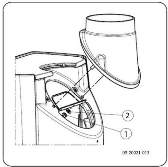
text_image
09-20021-015 ① ②natural_image
Illustration of layered geological strata with no visible text or symbolsnatural_image
Technical line drawing of a mechanical device with open door and four legs (no text or symbols)
natural_image
Illustration of a rolled-up stone or parchment with visible grain patterns (no text or symbols)natural_image
Illustration of a broken stone or mineral sample with visible grain patterns and texture (no text or symbols)09.20500.014
text_image
09-20021-019natural_image
Technical line drawing of a portable stove or oven unit with labeled components (no text or symbols beyond labels)natural_image
Line drawing of a vintage portable TV stand with four legs and a top cover, no text or symbols presentnatural_image
Illustration of layered geological strata with no visible text or symbolsnatural_image
Technical line drawing of a mechanical device with open door and four legs (no text or symbols)
Heizen mit Holz
natural_image
Illustration of a textured, folded object with layered surfaces (no text or symbols)natural_image
Illustration of a broken stone or mineral sample with visible grain patterns and texture (no text or symbols)09.20500.014

text_image
09-20021-019natural_image
Technical line drawing of a portable stove or oven unit with labeled components (no text or symbols beyond labels)text_image
Technical diagram of a portable stove with numbered parts labeled 1 to 509-20021-009
text_image
Technical diagram of a device with numbered parts labeled 1 to 509-20021-010
2. Puerta

natural_image
Line drawing of a portable electronic device with four legs and a top handle, no text or symbols presentnatural_image
Technical line drawing of a mechanical component with a labeled tool (1), no readable text or symbols present.natural_image
Technical line drawing of a mechanical assembly with two views: top shows four legs and three legs with mounting holes, bottom shows a transparent container with a labeled part (no text or symbols on the diagram itself)natural_image
Illustration of layered geological strata with no visible text or symbolsnatural_image
Line drawing of a mechanical device with open door and four legs (no text or symbols)09.20021.033
Alimentar con leña
natural_image
Illustration of a broken stone or mineral sample with visible grain patterns (no text or symbols)
natural_image
Illustration of fragmented stone or mineral fragments with visible patterns and no text or symbolsnatural_image
Line drawing of a portable electronic device with four legs and a top handle, no text or symbols present.natural_image
Technical line drawing of a mechanical component with a labeled part (1), no readable text or symbols present.natural_image
Illustration of layered geological strata with a central drop symbol (no text or labels)natural_image
Line drawing of a simple chair or table with four legs and a small cylindrical object inserted (no text or symbols)A

B

C

09-20021-018
C:
natural_image
Line drawing of a mechanical device with open door and four legs (no text or symbols)09.20021.033
natural_image
Illustration of a broken stone or metal structure with visible grain patterns (no text or symbols)natural_image
Illustration of fragmented stone or mineral fragments with visible grain patterns (no text or symbols)natural_image
Technical line drawing of a portable stove or oven unit with labeled components (no text or symbols beyond labels)natural_image
Line drawing of a portable electronic device with four legs and a top handle, labeled '09-20021-012' at bottom (no other text or symbols)natural_image
Technical line drawing of a mechanical component with a labeled tool (1), no readable text or symbols present.Montere varmeskjold
natural_image
Illustration of layered geological strata with no visible text or symbolsnatural_image
Line drawing of a four-legged stool with a handle and mounting feet (no text or symbols)A

B

C

09-20021-018
C:

natural_image
Line drawing of a mechanical device with open door and four legs (no text or symbols)09.20021.033
Sense 4,9 kW har en maksimal fylling på 1 kg ved per 45 minutter.
▶ Sense 7 kW har en maksimal fylling på 1,5 kg per 45 minutter.
Sense 9 kW har en maksimal fylling på 1,9 kg per 45 minutter.
natural_image
Illustration of a textured, irregularly shaped object with grid patterns (no text or symbols)
Ved løst ilegg forbrenner veden raskt fordi det lettere kommer oksygen til hver treski. Bruk løst ilegg hvis du skal fyre en kort stund.
Kompakt ilegg
natural_image
Illustration of fragmented stone or mineral fragments with visible grain patterns (no text or symbols)text_image
Technical diagram of a mechanical assembly with numbered components labeled 1, 2, and 309-20021-024
Skifte glass

Deler, demonterbare 12
Demonterbare deler 12