5070 - Frying Pan COLEMAN - Free user manual and instructions
Find the device manual for free 5070 COLEMAN in PDF.



| Brand | Coleman |
| Model | 5070 |
| Product Type | Forced Air Construction Heater |
| Fuel | Propane (vapor only) |
| Heat Output | 40,000 BTU/h |
| Fuel Consumption | 1.7 L/h (0.44 gal US/h) |
| Regulator Outlet Pressure | 70 kPa (10 psi) |
| Hose Length | 3 m (10 ft) |
| Hot Air Flow | 4.2 m³/min (150 ft³/min) |
| Motor | 3000 rpm, 115 V, 60 Hz, 1.1 A |
| Ignition | Manual Piezo |
| Operating Temperature Range | -23 °C to 29.4 °C (-10 °F to 85 °F) |
| Weight | 6.4 kg (14 lb) |
| Dimensions (H × W × D) | 35.6 × 21.6 × 41.9 cm (14 × 8.5 × 16.5 in) |
| Required Ventilation | Fresh air opening of at least 0.3 m² (3 ft²) |
| Safety Distances to Combustibles | Sides/rear: 0.6 m (2 ft), top: 1.2 m (4 ft) |
| Minimum Distance to Electrical Outlet | 1.8 m (6 ft) |
| Minimum Distance to Propane Cylinders | 1.8 m (6 ft) |
| Propeller Maintenance | Every 500 hours or as needed |
| Electrode Maintenance | Cleaning and gap adjustment (0.5-0.6 cm) every 500 hours |
| Warranty | 1 year limited |
Frequently Asked Questions - 5070 COLEMAN
User questions about 5070 COLEMAN
0 question about this device. Answer the ones you know or ask your own.
Ask a new question about this device
Download the instructions for your Frying Pan in PDF format for free! Find your manual 5070 - COLEMAN and take your electronic device back in hand. On this page are published all the documents necessary for the use of your device. 5070 by COLEMAN.
USER MANUAL 5070 COLEMAN
PROPANE FORCED-AIR HEATERS
INSTRUCTIONS FOR USE
IMPORTANT
Read this manual carefully before assembling, using or servicing this heater. Keep this manual for future reference. If you have questions about assembly, operation, servicing or repair of this heater, please call Coleman at 1-800-835-3278 or TDD: 316-832-8707. In Canada call 1 800 387-6161.
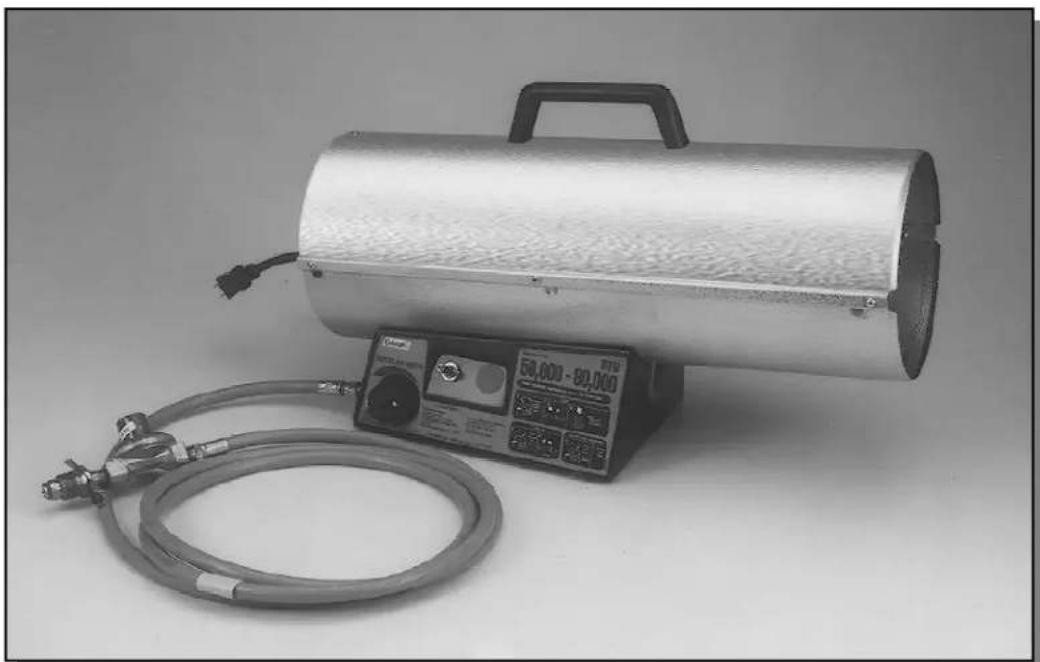
Models: 5070 and 5075 Series
This product is designed and approved for use as an indoor construction heater in accordance with ANSI and CSA standards. It is intended for temporary heating of unoccupied buildings under construction, alteration or repair. It is not intended for home or recreational use.


This manual contains important information about the assembly, operation and maintenance of this construction heater. General safety information is presented in these first few pages and is also located throughout the manual. Particular attention should be paid to information accompanied by the safety alert symbol "▲WARNING".
Keep this manual for future reference and to educate new users of this product. This manual should be read in conjunction with the labeling on the product.
GENERAL HAZARD WARNING:
FAILURE TO COMPLY WITH THE PRECAUTIONS AND INSTRUCTIONS PROVIDED WITH THIS HEATER CAN RESULT IN DEATH, SERIOUS BODILY INJURY AND PROPERTY LOSS OR DAMAGE FROM HAZARDS OF FIRE, EXPLOSION, BURN, ASPHYXIATION, CARBON MONOXIDE POISONING, AND/OR ELECTRICAL SHOCK.
ONLY PERSONS WHO CAN UNDERSTAND AND FOLLOW THE INSTRUCTIONS SHOULD USE OR SERVICE THIS HEATER.
IF YOU NEED ASSISTANCE OR HEATER INFORMATION SUCH AS AN INSTRUCTION MANUAL, LABELS, ETC., CONTACT THE MANUFACTURER.
WARNING: FIRE, BURN, INHALATION, AND EXPLOSION HAZARD. KEEP SOLID COMBUSTIBLES, SUCH AS BUILDING MATERIALS, PAPER OR CARDBOARD, A SAFE DISTANCE AWAY FROM THE HEATER AS RECOMMENDED BY THE INSTRUCTIONS. NEVER USE THE HEATER IN SPACES WHICH DO OR MAY CONTAIN VOLATILE OR AIRBORNE COMBUSTIBLES, OR PRODUCTS SUCH AS GASOLINE, SOLVENTS, PAINT THINNER, DUST PARTICLES OR UNKNOWN CHEMICALS.
WARNING
NOT FOR HOME OR RECREATIONAL VEHICLE USE.
This product is designed and approved for use as an indoor construction heater in accordance with standard ANSI Z83.7 - CSA 2.14 - (2000).
We cannot foresee every use which may be made of our heaters. Check with your local fire safety authority if you have questions about heater use.
Other standards govern the use of fuel gases and heat producing products for specific uses. Your local authorities can advise you about these.
This indoor construction heater should not be used in areas directly exposed to water spray, rain, and/or dripping water.
CARBON MONOXIDE POISONING:
This construction heater is a combustion appliance. All combustion appliances produce carbon monoxide (CO) during the combustion process. This product is designed to produce extremely minute, non-hazardous amounts of CO if used and maintained in accordance with all warnings and instructions. Do not block air flow into or out of the heater.
Early signs of carbon monoxide poisoning may resemble the flu with headaches, dizziness and/or nausea. If these symptoms are present during operation of this product get fresh air immediately!
Safety Information continues on next page
MAKE SURE ADEQUATE VENTILATION IS PROVIDED. Provide a fresh outside air opening at least three (3) square feet (0.3m^2) or its equivalent, i.e., 1^× 3^(0.3m x 0.9m) for each heating unit. DO NOT USE THIS HEATER IN LIVING QUARTERS OR WHILE SLEEPING! California lists carbon monoxide as a reproductive toxin under Proposition 65.
PROPANE GAS:
This product is fueled by propane gas. Propane gas is invisible, odorless, and flammable. An odorant is normally added to help detect leaks and can be described as a "rotten egg" smell. The odorant can fade over time so leaking gas is not always detectable by smell alone.
Propane gas is heavier than air and leaking propane will sink to the lowest level possible. It can be ignited by ignition sources including matches, lighters, sparks or open flames of any kind many feet away from the original leak. Use only propane gas set up for vapor withdrawal.
Propane gas should be stored and used in compliance with local ordinances and codes or with ANSI/NFPA 58. Turn off propane when not in use.
FIRE/EXPLOSION:
During operation, this product can be a source of ignition. Keep heater area clear and free from combustible materials, gasoline, paint thinner, cleaning solvents and other flammable vapors and liquids. Do not use heater in areas with high dust content.
MINIMUM HEATER CLEARANCES FROM COMBUSTIBLE MATERIALS: TWO (2) FEET (0.6M) FROM SIDES AND REAR, FOUR (4) FEET (1.2M) FROM TOP, AND SIX (6) FEET (1.8) FROM THE OUTLET. Keep heater at least six (6) feet (1.8m) away from propane tanks and keep propane hoses away from outlet opening of the heater.
ADDITIONAL SAFETY INFORMATION:
- Never alter or modify heater, propane hose/regulator assembly or propane cylinders. Do not attach duct work of any kind to this heater.
- Always inspect heater, propane hoses and propane cylinders before use. Do not use if leaking propane or if damaged. Replace hoses that have excessive wear, abrasion or cuts. Use only Coleman repair parts and Coleman propane hoses and regulator assemblies.
- KEEP OUT OF REACH OF CHILDREN.
- Heater will remain hot up to thirty (30) minutes after being turned off.
- Operate heater only on level, stable surface.
- Use only the electrical voltage and frequency specified on product decal.
- Electrical grounding instructions — this heater is equipped with a three-prong (grounding) plug for your protection against shock hazard and should be plugged directly into a properly grounded three-prong receptacle.
- Use only a three-prong, grounded extension cord.
- Make sure heater is plugged into outlet before igniting heater.
- Keep the appliance area clear and free from combustible materials, gasoline and other flammable vapors and liquids.
- Do not block or obstruct the flow of combustion and ventilation air.
- Blower (forced air) and radiant type heaters must not be directed toward any propane-gas container within 20 feet (6m)
CONTENTS
SECTION_PAGE
General Safety Information 2,3
Product Identification 4
Unpacking 5
Theory of Operation 5
Propane Supply 5,6
Ventilation 6
Preparation 6,7
Operation 7-9
Storage 9
Maintenance 9, 10
Troubleshooting 11
Preventative Maintenance Schedule. 11
Service Procedures 12, 13
Specifications 13
Wiring Diagram 14
Replacement Parts 14
Warranty 43
Technical and Repair Service 44
PRODUCT IDENTIFICATION
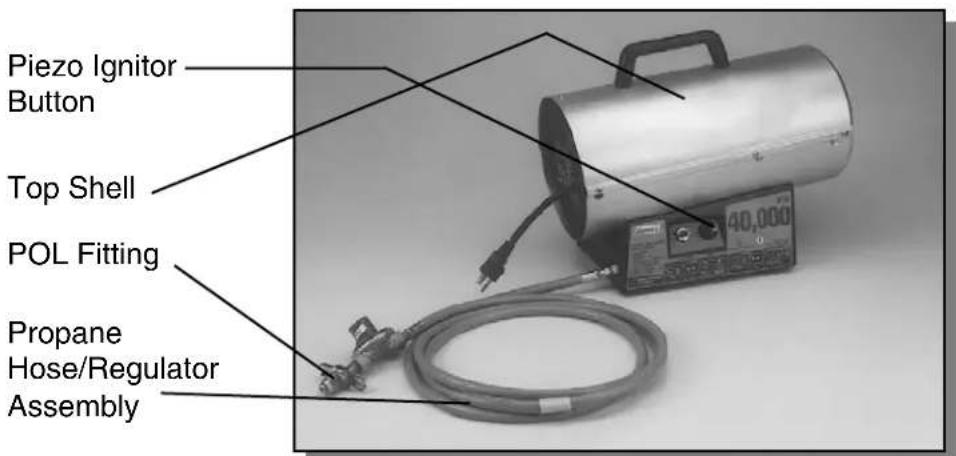
Figure 1 - 40,000 BTU/Hr. Model
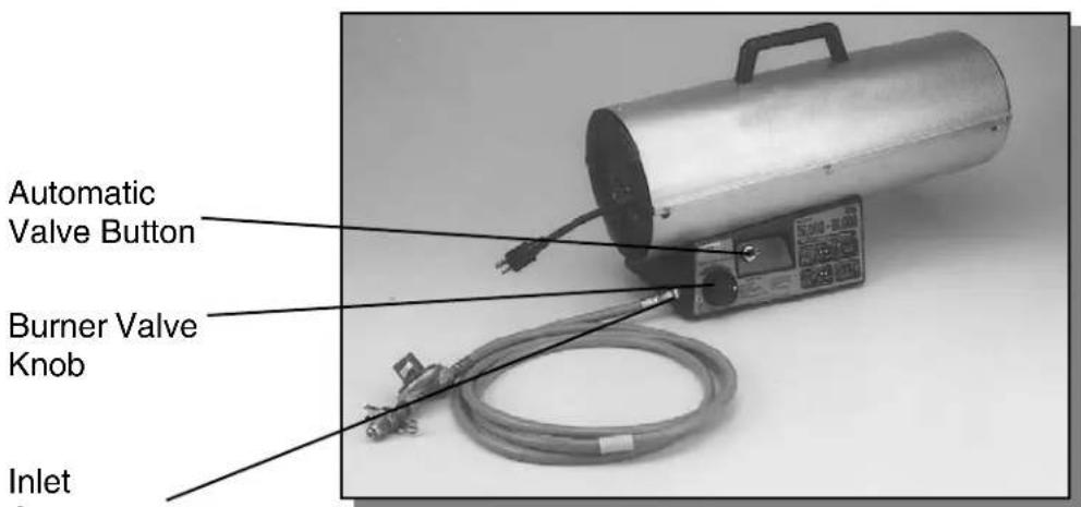
Figure 2 - 50,000 to 80,000 BTU/Hr. Model
- Remove all packing items applied to heater for shipment. Keep plastic cover caps (attached to inlet connection and hose/regulator assembly) for storage.
- Remove all items from carton.
- Check all items for shipping damage. If heater is damaged, promptly inform dealer where you bought heater.
The Fuel System: The hose/regulator assembly attaches to the propane gas supply. The propane gas moves through the thermoelectric valve and out the nozzle.
The Air System: The motor turns the fan. The fan pushes air into and around the combustion chamber. This air is heated and provides a stream of clean, hot air.
The Ignition System: The piezo spark ignitor (Model 5070A) or Electronic Module (Model 5075A) sends voltage to the electrode. The spark at the electrode ignites the fuel air mixture.
The Safety Control System: This system causes the heater to shut down if the heater overheats for any reason including loss of electric power. (The fan will continue to operate if electric power is not lost.)
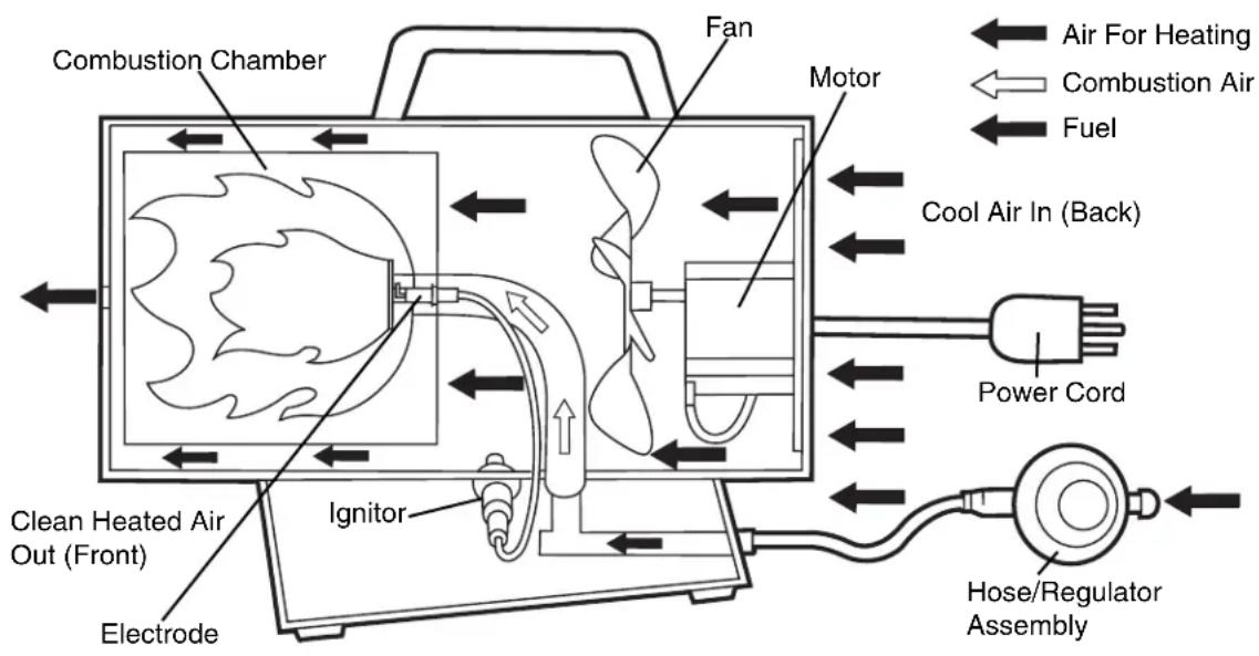
Cross Section Operational View (5070A Model Shown)
Propane gas and propane tank(s) are to be furnished by the user.
Use this heater only with a propane vapor withdrawal supply system. See Chapter 5 of the Standard for Storage and Handling of Liquefied Petroleum Gas, ANSI/NFPA 58. Your local library or fire department will have this booklet.
The amount of propane gas ready for use from propane tanks varies. Two factors decide this amount:
- The amount of propane gas in tank(s).
- The temperature of tank(s)
Propane Supply Information continues on next page
UNPACKING
THEORY OF OPERATION
PROPANE SUPPLY Continued
The chart below shows the minimum number of 20-pound or larger tanks needed to run these heaters at the temperature indicated for at least 10 hours. Do not operate them with tanks smaller than indicated. Reduced performance will result.
NUMBER OF TANKS REQUIRED
Average Temperature (^)
At Tank Location 32^ 20^ 10^ 0^ - 10^
$$ (0 ^ {\circ} \mathbf {C}) (- 7 ^ {\circ} \mathbf {C}) (- 1 2 ^ {\circ} \mathbf {C}) (- 1 8 ^ {\circ} \mathbf {C}) (- 2 3 ^ {\circ} \mathbf {C}) $$
5070A751 (40,000 BTU/Hr.) 1-20# 1-40# 1-100# 2-100# 3-100#
5075A751 (80,000 BTU/Hr.) 1-100# 2-100# 2-100# 3-100# 3-100#
Less gas is vaporized at lower temperatures. You may need two or more 100-pound tanks or one larger tank in colder weather. Your local propane gas dealer will help you select the proper supply system.
VENTILATION
WARNING
Provide at least a 3-square-foot (0.3m^2) opening of fresh, outside air while running heater. If proper outside air ventilation is not provided, carbon monoxide poisoning can occur. Provide proper outside air ventilation before running heater.
PREPARATION
WARNING
Test all gas piping and connections for leaks after preparation or servicing. Never use an open flame to check for a leak. Apply a mixture of liquid soap and water to all joints. Bubbles forming show a leak. Correct all leaks before using product.
- Determine propane supply needed. (See Propane Supply).
- Connect hose to inlet connector. Tighten firmly in clockwise direction using 9/16 wrench.
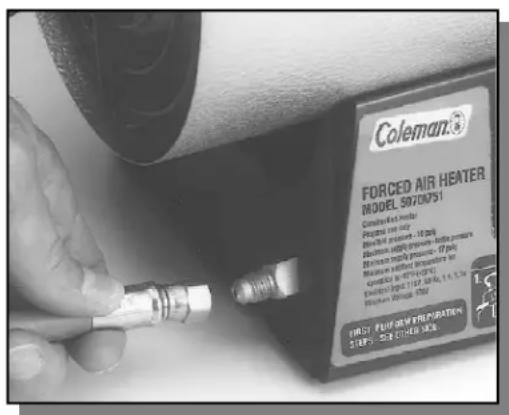
Hose and Inlet Connector
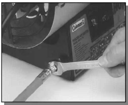
Tighten with Wrench
Continued
- Connect POL fitting on hose/regulator assembly to propane tank(s). Turn POL fitting counterclockwise into threads on tank. Tighten firmly.
IMPORTANT: Tighten regulator with vent pointing down. Pointing vent down protects regulator from weather damage.
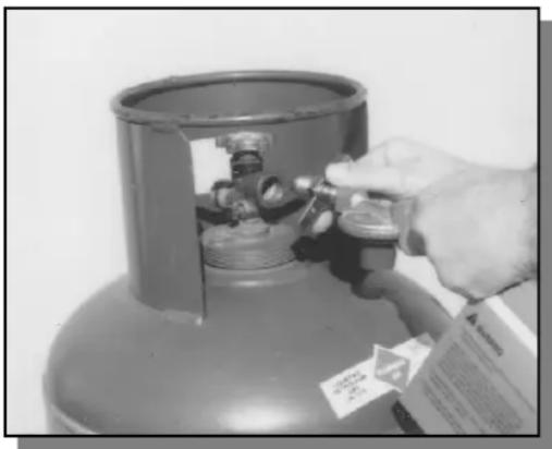
Regulator With Vent Pointing Down
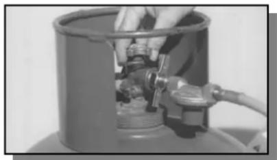
- Open valve on propane tank(s) slowly. Note: If not opened slowly, excess-flow check valve on propane tank will stop gas flow. If this happens, close propane valve and open again slowly.
- Check all connections for leaks. Apply mixture of liquid soap and water to gas joints. Bubbles forming show a leak that must be corrected before using heater.
- Close propane supply valve.
WARNING
Review and understand the warnings in the General Safety Information Section. They are needed to safely operate this heater. Follow all local ordinances or codes when using this heater.
To Start Heater
- Follow all preparation, ventilation, and safety information.
- Locate heater on stable and level surface. Make sure strong drafts do not blow into front or rear of heater. Do not use in areas directly exposed to water spray, rain, and/or dripping water.
- Open valve on propane tank(s) slowly. Note: If not opened slowly, excess-flow check valve on propane tank will stop gas flow. If this happens, close propane valve and open again slowly.
- Plug power cord of heater into a three-prong, grounded extension cord. Extension cord must be at least six feet long. Extension cord must be UL listed.
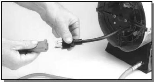
Extension Cord Size Requirement
Up to 50 feet (15m) long, use 18 AWG rated cord. 51 to 100 feet (30m) long, use 16 AWG rated cord. 101 to 200(61m) feet long, use 14 AWG rated cord
- Plug extension cord into a 120 volt/60 hertz, three-hole, grounded outlet. The motor will start, turning the fan forcing air through the heater.
- To light:
Model 5070A
Push in and hold automatic valve button. Push ignitor (Red) button. You may need to push the ignitor button 3-8 times until heater lights. Note: Hose may be filled with air. If so, keep automatic valve button pressed and wait 20 seconds before pressing ignitor again. When heater lights, keep automatic valve button pushed in. Release button after 30 seconds.
Model 5075A
Push in & hold automatic valve button. NOTE: Hose may be filled with air. If so, continue to keep automatic valve button pressed. When heater lights, keep automatic valve button pushed in. Release button after 30 seconds.
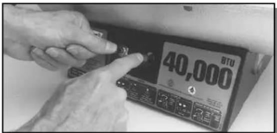
5070A751 Model Shown
- If heater goes out, repeat step 6.
- Adjust burner valve to desired heat level. (5075A751 Model only)
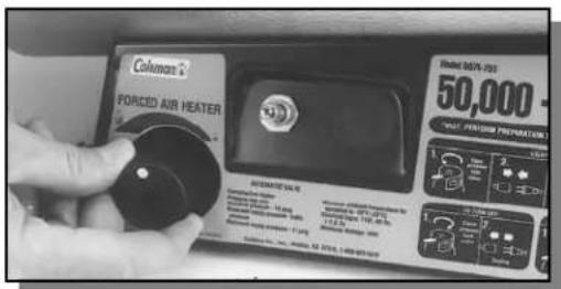
Continued
To Stop Heater
- Tightly close valve on propane tank(s).
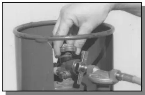
OPERATION Continued
- Wait a few seconds. Heater will burn gas left in hose.
- Unplug heater.
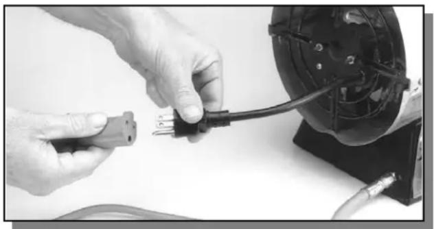
WARNING
Disconnect heater from propane supply tank(s) before storage.
- Store propane tank(s) in safe manner. See Chapter 5 of Standard for Storage and Handling of Liquefied Petroleum Gases, ANSI/NFPA 58. Follow all local codes.
- Place plastic cover caps over brass fittings on inlet connection and hose/regulator assembly of heater.
- Store heater in a dry, clean, and safe place.
WARNING
Never attempt to service heater while it is plugged in, connected to propane supply, operating or hot. Severe burns and electrical shock can occur.
- Keep heater clean. Clean heater annually or as needed to remove dust and debris. If heater is dirty or dusty, clean heater with a damp cloth.
- Inspect heater before each use. Check connections for leaks. Apply mixture of liquid soap and water to connections. Bubbles forming show a leak. Correct all leaks before using heater.
- Inspect propane hose/regulator assembly before each use. Replace hoses that have excessive wear, abrasion, or cuts. Inspect "O" ring for damage. Replace if cut or cracked.
- Have heater inspected yearly by a qualified service person.
- Keep inside of heater free from combustible and foreign objects.
STORAGE
MAINTENANCE
Continued
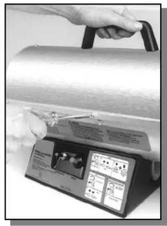
- FAN - Clean every 500 hours of operation or as needed.
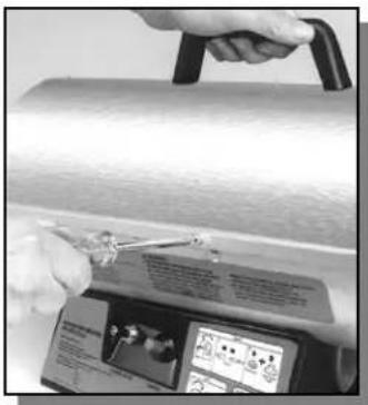
A. Remove screws along each side of heater and on top of the motor guard using a Phillips screwdriver. These screws attach top and lower shells together.
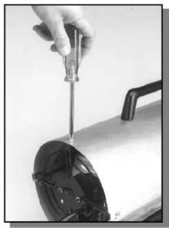
B. Lift top shell off.
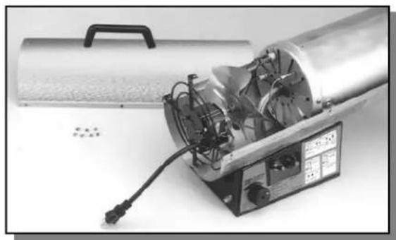
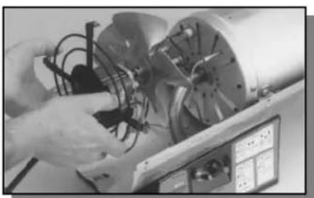
C. Lift out motor/guard assembly.
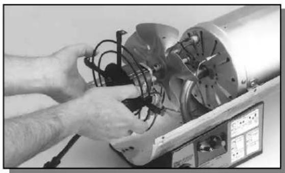
IMPORTANT: Do not allow the motor/guard assembly to rest on the fan or damage may be caused to the blades.
D. Clean fan using soft cloth moistened with kerosene or solvent. Dry fan thoroughly. Clean inside the shell adjacent to where the fan runs.
E. Replace motor/guard assembly and top shell.
7. ELECTRODE
A. Make sure gap between electrode wire and burner nozzle is .20 (0.5 cm) to .25" (0.6 cm). Access electrode from inside combustion chamber. No other maintenance is needed for electrode. Continued
WARNING
Never attempt to service heater while it is plugged in, connected to propane supply, operating or hot. Severe burns and electrical shock can occur.
SYMPTOM POSSIBLE CAUSE REMEDY
Fan does not turn No electrical power to heater Check voltage to electrical outlet. when heater is If voltage is good, check heater plugged in. power cord for breaks.
Fan blades bent Replace fan. See Replacing Fan,
Page 13.
Defective motor Replace motor. See Replacing Motor,
page 12.
Heater will not User did not follow prepara- Repeat preparation and operation. Ignite. tion or operation instruc-tion instructions. See Preparation,
tions properly
pages 6 & 7 and Operation, pages 7,
8 & 9.
No spark at electrode. To test for spark, follow step 9 under Replacing Electrode, page 13. If you see spark at ignitor, have heater serviced by qualified service person. If no spark seen:
A) Loose or disconnected ignitor wire
B) Wrong spark gap
C) Piezo ignitor loose
D) Bad electrode
E) Bad piezo ignitor
F) Bad electronic module
High surrounding air temperature causing thermal limit device to shut down heater.
Restricted air flow
Damaged fan
Excessive dust or debris in surrounding area
A) Check ignitor wire. Tighten or reattach loose ignitor wire. See page 5 for ignitor wire location.
B) Set gap between ignitor electrode and target plate to .20" (0.5 cm).
C) Tighten piezo ignitor to base of heater.
D) Replace electrode. See Replacing Electrode, page 13.
E) Replace ignitor.
F) Replace electronic module.
This can happen when running heater in temperatures above 85^ (29^) . Run heater in cooler temperatures.
Check heater inlet and outlet. Remove any obstructions.
Replace fan. See Replacing Fan, page 13.
Clean heater. See Maintenance, pages 9 & 10.
Heater shuts down while running.
AWARNING
Use only in areas free of high dust content.
HOW OFTEN
Clean every 500 hours of operation or as needed.
HOW TO
See Fan, page 10
Electrode
Clean and regap every 500 hours of operation or replace as needed.
See Electrode, page 10
TROUBLESHOOTING
Continued
PREVENTIVE MAINTENANCE SCHEDULE
WARNING
Never attempt to service heater while it is plugged in, connected to propane supply, operating, or hot. Severe burns and electrical shock can occur.
REPLACING MOTOR
- Remove top shell (see FAN under maintenance).
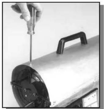
- Lift out motor/guard assembly.
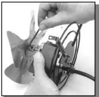
- Use a 1/8 hex wrench to loosen setscrew which holds fan to motor shaft.
-
Remove fan from motor shaft (it may be necessary to pry the fan from the shaft) being careful not to damage the blades.
-
Remove the ground wire screw and two wire leads from the motor.
-
Remove two nuts and two screws which attach the motor to the guard.
-
Discard motor.
-
Attach new motor to guard using two screws and nuts.
-
Replace fan on shaft with approx. 3 / 8'' (1 cm) of shaft showing through fan hub.
10.Tightensetscrewfirmly(40-50inchpounds).
- Install ground wire and wire leads to motor.
12.Set motor/guard assembly in the lower shell. Turn fan to check for interference.
13.Install the top shell.
Continued
REPLACING FAN
- Remove motor/guard assembly (follow steps 1 through 4 above).
- File the setscrew mark off the motor shaft.
- Replace fan (follow steps 9 through 13 above).
REPLACING ELECTRODE
- Remove shell and motor/guard assembly (see FAN under maintenance).
- Pull wire off of electrode.
- Remove screw holding electrode to diffuser.
- Remove electrode from diffuser.
- Place new electrode in diffuser.
- Install screw, insure electrode gap is .20 (0.5 cm) to .25 (0.6 cm) inch.
- Push ignitor wire on electrode wire.
- Reinstall motor/guard assembly and upper shell.
- For Model 5070A, push ignitor button and check for spark between deflector and electrode. For Model 5075A check for sparks between deflector & electrode after plugging in. Do not connect propane supply.
SERVICE PROCEDURES Continued
FORCED AIR HEATER SPECIFICATIONS 40,000 BTU/HR - MODEL 5070A
Input Rating (BTU/HR) 40,000
Fuel Propane Vapor Only
Fuel Consumption
Gallons/Hour .44 (1.7 L)
Pounds/Hour 1.8 (0.8kg)
Regulator Output Pressure 10 PSI (70 kPa)
Hose 10 Ft. (3m)
Hot Air Output (CFM Approx.) 150
Motor 3,000 RPM
Power Required 115 Volt/60 Hz
Amps 1.1
Ignition Manual/Piezo
Weight (pounds) 14 (6.4kg)
Size (HWL) (IN) 14 × 8.5 × 16.5
(35.6 x 21.6 x 41.9 cm)
Temperature Operating Range -10°F to 85°F
(-23^ to 29.4^)
FORCED AIR HEATER SPECIFICATIONS 50,000 TO 80,000 BTU/HR - MODEL 5075A
Input Rating (BTU/HR) 80,000 Max
Fuel Propane Vapor Only
Fuel Consumption
Gallons/Hour .9 (3.4 L)
Pounds/Hour 3.7 (1.7 kg)
Regulator Output Pressure 10 PSI (70 kPa)
Hose 10 Ft. (3m)
Hot Air Output (CFM Approx.) 300
Motor 3,000 RPM
Power Required 115 Volt/60 Hz
Amps 2.6
Ignition Electronic Module
Weight (pounds) 17 (7.7kg)
Size (HWL) (IN) 14 x 8.5 x 22.5
(35.6× 21.6× 57.2cm)
Temperature Operating Range -10°F to 85°F
(-23^ to 29.4^)
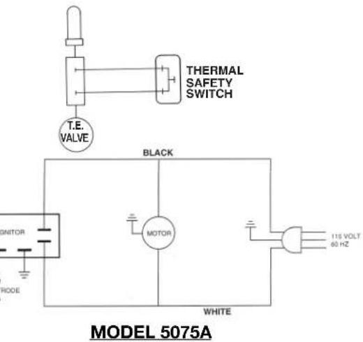
WIRING DIAGRAM
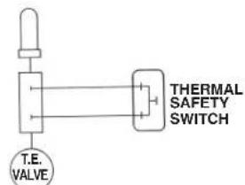
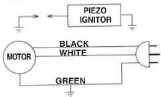
MODEL 5070A
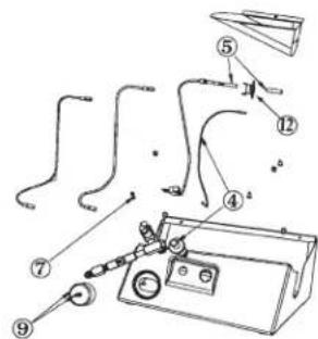
REPLACEMENT PARTS
WARNING
Use only original replacement parts. Do not substitute or use generic parts. Improper replacement parts could cause serious or fatal injuries.
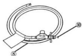
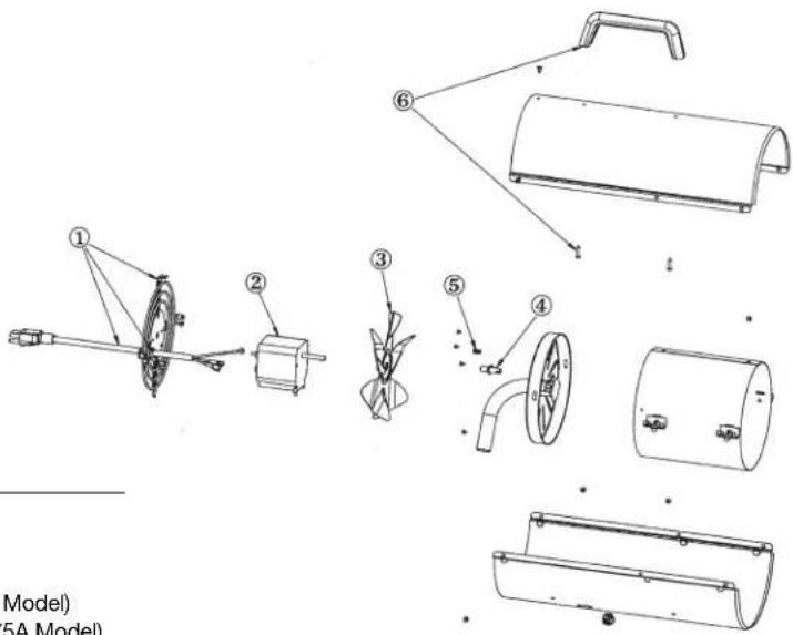
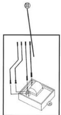
I.D. PART NO.DESCRIPTION NO.
1 5070-2851 Guard & Pigtail Assembly
2 5070-2801 Motor (5070A Model) 5075-2801 Motor (5075A Mod
3 5070-2891 Fan Blade for Heater (5070A Model)
5075-2891 Fan Blade for Heater (5075A Model)
4 5070-3111 Electronic Ignition Assembly (5070A Model)
5 5070-3271 Thermocouple & Clip 5075-3271 Thermocouple, Clip & Spacer
6 5070-2001 Handle & Screws
7 5070-2181 Gas Tip (5070A Model) 5075-2181 Gas Tip (5075A Model)
8 5080-5651 Hose & Regulator
9 5080-1491 Knob & Screw (5075A Model)
105410A1381O-ring
11 5075B3001 E.I. Module Assembly* (5075A Model)
12 5070A2701 Thermostat
- Used on heaters manufactured after August 2002.
CHAUFFERETTES À AIR PULSE, AU GAZ PROPANE
MODE D'EMPLOI
IMPORTANT
INCENDIE OU EXPLOSION:
CAUSE POSSIBLE SOLUTION
Libras/Hora 1.8 (0.8 kg)
Limited One Year Warranty
The Coleman Company, Inc. ("Coleman") warrants that for a period of one year from the date of original retail purchase, this product will be free from defects in material and workmanship. Coleman, at its option, will repair or replace this product or any component of the product found to be defective during the warranty period. Replacement will be made with a new or remanufactured product or component. If the product is no longer available, replacement may be made with a similar product of equal or greater value. This is your exclusive warranty.
This warranty is valid for the original retail purchaser from the date of initial retail purchase and is not transferable. Keep the original sales receipt. Proof of purchase is required to obtain warranty performance. Coleman dealers, service centers, or retail stores selling Coleman® products do not have the right to alter, modify or in any way change the terms and conditions of this warranty.
What This Warranty Does Not Cover
This warranty does not cover normal wear of parts, parts that are not genuine Coleman® parts, or damage resulting from any of the following: negligent use or misuse of the product; use on improper voltage or current; commercial use of the product; use contrary to the operating instructions; disassembly, repair or alteration by anyone other than Coleman or an authorized service center. Further, the warranty does not cover Acts of God, such as fire, flood, hurricanes and tornadoes. Warranty void if damage to product results from the use of a part other than a genuine Coleman® part.
COLEMAN SHALL NOT BE LIABLE FOR DEFECTS THAT ARE CAUSED BY THE USE OF UNAUTHORIZED PARTS OR SERVICE. COLEMAN SHALL NOT BE LIABLE FOR ANY INCIDENTAL OR CONSEQUENTIAL DAMAGES CAUSED BY THE BREACH OF ANY EXPRESS OR IMPLIED WARRANTY OR CONDITIONS. EXCEPT TO THE EXTENT PROHIBITED BY APPLICABLE LAW, ANY IMPLIED WARRANTY OF MERCHANTABILITY OR FITNESS FOR A PARTICULAR PURPOSE IS LIMITED IN DURATION TO THE DURATION OF THE ABOVE WARRANTY OR CONDITIONS. SOME STATES, PROVINCES, OR JURISDICTIONS DO NOT ALLOW THE EXCLUSION OR LIMITATION OF INCIDENTAL OR CONSEQUENTIAL DAMAGES OR LIMITATIONS ON HOW LONG AN IMPLIED WARRANTY LASTS, SO THE ABOVE LIMITATIONS OR EXCLUSION MAY NOT APPLY TO YOU. THIS WARRANTY GIVES YOU SPECIFIC LEGAL RIGHTS, AND YOU MAY ALSO HAVE OTHER RIGHTS THAT VARY FROM STATE TO STATE OR PROVINCE.
How to Obtain Warranty Service
Take the product to an authorized Coleman service center. You can find the nearest authorized Coleman service center by visiting www.coleman.com or calling 1-800-835-3278 or TDD 316-832-8707 in the United States or 1 800 387-6161 in Canada. If a service center is not conveniently located, attach to the product a tag that includes your name, address, daytime telephone number and description of the problem. Include a copy of the original sales receipt. Carefully package the product and send either by courier or insured mail with shipping and insurance prepaid to:
For products purchased in the United States:
The Coleman Company, Inc.
3600 North Hydraulic
Wichita, KS 67219
For products purchased in Canada:
Sunbeam Corporation (Canada) Limited
DBA Jarden Consumer Solutions
5975 Falbourne Street
Mississauga, Ontario
Canada L5R 3V8
The costs of transporting the product to Coleman or an authorized service center for warranty service is the responsibility of the purchaser.
Do not mail products with fuel in tanks, or with disposable propane cylinders. Remove glass globes from lanterns and wrap separately.
DO NOT RETURN THIS PRODUCT TO THE
PLACE OF PURCHASE
If you have any questions regarding this warranty please call 1-800-835-3278 or TDD 316-832-8707 in the United States or 1-800 387-6161 in Canada.
The Coleman Company, Inc.
3600 North Hydraulic
Wichita, KS 67219
Sunbeam Corporation (Canada) Limited
DBA Jarden Consumer Solutions
5975 Falbourne Street
The Coleman Company, Inc.
3600 North Hydraulic
Wichita, KS 67219
Sunbeam Corporation (Canada) Limited
DBA Jarden Consumer Solutions
5975 Falboume Street
Mississauga, Ontario
Canada L5R 3V8
© 2006 The Coleman Company, Inc. All rights reserved. Coleman® and are registered trademarks of The Coleman Company, Inc.
Coleman
The Coleman Company, Inc.
3600 N. Hydraulic
Wichita, KS 67219 U.S.A.
1-800-835-3278
TDD: 316-832-8707
Sunbeam Corporation (Canada) Limited
DBA Jarden Consumer Solutions
5975 Falbourne Street
Mississauga, Ontario
CANADA L5R 3V8
1800387-6161
- PROPANE FORCED-AIR HEATERS
- INSTRUCTIONS FOR USE
- IMPORTANT
- Models: 5070 and 5075 Series
- GENERAL HAZARD WARNING:
- WARNING
- NOT FOR HOME OR RECREATIONAL VEHICLE USE.
- CARBON MONOXIDE POISONING:
- PROPANE GAS:
- FIRE/EXPLOSION:
- ADDITIONAL SAFETY INFORMATION:
- CONTENTS
- SECTION_PAGE
- PRODUCT IDENTIFICATION
- NUMBER OF TANKS REQUIRED
- VENTILATION
- PREPARATION
- To Start Heater
- Extension Cord Size Requirement
- Model 5070A
- Model 5075A
- To Stop Heater
- Disconnect heater from propane supply tank(s) before storage.
- Never attempt to service heater while it is plugged in, connected to propane supply, operating or hot. Severe burns and electrical shock can occur.
- ELECTRODE
- SYMPTOM POSSIBLE CAUSE REMEDY
- AWARNING
- HOW OFTEN
- HOW TO
- REPLACING MOTOR
- REPLACING FAN
- REPLACING ELECTRODE
- FORCED AIR HEATER SPECIFICATIONS 40,000 BTU/HR - MODEL 5070A
- FORCED AIR HEATER SPECIFICATIONS 50,000 TO 80,000 BTU/HR - MODEL 5075A
- CHAUFFERETTES À AIR PULSE, AU GAZ PROPANE
- INCENDIE OU EXPLOSION:
- CAUSE POSSIBLE SOLUTION
- Limited One Year Warranty
- What This Warranty Does Not Cover
- How to Obtain Warranty Service
- For products purchased in the United States:
- For products purchased in Canada:
Brand : COLEMAN
Model : 5070
Category : Frying Pan