BHD51 - Drill BERNER - Free user manual and instructions
Find the device manual for free BHD51 BERNER in PDF.

| Brand | Berner |
| Model | BHD51 |
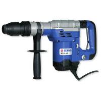
| Product Type | Professional Rotary Hammer |
| Rated Voltage | 230 V |
| Input Power | 1300 W |
| Impact Energy | 2-14 J |
| Concrete Drilling Capacity (Drill Bits) | 12-45 mm |
| Tool Holder | SDS Max® |
| Chisel Positions | 18 |
| Weight | 6.9 kg |
| Sound Pressure Level LPA | 93 dB(A) (uncertainty 3 dB) |
| Sound Power Level LWA | 104 dB(A) (uncertainty 3 dB) |
| Vibration Emission Value (Concrete Drilling) | 9.1 m/s² (uncertainty 1.6 m/s²) |
| Vibration Emission Value (Chiseling) | 7.4 m/s² (uncertainty 1.6 m/s²) |
| Double Insulation | Yes (conforms to EN 60745) |
| Torque Limiting Clutch | Yes, adjustable 40 Nm / 80 Nm |
| Electronic Speed Control | Yes |
| Soft Start Function | Yes |
| Vibration-Damped Handle | Yes |
| Service Indicator Lights | Yellow (brush wear) and red (fault) |
| Package Contents | Drill, side handle, carrying case, instruction manual, exploded view |
| Warranty | 12 months |
| After-Sales Service | Berner authorized service centers |
Frequently Asked Questions - BHD51 BERNER
User questions about BHD51 BERNER
0 question about this device. Answer the ones you know or ask your own.
Ask a new question about this device
Download the instructions for your Drill in PDF format for free! Find your manual BHD51 - BERNER and take your electronic device back in hand. On this page are published all the documents necessary for the use of your device. BHD51 by BERNER.
USER MANUAL BHD51 BERNER
Instruction manual (M)
BOHRHAMMER BHD-5-1 und 8-1
Article Number:
107381, 91950, 91951
Languages:
nl, en, fr, de, it
Bedienungsanleitung/Sicherheitshinweise
Instruction Manual/Safety instructions
Notice d'Utilisation/Indications de sécurité
Instrucciones de manejo/Instrucciones de segundar
Manual de instruções/Instruções de segança
Manuale d'Istruzioni/Indicazioni per la sicurezza
Gebruiksaanwijzing/Veiligheidsinstrukties
Brugsanvising/Sikkerhedsinstruktioner
Bruksanvising/Säkerhetsinstruktioner
Bruksanvising/Sikkerhetsforskrifter
Käyttohjfe/Turvallisuusohjeet
Exyeipio Odyiw/Odyiec aqpaalia
Kullanim Kilavuzu/Güvenlik talimatari
Instrukcja obslugi/Instrukcje dotyczace bezpieczentwa
Návod k obsslze/BezpecnostníPokyny
Hasznalatiutasitas/Biztonsagi elóirások
Причунк/Cурнона уутста
Prirucnik s uputama/Sigurnosne upute
Instrukcjirokasgramata /drosibas noradijumi
PykoobocnoTo no ekcnnyataun/Prabnila texnkn 6e3onacnoctn
Masinos eksploatavimo vadovas/Saugumo instructcija
Návod na obsluhu/BezpecnostnéPokyny
BERNER
BHD 5-1, BHD 8-1
D SDS MAX KOMBINATIONSHAMMER
GB SDS MAX COMBINATION HAMMERS
F MARTEAUX COMBINÉS SDS MAX
E MARTILLOS DE COMBINACION SDS MAX
P COMBINACAO DE MARTELOS SDS MAX
1 MARTELLI COMBINATI SDS MAX
NL SDX MAX COMBIHAMERS
DK SDS MAX KOMBINATIONSHAMRE
SDS MAX KOMBINATIONSHAMMARE
N SDS MAX KOMBINASJONSHAMMERE
FI SDS MAX-KOMBIPORAVASARAT
EL ΣΦYPEΣ SYNΔYAEMOY SDS MAX
TR SDS MAX KOMBINE KIRICILAR
PL MLOTY KOMBINOWANE SDS MAX
CZ KOMBINOVANA KLADIVA SDS MAX
HU SDS MAX KOMBINALF FUROKALAPACSOK
SDS MAX KOMBINOVANE UDARNE BUSILICE
HR SDS MAX KOMBINIRANI CEKICI
LV SDS MAX KOMBINETE AMURI
RU SDS MAX KOMENHINPOBAHHbIE OTBOHbIE MOJOTK
LTSDS MAX KOMBINUOTIEJI SMUGINIAI GRAZTAI
SK KOMBINOVANE KLADIVÁ SDS MAX
English (original instructions) 16
Francais (traduction des instructions originales) 24
Chief Executive Chief Operations
Officer (CEO) Officer Berner (COO)


You have chosen a Berner tool. Years of experience, thorough product development and innovation make Berner one of the most reliable partners for professional power tool users.
Technical Data
| BHD 8-1 BHD 5-1 | |||
| Art. No | 91951 | 91950 | |
| Voltage | V | 230 | |
| Type | 1 | ||
| Power input W | 1500 | 1300 | |
| Impact energy J | 2-14 | 2-14 | |
| Total drilling range in concrete: | |||
| solid bits | mm | 12-48 | 12-45 |
| core bits | mm | 40-125 | 40-100 |
| Optimum drilling range in concrete: | ||
| solid bits | mm 25-45 | 25-35 |
| Chisel positions | 24 | 18 |
| Tool holder | SDS Max® | SDS Max® |
| Weight | kg 9.1 | 6.9 |
| L PA (sound pressure) dB(A) 95 | 93 | |
| K PA (sound pressure uncertainty) dB(A) 3 | 3 | |
| L WA (sound power) dB(A) 106 | 104 | |
| K WA (sound power uncertainty) dB(A) 4 | 3 | |
Vibration total values (triax vector sum) determined according to EN 60745:
| Vibration emission value ah | ||
| Drilling into concrete | ||
| ah,HD = | m/s27.8 | 9.1 |
| Uncertainty K = | m/s21.5 | 1.6 |
| Vibration emission value ah | ||
| Chiselling | ||
| ah,Cheq = | m/s27.2 | 7.4 |
| Uncertainty K = | m/s21.5 | 1.6 |
The vibration emission level given in this information sheet has been measured in accordance with a standardised test given in EN 60745 and may be used to compare one tool with another. It may be used for a preliminary assessment of exposure.

WARNING: The declared vibration emission level represents the main applications of the tool. However if the tool is used for different applications, with different accessories or poorly maintained, the vibration emission may differ. This may significantly increase the exposure level over the total working period.
An estimation of the level of exposure to vibration should also take into account the times when the tool is switched off or when it is running but not actually doing the job. This may significantly reduce the exposure level over the total working period.
Identify additional safety measures to protect the operator from the effects of vibration such as: maintain the tool and the accessories, keep the hands warm, organisation of work patterns.
| Fuses: | ||
| Europe | 230 V tools | 10 Amperes, mains |
| U.K. & Ireland | 230 V tools | 13 Amperes, in plugs |
Definitions: Safety Guidelines
The definitions below describe the level of severity for each signal word. Please read the manual and pay attention to these symbols.
DANGER: Indicates an imminently hazardous situation which, if not avoided, will result in death or serious injury.
WARNING: Indicates a potentially hazardous situation which, if not avoided, could result in death or serious injury.
CAUTION: Indicates a potentially hazardous situation which, if not avoided, may result in minor or moderate injury.
NOTICE: Indicates a practice not related to personal injury which, if not avoided, may result in property damage.
Denotes risk of electric shock.
Denotes risk of fire.
EC-Declaration of Conformity MACHINERY DIRECTIVE

BHD 5-1, BHD 8-1
Berner declares that these products described under "technical data" are in compliance with: 2006/42/EC, EN 60745-1, EN 60745-2-6.
These products also comply with Directive 2004/108/ EC. For more information, please contact Berner at the following address or refer to the back of the manual.
The undersigned is responsible for compilation of the technical file and makes this declaration on behalf of Berner.
Jörn Werner Ulrich Lindner
Chief Executive Chief Operations
Officer (CEO) Officer Berner (COO)


WARNING: To reduce the risk of injury, read the instruction manual.
General Power Tool SafetyWarnings

WARNING! Read all safety warnings and instructions. Failure to follow the warnings and instructions may result in electric shock, fire and/or serious injury.
SAVE ALL WARNING AND INSTRUCTIONS FOR FUTURE REFERENCE
The term "power tool" in the warnings refers to your mains-operated (corded) power tool or battery-operated (cordless) power tool.
1) WORK AREA SAFETY
a) Keep work area clean and well lit. Cluttered or dark areas invite accidents.
b) Do not operate power tools in explosive atmospheres, such as in the presence of flammable liquids, gases or dust. Power tools create sparks which may ignite the dust or fumes.
c) Keep children and bystanders away while operating a power tool. Distractions can cause you to lose control.
2) ELECTRICAL SAFETY
a) Power tool plugs must match the outlet. Never modify the plug in any way. Do not use any adapter plugs with earthed (grounded) power tools. Unmodified plugs and matching outlets will reduce risk of electric shock.
b) Avoid body contact with earthed or grounded surfaces such as pipes, radiators, ranges and refrigerators. There is an increased risk of electric shock if your body is earthed or grounded.
c) Do not expose power tools to rain or wet conditions. Water entering a power tool will increase the risk of electric shock.
d) Do not abuse the cord. Never use the cord for carrying, pulling or unplugging the power tool. Keep cord away from heat, oil, sharp edges or moving parts. Damaged or entangled cords increase the risk of electric shock.
e) When operating a power tool outdoors, use an extension cord suitable for outdoor use. Use of a cord suitable for outdoor use reduces the risk of electric shock.
f) If operating a power tool in a damp location is unavoidable, use a residual current device (RCD) protected supply. Use of an RCD reduces the risk of electric shock.
3) PERSONAL SAFETY
a) Stay alert, watch what you are doing and use common sense when operating a power tool. Do not use a power tool while you are tired or under the influence of drugs, alcohol or medication. A moment of inattention while operating power tools may result in serious personal injury.
b) Use personal protective equipment. Always wear eye protection. Protective equipment such as dust mask, non-skid safety shoes, hard hat, or hearing protection used for appropriate conditions will reduce personal injuries.
c) Prevent unintentional starting. Ensure the switch is in the off position before connecting to power source and/or battery pack, picking up or carrying the tool. Carrying power tools with your finger on the switch or energising power tools that have the switch on invites accidents.
d) Remove any adjusting key or wrench before turning the power tool on. A wrench or a key left attached to a rotating part of the power tool may result in personal injury.
e) Do not overreach. Keep proper footing and balance at all times. This enables better control of the power tool in unexpected situations.
ENGLISH
f) Dress properly. Do not wear loose clothing or jewellery. Keep your hair, clothing and gloves away from moving parts. Loose clothes, jewellery or long hair can be caught in moving parts.
g) If devices are provided for the connection of dust extraction and collection facilities, ensure these are connected and properly used. Use of dust collection can reduce dust-related hazards.
4) POWER TOOL USE AND CARE
a) Do not force the power tool. Use the correct power tool for your application. The correct power tool will do the job better and safer at the rate for which it was designed.
b) Do not use the power tool if the switch does not turn it on and off. Any power tool that cannot be controlled with the switch is dangerous and must be repaired.
c) Disconnect the plug from the power source and/or the battery pack from the power tool before making any adjustments, changing accessories, or storing power tools. Such preventive safety measures reduce the risk of starting the power tool accidentally.
d) Store idle power tools out of the reach of children and do not allow persons unfamiliar with the power tool or these instructions to operate the power tool. Power tools are dangerous in the hands of untrained users.
e) Maintain power tools. Check for misalignment or binding of moving parts, breakage of parts and any other condition that may affect the power tool's operation. If damaged, have the power tool repaired before use. Many accidents are caused by poorly maintained power tools.
f) Keep cutting tools sharp and clean. Properly maintained cutting tools with sharp cutting edges are less likely to bind and are easier to control.
g) Use the power tool, accessories and tool bits etc., in accordance with these instructions taking into account the working conditions and the work to be performed. Use of the power tool for operations different from those intended could result in a hazardous situation.
5) SERVICE
a) Have your power tool serviced by a qualified repair person using only identical replacement parts. This will ensure that the safety of the power tool is maintained.
Additional Safety Instructions for Rotary Hammers
-
Wear ear protectors. Exposure to noise can cause hearing loss.
-
Use auxiliary handle(s), if supplied with the tool. Loss of control can cause personal injury.
- Hold power tool by insulated gripping surfaces, when performing an operation where the cutting accessory may contact hidden wiring or its own cord. Cutting accessory contacting a "live" wire may make exposed metal parts of the power tool "live" and could give the operator an electric shock.
Residual Risks
The following risks are inherent to the use of rotary and chipping hammers:
Injuries caused by touching the rotating parts or hot parts of the tool
In spite of the application of the relevant safety regulations and the implementation of safety devices, certain residual risks cannot be avoided. These are:
Impairment of hearing.
- Risk of squeezing fingers when changing the accessory.
- Health hazards caused by breathing dust developed when working in concrete and/or masonry.
Markings on Tool
The following pictograms are shown on the tool:

Read instruction manual before use.

Wear ear protection.

Wear eye protection.

Clutch Setting 40 Nm is designed for most drilling applications

Clutch Setting 80Nm is designed for higher torque applications
Red service indicator LED. For detailed description see under Service Indicator LED's.

Yellow service indicator LED. For detailed description see under Service Indicator LED's.
DATE CODE POSITION (FIG.1)
The Date Code (w), which also includes the year of manufacture, is printed into the housing.
Example:
2010 XX XX Year of Manufacture
Package Contents
The package contains:
1 Rotary hammer
1 Side handle
1 Kitbox
1 Instruction manual
1 Exploded drawing
- Check for damage to the tool, parts or accessories which may have occurred during transport.
Take the time to thoroughly read and understand this manual prior to operation.
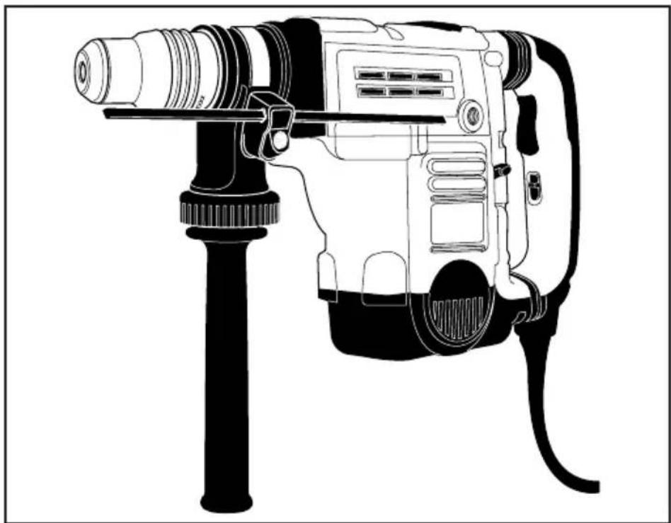
Description (fi g. 1, 2a-c)

WARNING: Never modify the power tool or any part of it. Damage or personal injury could result.
a. Trigger switch
b. Lock-on slider
c. Side handle
d. Main handle
e. Active vibration control
f. Mode selector switch
g. Electronic speed and impact control dial
h. Clamp wheel
i. Rear side handle position
j. Side handle clamp
k. Steel ring
I. Bush
m. Tool holder
n. Depth rod release button
o. Depth rod
p. Locking sleeve
q. Pin
x. Collar
y. Side handle knob
INTENDED USE
Your rotary hammer has been designed for professional rotary drilling and chipping applications.
DO NOT use under wet conditions or in presence of flammable liquids or gases.
These hammers are professional power tools.
DO NOT let children come into contact with the tool.
Supervision is required when inexperienced operators use this tool.
Soft Start Feature
The soft start feature allows the speed to build up speed slowly, thus preventing the drill bit from walking off the intended hole position when starting.
The soft start feature also reduces the immediate torque reaction transmitted to the gearing and the operator if the hammer is started with the drill bit in an existing hole.
Electronic Speed and Impact Control (fi g. 1, 3)
The electronic speed and impact control (g) offers the following advantages:
- use of smaller accessories without risk of breakage;
- minimised break-out when chiselling or drilling in soft or brittle materials;
- optimal tool control for precise chiselling.
Torque Limiting Clutch
The torque limiting clutch reduces the maximum torque reaction transmitted to the operator in case of jamming of a drill bit. This feature also prevents the gearing and electric motor from stalling. The torque limiting clutch has been factory-set and cannot be adjusted.
Complete Torque Control (fi g. 3)
NOTICE: Always turn the tool off before changing torque control settings or damage to tool may result.
The Complete Torque Control (CTC) feature of this tool is designed to provide additional control with a two-stage clutch mechanism. Refer to Setting the Torque Control Switch for more information.
Service Indicator LEDs (fi g. 3)
The yellow brushwear indicator LED (s) lights up when the carbon brushes are nearly worn out to indicate that the tool needs servicing within the next 8 hours of use.
The red service indicator LED (r) lights up if the lock-on button (b) is used in any mode except the chipping mode. The red indicator starts to flash if there is a fault with the tool or the brushes have completely worn out (refer to Brushes under Maintenance).
Fully Vibration-dampened Main Handle (fi g. 1)
The dampers in the side handle (c) absorb the vibrations transmitted to the user. This improves user comfort during the operation.
ENGLISH
Electrical Safety
The electric motor has been designed for one voltage only. Always check that the power supply corresponds to the voltage on the rating plate.

Your Berner tool is double insulated in accordance with EN 60745; therefore no earth wire is required.
If the supply cord is damaged, it must be replaced by a specially prepared cord available through the Berner service organisation.
Mains Plug Replacement (U.K. & Ireland only)
If a new mains plug needs to be fitted:
- Safely dispose of the old plug.
- Connect the brown lead to the live terminal in the plug.
- Connect the blue lead to the neutral terminal.

WARNING: No connection is to be made to the earth terminal.
Follow the fi tting instructions supplied with good quality plugs. Recommended fuse: 13 A.
Using an Extension Cable
An extension cord should not be used unless absolutely necessary. Use an approved extension cable suitable for the power input of this tool (see technical data).
The minimum conductor size is 1.5mm^2 ; the maximum length is 30m .
When using a cable reel, always unwind the cable completely.
ASSEMBLY AND ADJUSTMENTS

WARNING: To reduce the risk of injury, turn unit off and disconnect machine from power source before installing and removing accessories, before adjusting or changing setups or when making repairs.
Be sure the trigger switch is in the OFF position. An accidental start-up can cause injury.

WARNING: Tool bits may be hot and gloves should be worn when changing or removing them to avoid personal injury.
Assembling and Fitting the Side Handle (fi g. 2a, 2b)
The side handle (c) can be mounted in front or in rear position on either side of the machine to suit both RH- and LH-users.

WARNING: Always operate the tool with the side handle properly assembled.
MOUNTING IN FRONT POSITION (FIG. 2A)
- Snap the steel ring (k) over the collar (x) behind the tool holder (m). Squeeze both ends together, mount the bush (l) and insert the pin (q).
- Place the side handle clamp (j) and screw on the clamp wheel (h). Do not tighten.

WARNING: Once assembled, the side handle clamp should never be removed.
- Screw the side handle (c) into the bush (l). Tighten securely.
- Rotate the side handle mounting assembly to the desired position. For drilling horizontally with a heavy drill bit, we recommend to place the side handle at an angle of approx. 20^ for optimum control.
- Lock the side handle mounting assembly in place by tightening the clamp wheel (h).
MOUNTING IN REAR POSITION (FIG. 2B)
The rear position is particularly useful when drilling down into a floor.
- Unscrew the side handle (c) and remove it from the front position. Leave the side handle mounting assembly in front position.
- Screw the side handle directly into one of the rear side handle positions (i) on either side of the tool.
Inserting and Removing SDS Max™ Accessories (fi g. 1, 4a, 4b)
This tool uses SDS Max drills and chisels (refer to the inset in figure 4B for a cross-section of an SDS Max bit shank).
- Clean the bit shank.
- Pull back the locking sleeve (p) and insert the bit shank.
- Turn the bit slightly until the sleeve snaps into position.
- Pull on the bit to check if it is properly locked. The hammering function requires the bit to be able to move axially several centimetres when locked in the tool holder.
- To remove a bit pull back the tool holder locking sleeve/collar (p) and pull the bit out of the tool holder.
Selecting the operating Mode (fi g. 1)

Hammerdrilling:
for concrete, brick, stone and masonry drilling operations.

Hammering only: for chiselling and demolition applications. In this mode the tool can also be used as a lever to free a jammed drill bit.
- To select the operating mode, rotate the mode selector switch (f) until it points to the symbol of the required mode.
It may be necessary to twist the tool holder (m) slightly to allow the mode selector switch (f) to pass the O position.
- Check that the mode selector switch (f) is locked in place.
Indexing the Chisel Position (fi g. 5)
The chisel can be indexed and locked into 18 different positions.
- Rotate the mode selector switch (f) until it points towards the position.
- Rotate the chisel in the desired position.
- Set the mode selector switch (f) to the "hammering only" position.
- Twist the chisel until it locks in position.
Setting the Electronic Speed and Impact Control Dial (fi g. 1, 3)
Turn the dial (g) to the desired level. Turn the dial upwards for higher speed and downwards for lower speed. The required setting is a matter of experience. E.g.:
- when chiselling or drilling in soft, brittle materials or when minimum break-out is required, set the dial to a low setting;
- when breaking or drilling in harder materials, set the dial to a high setting.
Setting the Torque Control Switch (fi g. 3)
NOTICE: Always turn the tool off before changing torque control settings or damage to the tool may result.
Move the torque control lever (t) to setting 40Nm or 80Nm as needed for application.
Clutch Setting 40 Nm (u) is designed for most drilling applications and is designed to easily clutch out when the drill bit encounters re-bar or other foreign substances.
Clutch Setting 80Nm (v) is designed for higher torque applications such as corebits and deep hole drilling and is designed to clutch out at a higher torque threshold.
NOTE: Allow the motor housing to rotate a little while changing torque.
Each time the tool is plugged in, it will automatically default to clutch setting 1 into clutch setting 40Nm (u), the most sensitive setting.
Depth Rod (fi g. 1) (only BHD 5-1)
TO ADJUST THE DEPTH ROD
- Push in and hold the depth rod release button (n) on the side handle.
- Move the depth rod (o) so the distance between the end of the rod and the end of the bit equals the desired drilling depth.
- Release the button to lock rod into position. When drilling with the depth rod, stop when end of rod reaches surface of material.
OPERATION
Instructions for Use

WARNING: Always observe the safety instructions and applicable regulations.

WARNING: To reduce the risk of serious personal injury, turn tool off and disconnect tool from power source before making any adjustments or removing/ installing attachments or accessories.

WARNING: Tool bits may be hot and gloves should be worn when changing or removing them to avoid personal injury.

WARNING:
- Be aware of the location of pipework and wiring.
- Apply only a gentle pressure to the tool (approx. 20kg ). Excessive force does not speed up drilling but decreases tool performance and may shorten tool life.
Always hold the tool firmly with both hands and ensure a secure stance. Always operate the tool with the side handle properly assembled.
NOTE: Operating temperature is (-7 to +40^ C (19^ to 104^ F). Using the tool outside of this temperature range will decrease the life of the tool.
Proper Hand Position (fi g. 6)

WARNING: To reduce the risk of serious personal injury, ALWAYS use proper hand position as shown.

WARNING: To reduce the risk of serious personal injury, ALWAYS hold securely in anticipation of a sudden reaction.
ENGLISH
Proper hand position requires one hand on the side handle (c), with the other hand on the main handle (d).
Switching On and Off (fi g. 1)
To turn the tool on, depress the trigger switch (a).
To stop the tool, release the trigger switch.
The lock-on slider (b) allows the trigger switch (a) to be locked on in chiselling mode only. If the lock-on button is activated in drilling mode, as a feature the tool will switch off automatically.
To turn the tool on, press the trigger switch (a).
To stop the tool, release the switch.
For continuous operation, press and hold down the switch (a), slide the lock-on button (b) upwards and release the switch.
To stop the tool in continuous operation, press the switch briefly and release it. Always switch off the tool when work is finished and before unplugging.
Hammerdrilling
To turn the tool on, press the on/off switch (a).
To stop the tool, release the switch.
Drilling with a Solid bit (fi g. 1)
- Insert the appropriate drill bit.
- Set the mode selector switch (f) to the hammerdrilling position.
- Set the electronic speed and impact control dial (g).
- Fit and adjust the side handle (c).
- Mark the spot where the hole is to be drilled.
- Place the drill bit on the spot and switch on the tool.
- Always switch off the tool when work is finished and before unplugging.
Drilling with a Core Bit (fi g. 1)
- Insert the appropriate core bit.
- Assemble the centerdrill into the core bit.
- Set the mode selector switch (f) to the hammerdrilling position.
- Turn the electronic speed and impact control dial (g) to a medium or high speed setting.
- Fit and adjust the side handle (c).
- Place the centerdrill on the spot and switch on the tool. Drill until the core penetrates into the concrete approx. 1 cm.
- Stop the tool and remove the centerdrill. Place the core bit back into the hole and continue drilling.
- When drilling through a structure thicker than the depth of the core bit, break away the round
cylinder of concrete or core inside the bit at regular intervals.
To avoid unwanted breaking away of concrete around the hole, first drill a hole the diameter of the centerdrill completely through the structure. Then drill the cored hole halfway from each side.
- Always turn the tool off when work is finished and before unplugging.
Chipping and Chiselling (fi g. 1)
- Insert the appropriate chisel and rotate it by hand to lock it into one of 18 positions.
- Set the mode selector switch (f) to the hammering only position.
- Set the electronic speed and impact control dial (g).
- Fit and adjust the side handle (c).
- Turn the tool on and start working.
- Always turn the tool off when work is finished and before unplugging.
MAINTENANCE
Your Berner power tool has been designed to operate over a long period of time with a minimum of maintenance. Continuous satisfactory operation depends upon proper tool care and regular cleaning.

WARNING: To reduce the risk of injury, turn unit off and disconnect machine from power source before installing and removing accessories, before adjusting or changing setups or when making repairs. Be sure the trigger switch is in the OFF position. An accidental start-up can cause injury.
This machine is not user-serviceable. Take the tool to an authorised Berner repair agent after approximately 150 hours of use. If problems occur before this time contact an authorised Berner repair agent.
Brushes (fi g. 3)
The carbon brushes are not user-serviceable. Take the tool to an authorized Berner repair agent.
The yellow brushwear indicator LED (r) lights up when the carbon brushes are nearly worn out. After a further 8 hours of use or after the brushes have completely worn out the motor will automatically be shut off.
Tool maintenance needs to be carried out as soon as the service indicator (s) lights up.

Lubrication
Your power tool requires no additional lubrication.

Cleaning

WARNING: Blow dirt and dust out of the main housing with dry air as often as dirt is seen collecting in and around the air vents. Wear approved eye protection and approved dust mask when performing this procedure.

WARNING: Never use solvents or other harsh chemicals for cleaning the non-metallic parts of the tool. These chemicals may weaken the materials used in these parts. Use a cloth dampened only with water and mild soap. Never let any liquid get inside the tool; never immerse any part of the tool into a liquid.
Optional Accessories

WARNING: Since accessories, other than those offered by Berner, have not been tested with this product, use of such accessories with this tool could be hazardous. To reduce the risk of injury, only Berner, recommended accessories should be used with this product.
Various types of SDS Max drill bits and chisels are available as an option.
Consult your dealer for further information on the appropriate accessories.
Protecting the Environment
Separate collection. This product must not be disposed of with normal household waste.
Should you find one day that your Berner product needs replacement, or if it is of no further use to you, do not dispose of it with household waste. Make this product available for separate collection.

Separate collection of used products and packaging allows materials to be recycled and used again. Re-use of recycled materials helps prevent environmental pollution and reduces the demand for raw materials.
Local regulations may provide for separate collection of electrical products from the household, at municipal
waste sites or by the retailer when you purchase a new product.
Berner provides a facility for the collection and recycling of Berner products once they have reached the end of their working life. To take advantage of this service please return your product to any authorised repair agent who will collect them on our behalf.
You can check the location of your nearest authorised repair agent by contacting your local Berner offi ce at the address indicated in this manual.
GUARANTEE AND GUARANTEE SERVICE
Each tool, spare part or accessory is consistently checked before being dispatched from the manufacturing plant. If, despite this fact, there are any defects, please send the item directly to our Client Services Headquarters or to the nearest service repair shop of the firm Berner.
The guarantee period is 36 months and starts from the day of purchase, which must be proved by the original of the purchase document. During the guarantee period the producer guarantees:
- free removal of possible defects;
- free replacement of all damaged parts;
- free professional servicing.
The requirement is that these are material and/or manufacturing defects and that there has not been any inappropriate operation [of the machine]. Furthermore, only original accessory parts may be used, which Berner has expressly identified as suitable for the operation with Berner machines.
The addresses of repair workshops are given on the reverse side.
MARTEAUX COMBINÉS SDS MAX BHD 5-1, BHD 8-1
Felicitations!
Jorn Werner Ulrich Lindner
Chief Executive Chief Operations Officer (CEO) Officer Berner (COO)