VHHA075 - Receiver VIETA - Free user manual and instructions
Find the device manual for free VHHA075 VIETA in PDF.
Frequently Asked Questions - VHHA075 VIETA
User questions about VHHA075 VIETA
0 question about this device. Answer the ones you know or ask your own.
Ask a new question about this device
Download the instructions for your Receiver in PDF format for free! Find your manual VHHA075 - VIETA and take your electronic device back in hand. On this page are published all the documents necessary for the use of your device. VHHA075 by VIETA.
USER MANUAL VHHA075 VIETA
text_image
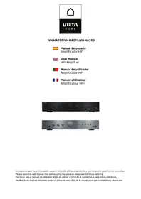
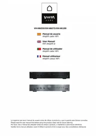
VIETA HOMEVH-HA050/VH-HA075/VH-HA100

Manual de usuario
Amplifi cador HIFI

User Manual
HIFI Amplifi er

natural_image
Front view of a black audio amplifier front panel with control knobs and buttons (no visible text or labels)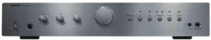
natural_image
Front panel of a silver audio amplifier with multiple knobs and buttons (no visible text or labels)VIETA
CONDICIONES DE GARANTÍA
text_image
Please decrease water!Conexión eléctrica
flowchart
graph LR
    A["220-240V AC~50Hz"] --> B["Switch"]
    B --> C["Device Module 1"]
    C --> D["Device Module 2"]
    D --> E["Device Module 3"]
    E --> F["Device Module 4"]
    F --> G["Device Module 5"]
    G --> H["Device Module 6"]
    H --> I["Device Module 7"]
    I --> J["Device Module 8"]
    J --> K["Device Module 9"]
    K --> L["Device Module 10"]
    L --> M["Device Module 11"]
    M --> N["Device Module 12"]
    N --> O["Device Module 13"]
    O --> P["Device Module 14"]
    P --> Q["Device Module 15"]
    Q --> R["Device Module 16"]
    R --> S["Device Module 17"]
    S --> T["Device Module 18"]
    T --> U["Device Module 19"]
    U --> V["Device Module 20"]
    V --> W["Device Module 21"]
    W --> X["Device Module 22"]
    X --> Y["Device Module 23"]
    Y --> Z["Device Module 24"]
    Z --> AA["Device Module 25"]

text_image
Maximum 6mMando a distancia de funcionamiento total para unidad Vieta
VH-CD030, VH-CD060, VH-HT010, VH-HR065, VH-HA050/075/100
VIETA AUDIO S.A. guarantees its products for a period of 24 months. The guarantee period starts on the date of purchase of brand new products that have never been used by the first end user.
This guarantee covers any possible manufacturing flaws for any Vieta products sold on Spanish territory by authorised distributors. Vieta products acquired in other countries will be covered by the guarantee supplied by the local distributor.
This guarantee will only be valid when accompanied by an invoice for the product that includes the client's name, the distributor and the date of purchase. VIETA AUDIO S.A. agrees to repair any product with a problem occurring during normal use as detailed in the user's manual and when being used for the purpose for which it was designed.
The guarantee will not be extended because a component is changed or the product is replaced.
INCIDENTS THAT ARE EXEMPT FROM GUARANTEE:
-
The guarantee period exceeds the stipulated time.
-
When the product has been handled by centres or personnel that are not authorised by VIETA AUDIO S.A.
-
When the product has been damaged by incorrect handling or use for purposes other than those it is intended for and that are not contemplated in the user's manual, or when it has broken pieces, scratches, cracks, wear and tear, damage produced by particles of paint, sand, water or food within the unit.
-
This guarantee does not cover expenses or damages caused by transport.
-
Loss, robbery or accidents produced by fire, liquid, chemical substances, excessive heat, inadequate ventilation, vandalism, electrical storms, incorrect or excessive power supply, lightening, impact, other external forces, radiation.
-
Any additional cost related to installing or uninstalling the product.
-
Products purchased outside Spanish territory or from distributors that are not authorised.
-
The data contained on our products (photo files, music, digital support, etc.) are not covered by the guarantee under any circumstance: it is the client's responsibility to make back up files before giving us the product. Likewise, any incorrect configuration or installation of software or incompatibility issues with hardware belonging to other equipment, including drivers and controllers.
-
Maintenance, repairs or parts replacement due to use and wear and tear.
-
Rechargeable and/or disposable batteries (life cycle depends on usage frequency).
-
Small faults or variations in the quality of the product that do not affect its value or the purpose for which it was created.
-
Negligence.
-
Accessories:
- Plugs and cases.
- Connector cables.
Headband
- Earlip and sleeve kits
• Decorative finishes.
- Any issue detected on receipt of the goods must be notified to customer care 902.367.607 or satogvietaees. In accordance with article 366 of trade law, VIETA AUDIO S.A. will not accept any claims regarding broken goods, impacts or missing packages 24 hours after the goods have been delivered.
CUSTOMER CARE / Tel. +34 902 367 607 / Fax. +34 93 574 26 83 / www.vieta.es
Contents
Safety Precautions....16
Important information....17
Connection to the mains 18
Remote Control Installation....19
Remote Control Operations 20 - 21
Front Panel Connections....22
Back Panel Introductions 23
Back Panel Connections 24
Troubleshooting....25
Technical data 26
Safety Precautions Important Information

A triangle with a lightning symbol draws the user's attention to "dangerous voltage" without insulation in the cabinet which may be high enough to entail a risk of electric shock.

A triangle with an exclamation mark draws the user's attention to important instructions for use and maintenance in the accompanying manual, which should be studied.

A symbol for CLASS II (double insulation)
WARNING: TO MINIMISE THE RISK OF FIRE OR ELECTRICAL SHOCK, DO NOT EXPOSE THE UNIT TO RAIN OR MOISTURE. DO NOT OPEN THE CABINET AS IT CONTAINS DANGEROUS VOLTAGE. ONLY QUALIFIED TECHNICIANS ARE ALLOWED TO CARRY OUT REPAIR AND SERVICE.
CAUTION: if the plug of the power cord needs to be replaced, it is important that the replacement is identical to the plug to be replaced, or that the new plug has been recommended by the manufacturer
TO AVOID ELECTRICAL SHOCK, IT IS IMPORTANT TO INSERT THE PLUG CORRECTLY INTO THE SOCKET.
Handling Instructions
- The top and back panel of the unit may become warm after prolonged use. This is not due to a defect.
- Turn off the power when the unit is not used.
Protect the power cord
- Follow the instructions below to prevent abnormal operation, electrical shock, fire or personal injury:
- Hold the plug firmly when inserting it into the socket.
- Avoid heat-producing devices.
- Do not place objects on the power cord.
- Do not carry out service work on or change the power cord.
Positioning
Do not place the unit in any of the fol. places: - In sunlight, close to heat-producing devices or in an enclosed rack.
- In places with high temperatures (40C or more) or high relative humidity (90% or more).
- In dirty places as some internal parts may be damaged.
Do not put your fingers or any other objects into the unit
- Touching the internal parts is dangerous and may cause injury or damage. Do not open the cabinet.
- Do not place any foreign matter in the unit.
Interference
Placing the unit near a television set, radio or video player may cause poor picture and sound quality. In that case, move the unit further away from the television set, radio or video player.
Condensation
Condensation may occur in the following cases:
- When the unit is moved directly from a cold to a warm place.
- When the unit is used in a room where the radiator has just been switched on or a place where the cold air from the air-conditioning system is directed at the unit.
- If the unit is used in the summer in a warm and humid room just after it has been moved from an air-conditioned room.
- If there is steam or a high level of humidity in the room.
In case of condensation, the unit will not work properly. Turn off the unit. Unplug the unit and leave it for 2-3 hours. The unit will then have adapted to the environment and any condensation will have disappeared.
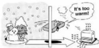
text_image
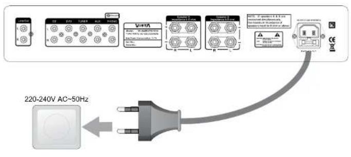
It's too warm!Connection to the Mains
text_image
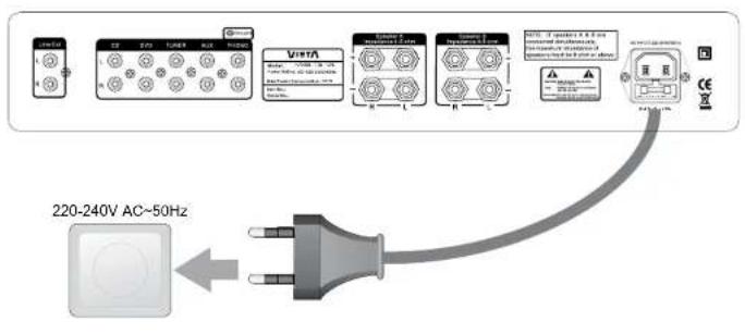
220-240V AC~50Hz
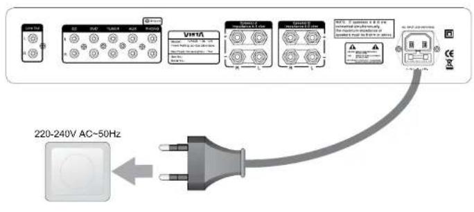
Do not turn on the power before all connections have been made correctly. Check that all connections have been made correctly before turning on the power. Check that the mains voltage is 220-240V AC50Hz before turning on the power.
Connection to the Mains
Check that all other connections have been made correctly before inserting the mains plug into the wall socket.
Then insert the plug into a suitable socket.
If the unit is to be used abroad, you may need an adapter.
Remote Control Installation
Installation of batteries
1 Remove the cover as illustrated.
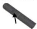
3 Replace the cover.
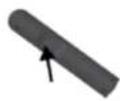
2 Position two batteries of the type AAA/R03/UM4 in the battery compartment. Make sure that the orientation of the batteries is correct (see drawing at bottom).
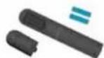
- Do not mix new and old batteries and do not use different types of batteries.
- If the remote control is not used for prolonged periods, remove the batteries from the remote control to avoid corrosion.
Using the remote control
Direct the remote control at the sensor on the front panel of the unit. When the remote control signal is received, the unit reacts accordingly. The remote control works within a range of 6 metres.
- Sometimes the remote control does not work well in strong light. You may have to move the unit if it is a problem.
- Malfunction may occur if other remote controls are used near the unit.
- Do not place any objects on the remote control, as the batteries may become flat if a key is depressed constantly.
- Make sure that there are no obstacles between remote control and unit.
- Do not position the unit behind tinted glass as it may reduce the maximum range of the remote control.
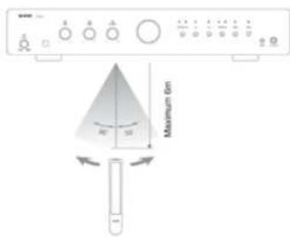
text_image
Maximum 6mFull function remote control for Vieta
VH-CD030, VH-CD060, VH-HT010, VH-HR065, VH-HA050/075/100
| 1-Power - Ect at the unit, into standby and ON. | √ | √ | √ | √ | √ | |||
| 2 Eject Open and close the disc tray. | √ | √ | × | × | ||||
| 3 Number (0,1-10, +10) | a. Number buttons (0,1~10, +10): selects b. Number buttons (0,1~10,-10): Note: +10 key could be pressed by 0 button; og 15, press +10 one time tumor preset 15, og. 25, by 2 times pressing | tracks on VH-CD030, VH-CD060, Save presets on VH-HT010 and VH-HR065. 10-eg.10, press +10, button and and then 5 to select CD track or +10 and then 5. | √ | √ | √ | √ | × | |
| 4 >> | Fast forwards in CD playback; Manual tuning | forward in tuner. | √ | √ | √ | √ | × | |
| 5 >I | PlayPause: Starts and pause playback. | √ | √ | × | √ | × | ||
| 6 >>I | Skip >>>/ Next: Selects the next track | in CD, and the next preset in tuner. | √ | √ | √ | √ | × | |
| 7 I<< | Skip >>>/ Previous: Selects the last track | In CD, and the last preset in tuner. | √ | √ | √ | √ | × | |
| 8 REPEAT | Repeat a single or all tracks in CD disc or | USB stick. | √ | √ | × | √ | × | |
| 9 PRO/ROM | PRO (Program) in CD060 only; ROM (Random) in CD030 only; | Programming tracks on a CD in a particular order. All tracks are played in random order. | √ | √ | × | × | × | |
| 10 << | Fast Rowinds in playback CD disc; Manual | tuning backward in Tunor. | √ | √ | √ | √ | × | |
Front Panel Connections
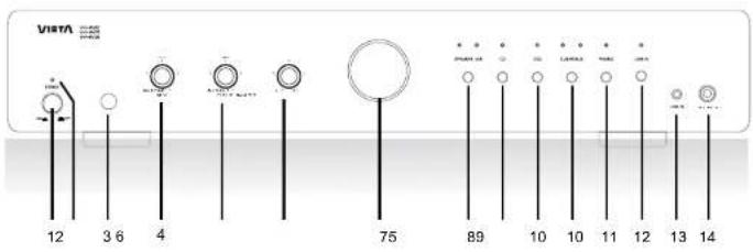
text_image
VISTA 12 3 6 4 75 89 10 10 11 12 13 14-
Mains switch: Used to turn ON/OFF the power.
-
LED: Lights off when VH-HA050/VH-HA075/VH-HA0100; turns on, lights blue when in standby mode.
-
Sensor: For getting the infrared ray signals of remote control operations.
-
Bases: Selects for adjusting the base (low frequency) up or down.
-
Treble: Selects for adjusting the treble (high frequency) up or down.
-
Balance: Selects for adjusting Right or Left channel of one pair of connected speakers.
Note: if turn the Right or Left to the end, the other channel will be no sound.
-
Volume knob: Tums up or down the volume.
-
Speaker A/B: Speaker selector, to choose pair-A or pair-B speakers to listen.
Note: there's 4 modes in the speaker selecting button (either in remote control);
Press 1st time (Default): Driver speaker A;
Press 2nd time: Driver speaker B;
Press 3rd time: Driver speaker A and B both on.
Press 4th time: Driver speaker A and B both off.
...again...
- CD: To activate CD source.
- DVD: To activate DVD source.
- TUNER/AUX: Press 1st time to activate TUNER source; press 2nd time to activate AUX source: ...again...
- PHONO: To activate PHONO source.
- LINE IN: To activate LINE IN source.
- Line in: 3.5mm mini jack source connector, like MP3 player, iPod, iPhone, etc.
- Headphone: 6mm headphone connector
Back Panel Introductions
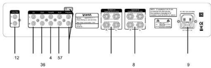
text_image
Line Set 12 36 4 57 ViMe VISA VISA 8 9- Line Out: For connection to an external amplifier
- Input CD: For connection of CD player or optional equipment.
- Input DVD; For connection of DVD player or optional equipment.
- Input Tuner: For connection of Tuner or optional equipment
b. Input AUX: For connection of someone optional equipment - Input PHONO: For connection of a turntable with an MM phono cartridge
Note: Ground Screw above inputs must be connected meanwhile.
- Speaker.A Left & Right: For connection to A pair of loudspeakers at 4-8 ohm.
- Speaker.B Left & Right: For connection to B pair of loudspeakers at 4-9 ohm.
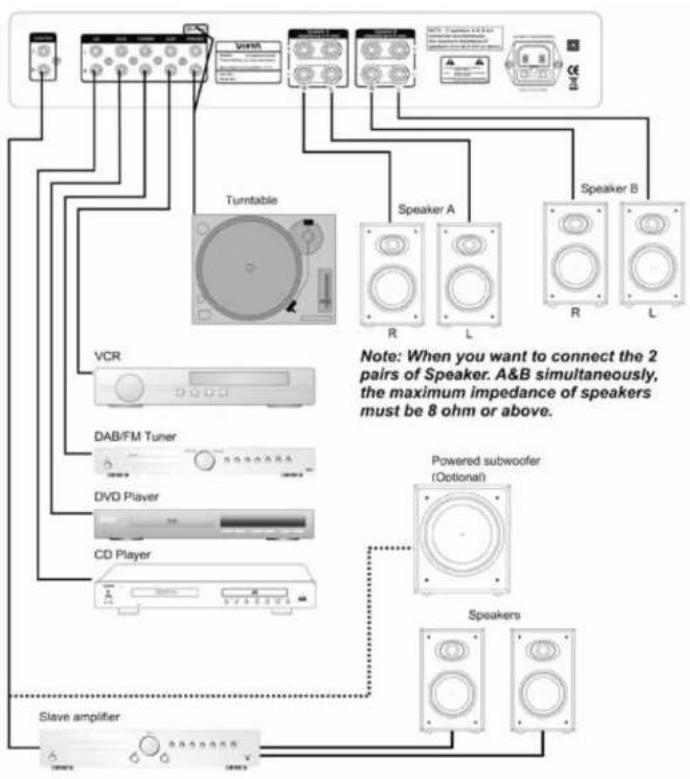
Note: When you want to connect the 2 pairs of Speaker, A&B simultaneously, the maximum impedance of speakers must be 8 ohm or above.
- AC Input: For connection of mains voltage.
Speaker Outputs Left and Right
To avoid damage to the amplifier, make sure it is NOT plugged into an AC outlet while connecting up or disconnecting speaker wire to the speaker outputs. The amplifier has two pair of speaker outputs on the back labeled Speaker Left and Speaker Right. Using a suitable speaker wire, connect the right speaker (of Speaker A or B) to the Speaker Right connectors and the left speaker to them Speaker Left (of Speaker A or B). Pay careful attention to match the positive (red) and negative (black) terminals on your speakers to the positive (red) and negative (black) terminals on back of the amplifier.
Connection with Amplifier
Check that the Power Switch on front of the amplifier is in the off position. Push the plug (LC line socket) of the power cable supplied with the amplifier into the socket (AC INPUT) on back of the unit. Make sure it is pressed in firmly. Plug the other end of the power cable into an AC wall outlet.
flowchart
graph TD
    A["Speaker A"] -->|R| B["Turntable"]
    C["Speaker B"] -->|L| B
    D["VCR"] --> E["DAB/FM Tuner"]
    F["CD Player"] --> G["CD Player"]
    H["Slave amplifier"] --> I["Switch"]
    J["Powered subwoofer (Optional)"] --> K["Speakers"]
    style A fill:#f9f,stroke:#333
    style C fill:#f9f,stroke:#333
    style D fill:#ccf,stroke:#333
    style F fill:#ccf,stroke:#333
    style H fill:#ccf,stroke:#333
    style J fill:#ccf,stroke:#333
    note right of A: Note: When you want to connect the 2 pairs of Speaker. A&B simultaneously, the maximum impedance of speakers must be 8 ohm or above.
    note right of J: Powered subwoofer (Optional)
Troubleshooting
| PROBLEM | CAUSE/REMEDY | |||
| No power when the amplifier is -Switch on the electric current at the socket. turned on.-Check that the plug has been correctly insertedintothesocket.-The internal fuse has blown and must be replaced by a qualified service technician. | ||||
| No sound.-The power cord has been damaged and must bereplaced.-The amplifier has not been turned on.-The volume control is set at a minimum.-The speaker cables have not been correctlyconnected.-A wrong input source has been selected.-No input source has been connected. | ||||
| There is sound in one channel-The audio input cables or speaker cables only.have been incorrectly connected or damaged.-Theinputsourceis- Thespeakersaredef | ||||
| High buzzing.-The audio input cables have been incorrectlyconnectedordamaged.-The ground cable for the record player has notbeenconnected.-The record player pick-up is defective. | ||||
| Weak bass and poor stereo perspective.-The speaker connection is out of phase. Check that the positive and negative poles have been correctly connected, both at the back of the amplifier and atthebackofthe | ||||
| Distortion of sound.-Some of the conductor wires of the speaker cable are in contact with each other which causesdistortion.-The volume is set too high. | ||||
| The unit does not switch between input-The amplifier is defective and should be serviced modes,by a qualified technician. | ||||
Technical data
TECHNICAL DATA
Phone input
Input impedance 47K Ohm
Input sensitivity 10.0 mV
Line level inputs
Input impedance 47K Ohm
Input sensitivity 400 mV
Line level outputs
Output impedance Line out 10K Ohm
Headphones 32 Ohm
Maximum output level Line out 250 mV
Headphones 2.0 V
Tone control
Treble +/- 14 dB
Bass +/- 14 dB
Output power
VH-HA050 = 2 x 30 Watt at 4 Ohm
VH-HA075 = 2 x 50 Watt at 4 Ohm
VH-HA100 = 2 x 75 Watt at 4 Ohm
Frequency response: 10Hz to 80KHz (-3 dB)
Distortion: <0.2%
Signal/noise ratio: >80 dB
Dimensions (H x W x D): 70 x 430 x 285 mm
Net Weight:
VH-HA050 =4.55 kg
VH-HA075 =4.80 kg
VH-HA100 =4.80 kg
Supplied Accessories:
- User manual
- Mains Lead
- Remote Control
We reserve the right to change the technical data and the design of the product without notice as a result of further development.
VIETA
CONDIÇÕES DE GARANTIA
Conexões Painel Frontal 36
text_image
Have decreased cost!CONEXÃO À CORRENTE PRINCIPAL
flowchart
graph LR
    A["220-240V AC~50Hz"] --> B["Power Supply"]
    B --> C["Device Module 1"]
    B --> D["Device Module 2"]
    B --> E["Device Module 3"]
    B --> F["Device Module 4"]
    B --> G["Device Module 5"]
    B --> H["Device Module 6"]
    B --> I["Device Module 7"]
    B --> J["Device Module 8"]
    B --> K["Device Module 9"]
    B --> L["Device Module 10"]
    style A fill:#f9f,stroke:#333
    style B fill:#ccf,stroke:#333
    style C fill:#cfc,stroke:#333
    style D fill:#cfc,stroke:#333
    style E fill:#cfc,stroke:#333
    style F fill:#cfc,stroke:#333
    style G fill:#cfc,stroke:#333
    style H fill:#cfc,stroke:#333
    style I fill:#cfc,stroke:#333
    style J fill:#cfc,stroke:#333
    style K fill:#cfc,stroke:#333
text_image
Maximum GainFUNCIONAMENTO COMPLETO DO CONTROLO REMOTO PARA UNIDADE VIETA
VH-CD030, VH-CD060, VH-HT010, VH-HR065, VH-HA050/075/100