CCD 60 GL - Basket CORBERO - Free user manual and instructions
Find the device manual for free CCD 60 GL CORBERO in PDF.
| Product Type | Kitchen Hood |
| Brand | Corbero |
| Model | CCD 60 GL |
| Intended Use | Domestic, extraction of cooking fumes and vapors |
| Operating Modes | External evacuation or internal recirculation (with charcoal filter) |
| Dimensions (W x D x H) | 60 cm width (model 60 GL) |
| Minimum distance from cooking surface | 50 cm for electric cooktops, 65 cm for gas or mixed cooktops |
| Electrical Supply | Voltage according to rating plate (usually 220-240 V) |
| Lighting Power | Halogen lamp 12 V - 20 W max, type G4 |
| Controls | Control panel with buttons for light and 3 suction speeds |
| Grease Filter | Removable, regular cleaning (at least once a month) |
| Active Carbon Filter (recirculation) | Cleanable every 2 months, replace pad every 3 years |
| Chimney Material | Telescopic chimney (metal) |
| Installation | Wall-mounted with drilling template included |
| Air Outlet Diameter | Equivalent to air outlet (pipe not supplied) |
| Safety | Disconnect before maintenance; do not use without filter; respect minimum distance |
| Maintenance | External cleaning with damp cloth and mild detergent, no alcohol or abrasives |
| Weight | Approximately 12 kg (estimated) |
| Included Accessories | Drilling template, plugs, screws, user manual |
| Optional Accessories | Active carbon filter, exhaust pipe |
Frequently Asked Questions - CCD 60 GL CORBERO
User questions about CCD 60 GL CORBERO
0 question about this device. Answer the ones you know or ask your own.
Ask a new question about this device
Download the instructions for your Basket in PDF format for free! Find your manual CCD 60 GL - CORBERO and take your electronic device back in hand. On this page are published all the documents necessary for the use of your device. CCD 60 GL by CORBERO.
USER MANUAL CCD 60 GL CORBERO
EN - Instruction on mounting and use
Closely follow the instructions set out in this manual. All responsibility, for any eventual inconveniences, damages or fires caused by not complying with the instructions in this manual, is declined. The hood is conceived for the suction of cooking fumes and steam and is destined only for domestic use.
The hood can look different to that illustrated in the drawings in this booklet. The instructions for use, maintenance and installation, however, remain the same.
! It is important to conserve this booklet for consultation at any moment. In the case of sale, cession or move, make sure it is together with the product.
! Read the instructions carefully: there is important information about installation, use and safety.
! Do not carry out electrical or mechanical variations on the product or on the discharge conduits.
! Before proceeding with the installation of the appliance verify that there are no damaged all components. Otherwise contact your dealer and do not proceed with the installation.
Note: the elements marked with the symbol () are optional accessories supplied only with some models or elements to purchase, not supplied.

Caution
WARNING! Do not connect the appliance to the mains until the installation is fully complete.
Before any cleaning or maintenance operation, disconnect hood from the mains by removing the plug or disconnecting the mains electrical supply.
Always wear work gloves for all installation and maintenance operations.
The appliance is not intended for use by children or persons with impaired physical, sensorial or mental faculties, or if lacking in experience or knowledge, unless they are under supervision or have been trained in the use of the appliance by a person responsible for their safety.
This appliance is designed to be operated by adults, children should be monitored to ensure that they do not play with the appliance.
This appliance is designed to be operated by adults. Children should not be allowed to tamper with the controls or play with the appliance.
Never use the hood without effectively mounted grating!
The hood must NEVER be used as a support surface unless specifically indicated.
The premises where the appliance is installed must be sufficiently ventilated, when the kitchen hood is used together with other gas combustion devices or other fuels.
The ducting system for this appliance must not be connected to any existing ventilation system which is being used for any other purpose such as discharging exhaust fumes from appliances burning gas or other fuels.
The flaming of foods beneath the hood itself is severely prohibited.
The use of exposed flames is detrimental to the filters and may cause a fire risk, and must therefore be avoided in all circumstances.
Any frying must be done with care in order to make sure that the oil does not overheat and ignite.
Accessible parts of the hood may became hot when used with cooking appliance.
With regards to the technical and safety measures to be adopted for fume discharging it is important to closely follow the regulations provided by the local authorities.
The hood must be regularly cleaned on both the inside and outside (AT LEAST ONCE A MONTH).
This must be completed in accordance with the maintenance instructions provided in this manual). Failure to follow the instructions provided in this user guide regarding the cleaning of the hood and filters will lead to the risk of fires.
Do not use or leave the hood without the lamp correctly mounted due to the possible risk of electric shocks.
We will not accept any responsibility for any faults, damage or fires caused to the appliance as a result of the non-observation of the instructions included in this manual.
This appliance is marked according to the European directive 2002/96/EC on Waste Electrical and Electronic Equipment (WEEE). By ensuring this product is disposed of correctly, you will help prevent potential negative consequences for the environment and human health, which could otherwise be caused by inappropriate waste handling of this product.
The symbol on the product, or on the documents accompanying the product, indicates that this appliance may not be treated as household waste. Instead it should be taken to the appropriate collection point for the recycling of electrical and electronic equipment. Disposal must be carried out in accordance with local environmental regulations for waste disposal.
For further detailed information regarding the process, collection and recycling of this product, please contact the appropriate department of your local authorities or the local department for household waste or the shop where you purchased this product.
Use
The hood is designed to be used either for exhausting or filter version.
Ducting version
The hood is equipped with a top air outlet B for discharge of fumes to the outside (exhaust pipe and pipe fixing clamps not provided). Connect the hood and discharge holes on the walls with a diameter equivalent to the air outlet (connection flange).
Using the tubes and discharge holes on walls with smaller dimensions will cause a diminution of the suction performance and a drastic increase in noise.
Any responsibility in the matter is therefore declined.
Attention! If the hood is supplied with carbon filter, then it must be removed.
Filter version
Should it not be possible to discharge cooking fumes and vapour to the outside, the hood can be used in the filter version, fitting an activated carbon filter and the deflector F on the support (bracket) G, fumes and vapours are recycled through the top grille H by means of an exhaust pipe connected to the top air outlet B and the connection ring mounted on the deflector F (exhaust pipe and pipe fixing clamps not provided).
Attention! If the hood is not supplied with carbon filter, then it must be ordered and mounted.
The models with no suction motor only operate in ducting mode, and must be connected to an external suction device (not supplied).
The connecting instructions are supplied with the peripheral suction unit.
Installation
The minimum distance between the supporting surface for the cooking equipment on the hob and the lowest part of the range hood must be not less than 50cm from electric cookers and 65cm from gas or mixed cookers.
If the instructions for installation for the gas hob specify a greater distance, this must be adhered to.

Electrical connection
The mains power supply must correspond to the rating indicated on the plate situated inside the hood. If provided with a plug connect the hood to a socket in compliance with current regulations and positioned in an accessible area, after installation. If it not fitted with a plug (direct mains connection) or if the plug is not located in an accessible area, after installation, apply a double pole switch in accordance with standards which assures the complete disconnection of the mains under conditions relating to over-current category III, in accordance with installation instructions.
Warning! Before re-connecting the hood circuit to the mains supply and checking the efficient function, always check that the mains cable is correctly assembled.
Mounting
Before beginning installation:
- Check that the product purchased is of a suitable size for the chosen installation area.
- Remove the charcoal (*) filter/s if supplied (see also relative paragraph). This/these is/are to be mounted only if you want to use the hood in the filtering version.
- Check (for transport reasons) that there is no other supplied material inside the hood (e.g. packets with screws () , guarantees () , etc.), eventually removing them and keeping them.
- If possible, disconnect and move freestanding or slide-in range from cabinet opening to provide easier access to rear wall/ceiling. Otherwise put a thick, protective covering over countertop, cooktop or range to protect from damage and debris. Select a flat surface for assembling the unit. Cover that surface with a protective covering and place all canopy hood parts and hardware in it.
- In addition check whether near the installation area of the hood (in the area accessible also with the hood mounted) an electric socket is available and it is possible to connect a fumes discharge device to the outside (only suction version).
- Carry out all the masonry work necessary (e.g. installation of an electric socket and/or a hole for the passage of the discharge tube).
Expansion wall plugs are provided to secure the hood to most types of walls/ceilings. However, a qualified technician must verify suitability of the materials in accordance with the type of wall/ceiling. The wall/ceiling must be strong enough to take the weight of the hood. Do not tile, grout or silicone this appliance to the wall. Surface mounting only.
Installation wall model
When the vapour catcher is disassembled, it must be fixed as shown in Fig. a,b.
The electric connection box must be assembled as shown in
Fig. c,d,e.
Fig. 5
- Drawing a line on the wall with a pencil up to the ceiling, corresponding to the centre line, will make the installation operations easier.
- Apply the perforation diagram to the wall: the vertical centre line printed on the perforation diagram should correspond to the centre line drawn on the wall. In addition, the lower edge of the perforation diagram corresponds to the lower edge of the hood.
- Make holes as indicated on the template, insert the wall dowels and screw 2 screws into the upper holes, leaving a space of about 1cm between the head of the screw and the wall.
Note: Always make the holes indicated on the template. The upper 2 are for hooking the hood up while the lower holes (generally 1 central or more lateral) are for the definitive and safety fixing.
- Apply flues support bracket G^ to the wall touching the ceiling. Use the flues support bracket as a perforation diagram (the small slot in the support must coincide with the line previously drawn on the wall, if present), and mark two holes with a pencil. Make the holes and insert 2 dowels.
- Fix the flues support bracket to the wall with 2 screws.
- Hang the hood to the two upper screws (see installation phase 3).
- Introduce and screw the screws (and washer(s)) up into the hole(s) for the definitive fixing (COMPULSORY!!). Then, having checked the setting of the hood, TIGHTEN ALL THE upper and lower SCREWS.
Note: the lower fixing points are visible removing the fats filters and they are at the sides and/or at the centre of the hood (after having removed the frame of the carbon filter, if present, in the latter case).
In any case, we recommend using the lateral holes, when available, to increase the stability of the hood.
- Connect a tube (tube and bands for fixing not supplied, to be purchased) for discharging the fumes to the connection ring placed over the aspiration motor unit.
The other end of the tube should be connected to a device for expelling fumes on the outside of the hood in the aspiration version. If you want to use the filtering version, fix deflector F to flues support bracket G and connect the other end of the tube to the connection ring placed on deflector F.
- Connect the electricity.
- Apply the flues and fix them above with 2 screws (10a) to flues support bracket „G“ (10b).
- Slide the lower section of the flue down to cover the aspiration set until inserting it completely into the opposite housing over the hood. Remount the carbon filter frame and the fat/s filter/s and check the perfect functioning of the hood.
Description of the hood
Fig. 1
- Control panel
- Grease filter
- Grease filter release handle
- Halogen lamp
- Vapour catcher
- Telescopic chimney
- Air outlet (used for filter version only)
Operation
The hood is fitted with a control panel with aspiration speed selection control and a light switch to control cooking area lights.
Model with 4 push Buttons control panel
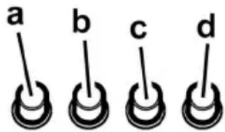
a. ON/OFF light switch
b. Speed 1/OFF switch
c. 2-speed selection
d. 3-speed selection
Model with 5-key keyboard
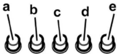
a. on/off light switch
b. off aspiration switch
c. minimum power selection aspiration switch
d. medium power selection aspiration switch
e. maximum power selection aspiration switch
Maintenance
ATTENTION! Before performing any maintenance operation, isolate the hood from the electrical supply by switching off at the connector and removing the connector fuse.
Or if the appliance has been connected through a plug and socket, then the plug must be removed from the socket.
Cleaning
The cooker hood should be cleaned regularly (at least with the same frequency with which you carry out maintenance of the fat filters) internally and externally. Clean using the cloth dampened with neutral liquid detergent. Do not use abrasive products. DO NOT USE ALCOHOL!
WARNING: Failure to carry out the basic cleaning recommendations of the cooker hood and replacement of the filters may cause fire risks.
Therefore, we recommend observing these instructions.
The manufacturer declines all responsibility for any damage to the motor or any fire damage linked to inappropriate maintenance or failure to observe the above safety recommendations.
Grease filter
Traps cooking grease particles.
To remove the grease filter, pull the spring release handle.
Fig. 2
Charcoal filter (filter version only)
Fig. 3
It absorbs unpleasant odours caused by cooking.
The charcoal filter can be washed once every two months using hot water and a suitable detergent, or in a dishwasher at 65^ (if the dishwasher is used, select the full cycle function and leave dishes out).
Eliminate excess water without damaging the filter, then remove the mattress located inside the plastic frame and put it in the oven for 10 minutes at 100^ C to dry completely. Replace the mattress every 3 years and when the cloth is damaged.
Remove the filter holder frame by turning the knobs (g) 90^ that affix the chimney to the cooker hood.
Insert the pad (i) of activated carbon into the frame (h) and fit the whole back into its housing (j).
It is possible to use a traditional carbon filter, neither washable nor regenerable, to be replaced every 3 - 4 months. The filter holder frame of the carbon filter is welded together; the eventual frame supplied with the hood is not, therefore, to be used.
Insert it into its housing and fix it turning the 2 plastic knobs.
Replacing lamps
Disconnect the appliance from the electricity.
Warning! Prior to touching the light bulbs ensure they are cooled down.
Replace the old light bulb with the one of the same type as specified in the feature label or near the light lamp on the hood.
Fig. 4
- Using a flat head screwdriver or equivalent tool, carefully pry loose the light cover.
- Remove the damaged light and replace with a new 12 Volt, 20 Watt (Maximum) halogen light made for a G-4 base SUITABLE FOR USE IN OPEN LUMINAIREs. Follow package directions and do not touch new light with bare hands.
- Reinstall the light cover. (it will snap shut).
If the lights do not work, make sure that the lamps are fitted properly into their housings before you call for technical assistance.
He octabnayTe DeTei 6e3 npncmOTpa, YTo6bl OHN He nIgpanC npnbopom.
He nCnoJb3yIe BblTgKky, ecn peWetka HnpaBnBHO yctaHObnHeHa!
Kateropnueeckn 3anpeaetcN cnoNb3OBaTb BbITkky BaqueCTBe ONOPHO nnockoctn, eCNI 3TO CneuNaBHo He orObopeHo.
ObecneBte Hndnexkaun Bo3dyxoo6meh nomeeHna, KOrda BbncnIb3yeTe BbITKky B kyxHe OndHOpeMeHHo C npyHMnpnbopam Ha ra3y nnHa dpYrom rOpouem.
BbITraBaEmbI BO3dyX He DoJIXe Hb6paCbIBaTcHapxUy
Yepe3 BO3dyXoBOd, NcIONb3yeMbI dN Bb6pOcA dbIMOB OT
Pn6OpOB C r3OBbIM CxNirAHem IN C nNTaHEm DpymMn
rOpUHM.
Kateropueckn 3anpeuaeTcra roTOBntb 6nOda HaI pIaMeHem, nCKoJIbky CBO6oDHOe PIIaMMy MOXe TNOBpeDHTb fNtbpI n CTaTb npuHHoN IOxapa; N03ToMy, BO3depKINBAInTeCB O TTO R B IIO6OM Cnyae.
KapeHbe B 60JIbIOM KOJINUcEeTBe Macna DOJXHO npOn3BOIDITbcr NOI NOCTOARHHbIM KOHTpONeM, IMeR B BVHy, YTO NepepeToe MACIO MOKeT BOCIIaMeHrTbcr.
Pn nCnoB3OBaHm BMeCTe C npOuHM annapaTaMn DnBapKn,OTKpbTbIe Yactn np6oopa MoTy CnBHo HArpeBaTbcra.
YTO KacaetcayexHuecknx Mepn yCNOBn no TexHnke 6e3oNaChOCTn npn OTBODe NbIMOB, TO npnpeKnBaTecb CTPOrnpaBn, npedyCMOTpeHHbIX perIameHTOM MeCThIx KOMNTeHTbIX BlaCTeN.
Ipon3BOJNTe nepnoDnueckyUO OuNCTky BbITJxKn KaK BHyTpN, TaK n chapyKn (IO KPAHHeM MEPE, PA3 B MECaLc c co6JIIODeHnEM ycNoBn, KOtOpbIe CneuaNbHO npedycMOteHb I HnCtpyKunX NO ObcnyKuBaHIO DaHHoro np6opa).
HecobIIOHe HnCTpyKmNo YnCTKe BbITaKKn N NO 3ame He n YnCTKe pNtpoB MoKet CtaTb npuHHoN noXapa.
He nCnoJb3yIte Hn He ocTabJIaIe BbITJkKy 6e3 npabNlboHo yCTaHOBJIeHHbIX JAMIOueK B CB3N C BO3MOXHbIM PNCKOM yDapa 3JIeKTPuYeCKM TOKOM.
Mbl CHMaem C ce6yIO OTBeTCTBHeHOctb 3a HEnoJaKn, yuep6 nnn cropanhe npnbopa BCJeDCTBne HecobJIOeHn HNCTpyKuIN, npNBedeHHbIX B daHHOM pyKOBOdCTBE.
JaHHoe n3dJIne npomapKnpoBaHO B COOTBETCTBnC Ebponecko DnpeKtNBo0 2002/96/EC no ytnJIn3aunn 3JNEKtpueckoro n3JKeKtpoHnro obOpyDobAHn (WEEE).
ObecneuB npabnIbHyU ytnnn3aunD aHHoro n3deNna, Bbl NOMOKeTe npedOTBpaTntb NOTeHuaNbHbIe HcraTNBbIe NocJeDCTBnI dno OkpykaIoSeI cpebl 3doOpBBy eNoBeka.

CnMBOI Ha cAMOM n3deJIN mJIn COpOBoIteJIbHO JOKymeHTaQnn Yka3bIbaeT, yTO npYtUN3aun DaHORo N3deJIN C Hm HEnb3r O6paataBcK KAC C ObHybIMN 6bITOBbIMN OTXoamn. BMeCTO 3TORO, eRO CNeDyET CdaBaT B COOTBeTCTByIOuN NyHKT npneMKn 3JeKTPueckoro IN 3JeKtpoHHORO obopydOBAHn DnR nocJeDyUoien yTNI3aun.
CdaHa HcnoMdoJxHa npOn3BODnTbC B COOTBeCTBn C MeCTHbIMN npabUNAMN NO yTNIN3aun OTXoOB.
3a 60nee noDpo6HOn nHΦopMauné O npabnax o6paueHHc TaKMMn N3dEeNMAH, IN x yTnIIN3aUNn IN nepepa6OTKn O6paauTeCb B MeCTbIE OpraHbI Bnactn, B Cnyk6y NO yTnIIN3aUNn OTXoDOB INB Mara3HN, B KOtOpom Bbl npno6peJI DaHHoe N3dEIne.
Повьзованe
BbITaKa cKoHcTpynOpBaHa IJI pa6OtI BpeXmme OTB0da BO3dyxa HApKy IIN peUpkyIaNn BO3dyxa.
IcnoJIHeHne cOTbOdom Bo3dyxa
BbIgKc Ch6xHea BepxHm BbIOHbIM OTBepCTnem B IINBbIpc0a DbIMOB HApKy (NcNOJIHeHne C OTBOOM BO3yHaHapKy-BbIOHnA Tpy6a N XOMyTbI KpeJIeHnE He BXoJrB KOMNKeT). POnCOeHNHTb BbITAKy K BbIOHOI Tpy6e cDnAmETpOM COOTBeTCTByOuHM OTBepCTnO BbIXOa BO3yXa (coeHNHTeNbHbI φJaHeU).
YctaHOBka Tpy6 C MeHbUIM DnAmETpOM DaCT yMeHbUeHne MOUHOCTN BCacbIBAHN B03dYxa N pe3Koe yBeJIuYeHne yPOBHa UyMa.
PpOIN3BOIDNTeIb CHIMaET C Ce6B BCaKyIO OTBeTCTBeHHOCtB IO OTHOWEHNI BbIe CKa3aHHOrO.
BHHMaHHe! Ecnn BbITaXka Cha6KeHa yroIbHbIM cnIbTpom, to y6epnte ero.
IcnoJIHeHne COTBODOM BO3aYxa
EcnIO TBOD bIMOB n napOB HApxky HeBO3MOxH Bbl MoXeTe NOIb3OBA TcB bITKoB B pexime CpeuPKyIauei npn NOMOu yroIbHbIX QINbTPOB uYCTAHOBKn DePJIeKTopa F Ha KPOHHTeIH G. TaKIM O6pa3OM OUYUeHHbI ON DbIMOBbIX napOB BO3dyx BO3BpaauetcB NOMEueHne uepe3 BepxHIOpeWETKY H N BbIBODHyTO Tpy6y, NOCDoeHNReMyK BepxHemy BBIOHDomy OTBepCTNIO B, npn NOMOu COeHNHTeJbHOrOKoJIbca, CMOTnpOBaHHORO Ha DePJIeKTope F (BBIOHDa Tpy6a N XOMyTb KpeJIeHNA HE BXOJAT B KOMJIeKT NoCTABKN).
BHHMaHHe! EcIn BbITaXka He Cha6KeHa yroIbHbIM ΦnIbTpOM, To 3aKaXnTe n YcTaHOBnTe erO nepei NCNoJIb3OBaHMe.
MoJIeN BbITJKeK 6e3 MOTOPHOrO 6Ioka MoryT pa6oTaTB OdHOM pexIMe OTBODa BO3DyXa HApxKy, IO3TOMy OH NIOJHXbl 6bITb NOCDoeINHeHbIK BHeUHeN BbITJXHOY yCTaHOBKe (HE BXOINT B NOCTaBky).
HCTpyKmno COeINHEHnM NOCTABJYOTc C nepuepnHbIM BbITXHbIM y3IOM.
YctaHOBka
PacctoHHe HxHHe IpaHbBbTJkN HAD onOpHOIIOCKOCTbIO NOcCocyDbI Ha KxyOHHOIINTe DOJXHO 6bITb He Mehee 50cm -nra 3JIeKTPnuecknx PnIT, n He Mehee 65cm dIra3OBbIX INIKOM6HHPOBaHHbIX PnNT.
EcINB INHCTpykunxno yctahOBKe ra3OBoI pNTbI orObopeHO 6oJIbwee pacCToRnHe,To yUTnte 3TO.

3NeKtpnueckoe coeHHeHne
HapjEHe Cetn DoJHKHO COOTBETCTBOBAtb HapjEHHIO, yka3aHHOMy Ha Ta6nUcKe Texnuecknx DaHHbIX, KOtopa pa3MeIeHa BHTpN np6opA. Ecn BBtJkKa Ch6KeHa BNKo, NOKIOuHTe BbITKky K wTeNCbHOMy pa3bemy. OH DOJKeH OTBeYATb DeICTByOuIM mPabINam N 6bITb pacNOJoxEh B JERKOIOCTynHom MeCTe. BKIOUHTb B po3ETky MOXHO NocJe YCTAHOBKn. Ecn Je BbITJkKa He Ch6KeHa BNKo (npAmoe NOKIOUChEna K cTeN), INN WTENCbHbI pa3bEm He paCNOJIOxEh B IOCTynHom MecTe, TAOKe I NOcNe YCTAHOBKn, TO NCNOB3yIne HAJIEXaUIN DByXNOIOCHbI BbIKIOUaTeNb, ObecneuBAIoU nnONHe pa3MbkaHne CETn Pn BO3NHKOHEHm YcNoBn nepeHApJxKeHn 3-e KaterOpMn, B COOTBETCTBN C INHCTpyKUmaM n O yCTAHOBKe.
BhimaHne! npexJe Yem NOKIOUHTb K CeTn nHTaHna 3JIeKtpuYeCKyO CnCTEmy BbITJxKn I pOBepNTb NcnpaBHOe fHyHKUHOHPOBaHne ee y6eIHTecb B TOM, YTO Ka6eNb nHTaHna PpaBUNbHO CMOHTpOBAH.
YctaHOBka
Ipeed HaayaJOM MOnTaJa:
IpoBepbTe, TTo6bI pa3Mepbl npNo6peTeHHoro Bamn H3dEINr NIOxOINK Bbl6paHHOMy MecTy erO MoHTaxa.
CHIMITE yroBbHbI ΦnbTp/bI, ecn OH N IMeIOTCr (CMOTPe TaKke cooTBeTcTByIOuI pa3deJ).ΦNbp/bI yctahabINBaIOTCra 6paTHO, TOnbKO ecn Bbl XOTTe NCNoB3OBaTb BbITkKBypeXmpeUpkyIaI.
IpoBepbTe, TTo6bl BHyTpN BbITaXKn He octBaJIoCb npEdMeTOB, NOMEeHHbIX Tyda Ha Bpemr ee TpaHCnOpTnpOBk) (HaNPmEp, NaKeTnKOB C wypynAm, INCTKOB rapaHTnn n T.D.), eCIN OHN IMeOTcR, BblbTe INx IN coxpaHNTe.
IIO BO3MOXHOCTN OTCOEHNHTE N OTOBUNHBTE KXYOHHBIE 3JIeMeHTbI, paCNOLOXeHHbIE NOB BbITJxKoN I PdOM C 30HO ee MOHTaKa, dIy oEbcneueHn6 BoJeE cBO6OHorO DoCTyna K NotOLKy/CTeHaM, K KOtOpbIM 6yDet KpeNTbcra BbITJxKa. EcIN 3TO HeBO3MOxHO, KaK MoXHO TuaTeNbHee npedoxpaHnTe MeBeN b IpOuHne npEdMetbHa Bpem MaHTaxa. BbIbepnte pOBHyO IOBepxHOCTb, NOKpoTte ee 3aunTHbIM NOKpbITnEM n pa3IOXHTe Ha He BbITJxKy N KpeNXbIe DeTaII.
- Поберп te takke, чобbl радom c 30но мотра Кьыгки (В 30е, ДОТуннoi takke посne мотра Кьыгки) Имелась сетвая розетка и OTBERPCTne ДлядьIMoxOda, OTBOДЯшee Дыm Ha улИцу (ТольКО B pexиme OTbOda).
BbINOHNHe BCE Heo6xOaMbIe pa60TbI (HaNPmEp: yCTaHOBka cTeBOI pO3ETKn I/IIIN npOeJIbIBaHne OTBepCTNIA DII ABIOXoHDOn Tpy6bl).
BbIgKc Ch6KeHa IIO6eJMy dnn KpeJIeHn ee B 60JIbWHCTBe CTeH/NOTOKOB. Ondako, HeoBXOIMo 6paTntbcr K KBaINΦuINpOBaHHOMy TexHnky u y6eITbcr B TOM, YTO MaTePnaJIbI npiroDhl dnn DaHHORo Tnna cTeHb/ nOTOLKa. CTeHa/NOTONk DOJXHbI o6NaDaTb DoCTaTOHOn npouHOCTbUc yUeTOM Maccbl np6opa.
Onncahne BbITaXKUcTaHOBka MoDenI dTcHebl
KordaOTKNIOH3KpaN NOCTaBnAeTcB pa3o6paHOM BnE,ero Heo6xOIMO pnpKePntb, kak nokaaHO Ha Pnc. a,b.
Kopobka anektpueckoro coeunHeHn KpeHNTc, KaK noka3aHo Ha
Pnc.c,d,e.
Pnc.5
- VcnoIb3yra KapaHdaa npoBeCTn IHHIO Ha CTeHe K cpe3y nToJka. OHa DoJIkha COOTBETCTBOBaTb rEmeTpueckO cn, 3TO 06JIeHTPiouCEC yCTaHOBKn.
2.ПиLOXnTb CXemy CBepHEnO TBepCTm K CTeHe: BepTKaNbHa JINHnreOMeTpuecko OCN, HaneHaTaHHa Ha CXEMe CBepHnro DOJNkHa COOTBeTCTBOBaTb REOMeTPuecko OCN, HapUCOBaHHO HA CTeHe, KpOME TORO, HIXHnKpaC XeMbI CBepHnro DOJNKeH COOTBeTCTBOBaTb HIXHEmy KpaIO BbITRAKKn.
3.ПрocBepNTb,кak yka3aHo Ha TpaapapeTe.BCTaBnTb 1IO6eBn B BepxHne OTBepCTNn CTehi N 3aBnHTntb 2 乌pyNa,OCTaBnI npocTaPnCtBO MeKdy rONOBKO BNHTa N CteHoi npu6bn3nteJbHo Ha 1 cm.
PpmeaHne: PpoJenb BCE OTBepCTn, yka3aHHbIe Ha Tpaapape: 2 BepXHne OTBepCTn CnyKAT dIy NOBWeuBaHn KOnnaka, a HxKnHe OTBepCTn (ocObeHNO 1 cHTpaJIbHbI nn60nbIe 60kOBbIe) CnyKAT dIy KOHeHNo n 6e3oNaCHO fNkCaun. - YctahOBHTb ynpHbI KPOHHTeIN KaMHOB Ha CTHe, npIneraoUe K NOTOLky, NCNOL3OBaTb yNOPbIKPOHHTeIN KaMHOB, KAK 3TO NOKa3aHO Ha CXMeCBepJIeHnO TBepCTn (ecnI PnPCyTCTByeT MaJeHbKoe OTBepCTne Ha Onope, OHO DOJTKHO COBnaDaTb CnpExDeBPemEHn HapncOBaHHo JInHne Ha CTHe) n 0603HaHTb KapaHdaWOM 2 OTBepCTn, IpOdenaTb OTBepCTn, BCTaBHTb 2 DIO6eJI.
- 3aФИКСИРОВАБУПОНБИ KPOHHTeIN KAMINOB Ha CTeHc NOMOUsIb2 Wypynob.
- IoDBecNTb BbITaKKy Ha 2 BepxHnx Wypyna (CMOTpeTb on. MOHTaKa 3).
- BCTaBnTb 3aBepHyt b IN B HIXHne OTBepCTne/ra (TaKKe 1aN6y/bI) DnA OKOHHaTeJbHOfHKCaUH (OB3ATEJbHO!!) nocNe TORO, KAK 6yDet npOKoHTpOJInpoBaHO npabUNbHOCTb yCTaHOBKn BbITJXKN, 3ABInHTNb DO YNOPA BCE 5UPYnbl - HIXHne N BepxHne.
PnmeaHne: HxHHe ToKu KCaUu BnHbI npn ChTn HnBtpa 3aepKKn XnpoB n HaxoJrTcNo 6okam N/nn B ceHTpe BbITRkN (B 3tOM, NOcNeHem Cnyuae Nocne ChTn paMkn yToIbHOrO fNbTpA, ecn TaKOBo B Haunu).
B kaxdom cnuyae pekomeHdyetcNcIOnIb3ObaTb,ecnE cT B HAnuH,60KOBbie OTBepCTnA TnTO,TO6bl yBeINHTb yCTOMHBOCTb BbITRKKN. - PnncoeHnHtB Tpy6y (BbIBoHna Tpy6a n XOMyTbI KpeJIeHn He BxOJaT B KOMJIeKt, INx HynKHO KyIHTb) IINr OTBoDa DbIMAB CoeHNHTeNbHoe KOJIbO, KOTOpoe HaxOITcra Ha 6JIOke OTcacBbAioUero DBIrataTeJr.
DpyroKoheu Tpy6bl DOnXeH 6b1b NpOcEHNHe K yctpoiCTBy BbIbPocA DbIMOB HApKy B Cnyae NCIOJIb3OBAHnB BbITJCKnC OTBOOM BO3dyxa . B cnyae ECIN HyxHO NCIOJIb3OBAtB BbITJKKy C peUpkynrueNe HEO6xoIMo 3aΦNKcIPOBaTb K ynpHOMy KPOHHTey KAMNHOB G DePneKTOp F n npcoeMHNTb Dpyro KoHeu Tpy6bl K CoeHHTeNbHOMy KOJIbCy, KOTOpoe HAXODITcHa dePneKTope F.
9.OcuyeeCTBnTb noKnHouHeHne 3JNEKTPoPBOkN.
10. 3aKpeHnTb KaMHnbl n 3aΦHKnPoBaTb Nx CBepXy C NOMOuB2 Wypynob (10a) K ynpHomy KPOHnTeHy KaMHOB „G" (10b).
11. HApbItb HIXHHei YAcTbIO KAMHa BcAcBIAOuyIO rpynny TaK, YTO6bl OHa BOUIna B COOTBetCTByOuIe MecTo Ha BblTJXKE.
YCTaHOBnTe BHOBb DepeKaTeIb yrOJIbHOro QnIbTpra N QnIbTp/bl 3aDepeKKn Knpa I npOBepbTe NcnpaBHOe FyHKUHOHpOBaHne BblTJKKN.
Pnc.1
- NaHelenb ynpablennna
- Φινλυτρ 3απερχκη κυρα
- Puyka OTcenIeHnIa 1aIepKKn Knpa
- TajoreHHa JAMnA
- OTKnDHOH 3KpaH
- KamNH TeJIeCKOnIueckn
- BbIOB BO3dyxa (ToIbko B pexIme peunpkyIaUN)
Функионюванe
BbIgKa OchaueHa Uytom ynpabHeHn IJI KOHTpOJI CKOpOCTN BbITXHO BoHTNJTOpa N 3axnraHn CBeTa IJI OcBeuHn paOoyeNoBepxHOCTn PNTbl.
Modelb c naheIbHO Ha 4 KhoNkn
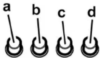
a. BbIKJIouyateJIb OcBeUeHnON/OFF.
b. BbIKJIouaTeIb OFF/ckopoCTb 1
c. IpeeknouaTeNb ckopoctn 2
d. NpeeknouateBb ckopoctn 3
MoJIb c KHOIOHOn NaHeIbIO C 5 KHOKNAM
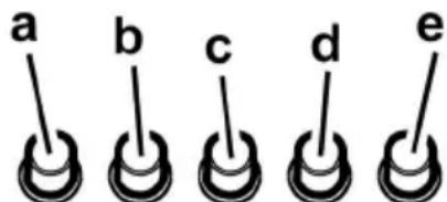
a. BKJI/BbIK noocBETK
b. BblKJI 3neKtpoDburatenei
c.-d.-e.IpOu3BOUHTeINbHOCtB BbITJXKN, MmHmuaJIbHaar (c.), cpeHnra (d.), MaKcMmaJIbHaar (e.).
yxo
BHHMaHHe! PpexJe Yem BbINOHNHT bIO6yO onepaunio no uCTKe nn TexHnueckomy 06cIyXnBaHNO, OTcoEINHHTe BbITAAKKy OT 3JIeKTPocetN, OTcoEINHRA BNkYnnrAIBhBm BblIKNoUaTeJb NOMEuEHN.
OuInCTka
BbTJKa DOnJHn NoDBepraTbcra YactoN OChTKe KaK BHyTpN, TAK N ChapyKn (no KpaHHe Mepe C ToN JKe NepNoDInuHocTbIO, YTO N yXoD 3a QnIbTpAmn DnA 3aDePckKn Knpa). DnA YnCTKn NCNOB3yUte CneuAnbHyO TpRnKy, CMOeHHyO HeITpAlbHbIM XnIDKM MoUoM CpeDCTBOM. He npImeHnTe CpeDCTBa, CoepKaune a6pa3NBhle MaTePnaJIbl.
HE IIPIMEHJNTE CNIPTI
BHHMaHHe: He c6bIIOHe Hne npaBnJ YNCTKn npbOpa n 3aMeHbI pInbTPOB MOKeT npuBeCTn K PnCKy BO3HNKHOBEHnA NOXapa. NToTMy peKOMeHdyem CO6JIIOJaTb npNBedeHHbI e HNCTpyKUnn.
CHMaTeCJIIO6aOTBETCTBEHHOCTbBCB3N CBO3MOXHbIMN IOBpeJDeHNrMM DBrIaTeJI N C NOKapAMN, BO3HKnUHMN BCJeDCTBHe HEnpaBnIbHO rpoMeoHTa NIN Heco6IHOeHNr BBIeONuCaHHbIX PpeDynpEKeJdHn.
ΦnIbTpbl 3aIepKKn Knpa
YdepxnBaet yactnblxnpa,ncxOraune OTnnTbI.
NcnoB3yIte NnB ranoReHOBbie NaMbI Ha 12 BoIbT, MOUHOCTbIO MAKCmym 20 BATT, CdeNaHbE dIg 6a3bI G4, npiroDhbIE dIg NcNoB3OBaHHB OTKpbITbIX CBETNJbHNkax.
CneyuTe yka3aHnMa H He npKacaiTecb K HOBbIM NaMnAm roJbIM pyKaMn.
- 3akpoTe nlafoh (kpeIneHne 3aueKoN).
Ecni CnCTema noCDBeTKe He pa6oTaE, npOBepbTe KoppeKTHyIO yCTaHOBky Iamn B rHe3dax, npexJe Yem O6paNTbcra B ceHTp TEXHueckoi NOMOUI.