
Pro Cut Mulch 'N Catch 51 - Lawn mower Rover - Free user manual and instructions
Find the device manual for free Pro Cut Mulch 'N Catch 51 Rover in PDF.

| Product type | Walk-behind lawn mower |
| Brand | Rover |
| Model | Pro Cut Mulch 'N Catch 51 |
| Cutting width | 508 mm (20 inches) |
| Cutting height adjustments | 12 positions |
| Engine | Petrol engine (type depending on delivery) |
| Fuel | Unleaded petrol |
| Grass bag capacity | Approximately 70 liters |
| Weight | Approximately 35 kg |
| Dimensions (L x W x H) | Not provided by the manufacturer |
| Functions | Mowing, mulching, grass bag collection |
| Cutting system | Single rotary blade |
| Transmission (depending on model) | Self-propelled (optional) |
| Starting | Manual (electric start optional) |
| Safety | Operator presence control, blade brake |
| Maintenance | Clean after each use, chain lubrication, regular blade replacement |
| Spare parts | Available from Rover (blades, belts, filters, etc.) |
| Repairability | Instruction manual provided; assistance from Rover authorized repairer |
| Warranty | Manufacturer's warranty (duration not specified) |
| Included accessories | Grass bag, engine manual, spark plug wrench |
| Available options | Electric start, grass deflector, mulching kit |
Frequently Asked Questions - Pro Cut Mulch 'N Catch 51 Rover
User questions about Pro Cut Mulch 'N Catch 51 Rover
0 question about this device. Answer the ones you know or ask your own.
Ask a new question about this device
Download the instructions for your Lawn mower in PDF format for free! Find your manual Pro Cut Mulch 'N Catch 51 - Rover and take your electronic device back in hand. On this page are published all the documents necessary for the use of your device. Pro Cut Mulch 'N Catch 51 by Rover.
USER MANUAL Pro Cut Mulch 'N Catch 51 Rover
natural_image
Line drawing of a lawn mower with visible blades and wheels (no text or symbols)GB
- Symbols are used on the machine to communicate important information.
• A list of symbols and their meanings are shown below. - Please familiarise yourself with them before operating the machine.
D
Congratulations on your purchase of a quality Australian made and designed product from an Australian owned company.
This manual covers the operation and maintenance of the Rover Walk Behind Powered Lawn Mowers, as listed on the front cover of this manual.

Please read and understand this and any associated manual before using this machine. If any point is unclear, please contact any authorised Rover service dealer.
Symbols
The following symbols have been used in this manual to highlight important information:

This symbol warns against injury to the operator or bystanders.

This symbol warns against mower damage or possible loss of warranty.

This symbol highlights good ideas or tips.
TABLE OF CONTENTS
LABELS ......ii
PREFACE......iii
SAFETY INSTRUCTIONS ....1
COMPONENTS....2
SPECIFICATIONS....2
SETTING UP....2
Assembly of the Grass Catcher
Folding the Handle
Adjusting the Handle Height
Removing the Packaging Ties from the Control Handles
Engine Lubrication and Fuel
Powerstart Option
Self Propelled Option
OPERATION....3
Grass Catcher
- Installing the Grass Catcher
- Removing the Grass Catcher
Mulch Plug
Grass Deflector
Adjusting the Cut Height
Engine
- Starting the Engine
- Stopping the Engine
Grass Cutting and Catching
Self Propelled Option
- Using the Self Propelled Transmission
MAINTENANCE....5
General Cleaning
- Cleaning the Underside of the Mower
- Cleaning the Upperside of the Mower
Changing the Cutting Blades
Self Propelled Option
- Adjusting the Drive Cable
- Removing the Drive Frame Cover
- Replacing the Drive Frame Cover
- Drive Chain Lubrication
- Drive Chain Adjustment
- Drive Belt Adjustment
- Drive Belt Replacement
- Adjusting the Drive Clutches
- Lubricating the Drive Pawls
Powerstart Option
TROUBLE SHOOTING 12
General
Powerstart Option
Self Propelled Option
SPARE PARTS VIEWS....14
Base Spare Parts
Handlebar Spare Parts
Self Propelled Spare Parts
Ancillary Spare Parts
SAFETY INSTRUCTIONS
TRAINING
- Read the instructions carefully. Be familiar with the controls and the proper use of the equipment.
- Never allow children or people unfamiliar with these instructions to use the mower. Local regulations may restrict the age of the operator.
- Never mow while people, especially children, or pets are nearby.
- Keep in mind that the operator or user is responsible for accidents or hazards occurring to other people or their property.
PREPARATION
- While mowing, always wear substantial footwear and long trousers. Do not operate the equipment when barefoot or wearing open sandals.
- Thoroughly inspect the area where the equipment is to be used and remove all stones, sticks, wires, bones and other foreign objects.
- WARNING - Petrol is highly flammable. Take the following precautions:
- Store fuel in containers specially designed for this purpose.
- Refuel outdoors only and do not smoke while refuelling.
- Add fuel before starting the engine. Never remove the cap of the fuel tank or add petrol while the engine is running or when the engine is hot.
- If petrol is spilled, do not attempt to start the engine but move the machine away from the area of spillage and avoid creating any source of ignition until petrol vapours have dissipated.
- For reasons of safety the petrol tank and tank cap lock must be replaced if damaged.
- Replace faulty silencers.
- Before using, always visually inspect to see that the blades, blade bolts and cutter assembly are not worn or damaged.
Replace worn or damaged blades in sets to preserve balance. - On multibladed machines, take care as rotating one blade can cause other blades to rotate.
OPERATION
- Do not operate the engine in a confined space where dangerous carbon monoxide fumes can collect.
• Mow only in daylight or in good artificial light. - Avoid operating the equipment in wet grass, where feasible.
• Always be sure of your footing on slopes. - Walk, never run.
- For wheeled rotary machines, mow across the face of slopes, never up and down.
• Exercise extreme caution when changing direction on slopes. - Do not mow excessively steep slopes.
- Use extreme caution when reversing or pulling the mower towards you.
- Stop the blade(s) if the mower has to be tilted for transportation when crossing surfaces other than grass and when transporting the mower to and from the area to be mowed.
- Never operate the mower with defective guards or shields, or without safety devices, for example deflectors and/or grass catchers in place.
- Do not change the engine governor settings or overspeed the engine.
- Disengage all blade and drive clutches before starting the engine.
- Start the engine or switch on the mower carefully according to instructions and with feet well away from the blade(s).
- Do not tilt when starting the engine or switching on the motor, unless the mower has to be tilted for starting. In this case, do not tilt it more than absolutely necessary and lift only the part which is away from the operator.
- Do not start the engine when standing in front of the discharge chute.
- Do not put hands or feet near or under rotating parts. Keep clear of the discharge opening at all times.
- Never pick up or carry a mower while the engine is running.
- Stop the engine and disconnect the spark plug lead:
- Before clearing blockages or unclogging the chute.
- Before checking, cleaning or working on the mower.
- After striking a foreign object. Inspect the mower for damage and make repairs before restarting and operating the mower.
- If the mower starts to vibrate abnormally check immediately.
- Stop the engine:
- Whenever you leave the mower.
- Before refuelling.
- Reduce the throttle setting during engine run-out and if the engine is provided with a shut-off valve, turn off the fuel at the conclusion of mowing.
MAINTENANCE AND STORAGE
- Keep all nuts, bolts, and screws tight to be sure the equipment is in safe working condition.
- Never store the equipment with petrol in the tank inside a building where fumes may reach an open flame or spark.
- Allow the engine to cool before storing in any enclosure.
• To reduce the fire hazard, keep the engine, silencer, battery compartment and petrol storage area free of grass, leaves, or excessive grease. - Check the grass catcher frequently for wear or deterioration.
- Replace worn or damaged parts for safety.
- If the fuel tank has to be drained, do this outdoors.

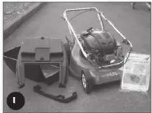
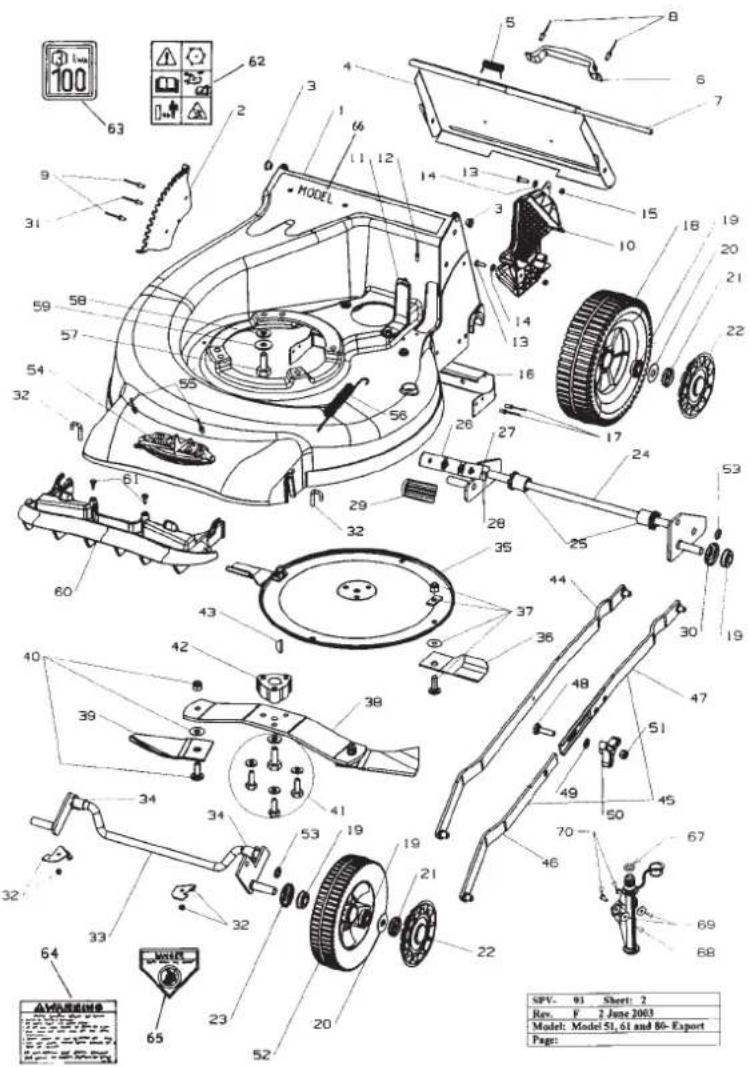
COMPONENTS
- ensure that all the following component parts are included in the package (refer figure 1):
- Mower (1 off)
- <it including: Owners Manual (1 of)
:engine Manual (1 of)
Spark Plug Spanner (1 of
Screw - 3/16" x 1/2" UNC (2 of
Vyloc nut - 3/16" UNC (2 of)
Washer - 3/16" x 1/2" flat (2 of
- Grass catcher bottom (1 of)
- Grass catcher top (1 of)
- Grass catcher handle (1 of - may be loose or fitted to Grass catcher top)
NB. Other accessories may be included in the carton which vary with each model. These items will be covered by a separate owners manual e.g. Mulch Mowing Kit, Grass Deflector Kit, etc
- Notify the place of purchase of missing items as soon as possible.
SPECIFICATIONS
• This manual covers several mowers with the following specifications
- Models 51, 6'
- 20" (508mm Cut Width
- 12 Cut Height Setting:
- Model 80
-22" (560mm Cut Width
- 15 Cut Height Setting:
NR. - Models come with one of a range of engines (refer to the engine manual included in the kit).
- Options are available (and may be included) on the above models e.g
- Mulch Mowing
- Deflector Mowing
- Remote Air Cleaner
- Powerstart Function
- Self Propelled Function
-etc.
- Details may be included in this manual or on a separate manual included in the Mower Kit
SETTING UP
• Before using the Mower the following set-ups are required
ASSEMBLY OF THE GRASS CATCHER
- Locate the catcher handle and align its front lugs with the slots in the top of the catcher and press firmly into position (refer figure 2).
- Position the catcher top over the catcher bottom, aligning the barbs on the top with the slots in the bottom (refer figure 2).
- Press firmly down on the catcher top to lock the barbs into slots (refer figure 2).
- Secure the top and bottom halves of the grass catcher together at the front using the two 3/16" screws, washers and nyloc nuts supplied. Insert the screws from the outside with the washers and nyloc nuts on the inside of the catcher
FOLDING THE HANDLE
- Locking knobs: by turning these knobs the handle bars can be either locked in the operating position or folded for storage.
- Locking lever: lift the lever to release the handle bars for folding or push the lever closed to lock handle bars in the operating position. Adjust the tension by turning the lock nut with a 1/2" AF spanner (reler figure 4 A)

Before unfolding the handlebar, ensure the throttle control is in the stopped position (see "Starting the Engine" section) and activate the operator presence control lever (refer figure 3). Lift the handlebar slowly (as the engine start cord is attached and it will crank the engine) until the fully erect position is achieved
ADJUSTING THE HANDLE HEIGHT
- Loosen the two nuts (B) at the base of the handle bars on both sides of the mower using a 1/2" AF spanner (refer figure 4).
- Move the handle bars to the required position and tighten the handle bar nuts.
natural_image
Black-and-white photo of a small vehicle with internal components and a box on the ground (no visible text or symbols)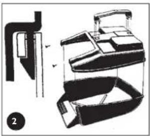
natural_image
Technical line drawing of a mechanical device with exploded view and assembled views (no text or symbols)
natural_image
Line drawing of a mechanical lever or bracket with a curved handle and mounting feet (no text or symbols)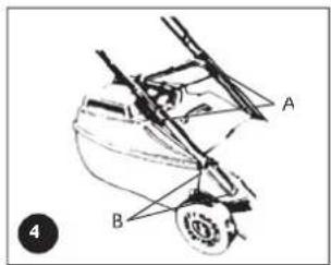
SETTING UP (Continued)
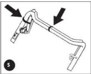
REMOVING THE PACKAGING TIES FROM THE CONTROL HANDLES

Remove and discard the packaging ties clamping the blade brake and self propelled drive control bale to the handle bar before attempting to start the mower (refer figure 5).
- Unfold the handlebars and lock in the erect position (refer to the "Folding the Handlebar" section).
- Remove the packaging ties (refer figure 5).
natural_image
Mechanical linkage diagram showing two connected components with arrows indicating motion direction (no text or symbols)ENGINE LUBRICATION AND FUEL

The engine safety precautions, oil and fuel recommendations, operation instructions, adjustments and maintenance is covered in the engine manufacturer's manual which is included in the mower kit. Please refer to and adhere to these recommendations.
If you do not have the engine manufacturer's manual please refer to the nearest engine manufacturer's representative for a replacement copy.
The engine is packed without oil or fuel. Please add these as per the engine manufacturer's recommendations before attempting to start the engine.
Do not allow any dirt or contaminants to enter the fuel tank or oil filler tube.
POWERSTART OPTION
The battery must be removed from the mower while recharging.
Only use the battery charger indoors where it cannot be affected by weather.

The battery contains a strong acid electrolyte which may cause personal and material damage.
- Do not disassemble, drop or damage the battery.
- Do not incinerate or expose the battery to high heat or a flame or it may explode.
- Dispose of batteries thoughtfully. Refer to your local regulations for battery disposal.
- Replace any leaking battery immediately.
- Clean the battery only with a dry cloth - never use petrol, thinners or other petrochemical.
- Neutralize any electrolyte spills with an alkaline solution.
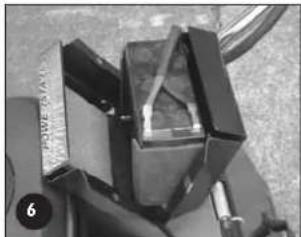
- Remove the two screws from the battery support box, rotate the battery and lid forward and expose the battery terminals (refer figure 6).
- Slide the red and black wire from the battery terminals and remove the battery.
- Place the battery in a dry, cool area and connect the battery charger cables to the battery terminals (red [+] to red [+] and black [-] to black [-]).
- Connect the battery charger to a 220-240 volt power outlet and switch it on.
- Allow to charge for 10-16 hours, switch the 220-240 volt power outlet off and remove the battery charger cables from the battery.
- Refit the rubber battery blocks to each end of the battery and refit into the battery support box.
- Slide the wiring loom connections onto the battery terminals red [+ ] to red [+ ] and black [-] to black [-] .
- Locate the battery support box lid, refit and tighten the two screws.
natural_image
Close-up of mechanical components with no visible text or symbolsSELF PROPELLED OPTION

Remove and discard the packaging tie clamping the self propelled drive control bale to the handle bar before attempting to start the mower (refer figure 5).
OPERATION

- Refer to and follow the "Safety Instructions" in this and any other associated manuals supplied with this product before attempting to operate this machine.
- Refer to and understand the safety symbols fitted to the machine and shown in the "Labels" section of this manual.
- Ensure that all the items in the "Setting Up" section have been completed.
- Ensure that the "Operator Presence Control" functions correctly. This control is a mandatory safety item and operates a brake on the engine. When the lever is held against the handlebar the brake is released and the blades/engine are free to rotate. When the lever is released the brake is applied and the blades/engine brake quickly to a stop
GRASS CATCHER

- Never install or remove the Grass catcher with the engine running.
OPERATION (Continued)
Installing the Grass catcher
- Raise the rear flap of the mower.
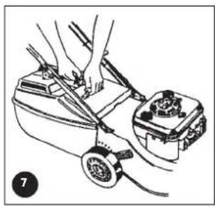
- Grasp the grass catcher by the top handle and position the grass catcher against the rear of the mower (refer figure 7).
- Lower the rear flap so that the back edge of the flap hooks over the matching lip on the grass catcher.
Removing the Grass catcher
- Grasp the grass catcher top handle and lift up.
- Raise the rear flap of the mower to release grass catcher.
- Lift the grass catcher clear of the mower and lower the rear flap.
MULCH PLUG
• Refer to the separate Mulch 'n' Catch Owners Manual.
GRASS DEFLECTOR
• Refer to the separate Grass Deflector Owners Manual.
ADJUSTING THE CUT HEIGHT

- When setting the cut height stand to the rear of the machine with your feet well clear of the cutting blades.
- Grasp the height of cut lever (A) and apply an outward pressure to release the lever from the rack (B) (refer figure 8).
- Move the lever (while holding out) to the required height of cut position and engage the lever in the rack.
- Pushing the lever forward and down raises the cut height and vice versa.
natural_image
Illustration of hands using a tool to adjust or install a mechanical device (no text or symbols visible)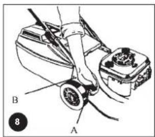

It is advisable to start the mower in the high cut position and gradually drop the height notch by notch until the desired height is achieved. Starting too low will leave a low spot in the lawn.
ENGINE
NOTE: The mowers covered in this manual have various engine types from various manufacturers. Included in the Mower Kit is an engine manual specific to each mower which provides the details for the engine's operation. Please refer to the engine manufacturer's manual for precise instructions.
Starting the Engine

- The engine safety precautions, oil and fuel recommendations, operation instructions, adjustments and maintenance is covered in the engine manufacturer's manual which is included in the mower kit. Please refer to and adhere to these recommendations.
- If you do not have the engine manufacturer's manual please refer to the nearest engine manufacturer's representative for a replacement copy.
- The engine is packed without oil or fuel. Please add these as per the engine manufacturer's recommendations before attempting to start the engine.
- If fitted with the Powerstart option activate the operator presence control lever (to release the blade brake) before attempting to crank the engine.

- Refer to the "Warning" notes at the beginning of the "Operation" section.
- Start the mower on a clear level surface.
- Keep your fingers, toes and bystanders clear when starting or operating the engine.
-
If fitted with the Powerstart option, always remove the key from the ignition switch and keep in a safe place to prevent unauthorised cranking of the engine.
-
Refer to the engine manufacturer's manual for the starting procedure, remembering to activate the operator presence control lever before cranking the engine.
- If fitted with the Powerstart option, insert the key into the ignition switch then follow the instructions in the engine manufacturer's manual.

The Rover throttle control uses symbols to indicate the throttle function at various throttle positions:
0 (off), (slow speed), (fast speed), (engine choke)
These positions align with settings required in the engine manufacturer's manual.
The Rover Powerstart option can be started with an ignition key which is fitted to the handle bar. The switch plate uses symbols to indicate the key function at various positions and refers to the state of the starter motor:
0 (off), I (on/start). These positions align with the settings required in the engine manufacturer's manual.
Stopping the Engine
- Refer to the engine manufacturer's manual for stopping procedure.
- If fitted with the Powerstart option remove the ignition key and store in a safe place after use.
OPERATION (Continued)
GRASS CUTTING AND CATCHING

Refer to and abide to the instructions noted in the safety instructions of this and associated manuals.
- Fit the Grass catcher to the mower (refer to the "Setting Up" section).
- Start the engine and set the engine speed to fast ( ) on the throttle control.
- Set the desired cut height (refer to "Setting the Cut Height" above).
- Drive the mower forward through the grass until the catcher fills.
- Stop the engine, remove and empty the catcher.
- Repeat the process.

- To maximise the cutting and catching performance it is important to maintain high engine speed, so adjust the mower ground speed to suit.
- If the grass length or density is excessive (to maintain high engine speed initially) cut the grass at a higher setting, then at the desired height.
- Replace blades regularly to maintain a sharp cutting edge.
- Keep the mesh in the grass catcher clean to allow the grass catcher to fill properly.
- Keep the underside of the mower deck clean and free of clipping build-up.
SELF PROPELLED OPTION
Using the Self Propelled Transmission
- Start the engine and set the engine speed to fast.
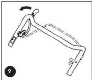
- Push forward on the clutch engagement lever to engage the self-propelled drive to the rear wheels noting that the drive speed increases as you move the bale closer to the handle bar (refer figure 9).
- Hold the bale at the required drive speed and slow down or speed up as the conditions dictate.
• To disengage the self-propelled drive release the engagement lever and allow it to return to the disengaged position.

Release the self-propelled drive bale and push the machine when changing direction or mowing in a confined area for safety.
natural_image
Line drawing of a mechanical lever mechanism with a curved arrow indicating rotational motion (no text or symbols)MAINTENANCE
NOTE: The majority of mower problems involve the following problems:
- Dirt or contaminants in the fuel
- Incorrect oil level in the engine
- Blocked, damaged or incorrectly fitted air cleaner
- Incorrectly maintained blades
(Refer to the maintenance section of this and the engine manufacturer's manual for details.)

• Always ensure equipment is in good working order.
- Do not use any equipment with worn or damaged components.
• Always use genuine Rover replacement parts.
- Never attempt maintenance that is not outlined in this manual. Refer to your nearest authorised Rover Service Dealer.
• Always ensure the engine is stopped and remove the spark plug wire before attempting any maintenance on the mower.
- On Powerstart models remove the key from the ignition before attempting any maintenance on the mower.
- All safety guards, blades, grass catchers and safety labelling must be replaced with genuine Rover parts if worn or damaged.
• Always replace blades and blade fixings in complete sets to maintain balance.
- Remove clipping build-up around the muffler area to prevent a fire hazard.

• Refer to and abide to engine manufacturer's manual.
- Do not allow any dirt or contaminants to enter the fuel tank, oil filler tube, air cleaner housing, carburettor or spark plug hole when maintaining the engine.
- Ensure there is no clipping build-up in the vents adjacent to the recoil starter. The engine may overheat and be damaged if these vents are not clear.
- Do not use high pressure cleaners to wash the machine and keep water away from the engine and electrical components.
- If tilting the mower, the engine spark plug must remain uppermost to prevent oil seepage into the air cleaner and/or exhaust.
• To prevent fuel leaking from the tank when tilting the mower ensure the fuel level is low or empty.
- Ensure the mower is dry and clean and stored in a well ventilated area.
MAINTENANCE (Continued)
GENERAL CLEANING

• Refer to the general "Warning" and "Caution" notes at the beginning of this section
- Never open the discharge flap, or lift the mower to wash the underside of the deck with the engine running.
- To ensure safe operation and long life it is recommended to clean the mower after every use. This will prevent corrosion, overheating and fire risk while ensuring ultimate performance.
Cleaning the Underside of the Mower
- Place the mower outdoors on a flat surface.
- Set the cut height to maximum.
- With the engine stopped, remove the grass catcher and lift open the discharge flap.
• Use a garden hose to wash out all the grass clippings. - Inspect the underside and repeat the cycle if still not clean.
Mowers fitted with optional washport refer to page 10.
Cleaning the Upperside of the Mower
- Use a dry rag or soft brush to remove all loose clippings.
- Use a damp rag with mild detergent to clean away oil or other grime
- Wash the grass catcher separately from the mower with a hose washing all clippings out of the inside, outside and from the grass catcher mesh.
- Let the mower dry before storing.
CHANGING THE CUTTING BLADES

Refer to the "Warning" and "Caution" notes at the beginning of this section.
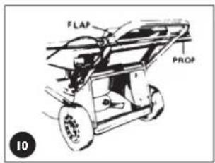
- With the engine stopped, spark plug wire and grass catcher removed, open the discharge flap and prop in the open position (reler figure 10).
- Set the mower to high cut and fold the upper handle bar down.
- Rotate the cutting assembly carefully to access the blade retaining bolts.
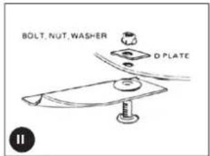
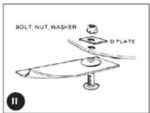
• Using gloves and a suitable spanner, remove the blade assembly - Retain the 'D' plates (where fitted) and discard the blades and fasteners.
- it the new blades and lasten in the correct order (refer figure 11)
• Lighten the blade retaining nuts firmly (16Nm) - Remove the flap prop, close the discharge flap and refit the spare plug wire.

- Remove all clipping build up from around the blade retaining nuts before fitting the spanner.
- Jse a ring or socket spanner to prevent slipping off or damaging the blade retaining nut.
• The blade should be free to rotate if the bolts are fitted correctly.
SELF PROPELLED OPTION

Refer to the "Warning" and "Caution" notes at the beginning of the maintenance section.
Adjusting the Drive Cable

If cable adjustment is necessary ensure that the drive disengages before starting the mower or it may drive off unattended. This can be checked by pulling the mower backwards (with the drive bale released) - the rear wheels should free wheel

- Do not overtighten the cable assembly.
- Should the transmission continue to slip after adjustment, have the mower serviced by an authorised Rover dealer
MAINTENANCE (Continued)
Adjusting the Drive Cable (Continued)
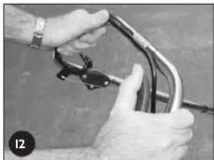
- Start the mower in the disengaged position.
- Push the drive bale forward until the gap between the bale and the handle bar is 55mm (refer figure 12).
• The drive should just begin to engage at this point. - If the drive is not beginning to engage, rotate the thumb wheel on the cable support block (one click at a time) in an anti-clockwise direction until it does (refer figure 13).
- If the drive engages and drives off at a gap greater than 55mm rotate the thumb wheel on the cable support block one click at a time in the clockwise direction until it does (refer figure 13).
- Test the mower at all speeds ensuring that it self disengages when the drive bale is released and that the transmission does not slip at full speed with the drive bale fully engaged.
- If you still experience problems, see your nearest authorised Rover dealer.

- Ensure the cable is not damaged or kinked which may affect the drive.
- Apply a drop of lubricant to the pivot points of the drive bale to ensure smooth and safe operation.
natural_image
Close-up of hands holding a bicycle tire and chain (no visible text or symbols)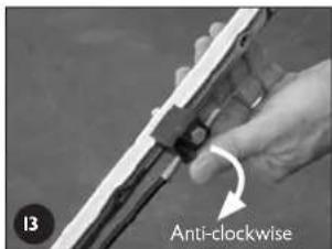
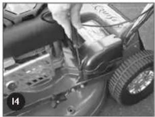
Removing the Drive Frame Cover
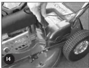
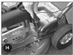
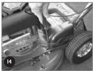
- Unscrew the front and rear phillips head screw in that order (refer figure 14).
- Lift the cover and rotate out of the mower to expose the upper transmission components.

Blow grass and dirt out of the recessed holes to expose the head of the fixings.
natural_image
Close-up of a car tire being adjusted for a tool, no visible text or symbolsReplacing the Drive Frame Cover

- Make sure the raised ring on the brass section of the drive cable nests into the groove of the lower drive support frame and fit the lid accurately on top before screwing down the cover.
-
Do not operate the transmission bale with the cover loose or removed as you will damage the lower drive support frame.
-
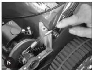
Fit the drive cable into its retaining slot in the lower drive support frame and hold it down horizontally with one hand (refer figure 15).
- Rotate the cover into position over the cable until it seats properly and maintain pressure on the lid above the cable.
- Screw the rear fixing above the cable down firmly.
- Screw the forward fixing down firmly.

Leave the fixings in the lid when removing or replacing.
natural_image
Close-up of a hand using a tool to adjust or install a mechanical component (no visible text or symbols)Drive Chain Lubrication

- Refer to the "Warning" and "Caution" notes at the beginning of the maintenance section.
- Do not apply excessive lubricant to the chain as it may flick off and onto the drive clutches during operation.
-
Keep lubricant clear of the drive clutches.
-
Remove the drive frame cover (refer to the "Removing the Drive Frame Cover" section) to expose the drive chain.
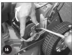
- While rotating the outer clutch plate (clockwise) apply an even spread of suitable (non aerosol) chain lubricant along the length of the chain (refer figure 16).
- Replace the drive frame cover (refer to the "Replacing the Drive Frame Cover" section).

Put the chain lubricant in a container with a long pointed spout to make application easier. Apply a little of the lubricant on the cams between the clutch engagement lever and the outboard output shaft bearing retainer while lubricating the chain.
natural_image
Close-up of hands adjusting a mechanical component with a tool (no visible text or symbols)MAINTENANCE (Continued)
Drive Chain Adjustment

- Refer to the "Warning" and "Caution" notes at the beginning of the maintenance section.
- Keep the chain correctly tensioned to prevent damage or abnormal wear.
- Do not over tension the chain.

- Ensure the engine and muffler are cold before attempting to adjust the chain to prevent burns.
- Remove the drive frame cover (refer to the "Removing the Drive Frame Cover" section) and expose the drive chain.
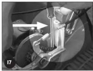
• Using a long slender shaft press firmly on the chain as far from the top sprocket as possible (refer figure 17). - Using a suitable Phillips head screw driver rotate the adjusting screw until the chain deflection (above) is 5mm (refer figure 18).
- Rotate the outer clutch plate (chain), recheck chain deflection and re-adjust if necessary.
- Replace the drive frame cover (refer to the "Replacing the Drive Frame Cover" section).

- Rotate the chain adjustment screw clockwise (when looking directly at the head of the screw) to tighten the chain tension and vice versa.
- Use a very long, or right angle single drive phillips head screw driver to better access the chain adjusting screw.
- Check the condition of the chain joiner and sprocket and replace if necessary.
Drive Belt Adjustment

- Refer to the "Warning" and "Caution" notes at the beginning of the maintenance section.
- Do not over or under tension the belt to prevent damage or abnormal wear.
- Remove the drive frame cover (refer to the "Removing the Drive Frame Cover" section) and expose the belt adjustment screw (refer figure 19).
• Using a suitable phillips head screw driver, screw the adjuster screw down carefully until the spring is fully compressed. - Unscrew the adjuster two (2) full turns.
- Rock the gear box about the output shaft and it should move approximately 2mm under the spring load (refer figure 20).
- Replace the drive frame cover (refer to the "Replacing the Drive Frame Cover" section).

- Clean any clippings away from the underside of the gearbox near the adjusting spring before adjusting the belt tension.
- Put a mark on one side of the screw head of the adjuster to easily identify the 2 full turns when adjusting the belt tension.
Drive Belt Replacement

- Refer to the "Warning" and "Caution" notes at the beginning of the maintenance section.
- Refer to the "Caution" notes in the "Belt Adjustment" section.

• Always wear gloves when handling the cutting mechanism.
- Wear gloves and be aware of pinch points when handling the drive belt mechanism.
- Secure the mower safely when tilted upwards to access the underside.
- Place the rear wheels on support blocks so that the rear extension guard will clear the ground when lifting the front of the mower up. This will prevent damage to the guard which is a mandatory safety item.
- Remove the drive frame cover (refer to the "Removing the Drive Frame Cover" section).
- Unscrew the drive belt adjustment screw until the spring touches the underside of the gearbox housing (refer figure 21).
- Fold the handle bars down and remove the grass catcher and support the rear wheels above the ground on 50mm (min) blocks.
- Lift the front of the mower about the rear wheels until the lower handle bar contacts the ground and secure safely in this position.
- Rotate the cutting assembly to expose the two bolts which fix the belt cover (refer figure 22).
- Using a suitable spanner, remove both bolts and washers and remove the belt cover.
- Rotate the gearbox so its pulley is as close to the engine pulley as possible. Rotate the belt off the gearbox pulley and discard the belt.
natural_image
Mechanical assembly diagram showing a bracket and wheel assembly with an arrow indicating motion direction (no text or symbols)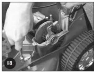
natural_image
Close-up of a hand adjusting a mechanical component with tools and a tire (no visible text or symbols)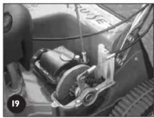
natural_image
Close-up of a car's front wheel assembly with visible mechanical components (no text or symbols)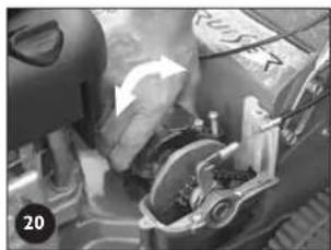
natural_image
Close-up of a mechanical assembly with a hand operating a component, no visible text or symbols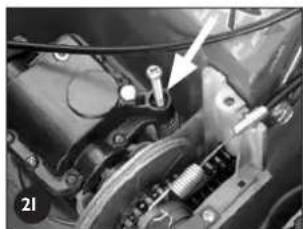
natural_image
Close-up mechanical assembly showing a bracket and spring mechanism (no visible text or symbols)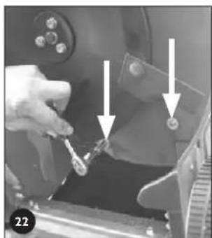
natural_image
Close-up of a hand holding a small object with arrows pointing to a component, no visible text or symbolsMAINTENANCE (Continued)
Drive Belt Replacement (Continued)
- Only if the mower is fitted with a full disc and blades will it be necessary to remove the cutting assembly by undoing the centre bolt and three surrounding bolts with suitable spanners.
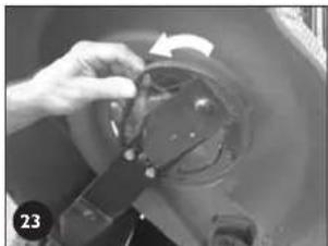
- If the mower is fitted with the "Inline Swing Back Blade" option, rotate both blades backward until the flute on the blade touches the blade support bar (see figure 23).
- Fit the new belt on the engine pulley, rotate the gearbox so its pulley is as close to the engine pulley as possible. Rotate the belt into the gearbox pulley groove.
- Adjust the drive belt adjustment screw (refer to the "Drive Belt Adjustment" section.)
- Replace the belt cover, flat washers and bolts and tighten firmly.
- Replace the cutting assembly (where required) and fit the centre bolt and washer and the three surrounding bolts and washers loosely before tightening in the following sequence and tensions - centre bolt (65-70 Nm) and three surrounding bolts (16-19Nm)
- If the mower is fitted with the "Inline Swing Back Blade" option, rotate the blades back so they are in line with the blade support bar.
- Lower the mower so all wheels rest on the ground.
- Replace the drive frame cover (refer to the "Replacing the Drive Frame Cover" section).

- Clean the clipping buildup off the heads of the bolts of the belt cover fixings to ensure the spanner fits correctly.
- Clean out the belt cover and transmission area thoroughly before reassembly.
- Inspect the drive pulleys for wear, damage and make sure they are not loose while the belt is removed. Replace as required.
- Special belts and pulleys are used for long life and accurate fitment, so replace with genuine Rover products.
Adjusting the Drive Clutches
Note: This procedure is only necessary should the drive cable adjustment not be able to provide sufficient drive. This adjustment is to allow for wear on the drive plates in the long term.

- Refer to the "Warning" and "Caution" notes at the beginning of the maintenance section.
- Remove the drive frame cover (refer to the "Removing the Drive Frame Cover" section) to expose the drive clutch plates and other adjustments.
- Loosen the drive chain fully by unscrewing the chain adjuster (refer figure 24).
- Loosen the drive belt fully by unscrewing the drive belt adjuster (refer figure 25).
- Using a suitable Allen key, remove the centre fixing and thrust washer from the end of the output shaft (refer figure 26).
- Remove the two fixings retaining the outboard output shaft bearing housing (refer figure 27).
- Lift the outer end of the output shaft slightly and slide off the outboard output shaft bearing retainer (refer figure 28).
• Take note of which marking (on the boss of the inner drive plate) aligns with the end of the locking roll pin (through the output shaft) (refer figure 29). - Move the drive plates and actuating cam in an outboard direction until the inner drive plate is free of the roll pin (refer figure 29).
- Rotate the inner driver plate until the roll pin aligns with the marking with ONE extra groove than that originally noted above. Slide back to lock the drive plate to the roll pin into its new position.
- Replace the outer output shaft bearing retainer and screw down firmly in position.
- Replace the centre fixing and thrust washer on the end of the output shaft, apply thread locking solution to the centre fixing and tighten firmly.
- Readjust the drive chain (refer to the "Drive Chain Adjustment" section).
- Readjust the drive belt (refer to the "Drive Belt Adjustment" section).
- Replace the drive frame cover (refer to the "Replacing Drive Frame Cover" section).
- Re-adjust the clutch cable (refer to the "Adjusting the Drive Cable" section).

- The marks on the inner drive plate boss represents positions 'I', 'II', & 'III'. Setting 'I' is generally used with a new drive plate whereas position 'III' is for a worn unit.
- If the drive cable adjustment is insufficient with the inner drive plate in position 'III' the drive plates must be replaced.
- Clean off and apply new grease to the cams of the outboard output shaft bearing retainer and cam lever before reassembly.
natural_image
Close-up of a hand adjusting a mechanical component with a circular component and a curved arrow (no visible text or symbols)
natural_image
Close-up of a hand adjusting a mechanical component with an arrow pointing to a tire (no visible text or symbols)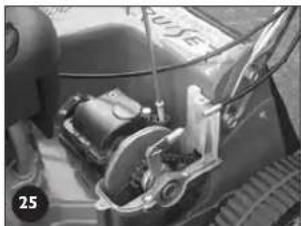
natural_image
Close-up of a mechanical device with visible components and no readable text or symbols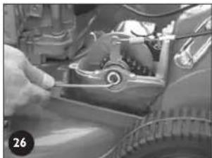
natural_image
Close-up of a hand adjusting a mechanical component with visible gears and springs (no text or symbols)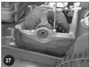
natural_image
Close-up of a mechanical component with visible gears and housing (no text or symbols)
natural_image
Close-up of hands assembling or inspecting a mechanical component (no visible text or symbols)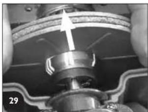
natural_image
Close-up of a mechanical assembly with a metallic component and a white arrow indicating direction (no visible text or symbols)MAINTENANCE (Continued)
Lubricating the Drive Pawls
• Support the rear wheels off the ground.
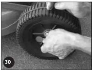
- Remove the rear hubcaps and wheel plugs (refer figure 30).
- Inspect the inside of the wheel hub through the wheel plug hole. If dirt is found, the wheel should be removed and cleaned.
• To remove the wheel, remove the ratchet plate securing the wheel to the axle.
- Withdraw the wheel from the axle and clean out thoroughly.
- Using clean engine oil, apply a few drops of oil to the end of the drive gear above the retaining washer and rotate the gear to allow the oil to penetrate (refer figure 31). The gear should rotate freely, if not, repeat the above procedure.
- Replace the wheel, washer and secure with a new ratchet plate.
- If the wheel hub is clean, rotate the wheel until the drive gear is visible through the wheel plug hole.
- Using clean engine oil, apply a few drops of oil to the end of the drive gear (as above) and rotate the wheel one or two times to allow the oil to penetrate. The wheel should rotate freely, if not repeat the procedure (refer figure 31).
- Replace the wheel plugs and the hubcaps.

- Use a thin bladed screwdriver or similar between the hubcap and the wheel to prise off the hubcap, being careful not to over bend it.
- Ratchet plates require special tools to remove and replace them. If you are unsure, contact your nearest authorized Rover dealer.
• Purchase new ratchet plates before removing the wheels as they are not reusable.
natural_image
Close-up of a hand adjusting a tire with a tool, no visible text or symbols
natural_image
Close-up of a tire with a metal rod inserted, showing tread pattern and central hub (no text or symbols visible)POWERSTART OPTION
N.B. The battery maintenance details are covered in the setting up section and the following matrix.

- Refer to the "Warning" and "Caution" notes at the beginning of this section.

Keep battery fully charged to ensure maximum service life.
Mower cleaning using optional washport
- Place the mower outdoors on a flat surface.
- Set the cut height to high cut position.
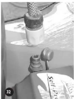
- With the engine stopped connect a garden hose with a snap on connection (remove the cap first), to the washport fitted to the inside face of the cutting chamber. (refer figure 32.)
- Turn the garden hose on.
- Return to the mower and start the engine and run at full speed for 1 minute.
- Stop the engine and turn off the garden hose.
- Remove the garden hose from the washport and replace the cap.
- Inspect the underside of the mower, if not completely clean use the garden hose to flush out the remaining debris.
natural_image
Close-up of a mechanical component with a threaded fitting and a labeled part (no readable text or symbols)MAINTENANCE (Continued)
| Components | Action | Before Mowing | After Mowing | While Mowing | Every 5 hours | Every 25 hours | Special Considerations |
| Overall mower Clean the upper and underside | ● | ||||||
| Engine air cleaner elements | Visually inspect and clean | ● | instructions. | Refer to the engine manufacturer's manual for | |||
| Engine oil | Check level | ●instructions. | Refer to the engine manufacturer's manual for | ||||
| Engine oil | Replace | instructions. | Refer to the engine manufacturer's manual for | ||||
| Engine spark plug | Inspect and clean | instructions. | Refer to the engine manufacturer's manual for | ||||
| Engine general | Inspect and clean | ●instructions. | Refer to the engine manufacturer's manual for | ||||
| Throttle cable Inspect and lubricate | damaged. | ● | Oil inner cable if tight. Replace if kinked or | ||||
| Operator presence control | Check the blade brake stops the engine when the lever is released | ● | Have the engine serviced by an authorised service agent if in doubt or not functioning. | ||||
| Lubricate the lever pivots | ● | ||||||
| Cutting blades | Inspect | ●is out of balance. | Replace if worn, bent, damaged or if the assembly | ||||
| Drive cable (where fitted) Adjustment | Inspect for damage or kinks | ● | Replace if necessary. | ||||
| ● | ● | ||||||
| Drive assembly under drive frame cover (where fitted) | Inspect and clean | ● | |||||
| Drive chain (where fitted) Adjustment | Lubrication | Every 100 hours. | Every 50 hours. | ||||
| Drive belt (where fitted) Adjustment | ● | ● | Replace belt if adjustment procedure does not | ||||
| restore full drive | |||||||
| Drive Belt Cover | Remove, clean and inspect | Every 50 hours. | |||||
| Drive Pawls (where fitted) | Inspect, clean, lubricate | ● | In boggy conditions inspect more regularly and clean and lubricate as required. | ||||
| Guards and safety labels | Inspect and clean | ● | Replace before next mowing. | ||||
| Battery (where fitted) Recharging | Inspect and clean | ● | Make sure the battery is firmly supported in the support box.As required but mainly after long periods of non use. | ||||
| Key switch (where fitted) | Inspect | ● | Replace if damaged. | ||||
| Wiring loom (where fitted) | Inspect | ● | Replace if damaged. | ||||
TROUBLESHOOTING
GENERAL

- Never attempt any corrective action that is not outlined in this or associated manuals. Refer to your nearest authorised Rover dealer. - Always replace components with genuine Rover replacement parts.

- Use the associated engine manufacturers manual for engine related trouble shooting and corrective action instructions.
- Refer to the relevant sections in this manual for corrective action instruction.
- Other manuals maybe included with your mower, which may relate to specific options of the mower. Use these manuals for specific trouble shooting related to the options.
| Problem Possible Causes Corrective Action | ||
| Engine won't start • Fuel supply | Fill the fuel tank*Prime the fuel system*Turn the fuel tap on (where fitted)*Drain and replace, stale or contaminated fuel*Move throttle or choke or fast positionRe-adjust throttle control cable*Have the engine serviced by an authorised service agent | |
| Air cleanerClean or replace air filter*Spark PlugClean/adjust/replace spark plug*Refit the spark plug wireHave the engine serviced by an authorised service agent | ||
| Operator presence controlActivate operator presence controlReconnect/replace disconnected/broken cableHave the engine brake serviced by an authorised service agent | ||
| Uneven Grass Cutting | Blades are blunt/worn/bent | Replace blades |
| Engine speed is too slow | Use full engine speed | |
| Cut height is too low | Raise cut height | |
| Ground speed is too fast | Slow down the ground speed | |
| Clippings drop while grass catching | Refer to “Uneven Grass Cutting” section items | Refer to “Uneven Grass Cutting” section items |
| Grass catcher is full | Empty the grass catcher | |
| Grass catcher mesh/vents are dirty/blocked | Clean the mesh/vents to allow maximum air flow | |
| Grass catcher is damaged | Replace the grass catcher | |
*Denotes: Refer to the engine manufacturer's manual for details and instructions.
POWERSTART OPTION
| Problem Possible Causes Corrective Action | ||
| Engine cranks slowlyBad electrical connectionsFaulty/flat battery | Reconnect connections securelyReplace faulty electrical cablesReplace/recharge the batteryRefer to “Engine Cranks Slowly” section itemsReplace the key switchHave the engine serviced at an authorised service dealerActivate operator presence controlReconnect/replace disconnected/broken cableHave the engine brake serviced by an authorised service agent | |
| Engine won’t crankRefer to “Engine Cranks Slowly” section itemsFaulty key switchFaulty starter motor on the engineOperator presence control | ||
SELF PROPELLED OPTION
| Problem Possible Causes Corrective Action | ||
| Transmission slips under load | Drive cable damaged/disconnected/not adjusted correctlyNo adjustment left in the drive cableDrive clutches damaged or wornSlipping drive belt | Replace/reconnect/adjust drive cablesAdjust drive clutchesReplace drive cableReplace drive platesReadjust or replace the drive beltsReplace worn drive pulleyReplace broken belt tensioning spring |
| Transmission doesn’t drive | Refer to “Transmission Slips Under Load” section itemsGearbox is damaged or seizedClutch Plate drive pin is brokenFinal drive sprocket roll pin is brokenBroken/dislodged drive chainBroken/dislodged drive beltEngine drive pulley key brokenGear box pulley roll pin brokenPinion gears/pawls in the drive wheels broken/worn | Refer to “Transmission Slips Under Load” section itemsReplace gearboxReplace roll pinReplace roll pinReplace/refit drive chainReplace/refit drive beltReplace key in drive pulleyReplace roll pinReplace broken/worn components |
| Mower doesn’t free wheel easily when drive is in neutral | Rear wheels jammed with foreign materialPawls in the rear wheels are damaged or seizedBearings in wheels are seized. | Clean out and re-lubricate rear wheelsReplace or re-lubricate the pawlsReplace wheels bearings |
VORWORT
natural_image
Black-and-white photo of a damaged vehicle with broken body and debris, no visible text or symbols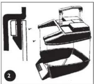
natural_image
Technical line drawing of a mechanical device with exploded view and internal components (no text or symbols)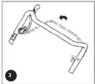
natural_image
Line drawing of a mechanical bracket with a curved handle and mounting feet (no text or symbols)
VORBEREITUNGEN
natural_image
Mechanical linkage diagram showing two arms with arrows indicating movement or force direction (no text or symbols)natural_image
Close-up of mechanical components with no visible text or symbolsnatural_image
Illustration of hands using a tool to adjust or install a mechanical device (no text or symbols visible)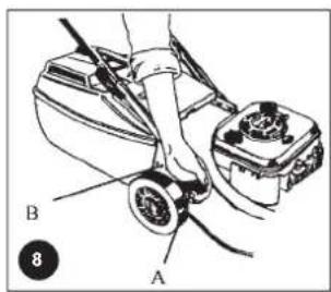

natural_image
Line drawing of a mechanical lever mechanism with a curved arm and pivot point (no text or symbols)WARTUNG

natural_image
Close-up of hands holding a bicycle tire and cable (no visible text or symbols)
natural_image
Close-up of a car's engine compartment with a hand adjusting the wheel (no visible text or symbols)natural_image
Close-up of hands using a tool to adjust or install a mechanical component (no visible text or symbols)natural_image
Close-up of hands adjusting a mechanical component with tools (no visible text or symbols)WARTUNG
natural_image
Mechanical assembly diagram showing a bracket and suspension components (no text or labels visible)
natural_image
Close-up of a hand adjusting a mechanical component with visible gears and springs (no text or symbols)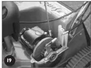
natural_image
Close-up of a mechanical assembly with visible gears and components (no text or symbols)
natural_image
Close-up of a car's wheel assembly with visible gears and components (no text or symbols)
natural_image
Close-up mechanical assembly showing a bracket and spring mechanism (no visible text or symbols)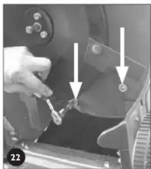
natural_image
Close-up of a hand holding a tool with arrows pointing to a component (no visible text or symbols)WARTUNG
natural_image
Close-up of a hand adjusting a mechanical component with a circular dial and arrow indicator (no visible text or symbols)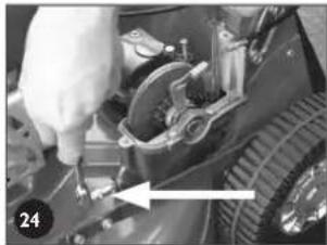
natural_image
Close-up of a hand using a tool to adjust or install a mechanical component, no visible text or symbols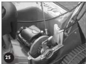
natural_image
Close-up of a car's engine compartment showing internal components and wiring (no visible text or symbols)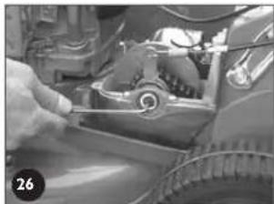
natural_image
Close-up of a mechanical component being adjusted, showing internal parts and a tool (no visible text or symbols)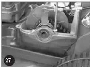
natural_image
Close-up of a mechanical component with internal gears and housing (no visible text or symbols)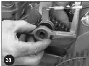
natural_image
Close-up of a hand operating a mechanical component with no visible text or symbols
natural_image
Close-up of a mechanical assembly with a metallic component and a light arrow indicating direction (no visible text or symbols)WARTUNG
natural_image
Close-up of a hand adjusting a tire with a wrench, no visible text or symbols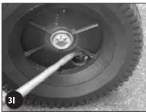
natural_image
Close-up of a tire with a measuring tool inserted, showing tread pattern and central hub (no text or symbols visible)natural_image
Close-up of a mechanical component with a cylindrical assembly and a small bottle, no visible text or symbolsWARTUNG
Vis - 3/16" X 1/2" UNC (2)
Ecrou nyloc - 3/16" UNC (2 inclus)
natural_image
Black-and-white photo of a damaged car trunk with broken body and debris, no visible text or symbols
SPÉCIFICATIONS
natural_image
Technical line drawing of a mechanical device with exploded view and assembled views (no text or symbols)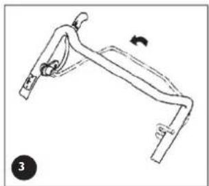
natural_image
Line drawing of a mechanical lever or bracket with a curved arrow indicating motion (no text or symbols)
INSTALLATION (suite)
POUR ENLEVER LES FIXATIONS D'EMBALLAGE DES LEVIERS DE COMMANDE

natural_image
Mechanical linkage diagram showing two arms with black arrows indicating movement or force direction (no text or symbols)UBRIFICATION DU MOTEUR ET CARBURANT

natural_image
Close-up of mechanical components with no visible text or symbolsMODÈLE AUTOTRACTÉ

natural_image
Illustration of hands using a tool to adjust or install a battery pack (no text or symbols visible)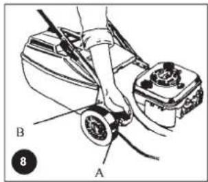
MOTEUR
natural_image
Line drawing of a mechanical lever mechanism with a curved handle and lever arms (no text or symbols)ENTRETIEN

MODÈLE AUTOTRACTÉ

natural_image
Close-up of hands holding a bicycle tire with a black clip (no visible text or symbols)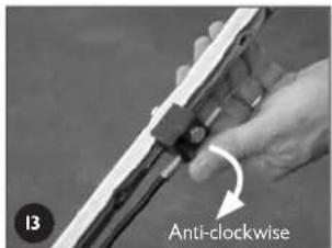
natural_image
Close-up of a car engine component being adjusted with a tool, no visible text or symbolsnatural_image
Close-up of a mechanical assembly with a hand adjusting components (no visible text or symbols)natural_image
Close-up of hands adjusting a mechanical component with a tool (no visible text or symbols)ENTRETIEN (suite)
natural_image
Mechanical assembly diagram showing a lever mechanism with no visible text or symbols
natural_image
Close-up of a hand adjusting a mechanical component with a tire and clamped parts (no visible text or symbols)
natural_image
Close-up of a mechanical device with visible components and wiring (no text or symbols)
natural_image
Close-up of a person working on a car engine component, no visible text or symbols
natural_image
Close-up mechanical assembly showing a bracket and spring mechanism (no visible text or symbols)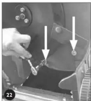
natural_image
Close-up of a hand holding a tool near a mechanical component, with arrows pointing to specific parts (no visible text or symbols)ENTRETIEN (suite)
natural_image
Close-up of a hand adjusting a mechanical component with a circular arrow indicating rotation (no visible text or symbols)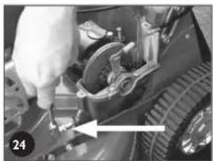
natural_image
Close-up of a hand adjusting a mechanical component with a tool, no visible text or symbols
natural_image
Close-up of a car's engine compartment with visible internal components and no text or symbols
natural_image
Close-up of a car engine component being adjusted, showing internal parts and a hand adjusting the lever (no visible text or symbols)
natural_image
Close-up of a mechanical component with internal gears and housing (no visible text or symbols)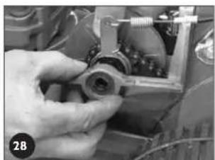
natural_image
Close-up of a hand adjusting a mechanical component with no visible text or symbols
natural_image
Close-up of mechanical components with a highlighted arrow indicating direction (no visible text or symbols)ENTRETIEN (suite)
natural_image
Close-up of hands adjusting a tire with a wrench, no visible text or symbols
natural_image
Close-up of a mechanical wheel with a central knob and a handle, no visible text or symbolsOPTION: DÉMARRAGE ÉLECTRIQUE
natural_image
Close-up of a mechanical component with a threaded fitting and a labeled part (no readable text or symbols)ENTRETIEN (suite)
PROBLEMAS Y POSIBLES SOLUCIONES....54
Genera
natural_image
Black-and-white photo of a damaged vehicle with broken body and debris, no visible text or symbolsDATOS TÉCNICO!
natural_image
Technical line drawing of a mechanical device with exploded view and assembled views (no text or symbols)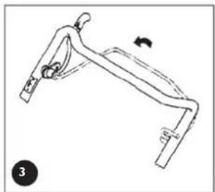
natural_image
Line drawing of a mechanical lever or bracket with a curved handle and a rotation arrow (no text or symbols)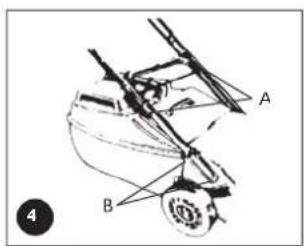
natural_image
Mechanical linkage diagram showing two arms with black arrows indicating movement or force direction (no text or symbols)CÓMO ENGRASAR Y ABASTECER DE COMBUSTIBLE EL MOTOR

natural_image
Close-up of a mechanical clamp or bracket component with visible metal fasteners and a small metallic part (no text or symbols)natural_image
Illustration of hands using a tool to adjust or install a mechanical component (no text or symbols visible)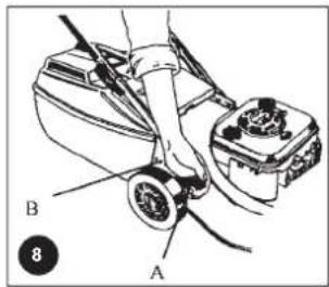

natural_image
Line drawing of a mechanical lever mechanism with a curved handle and lever arms (no text or symbols)MANTENIMIENTO

natural_image
Close-up of hands holding a bicycle tire with a black clip (no visible text or symbols)
natural_image
Close-up of a hand using a tool to adjust or install a vehicle, no visible text or symbolsnatural_image
Close-up of a hand using a tool to adjust or install a mechanical component (no visible text or symbols)natural_image
Close-up of hands adjusting a mechanical component with tools (no visible text or symbols)natural_image
Mechanical assembly diagram showing a rotating component with a directional arrow (no text or symbols)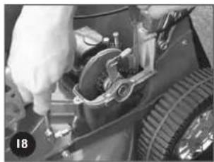
natural_image
Close-up of a hand adjusting a mechanical component with visible gears and tubing (no text or symbols)
natural_image
Close-up of a mechanical device with visible components and wiring (no text or symbols)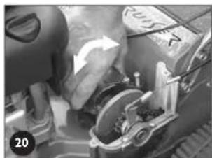
natural_image
Close-up of a person interacting with a mechanical device, no visible text or symbols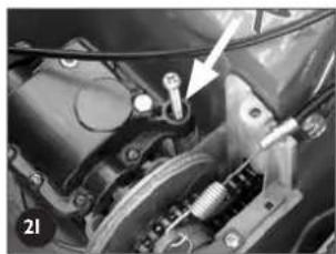
natural_image
Close-up mechanical assembly showing a bracket and spring mechanism (no visible text or symbols)
natural_image
Close-up of a hand using a tool to adjust or install a mechanical component, with arrows pointing to specific parts (no visible text or symbols)natural_image
Close-up of a hand holding a mechanical component with a circular component, no visible text or symbols
natural_image
Close-up of a hand adjusting a mechanical component with a tool, no visible text or symbols
natural_image
Close-up of a car's internal components, including a battery and switch, with no visible text or symbols.
natural_image
Close-up of a hand adjusting a mechanical component with visible gears and tubing (no text or symbols)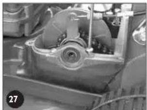
natural_image
Close-up of a mechanical component with internal gears and housing (no visible text or symbols)
natural_image
Close-up of a hand adjusting a mechanical component with visible wiring and components (no text or symbols)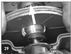
natural_image
Close-up of mechanical assembly with a metallic component and a directional arrow (no visible text or symbols)natural_image
Close-up of hands installing or adjusting a tire on the ground (no visible text or symbols)
natural_image
Close-up of a mechanical tire with a wrench inserted, showing tread pattern and central hub (no text or symbols visible)natural_image
Close-up of a mechanical component with threaded end and attached seal, no visible text or symbolsnatural_image
Black-and-white photo of a damaged vehicle with broken body, boxes, and debris on the ground (no visible text or symbols)SPECIFICATIES
natural_image
Technical line drawing of a mechanical device with exploded view and assembled views (no text or symbols)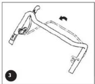
natural_image
Line drawing of a mechanical lever or bracket with a curved arrow indicating motion (no text or symbols)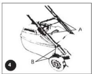
natural_image
Mechanical lever diagram with arrows indicating force or movement (no text or symbols)SMERING VAN DE MOTOR EN BRANDSTOI

natural_image
Close-up of a mechanical clamp or fixture with a transparent rectangular component and metal fittings (no visible text or symbols)DE OPTIE ZELF-RIJDENDE MAAIER

0 (uit), (langzaam), (snel), | (choke)
natural_image
Illustration of hands using a power tool to adjust or install a motor (no text or symbols visible)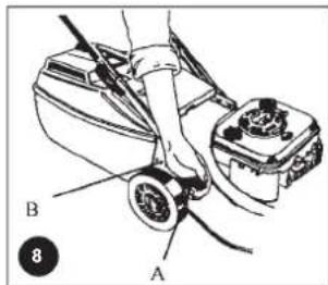
natural_image
Mechanical lever diagram showing a curved arm with a rotating head and base, no text or symbols presentONDERHOUD
DE OPTIE ZELF-RIJDENDE MAAIER

natural_image
Close-up of hands holding a bicycle brake lever and cable (no visible text or symbols)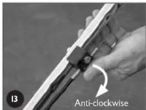
natural_image
Close-up of a car's engine compartment with a hand adjusting the wheel (no visible text or symbols)natural_image
Close-up of a hand using a tool to adjust or install a mechanical component (no visible text or symbols)natural_image
Close-up of hands adjusting a mechanical component with tools (no visible text or symbols)ONDERHOUD (vervolg)
natural_image
Mechanical assembly diagram showing a bracket with mounting holes and a directional arrow (no text or symbols)
natural_image
Close-up of a hand adjusting a mechanical component with visible gears and a tire (no text or symbols)
natural_image
Close-up of a mechanical device with visible components and wiring (no readable text or symbols)
natural_image
Close-up of a car's engine compartment with visible gears and components (no text or symbols)
natural_image
Close-up mechanical assembly showing a car engine and spring-loaded components (no visible text or symbols)
natural_image
Close-up of a hand holding a tool near a mechanical component, with two arrows pointing to specific parts (no visible text or symbols)ONDERHOUD (vervolg)
natural_image
Close-up of a hand holding a mechanical component with a circular component and an arrow indicating rotation (no visible text or symbols)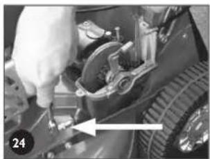
natural_image
Close-up of a hand adjusting a mechanical component with a tool, no visible text or symbols
natural_image
Close-up of a mechanical component with visible parts and a numbered label (25), no readable text or symbols present.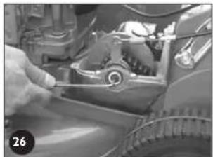
natural_image
Close-up of a car's engine and wheel assembly being adjusted by hand (no visible text or symbols)
natural_image
Close-up of a mechanical component with internal gears and housing (no visible text or symbols)
natural_image
Close-up of hands assembling or adjusting a mechanical component (no visible text or symbols)
natural_image
Close-up of mechanical components with a white arrow indicating direction, no visible text or symbolsONDERHOUD (vervolg)
natural_image
Close-up of a hand adjusting a tire with a tool, no visible text or symbols
natural_image
Close-up of a tire with a dial and a measuring tool inserted, no visible text or symbolsDE POWERSTART OPTIE
natural_image
Close-up of a mechanical component with a threaded fitting and a labeled part (no readable text or symbols)ONDERHOUD (vervolg)
Viti - 3/16" × ½" UNC (2)
Jado Nyloc nut- 3/16 pollici UNC (No. 2)
natural_image
Black-and-white photo of a damaged vehicle with visible internal components and debris on the ground (no text or symbols)
natural_image
Technical line drawing of a mechanical device with exploded view and assembled views (no text or symbols)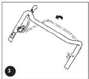
natural_image
Line drawing of a mechanical lever or bracket with a curved arrow indicating motion (no text or symbols)
natural_image
Mechanical linkage diagram showing two arms with arrows indicating movement or force direction (no text or symbols)natural_image
Close-up of mechanical components with no visible text or symbolsnatural_image
Illustration of hands using a tool to adjust or install a mechanical component (no text or symbols visible)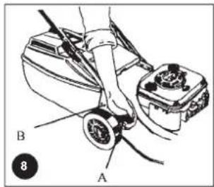

natural_image
Mechanical lever diagram showing a curved arm with a rotating arrow indicating motion (no text or symbols)MANUTENZIONE

natural_image
Close-up of hands holding a bicycle tire and cable (no visible text or symbols)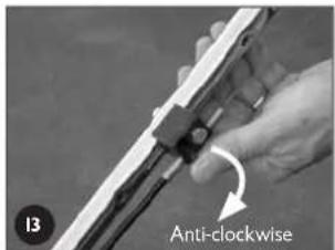

natural_image
Close-up of a car tire being adjusted for a tool, no visible text or symbolsnatural_image
Close-up of hands using a tool to adjust or install a mechanical component (no visible text or symbols)natural_image
Close-up of hands using a tool to adjust or repair a mechanical component (no visible text or symbols)natural_image
Mechanical assembly diagram showing a bracket and mounting bracket with directional arrow (no text or symbols)
natural_image
Close-up of a hand adjusting a mechanical component with visible gears and tools (no text or symbols)
natural_image
Close-up of a mechanical assembly with visible gears and components (no text or symbols)
natural_image
Close-up of a car's engine compartment with visible gears and dashboard (no text or symbols)
natural_image
Close-up mechanical assembly showing a motor and gear mechanism (no visible text or symbols)
natural_image
Close-up of a hand using a tool to adjust or install a mechanical component, with arrows pointing to specific parts (no visible text or symbols)natural_image
Close-up of a hand adjusting a mechanical component with a circular component and a curved arrow (no visible text or symbols)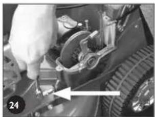
natural_image
Close-up of a hand adjusting a mechanical component with a tool, no visible text or symbols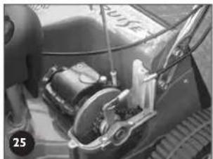
natural_image
Close-up of a motorcycle's front wheel and side arm, no visible text or symbols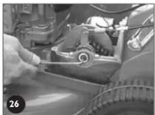
natural_image
Close-up of a hand adjusting a mechanical component with a scroll wheel (no visible text or symbols)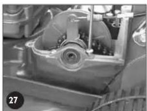
natural_image
Close-up of a mechanical component with visible gears and housing (no text or symbols)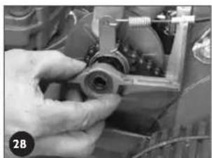
natural_image
Close-up of hands assembling a mechanical component with visible wiring and components (no text or symbols)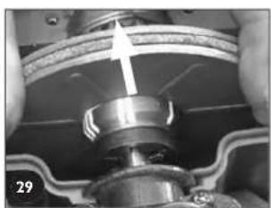
natural_image
Close-up of a mechanical assembly with a metallic component and a light arrow indicating direction (no visible text or symbols)natural_image
Close-up of hands adjusting a tire with a tool, no visible text or symbols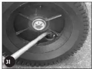
natural_image
Close-up of a tire with a wrench inserted, showing tread pattern and central hub (no text or symbols visible)natural_image
Close-up of a mechanical component with threaded end and attached base, no visible text or symbolsNo. Part No. Description Qty
| 1 | A16135 Base- 20" Push 1 | |
| 1 | A16070 Base- 20" Self propelled | 1 |
| 1 | A16176 Base- 22" Self propelled | 1 |
| 2 | A03510 Height adjustment rack- 20" only | 1 |
| 2 | A16081 Height adjustment rack- 22" only | 1 |
| 3 | A03126 Flap bush | 2 |
| 4 | A03456 Rear flap | 1 |
| 5 | A03325 Flap spring | 1 |
| 6 | A03455 Handle- flap | 1 |
| 7 | A03306 Flap rod | 1 |
| 8 | A290112 Rivet- flap handle | 2 |
| 9 | A04164 Rivet- rack | 2 |
| 10 | A16180 | Chain case- dummy 20" push only | 1 |
| 10 | A16066 | Chain case- 20" & 22" s/prop.only | 1 |
| 11 | A16216 | Infil piece- 20" push only | 1 |
| 12 | A04040 | Rivet- 20" push only | 1 |
| 13 | A04158 | Screw- M5 x 20 | 2 |
| 14 | A04099 | Washer | 2 |
| 15 | A04163 | Nyloc nut- M5 | 2 |
| 16 | A10381 | Axle retainer- 20" CE push | 1 |
| 16 | A03877 | Axle retainer- 20" US push | 1 |
| 16 | A03383 | Axle retainer- 20" & 22" local & CE SP | 1 |
| 16 | A03878 | Axle retainer- 20" & 22" US SP | 1 |
| 17 | A290112 | Rivets- rear axle retainer- 20" push | 4 |
| 18 | A10622 | Rear wheel assembly- 20" push | 2 |
| 19 | A03353 | Wheel bearing | 8 |
| 20 | A373109 | Tension washer | 4 |
| 21 | A03092 | Ratchet plate | 4 |
| 22 | A03414 | Hub cap- chrome | 4 |
| 22 | A16234 | Hub cap- black | 4 |
| 23 | A16014 | Wheel seal | 2 |
| 24 | A10649 | Rear axle assembly- 20" push | 1 |
| 25 | A16220 | Rear axle bush- 20" push | 2 |
| 25 | A16294 | Rear axle bush- 20" & 22" s/prop | 2 |
| 26 | A10284 | Height adjustment lever- 20" only | 1 |
| 26 | A10635 | Height adjustment lever- 22" only | 1 |
| 27 | A03336 | Plate | 1 |
| 28 | A02118 | Rivets- height adj. lever | 2 |
| 29 | A03250 | Handle grip | 1 |
| 30 | A16014 | Wheel seal- 20" push only | 2 |
| 31 | A04164 | Rivet- rack 22" s/prop. only | 1 |
| 32 | A03516K | Axle hook kit | 2 |
| 33 | A10603 | Front axle assy- 20" CE & US Mulch | 1 |
| 33 | A10527 | Front axle assy- 20" Push & S/prop | 1 |
| 33 | A10638 | Front axle assy- 22" S/prop | 1 |
| 33 | A10648 | Front axle assy- 22" CE & US mulch | 1 |
| 34 | A03450 | Front axle bush- 20" push & s/prop | 2 |
| 34 | A03674 | Front axle bush- 22" s/prop | 2 |
| 35 | A16005 | Disc- 20" push & s/prop. only | 1 |
| 36 | A03830 | Blade- standard 20" suits item 35 | 4 |
| 36 | A03930 | Blade- mulch 20" suits item 35 | 4 |
| 37 | A00673K | Blade bolt, nut & washer kit- suits item 35 | 2 |
| 38 | A03999 | Bar blade holder- 20" only | 1 |
| 38 | A16173 | Bar blade holder- 22" only | 1 |
| 39 | A16108 | Blade- 22" | 2 |
| 39 | A16238 | Blade- 22" CE & US only | 2 |
| 40 | A04139K | Blade bolt, nut & washer kit- suits item 38 | 1 |
| 41 | A0555K | Centre bolt kit | 1 |
| 42 | A01486 | Disc boss | 1 |
| 43 | A02051 | Woodruff key | 1 |
| 44 | A10647 | Conbar- standard 20" push & s/prop. | 1 |
| 44 | A10644 | Conbar- standard 22" s/prop. | 1 |
| 45 | A10687 | Conbar complete assy- 20" mulch | 1 |
| 45 | A10710 | Conbar complete assy- 22" mulch | 1 |
| 45 | A10715 | Conbar complete assy.- 20" China | 1 |
| 46 | A10684 | Conbar front assy.- 20" mulch | 1 |
| 46 | A10711 | Conbar front assy.- 22" mulch | 1 |
| 47 | A10686 | Conbar rear assy.- 20" mulch | 1 |
| 47 | A10713 | Conbar rear assy.- 22" mulch | 1 |
| 47 | A10708 | Conbar rear assy.- 20" China | 1 |
| 48 | A04117 | Cuphead bolt | 1 |
| 49 | A02030 | Washer | 1 |
| 50 | A03998 | Handle | 1 |
No. Part No. Description Qty
| 51 | A02223 | Nut | 1 |
| 52 | A10621 | Front wheel assy.- 20" push & s/prop. | 2 |
| 52 | A10622 | Front wheel assy.- 22" s/prop. | 2 |
| 53 | A2501116 | Ratchet plate | 2 |
| 54 | A03995 | Logo | 1 |
| 55 | A04171 | Rivets- logo | 2 |
| 56 | A16076 | Conbar spring- 20" push & s/prop. | 1 |
| 56 | A16219 | Conbar spring- 22" s/prop. | 1 |
| 57 | A02127 | Engine Bolt- B&S | 3 |
| 57 | A02127 | Engine Bolt- Honda GCV 160 | 3 |
| 57 | A04145 | Engine Bolt- Honda GXV 140 | 3 |
| 58 | A02012 | Washer- Flat- Honda GXV 140 | 3 |
| 59 | A02031 | Washer- shakeproof Honda GXV 140 | 3 |
| 60 | A16137 | Nose comb- 20" & 22" CE & US only | 1 |
| 61 | A04111 | Screw- 20" & 22" CE & US only | 2 |
| 62 | A03743 | Label- warning CE only | 1 |
| 63 | A03492 | Label- Noise CE only | 1 |
| 64 | A03934 | Label- warning US only | 1 |
| 65 | A03874 | Label- danger US only | 1 |
| 66 | * | Label- Model | 1 |
| 67 | A04173 | O-Ring | 1 |
| 68 | A16302 | Washport - plastic | 1 |
| 69 | A04038 | Washer- 04.15 x 15 x 18g.flat | 2 |
| 70 | A02175 | Rivet- 73 AS 5-5 | 2 |
SPARE PARTS VIEWS
HANDLE BAR SPARE PART!
No. Part No. Description Qty
| 1 | A03802 | Upper handle bars- 20' | 1 |
| 1 | A03809 | Upper handle bars- 20" prof | 1 |
| 1 | A161/4 | Upper handle bars- 22' | 1 |
| 2 | A16050 | Lower handle bars-20" only | 1 |
| 2 | A16185 | Lower handle bars-20" prof & 22 | 1 |
| 3 | A02849K | Cam lock-incl. item 4, 5, 6 | 2 |
| 4 | A03307 | Draw bolt-cam lock incl. in item : | 2 |
| 5 | A0226C | Roll pin-cam lock incl. in item : | 2 |
| 6 | A0222: | Nyloc nut- 5/16" unc. incl. in item | 4 |
| / | A03518 | Plug spanner- Quantum & Honda | 1 |
| / | A12592 | Plug spanner- Intek | 1 |
| 8 | A03556 | Battery support bo> | 1 |
| 9 | A03559 | Battery | 1 |
| 10 | A03558 | Battery block | 1 |
| 1 | A03610 | Foam block | 1 |
| 12 | A03563 | Label -caution | 1 |
| 1: | A02163 | Screw- 3/16" x 1/2" mush. hea | 2 |
| 14 | A02002 | Speed nut | 2 |
| 15 | A02083 | Setscrew- 5/16" x 3/4" unc.he; | 2 |
| 16 | A02012 | Washer- 5/16" x 1/8" x 18g.lla | 2 |
| 1/ | A11102 | Washer-specia | 2 |
| 18 | A03430 | Lever stop plate | 1 |
| 15 | A03326 | Throttle cable- 20" B&S Ct | 1 |
| 15 | A10641 | Throttle cable- 20" Honda GXV | 1 |
| 15 | A10718 | Throttle cable- 22" B&S Ct | 1 |
| 15 | A10719 | Throttle cable- 22" Honda GXV | 1 |
| 15 | A10721 | Throttle cable- 22" B&S US | 1 |
| 20 | A00950K | Throttle control assembly-briggs | 1 |
| 20 | A10016K | Throttle control assembly-Honda | 1 |
| 21 | A0406C | Rivet-/3 AS 5-2 | 1 |
| 22 | A03565 | Cable clamp | 1 |
| 23 | A0356C | Key start switch | 1 |
| 24 | A07679 | Ignition key: | 2 |
| 25 | A03557 | Key start housing | 1 |
| 26 | A16142 | Wiring loom- 20' | 1 |
| 27 | A02028 | Setscrew- 5/16" x 5/8" -20" onl | 4 |
| 27 | A02083 | Setscrew- 5/16" x 3/4" -20"Prof & 22 | 4 |
| 28 | A04043 | Hanged nut- 5/16" un | 4 |
| 29 | A02081 | Setscrew- 1/4" x 1-3/4" unc | 1 |
| 30 | A02245 | Nyloc nut- 1/4" unc | 1 |
| 31 | A16133 | Clutch cable- 20" | 1 |
| 31 | A16183 | Clutch cable- 22" | 1 |
| 32 | A02521 | Spacer | 1 |
| 3: | A10717 | Clutch lever assembly | 1 |
| 34 | A10523 | Brake lever assembly- 20" pusl | 1 |
| 35 | A10524 | Brake lever assembly- 20 & 22" s/prop | 1 |
| 36 | A03732 | Cable clip-all models | 1 |
| 37 | A03739 | Handle grip | 1 |
| 38 | A03747 | Label-blade brake | 1 |
| 39 | A03622 | Label-drive engagement | 1 |
| 40 | A03756 | Switch plate | 1 |
| 41 | A03933 | Throttle block | 1 |
| 42 | A16004 | Throttle control assembly-US | 1 |
| 43 | A02216 | Washer- 3/16" x 1/2" fla | 1 |
| 44 | A0411 | Screw- 10 x 50 pan hea | 1 |
| 45 | A16233 | Brake cable- 20' | 1 |
| 45 | A16184 | Brake cable- 22' | 1 |
| 46 | A0408: | Screw- 10 x 19 pan hea | 1 |
| 47 | A03733 | Rope stop | 1 |
| 48 | A03732 | Cable clip-powerstart & 20" push | 1 |
| 49 | A02668 | Cable tie-powerstart & s/propellec | 1 |
| 50 | A02668 | Cable tie-self propellec | 1 |
| 51 | A03938 | Label-Powerstart-mulch only | 1 |
| 51 | A03774 | Label-Powerstar | 1 |
SPARE PARTS VIEWS
SELF PROPELLED SPARE PARTS
No. Part No. Description Qty
| 1 | A10624 Wheel assembly- 20" 2 | |
| 1 | A10669 Wheel assembly- 22" 2 | |
| 2 | A03381 Cover Plate- 20" LH | 1 |
| 2 | A03380 Cover Plate- 20" RH | 1 |
| 2 | A16045 Cover Plate- 22" Common | 2 |
| 3 | A03353 Wheel bearing | 4 |
| 4 | A03414 Hub cap | 2 |
| 5 | A3521047 Plug | 2 |
| 6 | A373109 Tension washer | 2 |
| 7 | A03092 Ratchet plate | 2 |
| 8 | A16075 Belt cover | 1 |
| 9 | A16065 Engine pulley | 1 |
| 10 | A16079 Gearbox pulley | 1 |
| 11 | A02051 Woodruff key | 1 |
| 12 | A04075 Grub screw- 1/4" x 3/8" unc | 2 |
| 13 | A04073 Roll pin- gearbox pulley 5 x 40 | 1 |
| 14 | A04167 Setscrew- M5 x 16 hex. | 2 |
| 15 | A04099 Washer- 3/16" x 3/4" x 16g | 2 |
| 16 | A10639 Rear axle assembly- complete 20" | 1 |
| 16 | A10637 Rear axle assembly- complete 22" | 1 |
| 17 | A16294 Axle bush | 2 |
| 18 | A10284 Height adjustment lever- 20" | 1 |
| 18 | A10635 Height adjustment lever- 22" | 1 |
| 19 | A03250 Handle grip | 1 |
| 20 | A03336 Packing plate | 1 |
| 21 | A02118 Rivets- 1/4" x 3/4" | 2 |
| 22 | A02090 Circlip | 4 |
| 23 | A03373 Pawl retainer | 4 |
| 24 | A03372 Pawl | 2 |
| 25 | A03370 Pinion- LH | 1 |
| 26 | A03361 Bearing | 2 |
| 27 | A03371 Pinion- RH | 1 |
| 28 | A16131 Drive frame | 1 |
| 29 | A10640 Gearbox assembly | 1 |
| 30 | A16063 Frame cover | 1 |
| 31 | A16061 Cap- spring | 1 |
| 32 | A16064 Spring- gearbox | 1 |
| 33 | A10636 Clutch plate assembly- incl. item 34 | 1 |
| 34 | A03390 Clutch lining | 1 |
| 35 | A16322 Spring- clutch plates | 1 |
| 36 | A10170 Clutch plate assembly- drive | 1 |
| 37 | A16056 Thrust washer | 1 |
| 38 | A16323 Spring- cam lever | 1 |
| 39 | A16057 Cam lever | 1 |
| 40 | A16060 Bearing retainer and cam | 1 |
| 41 | A16139 Thrust cap | 1 |
| 42 | A04165 Screw- M6 x 12 csk. Cap screw | 1 |
| 43 | A16062 Bearing cap | 1 |
| 44 | A02111 Nyloc nut- M6 | 2 |
| 45 | A04162 Screw- M6 x 60 | 1 |
| 46 | A04161 Screw- M6 x 70 | 1 |
| 47 | A04091 Screw- M5 x 16 | 3 |
| 48 | A04157 Roll pin- gearbox shaft | 1 |
| 49 | A04163 Nyloc nut- M5 | 9 |
| 50 | A04160 Screw- M5 x 40 | 3 |
| 51 | A16337 Label- Caution Drive Belt Tension | 1 |
| 52 | A16066 Chain case | 1 |
| 53 | A16069 Wedge | 1 |
| 54 | A16068 Chain tensioner | 1 |
| 55 | A16071 Axle supports | 2 |
| 56 | A16072 Sprocket- 12 tooth (suits 1/8" x 3/4" roll pin) | 1 |
| 56 | A16360 Sprocket- 12 tooth (suits 5/32" x 3/4" roll pin) | 1 |
| 57 | A03394 Felt seal | 1 |
| 58 | A02069 Roll pin- drive shaft (suits 1/8" x 3/4" roll pin) | 1 |
| 58 | A04174 Roll pin- drive shaft (suits 5/32" x 3/4" roll pin) | 1 |
| 59 | A16058 Drive shaft- 20" (suits 1/8" x 3/4" roll pin) | 1 |
| 59 | A16179 Drive shaft- 22" (suits 1/8" x 3/4" roll pin) | 1 |
| 59 | A16361 Drive shaft- 22" (suits 5/32" x 3/4" roll pin) | 1 |
| 60 | A03391 Mount bracket | 1 |
| 61 | A03383 Rear axle retainer- CE | 1 |
| 61 | A03878 Rear axle retainer- US | 1 |
| 62 | A03393 Drive shaft shield- CE | 1 |
| 62 | A03879 Drive shaft shield- US | 1 |
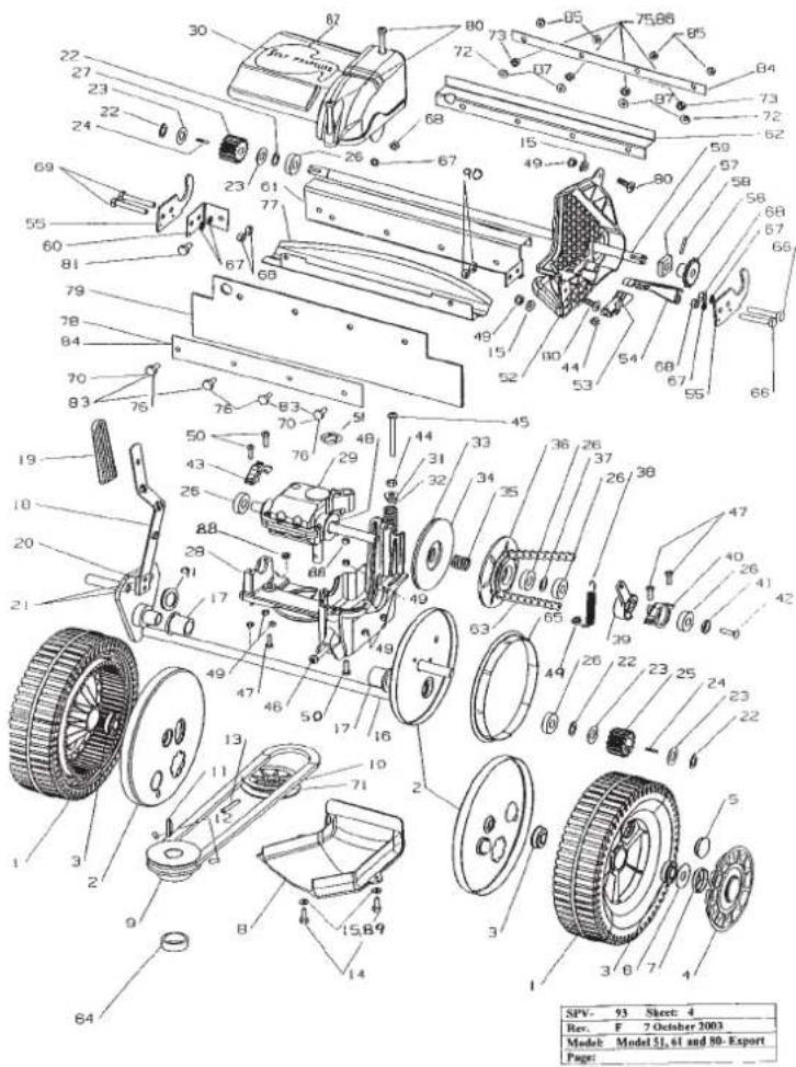
No. Part No. Description Qty
| 63 | A16078 | Chain- 3/8" x 58 pitch ASA incl. con link | 1 |
| 64 | A16182 | Spacer- engine pulley 20" only | 1 |
| 65 | A03382 | Seal- rear wheel 20" only | 2 |
| 66 | A02081 | Setscrew- 1/4" x 1-3/4" unc. hex. | 2 |
| 67 | A02027 | Washer- 1/4" spring | 5 |
| 68 | A02001 | Nut- 1/4" hex. | 5 |
| 69 | A02146 | Setscrew- 1/4" x 3/4" unc. hex. | 2 |
| 70 | A02078 | Setscrew- 1/4" x 1/2" unc. hex. CE only | 2 |
| 71 | A16077 | Belt- Dayco SPZX-612 20" only | 1 |
| 71 | A16217 | Belt- Dayco SPZX-670 22" only | 1 |
| 72 | A02027 | Washer- 1/4" spring CE only | 2 |
| 73 | A02001 | Nut- 1/4" unc. hex. CE only | 2 |
| 75 | A02235 | Nyloc nut- 1/4" unc- 20" US only | 4 |
| 76 | A02214 | Setscrew- 1/4" x 5/8" unc. hex. 20" US | 4 |
| 77 | A03604 | Extension- CE mowers only | 1 |
| 78 | A03881 | Backing plate- 20" US only | 1 |
| 79 | A03883 | Rubber flap- 20" only | 1 |
| 79 | A16235 | Rubber flap- 22" only | 1 |
| 80 | A04158 | Screw- M5 x 20 | 4 |
| 81 | A02078 | Setscrew- 1/4" x 1/2" unc. hex. | 1 |
| 82 | A16239 | Label- Self propelled cover | 1 |
| 83 | A02169 | Setscrew- 1/4" x 1" unc. 22" US only | 4 |
| 84 | A16284 | Backing plate- 22" US only | 2 |
| 85 | A02235 | Nyloc nut- 1/4" unc. 22" US only | 4 |
| 86 | A02001 | Nut- 1/4" unc. hex. 22" US only | 4 |
| 87 | A02027 | Washer- 1/4" spring 22" US only | 4 |
| 88 | A04169 | Nut- M5 hex. | 2 |
| 89 | A02234 | Washer- 3/16" shakeproof | 2 |
| 90 | A02235 | Nyloc nut- 1/4" hex. | 2 |
| 91 | A04013 | Washer- 3/4" x 1- 1/2" flat | 1 |
SPARE PARTS VIEW!
ANCILLARY SPARE PARTS
No. Part No. Description Qty
| 1 | J1014 | Grass catcher assembly | 1 |
| 2 | A0344/ | Handle | 1 |
| 3 | A0324 | Mest | 1 |
| 4 | A02216 | Washer- 3/16" x 1/2" fla | 2 |
| 5 | |||
| 6 | A021/5 | Rivet- /3 AS 5- | 4 |
| 7 | A02163 | Screw- 3/16" x 1/2' | 2 |
| 8 | A02193 | Nyloc Nut- 3/16" un | 2 |
| 9 | A04083 | Washer | 4 |
| 10 | A10689 | Mulch Plug assembly 20' | 1 |
| 10 | A10/14 | Mulch Plug assembly 22' | 1 |
| 1 | A03901 | Deflector | 1 |
| 1 | A03914 | Support Bracket | 1 |
| 1 | A2901195 | Rivet- /3 AS 6- | 2 |
| 1 | A021/5 | Rivet- /3 AS 5- | 2 |
| 1 | A02192 | Washer- 5/32" x 7/16" fla | 2 |
| 16 | A03894 | Label - Mulch Plug | 1 |
| 1 | A03928 | Label - Vari-tilt | 1 |
| 18 | J10605 | Side chute assembly c/w carton | 1 |
| 15 | A03/43 | Label - Chute | 1 |
| 20 | A038/5 | Label - Catcher - US | 1 |
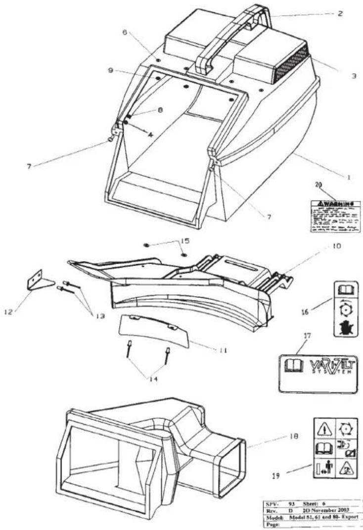
SPARE PARTS VIEWS
HANDLEBARS AV
No. Part No. Description Qty
| 1 | A16875 20" Upper Handlebar- Anti Vibration 1 |
| 1 | A16872 22" Upper Handlebar- Anti Vibration 1 |
| 2 | A16869 18-22" Middle Handlebar Anti Vibration 1 |
| 3 | A16050 Lower Handlebars-20" only 1 |
| 3 | A16185 Lower Handlebars-20" Prof & 22" 1 |
| 4 | A16873 20" & 22" Brace- Anti Vibration 1 |
| 5 | A16877 Anti Vibration Mounts 4 |
| 6 | A04188 M8 Nyloc Nut 8 |
| 7 | A04206 M8 Washer 8 |
| 8 | A04221 M6x40mm Button Head Screw Cap 2 |
| 9 | A04202 M6 Nyloc Nut 2 |
| 10 | A04205 M6 Washer 2 |
| 11 | A16878 Anti Vibration End Plugs 2 |
| 12 | A03126 Bush 2 |
| 13 | A02849K Cam lock- incl. item 14,15,16 2 |
| 14 | A03307 Draw bolt- cam lock Incl. in item 13 2 |
| 15 | A02260 Roll pin- cam lock Incl. In item 13 2 |
| 16 | A02223 Nyloc nut- 5/16" unc. Incl. in item 13 2 |
| 17 | A03430 Lever stop plate 1 |
| 18 | A10702 Throttle cable 20"- 1235mm (Outer Cable Length)(Suits IS000) 1 |
| 18 | A10765 Throttle cable 22"- 1340mm (Outer Cable Length)(Suits IS000) 1 |
| 19 | A10720K Throttle control assembly/Choke 1 |
| 20 | A02028 Setscrew- 5/16" x 5/8"-20" only 4 |
| 20 | A02083 Setscrew- 5/16" x 3/4"-20" Prof & 22" 4 |
| 21 | A04045 Flanged nut- 5/16" unc 4 |
| 22 | A10523 Brake lever assembly- 20" push 1 |
| 23 | A03732 Cable clip- all models 1 |
| 24 | A03747 Label- blade brake 1 |
| 25 | A16233 Brake cable- 20" 1 |
| 25 | A16184 Brake cable- 22" 1 |
| 26 | A04083 Screw- 10 x 19 pan head 1 |
| 27 | A02668 Cable tie- self propelled 1 |
| 28 | A16324 Soft grips 2 |
| 29 | A02081 Setscrew- 1/4" x 1-3/4" unc 1 |
| 30 | A02235 Nyloc nut- 1/4" unc 1 |
| 31 | A16177 Clutch cable- 20" 1 |
| 31 | A16378 Clutch cable- 22" 1 |
| 32 | A09146 Spacer 2 |
| 33 | A10717 Clutch lever assembly 1 |
| 34 | A10524 Brake lever assembly- 20 & 22" s/prop. 1 |
| 35 | A03739 Handle grip 1 |
| 36 | A16391 Spring- clutch cable 1 |
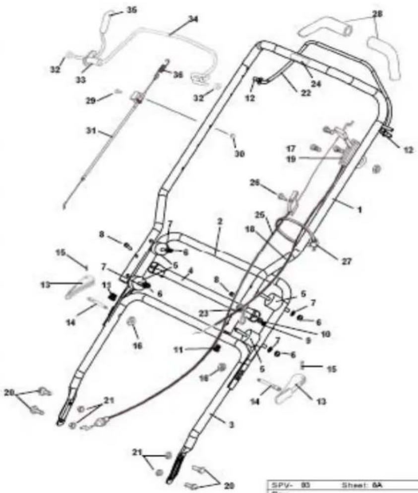
| SPV- | 80 | Sheet: 6A |
| Rev. | ||
| Model: | 51, 61 & 80 CE Hardelsbare AV | |
| Page: | ||
These machines are covered by one or more of the following Registered
Designs and or Patents;
Registered Designs: Australian. 131504, 134850, New Zealand. 40232
Patents: Australian, 713852, 729036, 745750, New Zealand, 330
US. 6085508, UK. GR23251:, Australian. 2007200377
Australian. & PCT Patent application. 2RO998
Registered Design applications: Australia. 1923/200
GB For your record
| Dealer | P | r | o | d | u |
| • Name: | • Model number: | ||||
| • Address: | • Serial number: | ||||
| • Phone No: | • Date of purchase: | ||||
MTD Products Australia
PO Box 376
Dandenong Victoria 3175
Australia