Rancher 27155 - Lawn mower Rover - Free user manual and instructions
Find the device manual for free Rancher 27155 Rover in PDF.

| Product Type | Lawn Mower |
| Brand | Rover |
| Model | Rancher 27155 |
| Power Source | Gasoline |
| Engine Type | Briggs & Stratton 6.75 ft-lb gross torque |
| Cutting Width | 21 inches |
| Cutting Height Range | 1.25 - 4.0 inches (6 positions) |
| Grass Bag Capacity | 2 bushels |
| Weight | 80 lbs (36 kg) |
| Dimensions (L x W x H) | 60 x 22 x 40 inches |
| Wheel Size (Front / Rear) | 8 inches / 10 inches |
| Self-Propelled | Yes, rear-wheel drive |
| Starting System | Recoil start |
| Deck Material | Steel |
| Mulching Capability | Yes (mulching plug included) |
| Side Discharge | Yes |
| Warranty | 2 years limited |
| Recommended Oil | SAE 30 (above 40°F) or SAE 10W-30 (all temps) |
| Spark Plug | Champion RJ19LM or equivalent |
| Air Filter | Foam element (washable) |
Frequently Asked Questions - Rancher 27155 Rover
User questions about Rancher 27155 Rover
0 question about this device. Answer the ones you know or ask your own.
Ask a new question about this device
Download the instructions for your Lawn mower in PDF format for free! Find your manual Rancher 27155 - Rover and take your electronic device back in hand. On this page are published all the documents necessary for the use of your device. Rancher 27155 by Rover.
USER MANUAL Rancher 27155 Rover
natural_image
Line drawing of a grass tractor with front wheel, side rear wheel, and driver compartment (no text or symbols)SAFETY INSTRUCTIONS

This product is manufactured to comply with Australian Safety Standards. If non-genuine replacement parts; including blades; are fitted to this product it may no longer meet that Australian Safety Standard and Rover Mowers Warranty. The fitting of non-genuine replacement parts could result in a serious injury, and, or machine malfunctioning which may result in litigation against the person or persons responsible for the alterations.
* Know your controls. Read the owner's manual carefully. Learn how to stop the engine quickly in any emergency.
* Do not allow children or people unfamiliar with these instructions to use the mower. Do not carry passengers.
* Make sure the lawn is clear of sticks, stones, bones, wire and debris. They could be thrown by the blade.
* Do not mow whilst people, especially children, or pets are in the mowing area.
* Never mow across the face of the slope, unless the mower is designed for this purpose.
* Exercise extreme caution when on slopes. Reduce speed on slopes and in sharp turns to prevent overturning or loss of control.
Do not stop or start suddenly when going uphill or downhill.
* Stay alert for holes in the terrain and other hidden hazards.
Use care when pulling loads or using heavy equipment
(a) use only approved drawbar hitch points
(b) limit loads to those you can safely control
(c) do not turn sharply
(d) use care when backing up, and
(e) use counterweight(s) or wheel weights when suggested in the owner's manual.
* Watch out for traffic when crossing or operating the mower near roadways.
* Stop the blades rotating before crossing surfaces other than grass.
* When using any attachments, never direct discharge of material toward bystanders nor allow anyone near the machine while it is in operation.
* Before leaving the operator's position -
(a) disengage all clutches and secure cutting units
(b) change into neutral and set the parking brake, and
(c) stop the engine and remove the key.
* Stop the engine and disengage drive to attachments -
(a) before refuelling
(b) before making height adjustment unless adjustment can be made from the operator's position
(c) before clearing blockages
(d) before checking, cleaning or working on the mower
(e) after striking a foreign object (inspect the mower for damage and make repairs before restarting and operating the equipment) and
(f) if machine starts to vibrate abnormally (check immediately).
* Disengage drive to attachments when transporting or not in use.
* A mower operator should be in good mental health and not under the influence of any drug or alcohol which might impair vision, co-ordination or judgement.
* Never mow while barefoot or wearing open sandals, or thongs. Wear long trousers and heavy shoes.
* It is advisable to wear suitable eye protection when operating a mower.
* Mow only in good daylight.
* Before using, always visually inspect to see that blades, blade bolts and cutter assembly are not worn or damaged.
* Replace worn or damaged blades and bolts in sets to preserve balance.
DAMAGED BLADES AND WORN BOLTS ARE MAJOR HAZARDS
* Check all nuts, bolts and screws often, always be sure the mower is in a safe operating condition.
* Keep safety devices (guards and switches) in place and in working order.
* Never use the mower unless the grass catcher, or guards provided by the manufacturer, are in position.
* Ensure any spare parts used comply with the original manufacturer's recommendations and specifications.
* Replace worn or faulty silencer.
* Keep engine free of grass, leaves or excessive grease. These can be a fire hazard.
* Refuel outdoors only. Do not smoke while fuelling engine. Never remove the cap of the fuel tank or add petrol while the engine is running or the engine is hot. Remove fuel cap slowly to relieve any tank pressure. If petrol is spilled, do not attempt to start the engine but move machine away from the area of the spill and avoid creating any source of ignition until petrol vapours have dissipated.
* Check for fuel leaks while refuelling or using the mower. If a fuel leak is found, do not start or run the engine until the fuel leak is fixed and spilled fuel is wiped away.
* Do not operate the engine in a confined space where exhaust fumes (carbon monoxide) can collect.
* Always mount the mower on the opposite side to the discharge chute.
* Start the engine carefully with the cutting means disengaged.
* Do not over-speed the engine or alter governor settings. Excessive speed is dangerous and shortens mower life.
* Stop the engine whenever you leave the mower, even for a moment.
* Store the mower in a well-ventilated room away from naked flames such as may be found in hot water heaters.
* Do not lend or sell the mower without the Owner's Manual.

WARNING
If fitted with accessories, including any authorised Rover accessories such as Grass Catcher, this mower may not comply with AS 3792.1
Congratulations you have purchased a quality Australian made product made by a totally Australian owned Company (Rover Mowers Limited).
This manual covers the operation and maintenance of the Rancher and Raider Selector Drive ride-on mower. Please read and understand this owners manual, and the accompanying engine manufacturers manual. If any point is unclear, contact Rover Mowers Limited or any authorised Rover Mower service dealer.
To emphasise special information, the words WARNING and CAUTION are used.

WARNING
The safety of the user and others involved. Personal injury may result should this information be disregarded.
CONTENTS Page
Safety instructions.... i
Preface ii
- Specifications.... 1
1.1 Engine 1
1.2 Transmission 1
1.3 Cutterheads 1
1.4 Tyres 1
1.5 Loose parts kit 1
- Setting up 1
2.1 Installing the steering wheel 1
2.2 Installing the stoneguard 1
2.3 Installing the battery 1
- Controls 2
3.1 Throttle control 2
3.2 Ignition switch 2
3.3 Brake clutch pedal 2
3.4 Parking brake 2
3.5 Speed selector 2
3.6 Cut height and engagement lever 2
3.7 Safety interlock system 2
- Before starting 3
4.1 Engine lubrication 3
4.2 Fuel 3
4.3 Seat adjustment 3
- Operation 3
5.1 To start the engine 3
5.2 To drive or mow 3
5.3 To stop the engine 3
5.4 Engaging clutches 3
5.5 Cutterhead 3

CAUTION
Follow these instructions to avoid mower damage and possible loss of warranty
- Maintenance 4
6.1 Oil change 4
6.2 Lubrication points 4
6.3 Cutterhead removal 4
6.4 Wheel removal 4
6.5 Rear Hub removal 4
6.6 Rear hub fitment 4
6.7 Transaxle removal 4
6.8 Transaxle fitment 5
6.9 Transaxle brake adjustment 5
6.10 Clutch rod adjustment 5
6.11 Cutterhead leveling 5
6.12 Cutterhead tilt 5
6.13 Cutterhead low cut setting 5
6.14 Cutterhead disengagement 6
6.15 Cutterhead brake adjustment 6
6.16 Cutterhead brake pad replacement 6
6.17 Steering gear adjustment 6
6.18 Safety interlock adjustment 6
6.19 Front axle beam 7
6.20 Maintenance Chart 7
6.21 Electrical schematic-Rancher model 27169, Raider model 4056 & Raider model 4083 ... 8
6.22 Electrical schematic-Rancher model 27168, & Rancher model 27155 9
- Trouble shooting.... 10
ILLUSTRATIONS
Figure 3.1 Dash panel and foot pedal 2
Figure 3.2 Foot and hand controls 2
Figure 6.3 Cutterhead support plates 4
Figure 6.4 Disc pad adjustment 5
Figure 6.5 Jockey arm swivel block 5
Figure 6.6 Cutterhead conbar 5
Figure 6.7 Cutterhead lift rod 5
Figure 6.8 Engagement rollers 6
Figure 6.9 Steering pivot block 6
Figure 6.10 Brake Clutch Safety Switch 6
Figure 6.11 Cutterhead Safety Switch 6
| 1.1 Engine Ranchers | Raiders | ||||
| Model No: 27169 27168 27155 | 4056 4083 | ||||
| Make B&S B&S B&S B&S | Tecumseh | ||||
| Engine No: 21A977 285H77 31 | H777 217977 OHV 135 | ||||
| Power - Hp 13 | 15.5 | 18 | 11.5 | 13.5 | |
| Fuel cap. - Litres | 6.5 Litres | ||||
| Oil cap. no filter | 1.4 Litres | 0.94 litres | |||
| Oil cap. c/w filter | 1.7 c/w filter | 1.15 litres | |||
| Oil grade | Refer to engine owner's manual | ||||
| Spark plug | RC 12YC | RN 4C | |||
| Spark plug gap | 0.7mm to 0.8mm | ||||
1.2 Transmission
Combined gearbox and differential in a sealed unit. Featuring 5 forward speeds, neutral and reverse.
Ground speeds with engine at full speed (max RPM)
| Rancher | Raider | Rancher | Raider | ||
| 1^st | 2.4 | 2.1 | 4^th | 7.5 | 6.7 |
| 2^nd | 3.7 | 3.3 | 5^th | 8.7 | 7.7 |
| 3^rd | 5.6 | 5 | Rev. | 2.4 | 2.1 |
1.3 Cutterhead
760mm wide cut pressed steel cutterhead - Rancher & Raider 965mm wide cut pressed steel cutterhead - Rancher only

CAUTION
Never change gears unless machine is at rest and clutch brake pedal depressed.
1.4 Tyres
Front- 13 x 5.00 x 6 tubed 140 KPa pressure - Rancher & Raider Rear- 18 x 8.50 x 8 tubed 70 KPa pressure - Rancher only Rear- 16 x 8.50 x 8 tubed 70 KPa pressure - Raider only
1.5 Loose parts kit
| Description | Quantity |
| Steering wheel | 1 |
| Roll pin | 1 |
| Stoneguard | 1 |
| Stoneguard spring | 1 |
| “E” clip | 1 |
| Ignition keys | 2 |
| Plug spanner | 1 |
| Engine Owners Manual | 1 |
| Rover Owners Manual | 1 |
- SETTING UP
2.1 Installing the steering wheel
- Slide the steering wheel over the steering shaft and align the roll pin holes.
- Insert a drift punch partially through the holes to maintain alignment and insert the roll pin.
- Drive the roll pin in until flush with the outside of the steering wheel.
2.2 Installing the stoneguard
- Slip the stoneguard spring on to the long leg of the stoneguard pivot rod.
- Twist the stoneguard spring and insert the long leg of the stoneguard pivot rod into the forward pivot bracket of the cutterhead.
- Slide the stoneguard back to insert the short leg of the stoneguard pivot rod into the rear pivot bracket of the cutterhead.
- Release the stoneguard spring.
- Fit the "E" clip to the groove on the short leg of the stoneguard pivot rod.
2.3 Installing the battery
- Remove the battery from the mower.
- Add 33% strength battery electrolyte to each cell of the battery until the plates are covered.

CAUTION
Do not overfill the battery. Acid will overflow onto other parts of the machine and severe corrosion will result.
- Charge the battery at 4amps/hour for a minimum of 6 hours.
- After charging check that the plates are covered by the electrolyte, if not, add electrolyte to the correct level.
- Refit the battery to the mower.
- Connect the battery leads to the battery. Red to the positive (+) terminal, black to the negative (-) terminal.
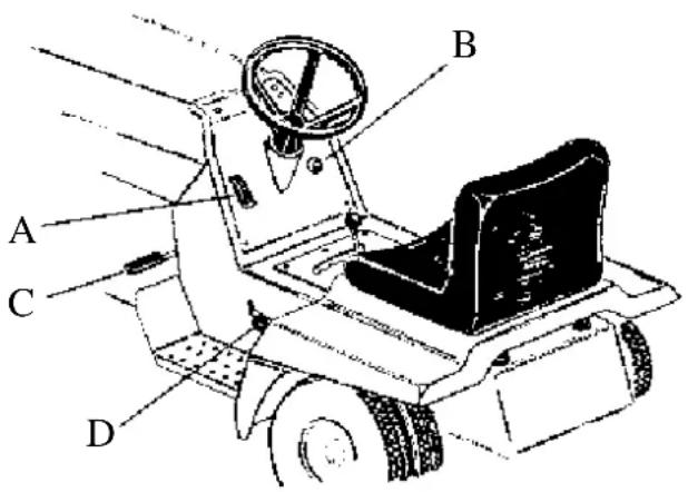
3.1 Throttle control (A)
Mounted on the left hand side of the dash panel. Marked for Slow, Fast and Choke positions. Figure 3.1.
3.2 Ignition switch (B)
Mounted on the right hand side of the dash panel. Marked for Off, On and Start positions. Figure 3.1.
3.3 Brake Clutch pedal (C)
Foot operated pedal mounted on the left hand machine. Depressing the pedal disengages the drive and engages the disc brake. Figure 3.1.
3.4 Parking brake (D)
Hand operated knob mounted on the left hand side of the machine. Parking brake is locked on when the clutch brake pedal is depressed and the parking brake knob is engaged by lifting upward. Depressing the clutch brake pedal releases the parking brake. Figure 3.1.
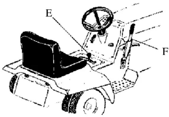
3.5 Speed selection (E)
Hand operated lever mounted centrally on the chassis beneath the steering wheel. Marked for 5 forward speeds, neutral and reverse. Figure 3.2.
3.6 Cut height and engagement lever (F)
Combined lever located on the right hand side of machine. Cutter disengaged and the brake applied when the sicleer is pulled right back and engaged when moved forward. Marked with 8 positions from 15 to 65mm. Figure 3.2.
text_image
A B C DFigure 3.1 Dash panel and foot pedal
text_image
E FFigure 3.2 Foot and hand controls
3.7 Safety Interlock System
The safety interlock system has been designed for the operators safety. It gives the Rover Rancher the following characteristics and should NEVER be tampered with.
The engine will not start unless;
- The cut height engagement lever is in the disengaged position
- The clutch brake pedal is depressed.
The engine will stop if the operator leaves the seat without first locking on the parking brake and disengaging the cutterhead.

WARNING
DO NOT operate the mower if the safety system becomes defective. Contact the nearest Rover authorised service dealer or agent to rectify the problem.
4.1 Engine lubrication
The engine oil level must be checked before attempting to start the engine. Refer to the engine manufacturer's instructions.
- Position the mower on a level surface. Open the bonnet and clean around the dip stick.
- Remove the dip stick from the oil filler tube.
- Using a funnel slowly add oil in accordance with the engine manufacturer's instructions.
- Check the oil level by screwing in the dip stick and removing again. When the oil level is correct replace the dip stick.

CAUTION
Avoid premature engine failure by using funnel and cleaning away any possible contaminants.
4.2 Fuel
- Position the mower on a level surface in a well ventilated ter's area. Open the bonnet and clean around the fuel tank cap.
- Remove the fuel tank cap.
- Using a clean funnel fill the fuel tank with unleaded petrol.
- Replace the fuel tank cap.
- Wipe up any spilt petrol.
- Close and secure the bonnet.
4.3 Seat adjustment
- Tip the seat forward and loosen the four seat retaining bolts.
-
Slide the seat forward or back to suit the operator.
a clean Tighten the four seat retaining bolts and lower the seat. -
OPERATION
5.1 To start the engine
- Depress the clutch brake pedal.
- Move the drive selector to neutral.
- Disengage the cutter drive.
- Move the throttle lever to the choke position.
- Turn the ignition key to the start position and release when the engine starts.
- Move the throttle lever to the slow position.
5.2 To drive or mow
- Depress the clutch brake pedal.
- Move the throttle to the fast position.
- Engage the cut height engagement lever and select the height of cut.
- Select the desired speed to suit conditions.
- Slowly release the clutch brake pedal.
5.3 To stop the engine
- Depress the clutch brake pedal.
- Apply the parking brake.
- Disengage the cut height engagement lever.
- Move the speed selector to neutral.
- Move throttle lever to the fast position.
- Turn the ignition key to the off position, and remove the ignition key before leaving the mower. Place the key in a secure place not available to children or unauthorised persons.
5.4 Engaging clutches
When engaging the cutter drive lever or releasing the clutch brake pedal, always operate slowly. Do not use a jerking motion. Moving these controls too fast could possibly overload and stall the engine.

CAUTION
To avoid loss of control always come to complete stop before selecting speeds and slow down before turning.
5.5 Cutterhead
- Always remove the spark plug lead and disengage the cutter drive before working on the cutterhead.
- Before using the mower always inspect the cutterhead to see that the cutting disc, blades and blades fasteners are not worn, loose or damaged.
- Always check the cutterhead after striking a solid object. Never operate the mower when unusual vibration occurs.
- Always replace blades in sets to preserve balance.
- Remove any build-up of grass or clogging with-in the cutterhead.
6.1 Oil change
Refer to the engine manufacturer's instructions.
- Position the mower on a level surface in a well ventilated area.
- Start and run the engine for 5 minutes to warm up the engine oil.
- Place a suitable container under the oil outlet on the right hand side of the mower.
- Using a suitable spanner remove the drain loosen the drain cock and allow oil to drain completely.
- Replace the drain plug or tighten drain cock.
- Fill the engine crankcase with oil, refer to section 4.1 Engine lubrication.
6.2 Lubrication points
Using general purpose grease.
- Grease nipples on the steering shaft pivot block.
- Cutterhead support plates.
- Front axle beams.
- Grease nipples on front stub axles.
Using 10w-30 or SAE30 oil
- Jockey arm pivot.
- Throttle control cable.
- Clutch brake pedal pivot.
- Tie rod ends.
| CAUTION | |
| All bearings are sealed for life and do lubrication. |
6.3 Cutterhead removal
- Remove the spark plug lead from the spark plug and move the cutterhead to the low cut position.
- Remove the cutterhead tension springs. Use a piece of wire hooked through the loop in the tension springs to assist in their removal.
- Remove the engine pulley belt guard from around the engine pulley by removing the two 5/16" unc. retaining bolts, nuts and washers.
- Remove the cutterhead drive belt by running it off the engine pulley.
- Disconnect the cutterhead lift rod by removing spring clip where it is connected to the cutterhead.
- Remove the two front cutterhead support bolts (A) and lower the front of the cutterhead to the ground. Fig 6.3
- Remove the two rear cutterhead support bolts, (B), and lower the rear of the cutterhead to the ground. Fig 6.3
- Slide the cutterhead out from under the ride-on.

text_image
A Front Supports B Rear SupportsFigure 6.3 Cutterhead Support Plates
6.4 Wheel removal
Front wheels
| WARNING |
| Always deflate the tyre before removing rim nuts from the front wheel rims. |
plug Chock the rear wheels and remove the front wheel axle nut, using a 15/16"AF socket spanner.
- Raise the front of the mower.
- Slide the wheel off the axle.
- Replace in reverse order and tighten the axle nut.
Rear wheels
- Chock the front wheels and raise the rear of the mower.
- Remove the four wheel rim nuts using a 9/16" AF socket spanner.
- Slide the rear wheel off the wheel hub.
- Replace the rear wheel to the wheel hub and retain using the four wheel nuts.
- Tighten the wheel nuts and lower the mower to the ground.
6.5 Rear hub removal
- Remove the rear wheel per section 6.4 (Rear wheels)
- Remove the circlip from the end of the axle shaft.
not require remove the two grub screws from the hub. - Slide the hub off the shaft with the aid of a puller. Never use a hammer.
6.6 Rear hub fitment
- Coat the axle shaft with 'Never-Seize' compound.
- Place key in axle keyway and slide hub into position, and fit circlip.
- Apply 'Loctite 243' to the grub screws and screw tightly into the hub.
- Replace the wheel and four wheel retaining nuts.
6.7 Transaxle removal
- Place the ride-on, on a level dry surface, appl parking brake, move the gear lever to the neutral position and remove the ignition key.
- Remove the two cutterhead springs.
- Remove the brake rod tension springs, starting a small one first.
- Remove the four retaining bolts between the chassis and transaxle unit (1/2" AF) and the two self tappers between transaxle unit and cross bracket (1/2 A/F).
- Remove the bolt between the gear lever selector bracket and transaxle spigot and lift out gear lever.
- Remove the transaxle drive belt from around the transaxle pulley.
- Gently jack up the rear of the ride-on off the transaxle unit taking care not to damage the transaxle pulley.
6.8 Transaxle fitment
- With rear of the ride-on raised slide the transaxle unit under the rear of the chassis.
- Lower the ride-on aligning the chassis mounting holes with the transaxle mounting holes. Fit the four retaining bolts and nuts between transaxle unit and chassis but do not tighten.
- Loosen the two bolts between the chassis sides and transaxle cross bracket.
- Align the transaxle cross bracket with the transaxle and apply loctite 243 to the two self tapper screws and tighten cross bracket to transaxle.
- Position the transaxle to give a 5mm air gap through back of middle slot and transaxle. Tighten the four retaining bolts between the chassis sides and cross bracket.
- Fit the gear lever bracket over transaxle spigot and fit and tighten retaining bolt.
- Fit the brake rod, brake springs and cutterhead springs.
- Fit the drive belt around the transaxle pulley checking that the belt is correctly fitted around the engine pulley.
- Check the belt alignment in the idler pulley and position belt guides so that they are 90^ to the chassis with brake off.
6.9 Transaxle brake adjustment
- With the parking brake released adjust the nyloc nuts on the brake rod to give 10mm clearance either side of the brake arm swivel block.
- Apply parking brake and loosen caliper nut machine is free to move. Tighten caliper nut until machine just locks wheels. Figure 6.4
- Check gear lever position relative to gear rack and adjust if necessary
- Test drive ride-on.
natural_image
Mechanical assembly diagram showing a lever mechanism with labeled component A (no text or symbols beyond label)Figure 6.4. Disc pad adjustment.
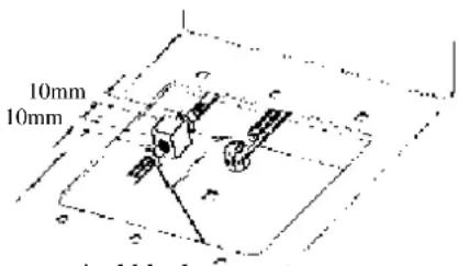
6.10 Clutch rod adjustment
- Move the speed selector lever to the neutral position and unscrew the speed selector knob and remove.
- Remove the transmission gear rack to expose the inside of the chassis by removing the six retaining screws.
- Adjust the nyloc nuts on the clutch rod to give 10mm clearance from the back of the swivel block and 10mm clearance from the front of the swivel block. Figure 6.5.
- Replace the transmission gear rack panel and retain with the six screws, refit the speed selector knob.
text_image
10mm 10mmFigure 6.5 Jockey arm swivel block.
| WARNING | |
| Check operation of cutterhead brake after adjusting cutterhead level, tilt, and low cut setting. |
6.11 Cutterhead Leveling
- Place the ride-on, on a level dry surface, apply the parking brake and remove the ignition key.
- Move the cut height engagement lever to the mid cut or desired cutting height.
- Remove the two cutterhead springs.
4 Loosen the four cutterhead support bolts, allowing cutterhead to slide to the bottom of the slots, and nip up the four bolts. - Raise the front right hand support bolt mid way in it's slot and tighten.
- Fit the two cutterhead springs to the cutterdeck.
- Measure the gap between the blade tip and the ground at the mid point of the cutterhead on one side, then rotate the cutterdisk 180^ to measure the gap on the opposite side of the cutterhead, thereby using the same blade for measurement.
- If is is found that the cutterhead is not level loosen off the front right hand support bolt and adjust accordingly.
- Repeat step 7 and adjust if necessary.
- Tighten all bolts.
- It is also possible to adjust the level by index-adjusting the four cutterhead support bolts.
6.12 Cutterhead Tilt
760mm cutterhead- 15mm from front to back measured over the tips of the blades.
965mm cutterhead- requires no tilt.
- Place the ride-on on a dry level surface.
- Move the cut height engagement lever to the position.
- Measure the tilt of the cutterhead over the blade tips from front to back and check against measurements given.
- Adjust the tilt of the cutterhead as required, by adjusting the two nyloc nuts located on the cutterhead conbars, maintaining a constant spring compression of 36mm measured from the front of the swivel block to the front of the nyloc nut (A). Figure 6.6.
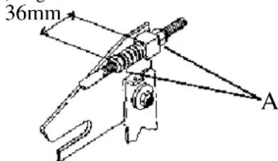
text_image
36mm AFigure 6.6 Cutterhead Conbar
6.13Cutterhead Low cut setting
- Position the machine on a level surface and disconnect the spark plug lead.
-
Move the cutterhead to the low cut position.
-
Adjust the nut (A) on the cutterhead lift rod clearance of 15mm measured at the front of the blade tip circle.
Figure 6.7.

text_image
A B itterhead lift rodFigure 6.7 Cutterhead lift rod
6.14 Cutterhead disengagement
- Move the cut height engagement lever to the high cut position.
- Adjust the nyloc nut (B) Figure 6.7 on the engagement rod till the rollers on the cutterhead engagement arms contact the ramps on the front cutterhead support arms. Figure 6.8
natural_image
Pure mechanical diagram showing a lever mechanism without any text, numbers, or symbolsFig 6.8 Engagement Rollers
6.15 Cutterhead brake adjustment
- Move the cutterhead to the high cut position.
- Loosen the two bolts retaining the brake plate adjust the position of the brake plate to give clearance between the brake pad and the cutterhead 1. pulley.
- Move the cutterhead to the disengaged position to check the operation of the brake.
- Start the engine and move the throttle to position, engage the cutterhead and wait till cutterhead reaches full speed.
- Move the cut height lever to the disengaged position and time the time taken for the cutterhead disc to come to a standstill. The cutterhead should stop within seven seconds.
- If the cutterhead disc takes longer than seven seconds readjust the position of the cutterhead brake plate closer to the cutterhead pulley and recheck as in points 4 and 5.
6.16 Cutterhead brake pad replacement
- Remove the brake plate by removing the two retaining bolts on the side of the chassis for the 760mm cutterhead or remove the brake plate fitted to the top cutterhead on the 965mm cutterhead.
- Drill out the two retaining rivets which hold the Brake pad assembly to the spring plate and discard the old brake pad backing plate.
- The replacement brake pads are fitted with a chemically bonded backing plate, locate this backing plate against the spring plate and retain with two 3/16" rivets. Part No: A2901195.
- Replace the brake plate to the ride-on and check the operation of the cutterhead brake as in Section 6.15 Cutterhead brake adjustments.
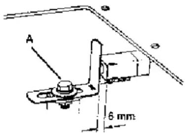
6.17 Steering gear adjustment
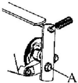
- Loosen the two nuts under the chassis securing the steering shaft pivot block bolts (A). Figure 6.9.
- Move the steering shaft pivot block towards the layshaft and tighten the captive bolt nuts.
- Check that there is no tight spots when turning the steering wheel from lock to lock. Readjust if necessary.

natural_image
Technical line drawing of a mechanical assembly with labeled point A (no text or symbols beyond label)Figure 6.9 Steering pivot block
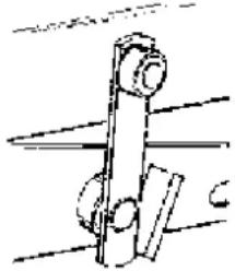
6.18 Safety Interlock adjustment
Clutch brake safety switch
- Depress the clutch brake pedal and lock parking brake on.
- Loosen the spring tab retaining bolt (A) and adjust the position of the spring tab located on the park brake rod, to give a clearance of 6mm between the safety switch body and the spring tab. Figure 6.10
- Tighten the spring tab retaining bolt.
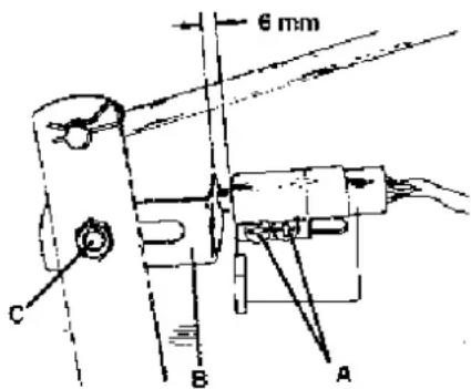
Cutterhead safety switch
give 3mm d 1. Move the cut height engagement lever to the engaged position.
2. Loosen the two safety retaining screws (A) and position the safety switch forward in the mounting bracket slot, Figure 6.11.
the last Tighten the two safety switch retaining screws.
4. Move the cut height engagement lever to the disengaged position.
5. Check that the clearance between the spring tab (B) and the safety switch body is 6mm. If not correct loosen spinning the retaining bolt (C) and position the spring tab to give correct clearance. Tighten the spring tab retaining bolt. Figure 6.11.
text_image
A 6 mmFigure 6.10 Brake clutch safety switch
text_image
6 mm C B AFigure 6.11 Cutterhead safety switch
6.19 Front Axle Beam
Periodically clean and grease the front axle beam pivot area on ride-on chassis. Do not overtighten the two front beam bolts. Beam must be free to pivot in chassis.
6.20 Maintenance Chart
This maintenance chart is to be read in conjunction with the engine manufacturer's instruction manual and information in this Owner's manual
| Engine | Frequency | ||||||
| Each use | First 5 hours | First 20 hours | Every 25 hours | Every 50 hours | Every 100 hours | Every 200 hours | |
| Check oil level | x | ||||||
| Change oil | Briggs | Honda | Tecumseh | Briggs (i) | Honda (i) | ||
| Change oil filter (if fitted) | x | ||||||
| Check air filter elements | x | ||||||
| Clean air filter foam element | x (ii) | ||||||
| Clean air filter paper element | x (ii) | ||||||
| Replace air filter paper element | Tecumseh | x (ii) | |||||
| Check air intake screen | x | ||||||
| Check spark plug | x | ||||||
| Replace spark plug | x | ||||||
| Check battery fluid level | x | ||||||
| Clean battery & terminals | x | ||||||
| Replace fuel filter | x | ||||||
| Ride-On | |||||||
| Check safety interlocks | x | ||||||
| Check cutting blades | x (iii) | ||||||
| Check cutterhead brake | x | ||||||
| Check disc brake | x | ||||||
| Check drive belts | x | ||||||
| Check tyre pressure | x | ||||||
| Remove and clean under pulleys covers. 38" deck only | x | ||||||
| Check for loose fasteners | x | ||||||
| Lubrication points Type of lubricant | |||||||
| Oil jockey arm pivot | Engine oil | x | |||||
| Oil throttle cable | Engine oil | x | |||||
| Oil cutter drive lever | Engine oil | x | |||||
| Oil clutch/brake pedal | Engine oil | x | |||||
| Oil tie rod ends | Engine oil | x | |||||
| Oil drive chains | Chain oil | x | |||||
| Grease stub axles | GP grease | x | |||||
| Grease axle beam | GP grease | x | |||||
| Grease steering shafts | GP grease | x | |||||
Notes:
i - Change the oil every 25 hours when operating the engine under heavy load or in high temperatures refer to engine manufactures instruction manual for correct grade of oil.
ii - Clean the air filter elements more often under dusty conditions or when air borne debris is present. Replace air cleaner parts, if dirty.
iii- Always replace cuttings blades in sets to maintain balance

WARNING
Before undertaking any maintenance, cleaning or adjustments, apply the parking brake and remove the ignition key.
6.21 Electrical schematic
- Rancher model 27169
- Raider model 4056
- Raider model 4083
text_image
Brake switch (Broke engaged) Blade switch (Blades disengaged) GREEN GREEN NO GREEN ④ NC ③ BLUE BLUE NO BLUE BLACK BLACK Tecumseh 13.5hp adaptor Orange Solenoid Alt Engine Starter NC Ignition switch M G S L RED FUSE ⑦ 15 amp 8 9 BLACK Blue Black Tecumseh 13.5 hp adaptor Battery ⑥ + - RED ignition switch Position Circuit OFF G + M Run L + Blank Start S + Blank Note: As per terminal markings Seat switch operator on se ⑪ Item Descriptio 1 Ignition sw 2 Ignition ke 3 Blade swit 4 Brake swit 5 Solenoid 6 Battery 7 Fuse- 15 g 8 Power lead 9 Earth lead- ll. 10 Wiring loc 11 Seat swit| Item | Description | Part Noi |
| 1 | Ignition switch | A07678 |
| 2 | Ignition key | A07679 |
| 3 | Blade switch | A12764 |
| 4 | Brake switch | A12764 |
| 5 | Solenoid | A12586 |
| 6 | Battery | A12017 |
| 7 | Fuse- 15 amp | A07513 |
| 8 | Power lead | A12747 |
| 9 | Earth lead- 11.5 & 13hp | A12748 |
| 9 | Earth lead- 13.5hp | A16388 |
| 10 | Wiring loon | A10531 |
| 11 | Seat switch | A10257 |
| 12 | Tecuseh 13.5hp adaptor | A16385 |
Electrical schematic: Model 27169 Rancher 13Hp OHV B&S AVS Model 4058 Raider 11.5Hp OHV B&S Model 4083 Raider 13.5 Hp OHV Tecumseh
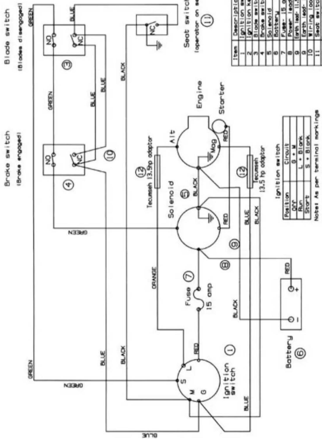
6.22 Electrical schematic- Rancher model 27168 Rancher model 27155

text_image
Brake switch (Brake engaged) Blade switch (Blades disengaged) GREEN GREEN NO GREEN NO BLUE BLUE BLACK ORANGE Adaptor for 15.5 Hp only Solenoid Engine Starter NC Blue S M L Ignition switch Fuse ⑦ 15 amp Black Black Blue Battery ⑥ G RED Yellow To fuel solenoid Ignition switch Position Circuit OFF G + M + Blank Run Blank + B + L Start S + B + L Note: As per terminal markings Seat switch (operator on seat) ⑪ ⑫ ⑬ ⑭ ⑮ ⑯ ⑰ ⑪ ⑫ ⑬ ⑭ ⑮ ⑯ ⑰ ⑪ ⑫ ⑬ ⑭ ⑮ ⑯ ⑰ ⑪ ⑫ ⑬ ⑭ ⑮ ⑯ ⑰ ⑪ ⑫ ⑬ ⑭ ⑮ ⑯ ⑰ ⑪ ⑫ ⑬ ⑭ ⑮ (Continued) Item Description 1 Ignition switch 2 Ignition key 3 Blade switch 4 Brake switch 5 Solenoid 6 Battery 7 Fuse 15 amp 8 Power lead 9 Earth lead 10 Wiring loom 11 Seat switch 12 Loom Adaptor Electrical schematic Model 27169 Rancher 15.5 Hp Intek. Model 27155 Rancher 18 Hp Intek SPV- 60 Sheet: 9 Rev. A 7 April 2 Model: Rancher Selector Page:| Item | Description | Port No: |
| 1 | Ignition switch | A15110 |
| 2 | Ignition key | A07678 |
| 3 | Blade switch | A12784 |
| 4 | Brake switch | A12784 |
| 5 | Solenoid | A12696 |
| 6 | Battery | A12017 |
| 7 | Fuse- 15 amp | A07513 |
| 8 | Power lead | A12747 |
| 9 | Earth lead | A12748 |
| 10 | Wiring loom | A10723 |
| 11 | Seat switch | A10257 |
| 12 | Loom Adaptor | N/A |
| SPV- 60 Sheet: 9 |
| Rev. A 7 April 2004 |
| Model :Rancher Selector Drive |
| Page: |
| PROBLEM | POSSIBLE CAUSES | CORRECTIVE ACTION |
| Engine loses power. | 1. Oil level in crankcase is low.2. Cooling fins and air passages under engine blower housing are blocked.3. Engine load is excessive.4. Air cleaner is dirty.5. Dirt or water is in fuel system.6. Carburettor is adjusted incorrectly.7. Spark plug is pitted, fouled or defective in some other way. | 1. Add oil to crankcase.2. Remove obstruction from passages.3. Select a lower speed to reduce load.4. Clean air cleaner element.5. Have machine serviced by Authorised Service Dealer.6. Adjust the carburettor.7. Install new correctly gapped spark plug. |
| Engine over heats. | 1. Cooling fins and air passages under engine blower housing are blocked.2. Carburettor is adjusted incorrectly.3. Oil level in crankcase is low.4. Engine load is excessive. | 1. Remove obstruction from cooling fins and air passages.2. Adjust the carburettor.3. Add oil to crankcase.4. Select a lower speed to reduce load. |
| Mower vibrates abnormally. | 1. Engine mounting bolts are loose.2. Loose cutter pulley, idler pulley or drive pulley.3. Cutter assembly is unbalanced.4. Cutter assembly is loose. | 1. Tighten mounting bolts.2. Tighten the appropriate pulley.3. Replace broken blades is sets.4. Tighten securing nut. |
| Cutter does not rotate. | 1. Cutter drive belt is worn, loose or broken.2. Cutter drive belt is off pulley. | 1. Install new cutter drive belt.2. Install cutter drive belt. |
| Mower does not drive. | 1. Drive belt is worn, loose or broken.2. Drive belt is off pulley.3. Unable to select forward or reverse. | 1. Install new drive belt.2. Install drive belt.3. Have machine serviced by Authorised Service Dealer. |
| Engine does not start, hard to start, loses power, or fails to keep running. | 1. Fuel tank is empty.2. Speed selected.3. Cutter Drive is engaged.4. Spark plug is loose.5. Spark plug lead is loose or disconnected from spark plug.6. Spark plug gap is incorrect.7. Spark plug is pitted, fouled or defective in some other way.8. Wrong spark plug is used.9. Electrical connections are loose.10.Carburettor is adjusted incorrectly. 10.Adjust 11.Air cleaner is dirty.12.Vent hole in fuel tank is blocked.13.Dirt or water in fuel system.14.Dead battery.15.Defective Electronic Ignition System.16.Defective Safety Switches. | 1. Fill fuel tank with petrol.2. Select Neutral.3. Disengage Cutter Drive.4. Tighten spark plug.5. Install spark plug lead on spark plug.6. Set gap between electrodes at 0.7mm to 0.8mm.7. Install new correctly gapped spark plug.8. Install correct spark plug.9. Check electrical system to ensure good contact.the carburettor11.Clean the air cleaner element.12.Inspect and open vent.13.Have machine serviced by Authorised Service Dealer. |
| Engine does not idle or idles poorly | 1. Air cleaner is dirty.2. Oil level in crankcase is low.3. Cooling fins and air passages under engine blower housing are blocksed.4. Idle speed is too low or high.5. Dirt or water is in fuel system.6. Vent hole in fuel tank is blocked.7. Spark plug is pitted fouled or defective in some other way. | 1. Clean air cleaner element.2. Add oil to crankcase.3. Remove obstruction from cooling passages.4. Adjust the carburettor.5. Have machine serviced by Authorised Service Dealer.6. Clean fuel tank vent.7. Install new correctly gapped spark plug. |
WARRANTY
General
- Rover Mowers Limited warrant this machine or accessory is free of defects in material and workmanship.
- Claims are limited to making good or replacing any part found defective by the manufacturer or his agent.
- The warranty period shall apply from the date of purchase for a period of:
- 12 months for domestic use
- 90 days for commercial use
- Warranty applies to Australia and New Zealand only.
EXTENDED WARRANTY: For domestic use only, a 24 month extended warranty applies. It requires the customer to complete the '2 Year warranty registration card', and forward along with a copy of the cash register receipt to "Warranty, Rover Mowers Limited". Normal warranty exclusions as listed still apply.
Exclusions

A list of conditions excluded from warranty follows:
- Engines other than Suzuki products.
- Parts considered suffering from wear and tear.
- Parts damaged due to abuse or misuse.
- Parts that can be subjected to use beyond their normal intended working capacity e.g. blades, blade bolts, v-belts and spark plugs.
- If repairs or alterations have been made without the manufacturer's written authority.
- Any transport costs involved in the repair or replacement of any defective part.
- If it is found that parts other than genuine have been used on the machine.
NB This warranty does not exclude any conditions or warranty implied by the Trade Practices Act 1974 or any other relevant legislation.
Engines other than Suzuki are warranted by the engine manufacturer and could differ from the warranty of the rest of the machine.
Refer to the engine manual (if included) or consult the nearest engine service dealer.
Proof of date of purchase should be retained as it needs to be presented if warranty is to be claimed. Fill out the details in the following table as a record for warranty purposes.
| Dealer | Product |
| • Name: | • Model number: |
| • Address: | • Serial number: |
| • Phone No: | • Date of purchase: |

Rover Mowers Limited reserves the right to make changes and add improvements to its products at any time without notice or obligation.
The company reserves the right to discontinue manufacture of any product at any time to its discretion.


Rover Mowers Limited
PO Box 1235
Eagle Farm
Queensland 4009
AUSTRALIA
Rover Mowers Limited
East Tamaki
Auckland
NEW ZEALAND

Printed in Australia on RECYCLED PAPER as a sign of Rover Mower's commitment to greening Australia and New Zealand.

GWAIL