Challenger SP Mulch 'N Catch - Lawn mower Rover - Free user manual and instructions
Find the device manual for free Challenger SP Mulch 'N Catch Rover in PDF.

User questions about Challenger SP Mulch 'N Catch Rover
0 question about this device. Answer the ones you know or ask your own.
Ask a new question about this device
Download the instructions for your Lawn mower in PDF format for free! Find your manual Challenger SP Mulch 'N Catch - Rover and take your electronic device back in hand. On this page are published all the documents necessary for the use of your device. Challenger SP Mulch 'N Catch by Rover.
USER MANUAL Challenger SP Mulch 'N Catch Rover
DOMESTIC ROTARY LAWNMOWER OWNER'S MANUAL

natural_image
Abstract geometric shape with a diagonal division on a plain background (no text or symbols)MAINTENANCE - Powerstart mowers (only) (continued) - refer figure 19
Battery Charging
A new battery when supplied with the mower may not be fully charged to maximum capacity. The battery should have an initial charging period of 10 to 16 hours. To charge the battery it must be removed from the mower first.

CAUTION
Use only an approved battery charger supplied by the mower dealer which has been designed for use with this battery.
- Connect the battery charger to the battery with the red lead (positive) to the positive (+) terminal of the battery and the black lead (negative) to the negative (-) terminal of the battery.
- Connect the battery charger to a suitable mains power outlet and switch on.
- When charging is complete after 10 to 16 hours, switch off the power outlet and disconnect the battery charger from the power outlet.
- Disconnect the battery charger leads from the battery and refit the battery to the mower.

natural_image
Sketch of a robotic arm gripping a rectangular object, no text or symbols presentFigure 19. Battery
Care and Handling
- Do not disassemble the battery, as it's strong acid electrolyte may burn your skin or clothes.
- Do not short out the battery terminals, as this may burn the terminals and cause damage to the equipment.
• Do not incinerate the battery to dispose of it. The battery may explode if exposed to fire. - Clean the battery with a dry cloth only, never use oil, petrol, thinners or any other petrochemical.
- Handle the battery with care. If the battery is dropped and the case is damaged the acid electrolyte (sulphuric acid) may leak out. Wipe up leaking acid with a cloth and neutralise acid with an alkaline solution.
- In the event of electrolyte coming into contact with the skin, immediately flush with water and seek medical attention.

CAUTION
Do not disassemble the battery. Its strong acid electrolyte may burn your skin or clothes.
SAFETY INSTRUCTIONS
- Never mow while barefoot or wearing open sandals or thongs. Wear long trousers and heavy shoes.
- Know your controls. Read the owner's manual carefully. Learn how to stop the engine quickly in any emergency.
- Make sure the lawn is clear of sticks, stones, bones, wire and debris. They could be thrown by the blade.
- Stop the engine and disconnect the spark plug wire before clearing blockages, checking, or working on the mower.
- Before using, always visually inspect to see that blades, blade bolts and cutter assembly are not worn or damaged. Replace worn or damaged blades in sets to preserve balance.
DAMAGED BLADES AND WORN BOLTS ARE MAJOR HAZARDS.
- Check all nuts, bolts and screws often; always be sure the mower is in a safe operating condition. Use only genuine replacement parts.
- Refuel outdoors only. Do not smoke while fuelling engine. Add fuel before starting the engine. Never remove the cap off the fuel tank or add fuel while the engine is running or the engine is hot. If fuel is spilled, do not attempt to start the engine but move the machine away from the area of the spill and avoid creating any source of ignition until fuel vapours have dissipated.
- Do not mow whilst people, especially children or pets are in the mowing area.
- Replace worn or faulty silencers (muffler)
• Mow only in good daylight. - Never use the mower unless the grass catcher or guards (rear flap) provided by the manufacturer are in position.
- Start the engine carefully with feet well away from the blade.
- Do not operate the engine in a confined space where exhaust fumes (carbon monoxide) can collect.
- Stop the engine whenever you leave the mower, even for a moment.
- Do not allow children or people unfamiliar with these instructions to use the mower.
- Store the mower in a well-ventilated room away from naked flames such as may be found in hot water heaters.
- Do not over-speed the engine or alter governor settings. Excessive speed is dangerous and shortens the mower life.
- It is advisable to wear suitable eye protection when operating a mower.
- Store fuel in a cool place in a container specifically designed for the purpose. In general, plastic containers are unsuitable.
- Stop the engine, disconnect the spark plug wire and inspect the mower if: a) the mower begins to vibrate abnormally; or b) after striking a foreign object.
- Never cut grass while walking backwards.
- Stop the engine before pushing the mower across gravel drives, walks or roads.
- Walk, never run.
- Mow across the face of slopes, never up and down. Exercise extreme caution when changing direction on slopes. Do not mow excessively steep slopes.
- Never pick up or carry a mower when it is operating.

CAUTION
To avoid engine damage drain the oil and fuel from the engine before turning the lawnmower over in any direction.
INTRODUCTION
Congratulations on your purchase of this domestic rotary lawnmower.
This manual covers the setting up, operation and maintenance of the domestic rotary lawnmower. Please read and understand this owner's manual before using the mower. If any point is unclear, contact MTD Products Aust or any authorised service dealer or agent.
To emphasise special information the following WARNING and CAUTION highlights are used.

WARNING
The safety of the user and others involved. Personal injury may result should this information be disregarded.

CAUTION
Follow these instructions to avoid mower damage and possible loss of warranty.
MANUAL CONTENTS
| Know Your Lawn Mower | 1 |
| Safety instructions | 2 |
| Introduction | 3 |
| Setting up | 4 & 5 |
| Operation - All Models | 4, 5 & 6 |
| - Mulch Models (only) | 5 & 6 |
| Maintenance - All Models | 7, 8 & 9 |
| - Self Propelled Models (only) | 9 & 10 |
| - Powerstart Models (only) | 10 & 11 |
| - Mulch Models (only) | 12 |
| Mulch Mowing Information | 12 & 13 |
| Warranty conditions | 15 |
CARTON CONTENTS:
Quantity
• Domestic rotary lawnmower 1
- Plastic kit bag (containing Owner's Manual, Engine Owner's Manual, Spark Plug Spanner Kit, Grass Catcher pins, Cable Tie 1 NB. Kit may vary for different mower models
• Plastic grass catcher upper half 1
• Plastic grass catcher lower half 1
• Assembly instructions 2
NB. Models which have Grass Catcher attachments will have the attachments in the carton. NB. Mowers which have the Mulch option will have the mulch plug fitted into the rear chute of the mower.
If when unpacking your new lawnmower it is found that there are items missing contact your nearest authorised MTD Products Australia service dealer or agent.
SETTING UP
Engine oil
Oil must be added before attempting to start the engine otherwise damage to the engine will occur.
Refer to the engine owner's manual.
The 4 stroke engine fitted to the lawnmower is shipped with no oil in the sump.
Engine fuel
Refer to the engine owner's manual.
Use only fresh unleaded fuel in the lawnmower engine.
Adjusting the cut height— refer figure 1.

WARNING
When selecting the cut height stand to the rear of the machine with your feet well clear of the cutting blades.
The 10 lawnmower height settings are controlled by the height adjustment lever located at the rear right hand wheel.
- Grasp the height adjustment lever (1) and pull the lever away from the base to disengage the lever from the height adjustment rack (2).
- Move the lever either forwards or backwards to the desired position and release the lever so as to engage in the height adjustment rack.
(2) (1)
natural_image
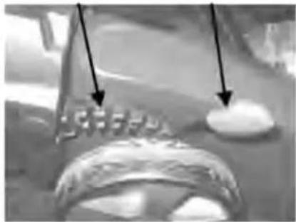
Close-up of a mechanical component with two arrows pointing to features (no visible text or symbols)Installing the grass catcher – refer
figures 2 and 3.
Figure 1. Height adjustment

WARNING
The grass catcher should only be fitted or removed when the engine is stopped. Never raise the rear flap when the engine is running.
- Raise the rear flap of the mower.
- Grasp the grass catcher by the top handle and position the grass catcher against the rear of the mower. Refer to Figure 2.
- Locate the grass catcher above the grass catcher support bracket. Align the catcher lugs with the hooks each side and lower the catcher into place.
- Lower the rear flap so that the back edge of the rear flap hooks over the matching lip on the grass catcher. Refer to Figure 2.
natural_image
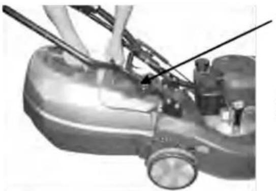
Close-up of a mechanical device with visible components and wiring (no text or symbols)Rear Flap
Grass Catcher
Support Bracket

natural_image
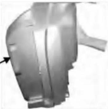
Close-up of mechanical components with no visible text or symbolsFigure 2. Grass catcher fitment
Figure 3. Grass catcher hooks
Removing the grass catcher
- Raise the rear flap of the mower to release the grass catcher.
- Lift the grass catcher clear of the mower and lower the rear flap.
Emptying the grass catcher - refer figure 4, 5, 6.
Remove the grass catcher (as per instructions above).
Standard Grass Catcher
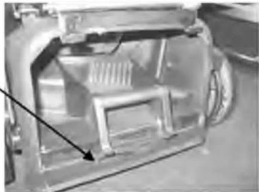
• Tilt the grass catcher with the opening downwards.
- Grip the catcher top and side handle of the grass catcher and shake the clippings out. Refer to figure 4.
Rear Opening Grass Catcher
• Tilt the grass catcher with the opening upwards.
- Grip catcher top and side handle and Press Trigger button on catcher handle and open grass catcher. Refer figure 5 and 6.
Side
Handle
natural_image
Metallic mechanical component with a black arrow pointing to a feature (no visible text or symbols)Figure 4. Emptying standard grass catcher
Adjustable Air Vents— Adjustable Air Vents can be closed to minimise dust. The air vents can only be closed one side at a time. Note: For best grass catching performance both vents must be open

text_image
Adjustable air vents Trigger-release buttonFigure 5. Trigger-release button

natural_image
Two metallic USB flash drives overlapping, no visible text or symbolsFigure 6. Emptying trigger-release grass catcher
Drive engagement - Self propelled mowers (only)
• Start the engine and set the engine speed to the required grass cutting speed.
- Push forward on the clutch engagement lever to engage the self-propelled drive to the rear wheel.
- To disengage the self-propelled drive release the engagement lever and allow it to return to the disengage position.

WARNING
The mulch plug should only be fitted or removed when the engine is stopped. Never raise the rear flap when the engine is running.
OPERATION - Mulch Mowers (only) Installing the Mulch Plug
- With the engine stopped, raise the rear flap of the mower and remove the grass catcher (if fitted).
- Insert the long right hand side of the mulch plug first into the rear chute of the mower. Refer to figure 7.
- Rotate the left hand side into the rear chute of the mower and push it as far forward as possible.
- Lower the mulch plug onto the rear ramp and lock mulch plug in over the rear ramp lug (1). Refer figure 8.
- Lower the rear flap.

natural_image
Close-up of a car's front bumper showing the hood and seat area (no visible text or symbols)Figure 7. Mulch plug installation (A)
OPERATION - Mulch Mowers (only) Removing the Mulch Plug
- With the engine stopped, raise the rear flap of the mower.
- Grasp the rear of the mulch plug and lift the mulch plug over the rear ramp lug (1). Refer figure 8.
- Guide the mulch plug out by rotating the shorter left hand side to the right and then guiding the longer right hand section until clear of the mower. Refer to figure 7.
natural_image
Close-up of a car's internal structural components, possibly engine or chassis frame, with no visible text or symbols.Figure 8. Mulch plug installation (B)
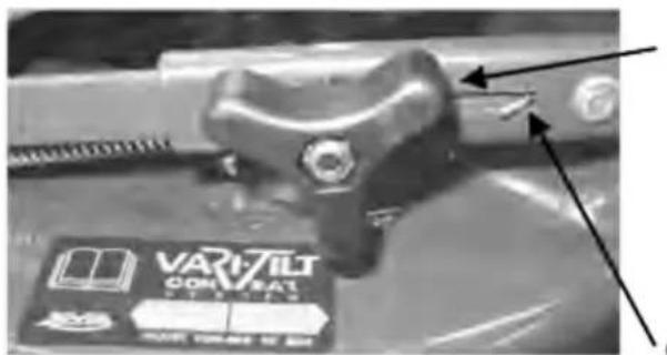
Vari-Tilt Conbar Mowers (only) - Information
The Rover Vari-tilt System (Patent Pending) is fitted to provide improved performance when mulching. Generally it
is recommended that the conbar is at its longest length for Mulch mowing and at it's shortest length for Catch mowing (Refer to figures 9 & 10). The conbar at it's longest length also provides a greater maximum height of cut.
Vari-Tilt Conbar Mowers (only) - Adjustment for grass catching
 | WARNING |
| When adjusting the Vari-tilt conbar, the engine must be stopped and your feet and hands kept well clear of the cutting blades. |
- With the engine stopped, move the height adjustment lever (1) to the high cut position (refer to figure 1).
- Loosen the conbar locking knob (A).
- Apply downward pressure to the top of the front nose of the mower base so that the gap in the conbar is at it's shortest. Refer to figure 9.
- Maintain pressure on the front of the mower base and tighten the conbar locking knob in this position.
Vari-Tilt Conbar Mowers (only) - Adjustment for mulch mowing
- With the engine stopped, move the height adjustment lever (1) to the high cut position (refer to figure 1).
- Loosen the conbar locking knob (A).
- Apply downward pressure to the handlebar to tilt the mower back so that the conbar is at it's longest. Refer to figure 10.
- Maintain downward pressure on the handle bar and tighten the conbar locking knob in this position.
text_image
VARI-TILT CONVEBAT 2018-10-04 12:30Figure 9. Vari-tilt conbar - adjusted to the grass catching position

text_image
(A) VARI TUT CON. BART GAP INFigure 10. Vari-tilt conbar - adjusted to the mulch mowing position
OPERATION
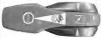
NOTE: Throttle Control is only fitted to certain model mowers
Throttle Control marked for 'Stop' O, 'Start' | and
'Run' positions. Refer figures 11 and 12.
To Start the engine
Move the Blade Control Lever towards the handle bars before starting engine.
Refer to the engine owner's manual for detailed starting procedure.
Ensure that the engine oil is at the correct level and that the fuel tank is unleaded fuel.
natural_image
Close-up of a mechanical tool or grip component (no visible text or symbols)Figure 11. Throttle Control - "START" Position

Powerstart mowers only
Turn the key to on (I) position to engage the electric starter. Release the key when the engine starts and allow to return to the off (O) position.
natural_image
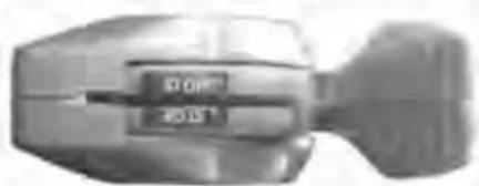
Close-up of a mechanical component with no visible text or symbolsFigure 12. Throttle Control - "STOP" Position
To Stop the engine
Move the throttle control lever (If Fiited) to the "Slow/ Stop" position and release the Blade Control Lever.
Wait till the engine comes to a complete stop before removing or fitting the grass catcher or mulch plug to the mower, or attempting any maintenance work on the mower.

WARNING
Before carrying out any maintenance on the mower remove the spark plug lead from the spark plug to prevent accidental starting.
MAINTENANCE - All mowers
Engine air cleaner
Refer to the engine owner's manual for detailed maintenance instructions.
Replace immediately if the element is damaged.
Snorkel air cleaner - refer figure 13.
The snorkel air cleaner must be serviced after each 50 hours of normal mowing. The element must be serviced more regularly if the mower is used in dusty conditions.

natural_image
Close-up of a mechanical component with metallic parts and a cylindrical shaft (no visible text or symbols)Figure 13. Snorkel air cleaner
- Disconnect the air tube from the element holder and remove the holder cap.
- Remove the cartridge and tap gently on a flat surface to

CAUTION
Do not allow dirt to enter the air tube, engine damage may occur. Check the condition of the air tube regularly and replace if damaged.
remove dirt.
- Replace element in holder and replace holder cap.
- Replace the air tube to the bottom of the element holder.
Spark plug
Refer to the engine owner's manual for detailed maintenance instructions.
Muffler
Check the condition of the muffler periodically for rust and cracks. Replace if found to be damaged as this can lead to increased exhaust noise. Replace only with a genuine original equipment part.
Blades - refer figure 14.
 | WARNING |
| Always ensure the engine is stopped and the spark plug lead is removed before attempting any maintenance on the mower.Secure the mower safely when tilted upwards to access the underside. |
Check the condition of the blades and central fasteners at regular intervals, or after striking a solid object, or if the mower begins to vibrate abnormally. The blades with use, will lose their sharp edge and the quality of the grass finish will deteriorate. When this happens, all the blades should be removed and replaced with a new set of blades. Always use genuine replacement blades and only replace blades in sets to maintain balance.
Cutting Assembly
- With the engine stopped, remove the spark plug lead and grass catcher or mulch plug.
- Set the height of cut lever to the high cut position, and fold the handle bars.
- Tilt the mower so the spark plug is up.
- Inspect the cutting assembly for damage and wear.
- Check the disc retaining bolts. Tighten the centre bolt to 57-62Nm.
- Return the mower to its normal position and re-attach the spark plug lead.
Blade Change - refer figure 14.
 | WARNING |
| Always ensure the engine is stopped and the spark plug lead is removed before attempting any maintenance on the mower.Always replace blades and blade fixings in complete sets to maintain balance. |
- With the engine stopped, spark plug lead and grass catcher or mulch plug removed, open the discharge flap and prop in the open position.
- Set the mower to the high cut position and fold the handle bar down.
- Rotate the cutting assembly carefully to access the blade retaining bolts.
- Using gloves and a suitable spanner, remove the blade assembly.
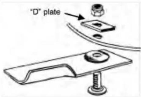
- Retain the "D" plates and discard the blades and fasteners. NB. Mowers fitted with a circular cutting disc must be fitted with a "D" Plate (as shown in figure 14). These parts are available from any authorised service dealer or agent.
• Fit new blades and fasten in the correct order.
- Tighten the blade retaining nuts firmly to 16Nm.
- Remove the flap prop, close the discharge flap and re-attach the spark plug lead.
text_image
"D" plateFigure 14. Blade Attachments
Cleaning
To ensure safe operation and long life it is recommended to clean the mower after every use. This will prevent corrosion, overheating and fire risk while ensuring ultimate performance.
Washport (where fitted) - refer figure 15
- Place the mower outdoors on a flat surface.
- Set the height to maximum.
- With the engine stopped connect a garden hose with a snap on connection, to the washport fitted to the inside face of the cutting chamber.
- Turn the garden hose on.
- Return to the mower and start the engine and run at full speed for 1 minute.
- Stop the engine and turn off the garden hose.
- Remove the garden hose from the washport.
- Inspect the underside of the mower, if not completely clean use garden hose to flush out remaining debris.

natural_image
Close-up of mechanical components including a threaded bolt and valve assembly (no visible text or symbols)Figure 15. Washport Connection
Cleaning the Underside of the Mower
 | CAUTION |
| Always ensure the engine is stopped and the spark plug lead is removed before attempting any maintenance on the mower. |
- Place the mower outdoors on a flat surface.
- Set the cut height to maximum.
- With the engine stopped, remove the grass catcher or mulch plug and lift open the discharge flap.
- Use a garden hose to wash out all the grass clippings.
- Inspect the underside and repeat the cycle if still not clean.
Cleaning the Upper side of the Mower
- Use a dry cloth or soft brush to remove all loose clippings.
- Use a damp cloth with mild detergent to clean away oil or other grime.
- Wash the grass catcher and/or mulch plug separately from the mower with a hose. Wash all clippings out of the inside, outside and from the grass catcher mesh.
- Let the mower dry before storing.
| CAUTION |
| Do not hose the engine as water can damage the air cleaner and ignition system. |
MAINTENANCE - Self-Propelled mowers (only)
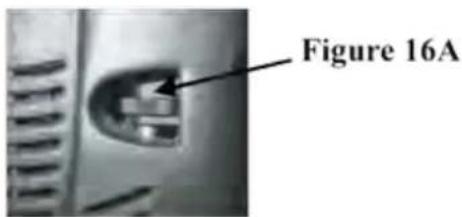
Clutch adjustment - refer figure 16.
- Remove the 6 screws from the control console and remove front cover.
- Rotate thumb wheel anti-clockwise until the clutch spring extends to 90mm from end to end when the drive bale is engaged. (Refer Figure 16A)
• Refit the front panel of the control console.
Belt adjustment
• The drive belt is automatically tensioned by the tensioning spring and does not require adjustment.
text_image
Figure 16A
text_image
90mmFigure 16. Clutch spring
MAINTENANCE - Self-Propelled mowers (only)
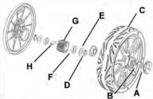
Drive wheel cleaning and drive pawl lubrication - refer figure 17 and 18 Every 50 hours:-
• Disconnect spark plug lead.
• Support the rear wheels off the ground and remove the wheel caps (A).
- Remove the nyloc nut (B) retaining the wheel (C) to the axle.
- Remove the wheel (C) from the axle and clean the inside of the wheel hub.
- Remove the circlip (D), outer washer (E), outer bush (F), pinion gear (G) and pawl (h) from the drive shaft (recording the orientation of the pinion gear and the pawl to ensure correct reinstallation).
• Clean all components.
- Lightly grease the pawl (H), the slot in the shaft, bushes (F) and the inside of the pinion gear (G) with light general purpose grease then refit the components onto the drive shaft in the correct orientation, retaining them with the circlip (D).
text_image
Diagram of a bicycle wheel assembly with labeled components A through HFigure 17. Rear drive wheels
natural_image
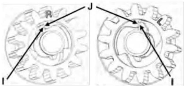
Two mechanical gear diagrams showing rotational motion with arrows indicating direction (no text or symbols)Figure 18. Rear wheel pinions and pawls
NOTE: The pinion gear (G) is marked "R" on one side and "L" on the other. The pinion gear
(G) is to be fitted with the 'R' displayed when fitted on the right hand drive side of the mower and with the "L" displayed when fitted on the left hand drive side. Refer to figure (18). The right and left side of the mower is indicated while standing in the operator position.
NOTE: The pawl must always be orientated so that the side with the large flat face (i) will come in contact with the flat faces inside the pinion gear (j). The orientation is important to ensure that the pawl will drive the pinion gear when the clutch is engaged. Refer to figure (18).
- Refit the wheel and nyloc nut (B). Tension nut just enough to remove the side to side movement of the wheel.
• Refit the wheel caps (A) and the spark plug lead and lower the wheels to the ground.
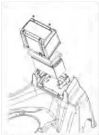
MAINTENANCE - Powerstart mowers (only) - refer figure 19
Battery Removal
- Remove the four retaining screws from the battery cover.
- Remove the battery from the rubber blocks and simultaneously disconnect the wiring loom from the battery terminals.
Battery Installation
- Connect the mower wiring loom to the battery with the red lead attached to the positive (+) terminal of the battery and the black lead to the negative (-) terminal of the battery.
- Place the battery into the rubber blocks with the battery terminals closest to left-hand side when viewed from behind the mower.
• Refit the battery cover and retain with the four screws.
MAINTENANCE - Powerstart mowers (only) (continued) - refer figure 19
Battery Charging
A new battery when supplied with the mower may not be fully charged to maximum capacity. The battery should have an initial charging period of 10 to 16 hours. To charge the battery it must be removed from the mower first.

CAUTION
Use only an approved battery charger supplied by the mower dealer which has been designed for use with this battery.
- Connect the battery charger to the battery with the red lead (positive) to the positive (+) terminal of the battery and the black lead (negative) to the negative (-) terminal of the battery.
- Connect the battery charger to a suitable mains power outlet and switch on.
- When charging is complete after 10 to 16 hours, switch off the power outlet and disconnect the battery charger from the power outlet.
- Disconnect the battery charger leads from the battery and refit the battery to the mower.
natural_image
Sketch of a robotic arm gripping a rectangular object, no text or symbols presentFigure 19. Battery
Care and Handling
- Do not disassemble the battery, as it's strong acid electrolyte may burn your skin or clothes.
- Do not short out the battery terminals, as this may burn the terminals and cause damage to the equipment.
• Do not incinerate the battery to dispose of it. The battery may explode if exposed to fire. - Clean the battery with a dry cloth only, never use oil, petrol, thinners or any other petrochemical.
- Handle the battery with care. If the battery is dropped and the case is damaged the acid electrolyte (sulphuric acid) may leak out. Wipe up leaking acid with a cloth and neutralise acid with an alkaline solution.
- In the event of electrolyte coming into contact with the skin, immediately flush with water and seek medical attention.

CAUTION
Do not disassemble the battery. Its strong acid electrolyte may burn your skin or clothes.
MAINTENANCE - Mulch mowers (only)
Mulching Equipment
For optimum mulching performance
• The mulch blades are to be kept sharp.
- Maintain the blade sharpening angle when sharpening.
- Keep the cutting edge feather free when sharpening.
- Keep the underside of the mower deck and the mulch plug free of build-up.
• Refer to the "Cleaning" section on page 7 and 8.
MULCH MOWING INFORMATION
Some mowers are fitted with an option for mulch mowing.
A mulch plug is supplied with these mowers and it is installed in the rear discharge chute (as noted in the "OPERATION" section of this manual) to perform mulch mowing.
The following information provides advice on mulch mowing.
MULCH MOWING
The mulch mowing setup reduces the grass clippings into very fine particles.
The design allows for the even distribution of the grass particles at the base of the lawn.
The mulched clippings can then:
• Break down quickly, releasing nutrients into the soil, saving on fertilizer costs.
- Reduce evaporation of moisture from the soil which reduces watering costs and effort.
• Help to control temperature extremes protecting the roots of the grass.
• Assist in controlling soil erosion.
BENEFITS TO YOUR LAWN
Research has shown that lawns are usually cut too short,
Grass, like any other plant life, relies on photosynthesis to regenerate and survive.
Reduced leaf size (from cutting too low) can seriously effect a lawn by:
• Making it easy prey for disease.
• Encouraging weeds to take hold.
• Exposing the soil to:
- greater evaporation
- temperature extremes; and
- erosion
Raising the cut height and Mulch mowing follows the best practice for nurturing a healthier more attractive lawn with less water usage.
MULCH MOWING INFORMATION (continued) BENEFITS FOR YOU
Because you mulch as you mow the time and cost savings are also significant:
- Eliminating raking of leaves before mowing (Mulch mowing picks up and converts fallen leaves into mulch).
• Eliminating raking of cut grass.
• Saves time spent emptying the catcher.
• Automatically disposing of grass clippings. - Eliminating the need to dispose of clippings at the refuse tip.
USEFUL MULCH MOWING TIPS
Mulch mowing is an art form and to produce the best results consistently, follow these useful hints:
• Do not attempt to mulch if the grass is too wet.
Wet grass tends to clump together and does not evenly spread out.
It also clogs up the underside of the base.
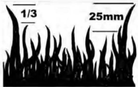
• Do not mulch mow on too low a cutting height.
Remember the maximum cut should be 25mm off the top of the grass, or 1/3rd the grass (blade) height, whichever is the lesser amount. Refer to figure 20.
• Do not push the mower too fast.
To obtain the best finish it may be necessary to regulate the ground speed.
• Run the engine at full throttle.
Running the engine at low speed does not allow the blades to mulch the grass efficiently.
- Keep the mulch blades sharp.
The mulch blades are designed to cut and re-cut the blades of grass.
text_image
1/3 25mmFigure 20. Grass height
If the mulch blades are not kept sharp, mulching performance will be reduced.
- Keep the underside of the mower and mulch plug clean.
Build-up of grass under the mower base blocks the airflow created by the mulch blade and reduces the mulching performance.
If the conditions for mulch mowing are not ideal and some clipping trails are visible after cutting it may be necessary to:
- Fit the grass catcher and catch mow.
- Re-mow over the visible clippings.
- Raise the cut height.
- Rake the clippings up after mowing.
NOTES
Warranty Conditions
Australia Only
(Not applicable to other International Regions)
MTD Products Australia warrant that this machine is free from defects in material and workmanship. This warranty is limited to making good or replacing any part which appears upon inspection by the manufacturer or his agent to be defective in material or workmanship.
The warranty for the engine used to power this machine may differ from the warranty for the other components. Refer to the engine warranty statement in the Engine Owner's Manual which has been included with this machine. As the warranty may differ, you are advised to read the engine warranty carefully.
For other items this warranty shall apply for a period of 2 years from date of purchase for domestic use only. Warranty for commercial or industrial use is 90 days from date of purchase.
This warranty does not obligate the manufacturer, his agents or dealers to bear the transport costs incurred in the repair or replacement of any defective part. This warranty excludes fair wear and tear, or any damage caused by misuse or abuse. Parts such as blades, blade bolts, V-belts, and spark plugs, which can be subjected to use beyond their normal intended working capacity are also excluded.
This warranty is void if parts other than genuine have been used or if repairs or alterations have been made without the manufacturer's written authority. The above warranty does not exclude any condition or warranty implied by the Trade Practices Act 1974 or any other relevant legislation which implies any condition which cannot be excluded.
REMEMBER:
PROOF OF PURCHASE IS THE RESPONSIBILITY OF THE OWNER AND IS RECOMMENDED PRIOR TO WARRANTY WORK BEING UNDERTAKEN. REPAIRS MUST BE CARRIED OUT BY AN AUTHORISED DEALER OR AGENT AND GENUINE SPARE PARTS MUST BE USED OR YOUR WARRANTY WILL BE VOID.
MTD Products Australia reserves the right to make changes and add improvements to its product at any time without notice or obligation. The Company also reserves the right to discontinue manufacture of any product at its discretion at any time.
Online warranty registration:
www.rovermowers.com.au
For your Record:
Retailers Name: Address:
Phone No: Model No:
Serial No: Date of Purchase

text_image
MTD For a Growing WorldA.B.N. 96 004 873 572
MTD Products Australia Pty Ltd. PO. Box 376 Dandenong. Vic. Australia. 3175
Customer Service Phone: Number: 07 3213 0233
04016785
Revision 19.4.2011
© Copyright
2011