RB 24EAP - Blower HITACHI - Free user manual and instructions
Find the device manual for free RB 24EAP HITACHI in PDF.
| Product Type | Gas Blower |
| Brand | Hitachi |
| Model | RB 24EAP |
| Displacement | 23.9 ml |
| Dry Weight | 3.9 kg |
| Fuel Tank Capacity | 0.52 l |
| Spark Plug | NGK BMR7A |
| Sound Power Level (LwA) | 109 dB(A) |
| Sound Pressure Level (LpA) | 87 dB(A) (CEN) |
| Vibration Level | 12 m/s² |
| Engine | 2-stroke, air-cooled |
| Fuel | Mixture of unleaded gasoline (89 octane) and 2-stroke oil (25:1 to 50:1) |
| Idle Speed | 2800-3200 rpm |
| Spark Plug Gap | 0.6 mm |
| Safety Distance | 15 meters |
| Included Accessories | Straight tube, tapered tube, combination wrench |
| Safety Features | On/Off switch, protective guard, anti-vibration system |
| Routine Maintenance | Cleaning air filter, fuel filter, spark plug, cooling fins |
| Intended Use | Blowing leaves, grass, gravel and light debris |
Frequently Asked Questions - RB 24EAP HITACHI
User questions about RB 24EAP HITACHI
0 question about this device. Answer the ones you know or ask your own.
Ask a new question about this device
Download the instructions for your Blower in PDF format for free! Find your manual RB 24EAP - HITACHI and take your electronic device back in hand. On this page are published all the documents necessary for the use of your device. RB 24EAP by HITACHI.
USER MANUAL RB 24EAP HITACHI
Read the manual carefully before operating this machine.
text_image
1 ① ② ③ 1 2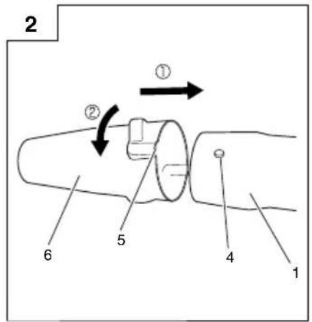
text_image
2 ① ② 5 6 4 1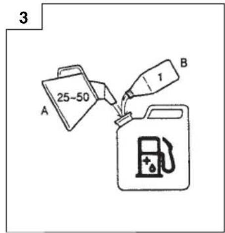
text_image
3 A 25~50 B T
text_image
4 7 ON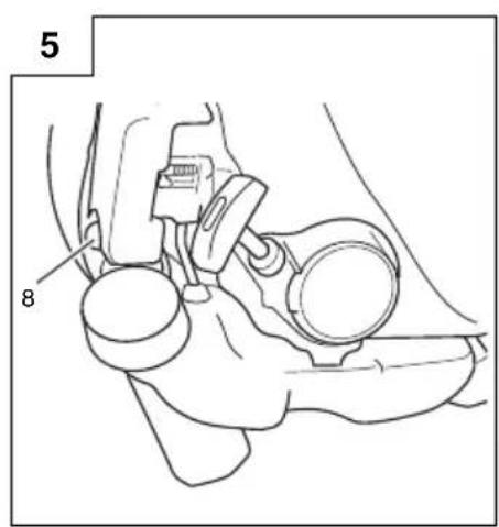
text_image
5 8
text_image
RUN (OPFN) CI OSFD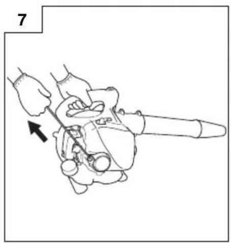
natural_image
Line drawing of a hand using a tool to adjust a mechanical component (no text or symbols)
natural_image
Line drawing of a person using a handheld power tool to clean or exhaust air (no text or symbols)
text_image
OFF 7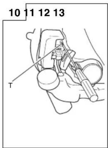
text_image
10 11 12 13 T
natural_image
Technical line drawing of a mechanical device with internal components (no text or symbols)
natural_image
Line drawing of a mechanical assembly with no visible text or symbols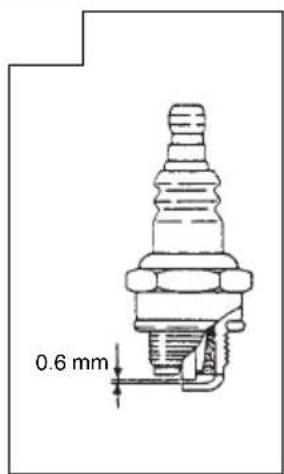
text_image
0.6 mmMEANINGS OF SYMBOLS
NOTE: Some units do not carry them.
| Symbols⚠ WARNINGThe following show symbols used for the machine. Be sure that you understand their meaning before use. | |||
 | It is important that you read, fully understand and observe the following safety precautions and warnings. Careless or improper use of the unit may cause serious or fatal injury. |  | WARNING △DANGERHot surfaces; The muffl er and surrounding cover may become extremely hot. Always keep clear of exhaust and muffl er area, otherwise serious personal injury may occur. |
 | Read, understand and follow all warnings and instructions in this manual and on the unit. |  | Keep all children, bystanders and helpers 15 m away from the unit. If anyone approaches you, stop the engine immediately. |
 | Always wear eye, head and ear protectors when using this unit. |  | Use anti-slip and sturdy footwear. |
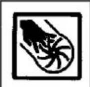 | WARNING △DANGERKeep hands off from rotating fan. | ||
Contents
WHAT IS WHAT ....3
WARNINGS AND SAFETY INSTRUCTIONS ....4
SPECIFICATIONS 5
ASSEMBLY PROCEDURES 5
OPERATING PROCEDURES ....5
MAINTENANCE....6
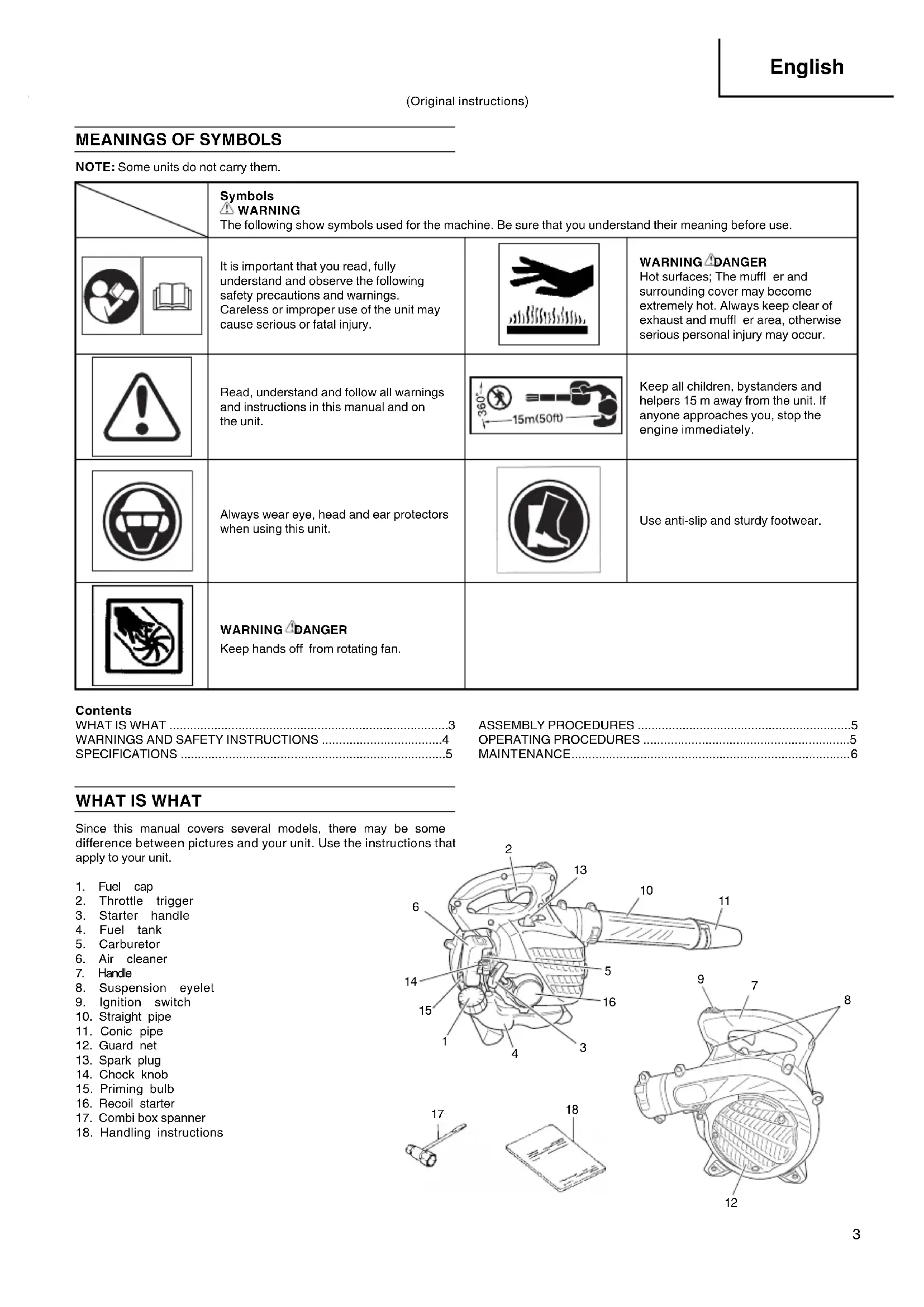
WHAT IS WHAT
Since this manual covers several models, there may be some difference between pictures and your unit. Use the instructions that apply to your unit.
- Fuel cap
- Throttle trigger
- Starter handle
- Fuel tank
- Carburetor
- Air cleaner
- Handle
- Suspension eyelet
- Ignition switch
- Straight pipe
- Conic pipe
- Guard net
- Spark plug
- Chock knob
- Priming bulb
- Recoil starter
- Combi box spanner
- Handling instructions

text_image
2 13 10 11 6 5 14 16 15 3 4 9 7 8 17 18 12 12 13WARNINGS AND SAFETY INSTRUCTIONS
Operator safety
○ A dust filter mask should be worn during operation.
○ Always wear a safety face shield or goggles.
○ Always wear heavy, long pants, boots and gloves. Do not wear loose clothing, jewelry, short pants, sandals or go barefoot. Secure hair so it is above shoulder length.
Do not operate this tool when you are tired, ill or under the influence of alcohol, drugs or medication.
○ Never let a child or inexperienced person operate the machine.
○ Wear hearing protection. Pay attention to your surroundings. Be aware of any bystanders who may be signaling a problem. Remove safety equipment immediately upon shutting off engine.
○ Wear head protection.
Never start or run the engine inside a closed room or building. Breathing exhaust fumes can kill.
○ Keep handles free of oil and fuel.
○ Keep hands away from moving part or heated area.
○ Do not grab or hold the unit by the blow pipe.
When the unit is turned off make sure the engine has stopped before the unit is set down.
When operation is prolonged, take a break from time to time so that you may avoid possible Hand-Arm Vibration Syndrome (HAVS) which is caused by vibration.
WARNING
○ Antivibration systems do not guarantee that you will not sustain Hand-Arm Vibration Syndrome or carpal tunnel syndrome. Therefore, continual and regular users should monitor closely the condition of their hands and fingers. If any symptoms of the above appear, seek medical advice immediately.
☐ If you are using any medical electric/electronic devices such as a pacemaker, consult your physician as well as the device manufacturer prior to operating any power equipment.
Unit/machine safety
○ Inspect the entire unit/machine before each use. Replace damaged parts. Check for fuel leaks and make sure all fasteners are in place and securely tightened.
○ Replace parts that are cracked, chipped or damaged in any way before using the unit/machine.
○ Make sure the safety guard is properly attached.
○ Keep others away when making carburetor adjustments.
○ Use only accessories as recommended for this unit/machine by the manufacturer.
WARNING
Never modify the unit/machine in any way. Do not use your unit/machine for any job except that for which it is intended.
Fuel safety
☐ Fuel contains highly flammable and it is possible to get the serious personal injury when inhaling or spilling on your body. Always pay attention when handling fuel. Always have good ventilation when handling fuel inside building.
○ Mix and pour fuel outdoors and where there are no sparks or flames.
○ Use a container approved for fuel.
☐ Do not smoke or allow smoking near fuel or the unit/machine or while using the unit/machine.
○ Wipe up all fuel spills before starting engine.
○ Move at least 3 m away from fueling site before starting engine.
○ Stop engine before removing fuel cap.
○ Empty the fuel tank before storing the unit/machine. It is recommended that the fuel be emptied after each use. If fuel is left in the tank, store so fuel will not leak.
Store unit/machine and fuel in area where fuel vapors cannot reach sparks or open flames from water heaters, electric motors or switches, furnaces. etc.
WARNING
Fuel is easy to ignite or get explosion or inhale fumes, so that pay special attention when handling or filling fuel.
Blowing safety
○ Operate unit/machine only at reasonable hours – not early in the morning or late at night when people might be disturbed. Comply with times listed in local ordinances. Usual recommendations are 9:00 a.m. to 5:00 p.m., Monday through Saturday.
Never direct discharge of air toward bystanders nor allow anyone near the area of operation. Use care in directing discharge to avoid glass enclosures, automobiles, etc.
○ Stay alert for uneven sidewalks, holes in terrain or other unstable condition when using the tool.
☐ Take all possible precautions when leaving the tool unattended such as stopping the engine.
☐ Never operate the tool without guards, blow pipes or other protective device in place. (If so equipped.)
Keep others including children, animals, bystanders and helpers outside the 15 m hazard zone. Stop the engine immediately if you are approached.
○ Always keep the engine on the right side of your body.
Keep firm footing and balance. Do not over-reach.
Keep all parts of your body away from the muffler.
○ Always carry a first-aid kit when operating any power equipment.
Never start or run the engine inside a closed room or building and/or near inflammable liquids. Breathing exhaust fumes can kill.
Maintenance safety
○ Maintain the unit/machine according to recommended procedures.
○ Disconnect the spark plug before performing maintenance except for carburetor adjustments.
○ Keep others away when making carburetor adjustments.
○ Use only genuine Hitachi replacement parts as recommended by the manufacturer.
CAUTION
Do not disassemble the recoil starter. You may get a possibility of personal injury with recoil spring.
Transport and storage
○ Carry the unit/machine by hand with the engine stopped and the muffler away from your body.
○ Allow the engine to cool, empty the fuel tank, and secure the unit/machine before storing or transporting in a vehicle.
Empty the fuel tank before storing the unit/machine. It is recommended that the fuel be emptied after each use. If fuel is left in the tank, store so fuel will not leak.
○ Store unit/machine out of the reach of children.
○ Clean and maintain the unit carefully and store it in a dry place.
○ Make sure engine switch is off when transporting or storing.
If situations occur which are not covered in this manual, take care and use common sense. Contact your Hitachi dealer if you need assistance. Pay special attention to statements preceded by the following words:

WARNING
Indicates a strong possibility of severe personal injury or loss of life, if instructions are not followed.
CAUTION
Indicates a possibility of personal injury or equipment damage, if instructions are not followed.
NOTE
Helpful information for correct function and use.
SPECIFICATIONS
| MODEL | RB24EAP/RB24EA |
| Engine Size (ml) 23.9 | |
| Spark Plug NGK BMR7A | |
| Dry weight (kg) 3.9 | |
| Fuel tank capacity (l) 0.52 | |
| Sound pressure levelLpA (dB (A))by ISO22868Uncertainty (dB (A)) | By ANSI 69^*2 By CEN 87^*1 1.8^*1 |
| Sound power levelLw measured (dB (A))by ISO22868Sound power level LwA (dB (A))by 2000/14/EC | 107^4 109^4 |
| Vibration level ( m/s^2 )by ISO22867Uncertainty ( m/s^2 ) | 121.0 |
*1: Equivalent noise level/vibration level are calculated as the time-weighted energy total for noise/vibration levels under various working conditions with the following time distribution: 1/7 Idle, 6/7 racing.
*2: ANSI B175.2
* All data subject to change without notice.
ASSEMBLY PROCEDURES
Blow pipes to main body (Fig. 1)
Inspect the main body and accessories.
Connect straight pipe (1) securely. Align projection (2) in straight pipe with groove (3) on blower housing and slide the pipe into the blower housing.
Rotate the pipe clockwise to lock it into place.
Conic pipe to straight pipe (Fig. 2)
○ Align groove (5) on the conic pipe (6) and projection (4) on straight pipe (1) and rotate the conic pipe in place.
OPERATING PROCEDURES
Fuel (Fig. 3)
WARNING
☐ The unit/machine is equipped with a two-stroke engine. Always run the engine on fuel, which is mixed with oil.
Provide good ventilation, when fueling or handling fuel.
☐ Fuel contains highly flammable and it is possible to get the serious personal injury when inhaling or spilling on your body. Always pay attention when handling fuel. Always have good ventilation when handling fuel inside building.
Fuel
○ Always use branded 89 octane unleaded gasoline.
Use genuine two-cycle oil or use a mix between 25:1 to 50:1, please consult the oil bottle for the ratio or Hitachi dealer.
☐ If genuine oil is not available, use an anti-oxidant added quality oil expressly labeled for air-cooled 2-cycle engine use (JASO FC GRADE OIL or ISO EGC GRADE). Do not use BIA or TCW (2-stroke water-cooling type) mixed oil.
○ Never use for four-stroke engine oil or waste oil.
○ Always mix fuel and oil in a separate clean container.
Always start by filing half the amount of fuel, which is to be used. Then add the whole amount of oil. Mix (shake) the fuel mixture. Add the remaining amount of fuel.
Mix (shake) the fuel-mix thoroughly before filling the fuel tank.
Fueling
WARNING
○ Always shut off the engine and let it cool for a few minutes before refueling.
○ Slowly open the fuel tank, when filling up with fuel, so that possible over-pressure disappears.
○ Tighten the fuel cap carefully, after fueling.
○ Always move the unit at least 3 m from the fueling area before starting.
Do not smoke and/or allow flames or sparks near fuel when handling or filling fuel.
○ Always wash any spilled fuel from clothing immediately with soap.
○ Be sure to check for any fuel leakage after refueling.
Before fueling, clean the tank cap area carefully, to ensure that no dirt falls into the tank. Make sure that the fuel is well mixed by shaking the container, before fueling.
Starting
CAUTION
Do not start if the pipe and guard net is obstructed.
- Check the switch (7) to ON position. (Fig. 4)
* Push priming bulb (8) about ten times so that fuel flows into carburetor. (Fig. 5) - Set choke lever to CLOSED position. (Fig. 6)
- Pull recoil starter briskly, taking care to keep the handle in your grasp and not allowing it to snap back. (Fig. 7)
- When you hear the engine want to start, return choke lever to RUN position (open). Then pull recoil starter briskly again.
WARNING
Never start or run the engine inside a closed room or building and/or near the inflammable liquid. Breathing exhaust fumes can kill.
○ Do not allow the rope to snap back in and always hold the unit firmly.
NOTE
If engine does not start, repeat procedures from 2 to 4.
- After starting engine, allow the engine about 2–3 minutes to warm up before subjecting it to any load.
* If the engine stops and is hard to restart straightaway, allow it to cool before trying again.
Operating blower (Fig. 8)
○ A low speed should be used to blow leaves and dry grass.
○ A medium speed should be used to clean wet leaves and grass.
○ A high speed should be used when moving gravel, dirt or other heavy materials.
WARNING
○ Do not direct discharge of air toward people or pet.
○ The unit should be operated in a well ventilated area.
☐ Never perform assembly or disassembly procedures with engine running or serious personal injury may result.
Never touch muffler, spark plug, or other metallic parts while engine is in running or immediately after shutting off engine.
CAUTION
This blower has been designed and adjusted to be used with all blowing pipes attached. It must never be operated without the straight pipe, and conic pipe.
Stopping (Fig. 9)
Decrease engine speed and run at an idle for a few minutes, then turn off ignition switch.
MAINTENANCE
MAINTENANCE, REPLACEMENT OR REPAIR OF THE EMISSION CONTROL DEVICES AND SYSTEMS MAY BE PERFORMED BY ANY NON-ROAD ENGINE REPAIR ESTABLISHMENT OR INDIVIDUAL.
Carburetor adjustment (Fig. 10)
In the carburetor, fuel is mixed with air. When the engine is test run at the factory, the carburetor is basically adjusted. A further adjustment may be required, according to climate and altitude. The carburetor has one adjustment possibility:
T = Idle speed adjustment screw.
Idle speed adjustment (T)
Check that the air filter is clean. If adjustment is required, turn IDLE speed Adjustment Screw (T) close (clockwise) to increase engine speed, open (counterclockwise) to decrease engine speed. Standard Idle rpm is 2800-3200rpm.
RECOMMENDATION
CARBURETOR ADJUSTMENT NEEDS THE SKILL OF EXPERIENCED OR WELL TRAINED PEOPLE, OR IS RECOMMENDED TO TAKE THE UNIT TO HITACHI DEALER.
Air fi Iter (Fig. 11)
The air filter must be cleaned from dust and dirt in order to avoid:
○ Carburetor malfunctions
○ Starting problems
○ Engine power reduction
○ Unnecessary wear on the engine parts
○ Abnormal fuel consumption
Remove the air cleaner cover by pushing and pulling back the tab on the top.
Clean the air filter daily or more often if working in exceptionally dusty areas.
Cleaning the air fi Iter
Open the air filter cover and the filter. Rinse it in warm soap suds. Check that the filter is dry before reassembly. An air filter that has been used for some time cannot be cleaned completely. Therefore, it must regularly be replaced with a new one. A damaged filter must always be replaced.
Fuel fi Iter (Fig. 12)
Drain all fuel from fuel tank and pull fuel filter line from tank. Pull filter element out of holder assembly and rinse element in warm water with detergent.
Rinse thoroughly until all traces of detergent are eliminated. Squeeze, do not wring, away excess water and allow element to air dry.
NOTE
If element is hard due to excessive dirt buildup, replace it.
Spark plug (Fig. 13)
The spark plug condition is influenced by:
○ An incorrect carburetor setting
○ Wrong fuel mixture (too much oil in the gasoline)
○ A dirty air fi lter
○ Hard running conditions (such as cold weather)
These factors cause deposits on the spark plug electrodes, which may result in malfunction and starting difficulties. If the engine is low on power, difficult to start or runs poorly at idling speed, always check the spark plug first. If the spark plug is dirty, clean it and check the electrode gap. Re-adjust if necessary. The correct gap is 0.6 mm. The spark plug should be replaced after about 100 operation hours or earlier if the electrodes are badly eroded.
NOTE
In some areas, local law requires using a resistor spark plug to suppress ignition signals. If this machine was originally equipped with resistor spark plug, use same type of spark plug for replacement.
Maintenance schedule
Below you will find some general maintenance instructions. For further information please contact your Hitachi dealer.
Daily maintenance
○ Clean the exterior of the unit.
○ Check the dust cover for damage or cracks. Change the cover in case of impacts or cracks.
○ Check that nuts and screws are sufficiently tightened.
Weekly maintenance
○ Check the starter, especially the cord.
○ Clean the exterior of the spark plug.
○ Remove the spark plug and check the electrode gap. Adjust it to 0.6 mm, or change the spark plug.
○ Clean the air filter.
Monthly maintenance
○ Rinse the fuel tank with gasoline, and clean fuel filter.
○ Clean the exterior of the carburetor and the space around it.
Quarterly maintenance
○ Clean the cooling fins on the cylinder.
○ Clean the fan and the space around it.
○ Clean the muffler of carbon.
CAUTION
Cleaning of cylinder fins, fan and muffler shall be done by a Hitachi Authorized Service Center.
NOTE
When ordering the parts to your nearest dealer, please use the item No. showing on the parts breakdown section in this instruction.
SYMBOLBEDEUTUNGEN
WAARSCHUWINGEN EN VEILIGHEIDSINSTRUCTIES ....23
SPECIFICATIONS....24
MONTAGEPROCEDURES....24
BEDIENING 24
ONDERHOUD 25
WAT IS WAT
WAARSCHUWINGEN EN VEILIGHEIDSINSTRUCTIES
text_image
Exploded view diagram of a motorcycle body assembly with numbered parts and exploded views
natural_image
Line drawing of a quill pen in an inkwell (no text or symbols)
natural_image
Line drawing of a quill pen with inkwell (no text or symbols)| English EC | DECLARATION OF CONFORMITY Nederlands EC VER(Applies to Europe only)We declare under our sole responsibility that this product is in conformity with Directive 2006/42/EC, 2014/30/EU and 2000/14/EC.The following standards have been taken into consideration.ISO 3864, EN ISO 12100-1/2EN15503: 2009Annex V (2000/14/EC): For information relating to noise emissions, see the chapter specifi cations.The European Standards Manager at the representative office in Europe is authorized to compile the technical fi le.This declaration is applicable to the product affixed CE marking. | KLARING VAN CONFORMITEIT(Geldt alleen voor Europa)Wij verklaren onder eigen verantwoordelijkheid dat dit product voldoet aan de richtlijn 2006/42/EC, 2014/30/EU en 2000/14/EC.De volgende standaards zijn toegepast.ISO 3864, EN ISO 12100-1/2EN15503: 2009Aanvulling V (2000/14/EC): Voor informatie over de lawaai-emissie wordt u verwezen naar het hoofdstuk met de specifi caties.De Europese Normen Manager bij de vertegenwoordiging in Europa is gemachtigd om het technisch dossier samen te stellen.Deze verklaring is van toepassing op produkten voorzien van de CEmarkeringen. |
| Deutsch | EG-KONFORMITÄTSERKLÄRUNG Español DE(Gilt nur für Europa)Wir erklären unter unserer Alleinverantwortung, dass dieses Produkt konform zu den Richtlinien 2006/42/EG, 2014/30/EU und 2000/14/EG ist.Die nachfolgenden Standards wurden in Betracht gezogen.ISO 3864, EN ISO 12100-1/2EN15503: 2009Anhang V (2000/14/EG): Informationen zur Geräuschentwicklung finden Sie im Kapitel Spezifizierungen.Die Leitung der repräsentativen Behörde für europäische Normen und Richtlinien ist berechtigt, die technischen Unterlagen zusammenzustellen.Diese Erklärung gilt für Produkte, die die CE-Markierung tragen. | DECLARACIÓN DE CONFORMIDAD DE LA CE(De aplicación sólo en Europa)Declaramos bajo nuestra responsabilidad que este producto se ajusta a la Directiva 2006/42/CE, 2014/30/UE y 2000/14/CE.Se han tenido en consideración las siguientes normas.ISO 3864, EN ISO 12100-1/2EN15503: 2009Anexo V (2000/14/CE): Para más información sobre la emisión de ruidos, consulte la sección de especificaciones.El Director de Normas Europeas en la oficina de representación en Europa está autorizado para elaborar el expediente técnico.Esta declaración se aplica a los productos con marcas de la CE. |
| Français | DECLARATION DE CONFORMITE CE Português (Concerne l'Europe uniquement)Nous déclarons sous notre unique responsabilité que ce produit est conforme aux Directives 2006/42/CE, 2014/30/UE et 2000/14/CE.Les normes suivantes ont été prises en considération.ISO 3864, EN ISO 12100-1/2EN15503: 2009Annexe V (2000/14/CE): Pour les informations relatives aux émissions de bruits, reportez-vous au chapitre Caractéristiques.Le Gestionnaire des normes européennes du bureau de représentation en Europe est autorisé à constituer le dossier technique.Cette déclaration s'applique aux produits désignés CE. | DECLARAÇÃO DE CONFORMIDADE CE(Aplica-se apenas à Europa)Declaramos sob nossa única responsabilidade que este produto está em conformidade com a Directiva 2006/42/CE, 2014/30/UE e 2000/14/CE.As seguintes normas harmonizadas foram aplicadas.ISO 3864, EN ISO 12100-1/2EN15503: 2009Anexo V (2000/14/CE): Para obter mais informações relacionadas com emissões de ruído, consulte as especificações do capítulo.O Gestor de Normas Europeias no escritório de representação na Europa está autorizado a compilar o fi cheiro técnico.Esta declaração se aplica aos produtos designados CE. |
| Italiano | DICHIARAZIONE DI CONFORMITÀ CE(Si applica solo all'Europa)Dichiariamo sotto la nostra sola responsabilità che questo prodotto è conforme alla Direttiva 2006/42/CE, 2014/30/UE e 2000/14/CE.Sono stati presi in considerazione i seguenti standard.ISO 3864, EN ISO 12100-1/2EN15503: 2009Allegato V (2000/14/CE): Per informazioni riguardo alle emissioni di rumore, consultare le specifi che del capitolo.Il gestore delle norme europee presso l'ufficio di rappresentanza in Europa è autorizzato a compilare il fascicolo tecnico.Questa dichiarazione è applicabile ai prodotti cui sono applicati i marchi CE. | |
| Representative offi ce in EuropeHitachi Power Tools Europe GmbHSiemensring 34, 47877 Willich, GermanyHead offi ce in JapanHitachi Koki Co., Ltd.Shinagawa Intercity Tower A, 15-1, Konan 2-chome,Minato-ku, Tokyo, Japan | CE 31.3.2017Naoto YamashiroEuropean Standard Manager31.3.2017M. HaradaExecutive Offi cer | |