
NR1890DR - Stapler HITACHI - Free user manual and instructions
Find the device manual for free NR1890DR HITACHI in PDF.
| Product Type | Cordless Strip Nailer (Stapler) |
| Brand | Hitachi |
| Model | NR1890DR |
| Dimensions (L × H × W) | 342 mm × 342 mm × 137 mm |
| Weight (with battery) | Approximately 4.6 kg (BSL1830C) / 4.9 kg (BSL1860) |
| Power Source | 18 V lithium-ion battery (BSL1830C or BSL1860) |
| Battery Voltage | 18 V DC |
| Nail Length Range | 50 mm to 90 mm (2 in to 3-1/2 in) |
| Magazine Capacity | 37 nails (plastic strip) |
| Trigger Mode | Full sequential or contact (selectable) |
| Nailing Frequency | 1.5 to 2 nails per second (intermittent) |
| Main Features | Intermittent and continuous nailing, depth adjustment, auto shut-off (30 min), battery indicator, USB port |
| Operating Temperature | 0°C to 40°C (32°F to 104°F) |
| Maintenance and Cleaning | Clean the magazine and push lever regularly with compressed air |
| Safety | Trigger lock, safety push lever, safety glasses required |
| Spare Parts | Use only genuine Hitachi parts |
| Repairability | Contact authorized Hitachi service center |
| Included Accessories | Safety glasses, battery (depending on kit), charger, bag, battery cover, Allen keys |
| Applications | Framing, truss construction, decking, formwork, caravans |
Frequently Asked Questions - NR1890DR HITACHI
User questions about NR1890DR HITACHI
0 question about this device. Answer the ones you know or ask your own.
Ask a new question about this device
Download the instructions for your Stapler in PDF format for free! Find your manual NR1890DR - HITACHI and take your electronic device back in hand. On this page are published all the documents necessary for the use of your device. NR1890DR by HITACHI.
USER MANUAL NR1890DR HITACHI
Cordless Strip Nailer
natural_image
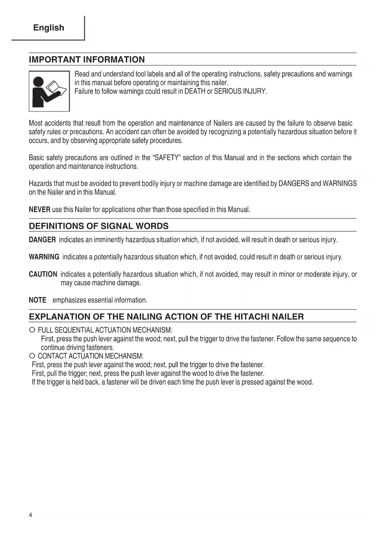
Technical line drawing of a mechanical assembly (no text or symbols)NR1890DC
natural_image
Technical line drawing of a mechanical assembly (no text or symbols)NR1890DR
DANGER
Improper use of this Nailer can result in death or serious injury!
This Manual contains important information about product safety.
Read and understand this Manual before operating the Nailer.
Never allow anyone who has not reviewed this manual to use the tool.
This manual should be stored in safe place.
DANGER
IMPORTANT INFORMATION ....4
DEFINITIONS OF SIGNAL WORDS 4
REMOVAL AND INSTALLATION METHOD OF BATTERY....18
CHARGING METHOD 18
HOW TO RECHARGE USB DEVICE ....21
BEFORE OPERATION ....22 PREPARING THE BATTERY ....22
ADJUSTING THE NAILING DEPTH 29
USING THE HOOK 29
CLEARING A JAM 30
MAINTENANCE
MAINTENANCE AND INSPECTION 31
SERVICE AND REPAIRS 32
PARTS LIST 100
TABLE DES MATIÈRES
Français
Page Page
INFORMATION IMPORTANTE ....34
DEFINITION DES MOTS DE SIGNALISATION .....34
EXPLICATION DE L'ACTION DE CLOUAGE DU CLOUEUR HITACHI ....34
SECURITE
AVERTISSEMENTS DE SÉCURITÉ GÉNÉRAUX CONCERNANT LES OUTILS ÉLECTRIQUES .....35
CONSIGNES DE SÉCURITÉ POUR CLOUEUR .....37
CONSIGNES DE SECURITE IMPORTANTES POUR L'UTILISATION DU CLOUEUR ....38
CONSIGNES DE SÉCURITÉ IMPORTANTES POUR LE CHARGEUR DE BATTERIE ....40
CONSIGNES DE SÉCURITÉ IMPORTANTES POUR L'UTILISATION DE LA BATTERIE ET DU CHARGEUR DE BATTERIE ....41
PRÉCAUTIONS RELATIVES A LA BATTERIE AU LITHIUM ION 42
À PROPOS DU TRANSPORT DE LA BATTERIE LITHIUM-ION....43
PRÉCAUTIONS LORS DE LA CONNEXION DU DISPOSITIF USB 43
RESPONSABILITES DE L'EMPLOYEUR ....43
UTILISATION
NOM DES PIÈCES 45
SPECIFICATIONS 46
SELECTION DES CLOUS ....47
ACCESSORIES....49
ACCESSOIRES STANDARD 49
ACCESSOIRES EN OPTION 50
APPLICATIONS 50
MÉTHODE DE RETRAIT ET D'INSTALLATION DE LA BATTERIE ....50
MÉTHODE DE RECHARGE ....50
CHARGEMENT DU DISPOSITIF USB ....53
AVANT L'UTILISATION....54 PRÉPARATION DE LA PILE....54 COMMENT UTILISER LE PANNEAU DE COMMANDE....54
ESSAI DU CLOUEUR ....55
CHARGEMENT DES CLOUS ....58
UTILISATION DU CLOUEUR ....59
MÉTHODES D'UTILISATION 60
RÉGLAGE DE LA PROFONDEUR DE CLOUAGE 61
UTILISATION DU CROCHET 62
ÉLIMINATION D'UN BLOCAGE ....62
ENTRETIEN
ENTRETIEN ET INSPECTION 63
ENTRETIEN ET REPARATIONS ....64
LISTE DES PIECES ....100
ÍNDICE
Español
Página Página
Read and understand tool labels and all of the operating instructions, safety precautions and warnings in this manual before operating or maintaining this nailer.
Failure to follow warnings could result in DEATH or SERIOUS INJURY.
Most accidents that result from the operation and maintenance of Nailers are caused by the failure to observe basic safety rules or precautions. An accident can often be avoided by recognizing a potentially hazardous situation before it occurs, and by observing appropriate safety procedures.
Basic safety precautions are outlined in the “SAFETY” section of this Manual and in the sections which contain the operation and maintenance instructions.
Hazards that must be avoided to prevent bodily injury or machine damage are identified by DANGERS and WARNINGS on the Nailer and in this Manual.
NEVER use this Nailer for applications other than those specified in this Manual.
DEFINITIONS OF SIGNAL WORDS
DANGER indicates an imminently hazardous situation which, if not avoided, will result in death or serious injury.
WARNING indicates a potentially hazardous situation which, if not avoided, could result in death or serious injury.
CAUTION indicates a potentially hazardous situation which, if not avoided, may result in minor or moderate injury, or may cause machine damage.
NOTE emphasizes essential information.
○ FULL SEQUENTIAL ACTUATION MECHANISM:
First, press the push lever against the wood; next, pull the trigger to drive the fastener. Follow the same sequence to continue driving fasteners.
O CONTACT ACTUATION MECHANISM:
First, press the push lever against the wood; next, pull the trigger to drive the fastener.
First, pull the trigger; next, press the push lever against the wood to drive the fastener.
If the trigger is held back, a fastener will be driven each time the push lever is pressed against the wood.
SAFETY
GENERAL POWER TOOL SAFETY WARNINGS
WARNING
Read all safety warnings and all instructions.
Failure to follow the warnings and instructions may result in electric shock, fire and/or serious injury.
Save all warnings and instructions for future reference.
The term “power tool” in the warnings refers to your mains-operated (corded) power to (cordless) power tool.
1) Work area safety
a) Keep work area clean and well lit. Cluttered or dark areas invite accidents
b) Do not operate power tools in explosive atmospheres, such as in the presence of fl ammable liquids, gases or dust. Power tools create sparks which may ignite the dust or fumes.
c) Keep children and bystanders away while operating a power tool. Distractions can cause you to lose control.
2) Electrical safety
a) Power tool plugs must match the outlet. Never modify the plug in any way. Do not use any adapter plugs with earthed (grounded) power tools. Unmodified plugs and matching outlets will reduce risk of electric shock.
b) Avoid body contact with earthed or grounded surfaces such as pipes, radiators, ranges and refrigerators. There is an increased risk of electric shock if your body is earthed or grounded.
c) Do not expose power tools to rain or wet conditions. Water entering a power tool will increase the risk of electric shock.
d) Do not abuse the cord. Never use the cord for carrying, pulling or unplugging the power tool. Keep cord away from heat, oil, sharp edges or moving parts. Damaged or entangled cords increase the risk of electric shock.
e) When operating a power tool outdoors, use an extension cord suitable for outdoor use. Use of a cord suitable for outdoor use reduces the risk of electric shock.
f) If operating a power tool in a damp location is unavoidable, use a residual current device (RCD) protected supply.
Use of an RCD reduces the risk of electric shock.
3) Personal safety
a) Stay alert, watch what you are doing and use common sense when operating a power tool. Do not use a power tool while you are tired or under the influence of drugs, alcohol or medication.
A moment of inattention while operating power tools may result in serious personal injury.
b) Use personal protective equipment. Always wear eye protection.
Protective equipment such as dust m skid safety shoes, hard hat, or hearing protection used for appropriate conditions will reduce personal injuries.
c) Prevent unintentional starting. Ensure the switch is in the off-position before connecting to power source and/or battery pack, picking up or carrying the tool.
Carrying power tools with your finger on the switch or energising power tools that have the switch on invites accidents.
d) Remove any adjusting key or wrench before turning the power tool on.
A wrench or a key left attached to a rotating part of the power tool may result in personal injury.
e) Do not overreach. Keep proper footing and balance at all times.
This enables better control of the power tool in unexpected situations.
f) Dress properly. Do not wear loose clothing or jewellery. Keep your hair, clothing and gloves away from moving parts.
Loose clothes, jewellery or long hair can be caught in moving parts.
g) If devices are provided for the connection of dust extraction and collection facilities, ensure these are connected and properly used.
Use of dust collection can reduce dust-related hazards.
SAFETY — Continued
4) Power tool use and care
a) Do not force the power tool. Use the correct power tool for your application.
The correct power tool will do the job better and safer at the rate for which it was designed.
b) Do not use the power tool if the switch does not turn it on and off.
Any power tool that cannot be controlled with the switch is dangerous and must be repaired.
c) Disconnect the plug from the power source and/or the battery pack from the power tool before making any adjustments, changing accessories, or storing power tools.
Such preventive safety measures reduce the risk of starting the power tool accidentally.
d) Store idle power tools out of the reach of children and do not allow persons unfamiliar with the power tool or these instructions to operate the power tool.
Power tools are dangerous in the hands of untrained users.
e) Maintain power tools. Check for misalignment or binding of moving parts, breakage of parts and any other condition that may affect the power tool's operation.
If damaged, have the power tool repaired before use.
Many accidents are caused by poorly maintained power tools.
f) Keep cutting tools sharp and clean.
Properly maintained cutting tools with sharp cutting edges are less likely to bind and are easier to control.
g) Use the power tool, accessories and tool bits etc. in accordance with these instructions, taking into account the working conditions and the work to be performed.
Use of the power tool for operations different from those intended could result in a hazardous situation.
5) Battery tool use and care
a) Recharge only with the charger specified by the manufacturer.
A charger that is suitable for one type of battery pack may create a risk of fire when used with another battery pack.
b) Use power tools only with specifically designated battery packs.
Use of any other battery packs may create a risk of injury and fire.
c) When battery pack is not in use, keep it away from other metal objects like paper clips, coins, keys, nails, screws, or other small metal objects, that can make a connection from one terminal to another.
Shorting the battery terminals together may cause burns or a fire.
d) Under abusive conditions, liquid may be ejected from the battery; avoid contact. If contact accidentally occurs, flush with water. If liquid contacts eyes, additionally seek medical help.
Liquid ejected from the battery may cause irritation or burns.
6) Service
a) Have your power tool serviced by a qualified repair person using only identical replacement parts.
This will ensure that the safety of the power tool is maintained.
- WARNING -
To reduce the risk of injury, user must read instruction manual.
WARNING:
Some dust created by power sanding, sawing, grinding, drilling, and other construction activities contains chemicals known to the State of California to cause cancer, birth defects or other reproductive harm. Some examples of these chemicals are:
● Lead from lead-based paints,
● Crystalline silica from bricks and cement and other masonry products, and
● Arsenic and chromium from chemically-treated lumber.
Your risk from these exposures varies, depending on how often you do this type of work. To reduce your exposure to these chemicals: work in a well ventilated area, and work with approved safety equipment, such as those dust masks that are specially designed to filter out microscopic particles.
SAFETY — Continued
NAILER SAFETY WARNINGS
WARNING
- Always assume that the tool contains fasteners.
Careless handling of the nailer can result in unexpected fi ring of fasteners and personal injury. - Do not point the tool towards yourself or anyone
nearby. Unexpected triggering will-fastener causing an injury. -
Do not actuate the tool unless the tool is placed
fi rmly against the workpiece. If the tool is not in contact with the workpiece, the fastener may be deflected away from your target. -
Disconnect the tool from the power source when the fastener jams in the tool. While removing a jammed fastener, the nailer may be accidentally activated if it is plugged in.
Use cautionwhile removing a jammed fastener.
The mechanism may be under compression and the fastener may be forcefully discharged while attempting to free a jammed condition. - Do not use this nailer for fastening electric cables.
It is not designed for electric cable installation and may damage the insulation of electric cables thereby causing electric shock or fire hazards.
IMPORTANT SAFETY INSTRUCTIONS FOR USING NAILERS
READ ALL INSTRUCTIONS
DANGER
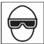
1. OPERATORS AND OTHERS IN WORK AREA MUST WEAR SAFETY GLASSES WITH SIDE SHIELDS.
When operating the Nailer, always wear safety glasses with side shields, and make sure others in work area wear safety glasses, too.
Safety glasses must conform to the requirements of American National Standards Institute, ANSI Z87.1 and provide protection against flying particles both from the front and side.
The employer must enforce the use of safety glasses by the Nailer operator and others in work area.
WARNING
2. NEVER POINT TOOL AT YOURSELF OR OTHERS IN WORK AREA.
Always assume the Nailer contains fasteners.
Never point the Nailer at yourself toward yourself or others, whether it contains fasteners or not.
If fasteners are mistakenly driven, it can lead to severe injuries.
Never engage in horseplay with the Nailer.
Respect the Nailer as a working implement.
3. KEEP FINGERS AWAY FROM TRIGGER WHEN NOT DRIVING FASTENERS TO AVOID ACCIDENTAL FIRING.
Never carry the Nailer with finger on trigger since you could drive a fastener unintentionally and injure yourself or someone else.
Always carry the Nailer by the handle only.
4. CHOICE OF TRIGGERING METHOD IS IMPORTANT.
Read and understand section titled "Methods of operation." (pages 27 - 29)
SAFETY — Continued
5. ALWAYS WEAR EAR AND HEAD PROTECTION.
Always wear ear protection to protect your ears from loud noise.
Always wear head protection to protect from flying objects.
6. OPERATE WITHIN PROPER TEMPERATURE RANGE.
The operating environment for this device is between 32^ F ( 0^ C) and 104^ F ( 40^ C) so ensure use within this temperature range.
The device may fail to operate below 32^ F ( 0^ C) or above 104^ F ( 40^ C).
7. STORE NAILER PROPERLY, AND BATTERY REMOVED.
When not in use, the Nailer, battery and battery charger should be stored in a dry place. Keep out of reach of children. Lock the storage area.
8. KEEP WORK AREA CLEAN.
Cluttered areas invite injuries. Clear all work areas of unnecessary tools, debris, furniture, etc.
9. KEEP VISITORS AWAY.
Do not let visitors handle the Nailer.
All visitors should be kept safely away area. In
10. DRESS PROPERLY.
Do not wear loose clothing or jewelry as they can be caught in moving parts.
Rubber gloves and nonskid footwear are recommended when working outdoors.
Wear protective hair covering to contain long hair.
11. CHECK PUSH LEVER BEFORE USE.
Make sure the push lever operates properly. (The push lever may be called “Safety”.) Never use the Nailer unless the push lever is operating properly, otherwise the Nailer could drive a fastener unexpectedly. Do not tamper with or remove the push lever, otherwise the push lever becomes inoperable.
12. KEEP ALL SCREWS AND COVERS TIGHTLY IN PLACE.
Keep all screws and covers tightly mounted. Check their condition periodically.
Never use the Nailer if parts are missing or damaged.
13. DO NOT LOAD FASTENERS WITH TRIGGER OR PUSH LEVER DEPRESSED.
When loading fasteners into the Nailer,
1) do not depress the trigger;
2) do not depress the push lever; and
3) keep the Nailer pointed downward.
14. KEEP FACE, HANDS AND FEET AWAY FROM FIRING HEAD DURING USE.
Never place your face, hands or feet closer than 8 inches(200 mm) from the fi ring head.
A serious injury can result if the fasteners are defl ected by the workpiece, or are driven away from the point of entry.
15. PLACE NAILER PROPERLY ON WORKPIECE.
Do not drive fasteners on top of other fasteners or with the Nailer at too steep of an angle; the fasteners can ricochet and hurt someone.
16. BEFORE STARTING WORK, CHECK THE FASTENING OPERATION SWITCHING DEVICE.
This Hitachi nailer includes a fastening operation switching device.
Before starting work, check the setting of the operation switching device.
If the switching device is not set properly, the nailer will not operate correctly.
17. BE CAREFUL OF DOUBLE FIRE DUE TO RECOIL.
If the push lever is unintentionally allowed to re-contact the workpiece following recoil, an unwanted fastenerwill be driven.
In order to avoid this undesirable double fire,
○ Intermittent operation (Trigger firing)
1) Set the switching device to FULL SEQUENTIAL ACTUATION MECHANISM.
2) Pull the trigger rapidly and firmly.
○ Continuous operation (Push lever firing)
1) Do not press the nailer against the wood with excessive force.
2) Separate the nailer from the wood as after fastening.
18. DO NOT DRIVE FASTENERS INTO THIN BOARDS OR NEAR CORNERS AND EDGES OF WORKPIECE.
The fasteners can be driven through or away from the workpiece and hit someone.
19. NEVER DRIVE FASTENERS FROM BOTH SIDES OF A WALL AT THE SAME TIME.
The fasteners can be driven into and through the wall and hit a person on the opposite side.
20. CHECK FOR LIVE WIRES.
Avoid the risk of severe electrical shock by checking for live electrical wires that may be hidden by walls, floors or ceilings. Turn off the breaker switch to ensure there are no live wires.
21. DO NOT OVERREACH.
Keep proper footing and balance at all times.
SAFETY — Continued
22. NEVER USE NAILER WHICH IS DEFECTIVE OR OPERATING ABNORMALLY.
If the Nailer appears to be operating unusually, making strange noises, or otherwise appears defective, stop using it immediately and arrange for repairs by a Hitachi authorized service center.
23. REMOVE ALL REMAINING FASTENERS AND BATTERY FROM NAILER WHEN:
1) doing maintenance and inspection;
2) checking proper operation of push lever and trigger;
3) clearing a jam;
4) it is not in use;
5) leaving work area;
6) moving it to another location; and
7) handing it to another person.
Never attempt to clear a jam or repair the Nailer unless you have removed battery and all remaining fasteners from the Nailer.
The Nailer should never be left unattended since people who are not familiar with the Nailer might handle it and injure the themselves.
24. REMOVE BATTERY FROM NAILER WHEN:
1) loading fasteners;
2) turning the adjuster.
25. STAY ALERT.
Watch what you are doing. Use common sense.
Do not operate the Nailer when you are tired.
The Nailer should never be used by you if you are under the influence of alcohol, drugs or medication that makes you drowsy.
26. HANDLE NAILER CORRECTLY.
Operate the Nailer according to this Manual.
Never allow the Nailer to be operated by children, individuals unfamiliar with its operation or unauthorized personnel.
27. NEVER USE NAILER FOR APPLICATIONS OTHER THAN THOSE SPECIFIED IN THIS MANUAL.
28. HANDLE NAILER CAREFULLY.
Do not drop the Nailer or strike the Nailer against hard surfaces; and do not scratch or engrave signs on the Nailer. Handle the Nailer carefully.
29. MAINTAIN NAILER WITH CARE.
Keep the Nailer clean and lubricated for better and safer performance.
30. USE ONLY PARTS, ACCESSORIES OR FASTENERS SUPPLIED OR RECOMMENDED BY HITACHI.
Unauthorized parts, accessories, or fasteners may void your warranty and can lead to malfunction and resulting injuries.
Only service personnel trained by Hitachi, distributor or employer shall repair the Nailer.
31. NEVER MODIFY OR ALTER A NAILER.
Doing so may cause it to malfunction and personal injuries may result.
32. NEVER allow magnets (or similar magnetic devices) to be adjacent to the nailer, because the nailer has a magnetic sensor inside.
Doing so will cause a failure or risk of injury by malfunction.
IMPORTANT SAFETY INSTRUCTIONS FOR BATTERY CHARGER
WARNING
Death or serious bodily injury could result from improper or unsafe use of battery chargers.
To avoid these risks, follow these basic safety instructions:
READ ALL INSTRUCTIONS
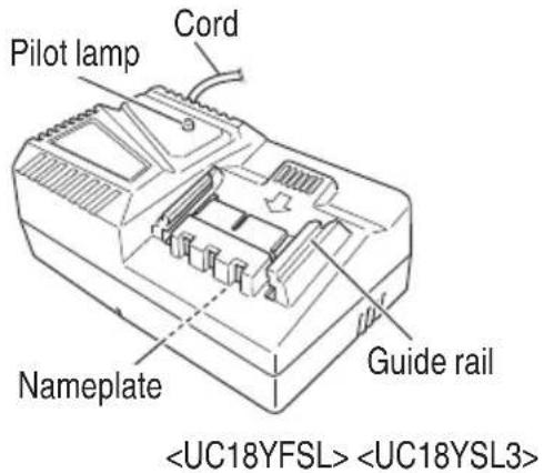
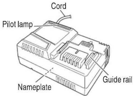
- This manual contains important safety and operating instructions for battery charger Model UC18YFSL/UC18YSL3.
- Before using battery charger, read all instructions and cautionary markings on (1) battery charger, (2) battery, and (3) product using battery.
- To reduce risk of injury, charge HITACHI rechargeable battery type BSL18 series. Other type of batteries may burst causing personal injury and damage.
- Do not expose battery charger to rain or snow.
- Use of an attachment not recommended or sold by the battery charger manufacturer may result in a risk of fire, electric shock, or injury to persons.
- To reduce risk of damage to electric plug and c pull by plug when disconnecting battery charger.
- Make sure cord is located so that it will not be stepped on, tripped over, or otherwise subjected to damage or stress.
- An extension cord should not be used unless absolutely necessary. Use of improper extension cord could result in a risk of fire and electric shock.
If extension cord must be used make sure:
a. That blades of extension cord are the same number, size, and shape as those of plug on battery charger;
SAFETY — Continued
b. That extension cord is properly wired and in good electrical condition; and
c. That wire size is large enough for AC ampere rating of battery charger as specified in Table 1.
Table 1
RECOMMENDED MINIMUM AWG SIZE FOR
EXTENSION CORDS FOR BATTERY CHARGERS
| AC Input Rating Amperes* AWG Size of Cord | ||
| Equal to or greater than | but less than | Length of Cord, Feet (Meter)25 (7.5) 50 (15) 100 (30) 150 (45) |
| 02 18 18 18 16 | ||
| 23 18 18 16 14 | ||
| 34 18 18 16 14 | ||
* If the input rating of a battery charger is given in watts rather than in amperes, the corresponding ampere rating is to be determined by dividing the wattage rating by the voltage rating—for example:
$$ \frac {1 , 2 5 0 \text { watts }}{1 2 5 \text { volts }} = 1 0 \text { amperes } $$
- Do not operate battery charger with damaged cord or plug-replace them immediately.
- Do not operate battery charger if it has received a sharp blow, been dropped, or otherwise damaged in any way; take it to a qualified serviceman.
- Do not disassemble battery charger; take it to a qualified serviceman when service or repair is required. Incorrect reassembly may result in a risk of electric shock or fire.
- To reduce risk of electric shock, unplug charger from receptacle before attempting any maintenance or cleaning. Removing the battery will not reduce this risk.
IMPORTANT SAFETY INSTRUCTIONS FOR USE OF THE BATTERY AND BATTERY CHARGER
You must charge the battery before you can use the power tool. Before using the model UC18YFSL/UC18YSL3 battery charger, be sure to read all instructions and cautionary statements on it, the battery and in this manual.
REMEMBER: USE ONLY HITACHI BATTERY TYPES BSL18 SERIES. OTHER TYPES OF BATTERIES MAY BURST AND CAUSE INJURY!
Follow these instructions to avoid the risk of injury:

WARNING
Improper use of the battery or battery charger can lead to serious injury. To avoid these injuries:
- NEVER disassemble the battery.
- NEVER incinerate the battery, even if it is damaged or is completely worn out. The battery can explode in a fire.
- NEVER short-circuit the battery.
- NEVER insert any objects into the battery charger's air vents. Electric shock or damage to the battery charger may result.
- NEVER charge outdoors. Keep the battery away from direct sunlight and use only where there is low humidity and good ventilation.
- NEVER charge when the temperature is below 32^ F ( 0^ C) or above 104^ F ( 40^ C).
- NEVER connect two battery chargers together.
- NEVER insert foreign objects into the hole for the battery or the battery charger.
- NEVER use a booster transformer when charging.
- NEVER use an engine generator or DC power to charge.
- NEVER store the battery or battery charger in places where the temperature may reach or exceed 104^ F ( 40^ C).
- ALWAYS operate charger on standard household electrical power (120 volts). Using the charger on any other voltage may overheat and damage the charger.
- ALWAYS wait at least 15 minutes between charges to avoid overheating the charger.
- ALWAYS disconnect the power cord from its receptacle when the charger is not in use.
SAFETY — Continued
CAUTION ON LITHIUM-ION BATTERY
To extend the lifetime, the lithium-ion battery equips with the protection function to stop the output.
In the cases of 1 to 3 described below, when using this product, even if you are pulling the switch, the motor may stop. This is not the trouble but the result of protection function.
- When the battery power remaining runs out, the motor stops.
In such case, charge it up immediately.
- If the tool is overloaded, the motor may stop. In this case, release the switch of tool and eliminate causes of overloading. After that, you can use it again.
- If the battery is overheated under overload work, the battery power may stop.
In this case, stop using the battery and let the battery cool. After that, you can use it again.
Furthermore, please heed the following warning and caution.

WARNING
In order to prevent any battery leakage, heat generation, smoke emission, explosion and ignition beforehand, please be sure to heed the following precautions.
- Make sure that swarf and dust do not collect on the battery.
During work make sure that swarf and dust do not fall on the battery.
○ Make sure that any swarf and dust falling on the power tool during work do not collect on the battery.
○ Do not store an unused battery in a location exposed to swarf and dust.
Before storing a battery, remove any swarf and dust that may adhere to it and do not store it together with metal parts (screws, nails, etc.). - Do not pierce battery with a sharp object such as a nail, strike with a hammer, step on, throw or subject the battery to severe physical shock.
- Do not use an apparently damaged or deformed battery.
- Do not use the battery in reverse polarity.
- Do not connect directly to an electrical outlets or car cigarette lighter sockets.
-
Do not use the battery for a purpose other than those specified.
-
If the battery charging fails to complete even when a specified recharging time has elapsed, immediately stop further recharging.
- Do not put or subject the battery to high temperatures or high pressure such as into a microwave oven, dryer, or high pressure container.
- Keep away from fi re immediately when leakage or foul odor are detected.
- Do not use in a location where strong static electricity generates.
- If there is battery leakage, foul odor, heat generated, discolored or deformed, or in any way appears abnormal during use, recharging or storage, immediately remove it from the equipment or battery charger, and stop use.

CAUTION
- If liquid leaking from the battery gets into your eyes, do not rub your eyes and wash them well with fresh clean water such as tap water and contact a doctor immediately.
If left untreated, the liquid may cause eye-problems.
- If liquid leaks onto your skin or clothes, wash well with clean water such as tap water immediately.
There is a possibility that this can cause skin irritation. - If you find rust, foul odor, overheating, discolor, deformation, and/or other irregularities when using the battery for the first time, do not use and return it to your supplier or vendor.

WARNING
If an electrically conductive foreign object enters the terminals of the lithium ion battery, a short-circuit may occur resulting in the risk of fire. Please observe the following matters when storing the battery.
Do not place electrically conductive cuttings, nails, steel wire, copper wire or other wire in the storage case.
○ Either install the battery in the power tool or store by securely pressing into the battery cover until the ventilation holes are concealed to prevent short-circuits.
SAFETY — Continued
REGARDING LITHIUM-ION BATTERY TRANSPORTATION
When transporting a lithium-ion battery, please observe the following precautions.

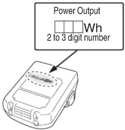
WARNING
Notify the transporting company that a package contains a lithium-ion battery, inform the company of its power output and follow the instructions of the transportation company when arranging transport.
● Lithium-ion batteries that exceed a power output of 100 Wh are considered to be in the freight classification of Dangerous Goods and will require special application procedures.
- For transportation abroad, you must comply with international law and the rules and regulations of the destination country.
USB DEVICE CONNECTION PRECAUTIONS
When an unexpected problem occurs, the data in a USB device connected to this product may be corrupted or lost. Always make sure to back up any data contained in USB device prior to use with this product.
Please be aware that our company accepts absolutely no responsibility for any data stored in a USB device that is corrupted or lost, nor for any damage that may occur to a connected device.
EMPLOYER'S RESPONSIBILITIES
- Ensure that this MANUAL is available to and personnel performing maintenance.
- Ensure that Nailers are used only when operators and others in work area are wearing EYE PROTECTOR.
- Enforce the use of EYE PROTECTOR by operators and others in work area.
- Keep Nailers in safe working order.
- Maintain Nailers properly.
- Ensure that Nailers which require repair are not further used before repair.
SAVE THESE INSTRUCTIONS
AND
MAKE THEM AVAILABLE TO OTHER USERS
AND
OWNERS OF THIS TOOL!
OPERATION
NOTE
The information contained in this Manual is designed to assist you in the safe operation of the Nailer.
Some illustrations in this Manual may show details or attachments that differ from those on your own Nailer.
NAME OF PARTS
1. Cordless Strip Nailer


2. Battery
- Battery Charger
SPECIFICATIONS
- Cordless Strip Nailer
| Model NR1890DC NR1890DR | |||||
| Motor DC Brushless | |||||
| Applicable Nail Length 2" to 3-1/2" (50 to 90) | |||||
| Nail Loading capacity [nails] 47 37 | |||||
| Firing mode Full sequential / Contact (Selectable) | |||||
| Cycle rate [Nails/second] 1.5 – 2 (Intermittent) | |||||
| Battery | Model | BSL1830C | BSL1860 | BSL1830C | BSL1860 |
| Type | Li-ion battery | ||||
| Voltage | DC 18V | ||||
| Weight ※Include battery | 9.9 lbs. (4.5 kg) | 10.6 lbs. (4.8 kg) | 10.1 lbs. (4.6 kg) | 10.8 lbs. (4.9 kg) | |
| DimensionLength × Height × Width | 13-1/2" × 12-11/64" × 5"(342 mm × 309 mm × 127 mm) | 13-1/2" × 13-1/2" × 5-3/8"(342 mm × 342 mm × 137 mm) | |||
- Battery Charger
| Model UC18YFSL | UC18YSL3 | |
| Input power source | Single phase: AC 120 V 60 Hz | |
| Charging time(At a temperature of 68°F (20°C)) | BSL1830C : Approx. 45 minBSL1860 : Approx. 90 min | BSL1860 : Approx. 38 min |
| Charging voltage | DC 14.4 – 18 V | |
| Charging current | DC 3.5 A | DC 8.0 A |
| Weight | 1.1 lbs. (0.5 kg) | 1.3 lbs. (0.6 kg) |
NOTE The charging time may vary according to temperature and power source voltage.
NAIL SELECTION
WARNING
- Be sure to use only the genuine HITACHI nails for the NR1890DC or the NR1890DR. The use of any other nails can result in tool malfunction and/or nail breakdown, leading to serious injuries.
Only nails shown in the Table below can be driven with this Nailer.
Dimensions of nails
| NR1890DC | ||
| Paper collated strip nails | Min. Max. | |
| Clipped-head nails | .266" (6.8 mm) | .303" (7.7 mm) |
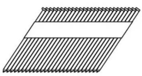 |  |  |
| NR1890DR | ||
| Plastic-collated strip nailsFull-head nails | Min. Max. | |
 | 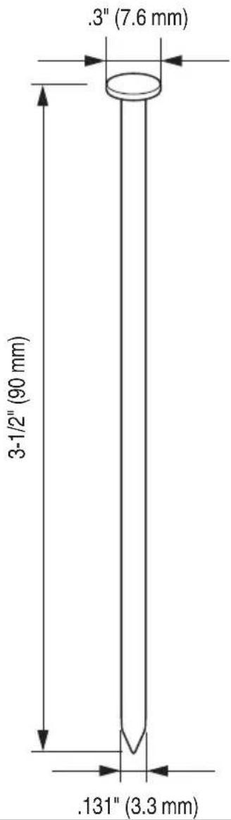 | |
 | ||
ACCESSORIES

DANGER
● Accessories other than those shown below can lead to malfunction and resulting injuries.
STANDARD ACCESSORIES
| NR1890DCNR1890DR(LSRK) |  1 1 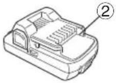 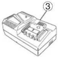 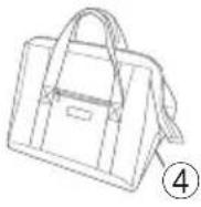 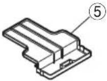 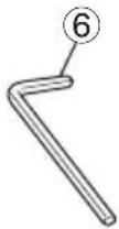  1 Safety glasses 12 Battery (BSL1830C) 23 Battery Charger (UC18YFSL) 14 Contractor bag 15 Battery cover (Code No. 329897) 16 Allen wrench for M5 screw 17 Allen wrench for M4 screw 1 1 Safety glasses 12 Battery (BSL1830C) 23 Battery Charger (UC18YFSL) 14 Contractor bag 15 Battery cover (Code No. 329897) 16 Allen wrench for M5 screw 17 Allen wrench for M4 screw 1 |
| NR1890DCNR1890DR(LYCK) |  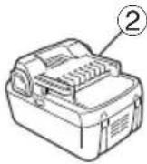 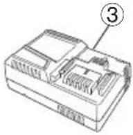 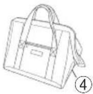 1 1   1 Safety glasses 12 Battery (BSL1860) 13 Battery Charger (UC18YSL3) 14 Contractor bag 15 Battery cover (Code No. 329897) 16 Allen wrench for M5 screw 17 Allen wrench for M4 screw 1 1 Safety glasses 12 Battery (BSL1860) 13 Battery Charger (UC18YSL3) 14 Contractor bag 15 Battery cover (Code No. 329897) 16 Allen wrench for M5 screw 17 Allen wrench for M4 screw 1 |
OPTIONAL ACCESSORIES
sold separately
○ BATTERY (BSL1830C) ○ BATTERY (BSL1860)
NOTE
Accessories are subject to change without any obligation on the part of HITACHI.
APPLICATIONS
○ Floor and wall framing.
○ Truss build-up, Window build-up.
○ Subfl ooring and roof decking.
○ Wall sheathing.
○ Mobile home and modular housing construction.
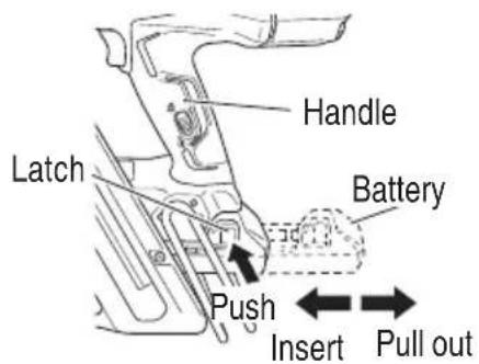
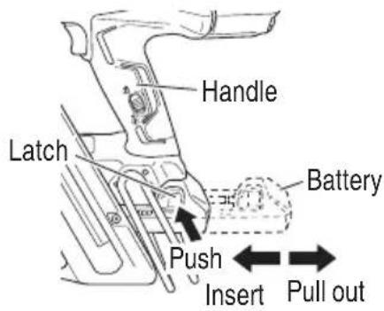
REMOVAL AND INSTALLATION METHOD OF BATTERY
CAUTION
● Be sure keep the fingers away from the trigger and push lever away from the wood.
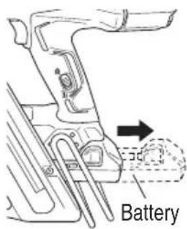
○ How to install the battery.
Align the battery with the groove in tool handle and slip it into place.
Always insert it all the way until it locks in place with a little click, If not, it may accidentally fall out of the tool, causing injury to you or someone around you.
○ How to remove the battery.
Withdraw battery from the tool handle while pressing the latch (2 pcs) of the battery.
CHARGING METHOD
NOTE
Before plugging into the receptacle, make sure the following points.
○ The power source voltage is stated on the nameplate.
○ The cord is not damaged.
WARNING
Do not charge at voltage higher than indicated on the nameplate.
If charged at voltage higher than indicated on the nameplate, the charger will burn up.
- Connect the charger's power cord to a receptacle. When the power cord is connected, the charger's pilot lamp will blink in red. (At 1-second intervals)
WARNING
Do not use the electrical cord if damaged. Have it repaired immediately.
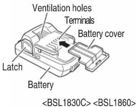
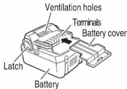
- Insert the battery to the battery charger.
Insert the battery into the battery charger as shown in Fig. 1, 2.
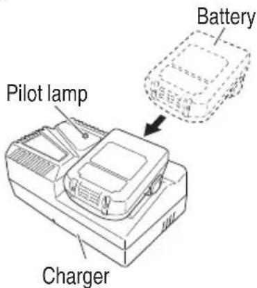
Fig. 1

Fig. 2
- Charging
When the battery is connected to the battery charger, charging will commence and the pilot lamp will light in red. (See Table 2)
NOTE
If the pilot lamp flikers in red, pull out the plug from the receptacle and check if the battery is properly mounted.
When the battery is fully charged, the pilot lamp will blink in red slowly. (At 1-second intervals) (See Table 2)
(1) Pilot lamp indication
The indications of the pilot lamp will be as shown in Table 2, according to the condition of the charger or the rechargeable battery.
Table 2
| Indications of the pilot lamp | ||||
| Pilot lamp(red) | Before charging Blinks | Lights for 0.5 seconds. Does not light for 0.5 seconds. (off for 0.5 seconds) | ||
| While charging Lights | Lights continuously | |||
| Charging complete | Blinks | Lights for 0.5 seconds. Does not light for 0.5 seconds. (off for 0.5 seconds) | ||
| Overheat standby | Blinks | Lights for 1 second. Does not light for 0.5 seconds. (off for 0.5 seconds) | Battery overheated.Unable to charge.(Charging will commence when battery cools) | |
| Charging impossible | Flickers | Lights for 0.1 seconds. Does not light for 0.1 seconds. (off for 0.1 seconds) | Malfunction in the battery or the charger | |
(2) Regarding the temperature of the rechargeable battery.
The temperatures for rechargeable batteries are as shown in the Table 3, and batteries that have become hot should be cooled for a while before being recharged.
Table 3 Recharging ranges of batteries
| Rechargeable batteries | Temperatures at which the battery can be recharged |
| BSL1830C | 32^ – 104^ (0^ – 40^) |
(3) Regarding recharging time (At 68°F (20°C))
Table 4 Charging time
| Battery\Charger | UC18YFSL |
| BSL1830C | Approx. 45 min. |
NOTE
The charging time may vary according to temperature and power source voltage.
When inserting a battery in the charger, the charge indicator lamp will blink in blue.
When the battery becomes fully recharged, the charge indicator lamp will light up in green.(See Table 5)
(1) Charge indicator lamp indication
The indications of the charge indicator lamp will be as shown in Table 5, according to the condition of the battery charger or the battery.
Table 5
| Indications of the charge indicator lamp | ||||
| Charge indicator lamp (RED / BLUE / GREEN / PURPLE) | Before charging | Blinks (RED) | Lights for 0.5 seconds. Does not light for 0.5 seconds.(off for 0.5 seconds) | Plugged into power source |
| While charging | Blinks (BLUE) | Lights for 0.5 seconds. Does not light for 1 second.(off for 1 second) | Battery capacity at less than 50% | |
| Blinks (BLUE) | Lights for 1 second. Does not light for 0.5 seconds.(off for 0.5 seconds) | Battery capacity at less than 80% | ||
| Lights (BLUE) | Lights continuously | Battery capacity at more than 80% | ||
| Charging complete | Lights (GREEN) | Lights continuously(Continuous buzzer sound: about 6 seconds) | ||
| Overheat standby | Blinks (RED) | Lights for 0.3 seconds. Does not light for 0.3 seconds.(off for 0.3 seconds) | Battery overheated. Unable to charge. (Charging will commence when battery cools) | |
| Charging impossible | Flickers (PURPLE) | Lights for 0.1 seconds. Does not light for 0.1 seconds.(off for 0.1 seconds)(Intermittent buzzer sound: about 2 seconds) | Malfunction in the battery or the charger | |
(2) Regarding the temperature of the rechargeable battery.
The temperatures for rechargeable batteries are as shown in the Table 6, and batteries that have become hot should be cooled for a while before being recharged.
Table 6
| Rechargeable batteries | Temperatures at which the battery can be recharged |
| BSL1860 | 14°F – 122°F(-10°C – 50°C) |
(3) Regarding recharging time (At 68°F (20°C))
Table 7 Charging time
| Battery\Charger | UC18YSL3 |
| BSL1860 | Approx. 38 min. |
NOTE
The recharging time may vary according to the ambient temperature.
- Disconnect battery charger from the receptacle.

CAUTION
Do not pull the plug out of the receptacle by pulling on the cord.
Make sure to grasp the plug when removing from receptacle to avoid damaging cord.
5. Remove the battery from the battery charger.
Supporting the battery charger with hand, pull out the battery from the battery charger.
NOTE
Be sure to pull out the battery from the battery charger after use, and then keep it.
Regarding electric discharge in case of new batteries, etc.
As the internal chemical substance of new batteries and batteries that have not been used for an extended period is not activated, the electric discharge might be low when using them the first and second time. This is a temporary phenomenon, and normal time required for recharging will be restored by recharging the batteries 2 – 3 times.
How to make the batteries perform longer
(1) Recharge the batteries before they become completely exhausted.
When you feel that the power of the tool becomes weaker, stop using the tool and recharge its battery. If you continue to use the tool and exhaust the electric current, the battery may be damaged and its life will become shorter.
(2) Avoid recharging at high temperatures.
A rechargeable battery will be hot immediately after use. If such a battery is recharged immediately after use, its internal chemical substance will deteriorate, and the battery life will be shortened. Leave the battery and recharge it after it has cooled for a while.
CAUTION
- When the battery charger has been continuously used, the battery charger will be heated, thus constituting the cause of the failures. Once the charging has been completed, give 15 rest until the next charging.
- If the battery is charged while it is heated because it has been left for a long time in a location subject to direct sunlight or because the battery has just been used, the pilot lamp of UC18YFSL charger lights for 1 second, does not light for 0.5 seconds (off for 0.5 seconds) or the charge indicator lamp of UC18YSL3 charger lights for 0.3 seconds, does not light for 0.3 seconds (off for 0.3 seconds). In such a case, first let the battery cool, then start charging.
- When the pilot lamp or charge indicator lamp flickers (at 0.2-second intervals), check for and take out any foreign objects in the charger's battery installation hole. If there are no foreign objects, it is probable that the battery or charger is malfunctioning. Take it to your authorized Service Center.
HOW TO RECHARGE USB DEVICE
WARNING
- Prior to use, check the connecting USB cable for any defect or damage.
Using a defective or damaged USB cable can cause smoke emission or ignition.
○ When the product is not being used, cover the USB port with the rubber cover.
Buildup of dust etc. in the USB port can cause smoke emission or ignition.
NOTE
☐ The time required for charging will be longer a USB device and battery are being simultaneously charged.
- There may be an occasional pause during USB recharging.
When a USB device is not being charged, turn the USB power switch OFF and remove the USB device from the charger.
Failure to do so may not only reduce the battery life of a USB device, but may also result in unexpected accidents.
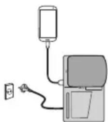
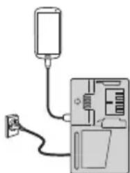
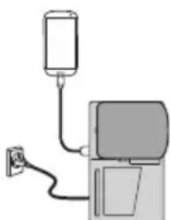
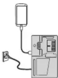
(1) Select a charging method
Depending on the charge method selected, either the battery is inserted into the charger or the power cord is plugged into an outlet.
○ Charging a USB device by battery (Fig. 3-a)
minuteCharging a USB device from a electrical outlet (Fig. 3-b)
○ Charging a USB device and battery from a electrical outlet (Fig. 3-c)
natural_image
Simple line drawing of a device with a plug and cable, no text or symbols presenta
natural_image
Diagram of a device with a plug connected to a device via tubing (no text or symbols visible)b
natural_image
Simple line drawing of a device with a battery and cable, no text or symbols presentC
Fig. 3
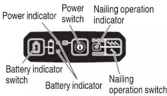
(2) Turn the USB power switch ON (Fig. 4) When you turn the USB power switch ON, the USB power indicator lamp will light up.

Fig.4
(3) Connect the USB cable. (Fig. 4)
Pull back the rubber cover and firmly plug commercially available USB cable (appropriate to the device being charged) into the USB port.
When the power cord is not plugged into an outlet and the battery runs out of power, power output will stop and the USB power indicator lamp will shut off.
When the USB power indicator lamp goes out, change the battery or plug the power cord into an electrical outlet.
(4) When charging is completed
○ The USB power indicator lamp will not go out when a USB device has been completely charged.
To verify charge status, check the USB device.
Turn the USB power switch OFF and unplug the power cord from the electrical outlet. (Fig. 4)
○ Remove the battery from the charger and place the rubber cover over the USB port.
BEFORE OPERATION
Read section titled "SAFETY" (pages 5 – 12).
Make sure of the followings before operation.
PREPARING THE BATTERY
Read section titled "SAFETY, IMPORTANT SAFETY INSTRUCTIONS FOR BATTERY CHARGER" (page 9).
You must charge the battery before use.
The charging method of battery is shown in page 18 - 21.

natural_image
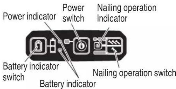
Technical line drawing of a mechanical assembly with an arrow indicating direction (no text or symbols present)(1) Power switch ON Under the condition of "Power switch OFF", push and hold on Power switch more than 1 second, then power indicator lights in Green.
NOTE
- Do not press the push lever and/or pull the trigger during the process of turning the power switch ON. Doing so will prevent the power switch from turning ON.
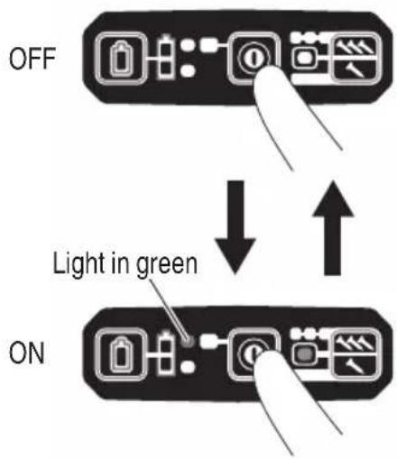
(2) Power switch OFF Under the condition of "Power switch ON", push and hold on Power switch more than 1 second, then power indicator goes off. Under the condition of "Power switch ON", functions below are active.
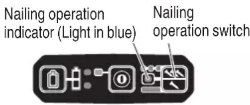
(3) Select Nailing operation mode
(Full sequential actuation / Contact actuation)
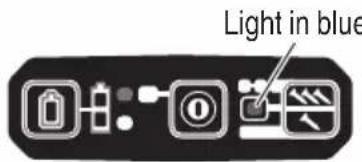
After power switch turn ON, always set in Full sequential actuation mode as initial. (Nailing operation indicator light in blue.)
Light in blue
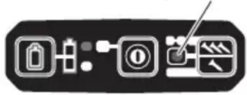
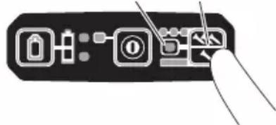
To change nailing operation mode, push Nailing operation switch once. Every pushing, mode will change between "Full sequential" and "Contact".
Lighting (Blue):
FULL SEQUENTIAL ACTUATION MECHANISM,
Blinking (Blue):
CONTACT ACTUATION MECHANISM
(4) Check Remaining battery level
When pressing the battery indicator switch, the battery indicator shows Remaining battery level by status of LED lamp as below.
| Status of indicator | |
 | The battery remaining power is enough. |
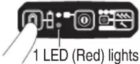 | The battery remaining power is about half. |
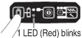 | The battery remaining power is nearly empty. Recharge the battery as soon as possible. |
(5) Other functions
In case of operation error, LED lamps show as below.
| Status of indicator | |
 2 LEDs (Red) blink2 LED lights blink in an interval.In case of too hot condition, Blink in 0.5 second interval.In case of too cold condition, Blink in 0.25 second interval. After 10 seconds, LED lights and Power switch automatically turn off . 2 LEDs (Red) blink2 LED lights blink in an interval.In case of too hot condition, Blink in 0.5 second interval.In case of too cold condition, Blink in 0.25 second interval. After 10 seconds, LED lights and Power switch automatically turn off . | Machine is in too cold (below 23°F (-5°C) or too hot condition.Allow the nailer to cool or warm-up thoroughly in adequate condition. |
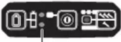 2 LEDs blink in Orange, after about 10 seconds, automatically turn off Power switch. 2 LEDs blink in Orange, after about 10 seconds, automatically turn off Power switch. | Contact Hitachi for replacement. |
TESTING THE NAILER

DANGER
- Operators and others in work area MUST wear safety glasses with side shields which conforms to ANSI Z87.1 specifications.

WARNING
● Make sure the trigger is locked when not fi ring nails.
This Nailer has a lock mechanism to prevent the nails from being fi red.
Set the lock lever at the 🔒 position to lock the trigger.
Slide the lock lever to the ☐ position when the Nailer is to be used, and to the ☐ position when it is not in use.

● Never use Nailer unless push lever is operating properly.
The machine employs a preventive mechanism for unloaded operation.
The machine enters a state where the push lever cannot be pushed up. This takes place when the magazine is not loaded with nails or when the remaining number of nails becomes less than 6 or 9.
CAUTION
- Use caution not to throw the push lever tip onto wood.
Before actually beginning the nailing work, test the Nailer by using the checklist below. Conduct the tests in the following order.
If abnormal operation occurs, stop using the Nailer and contact a Hitachi authorized service center immediately.
(1) REMOVE ALL NAILS AND BATTERY FROM NAILER.
□ ALL SCREWS MUST BE TIGHTENED.
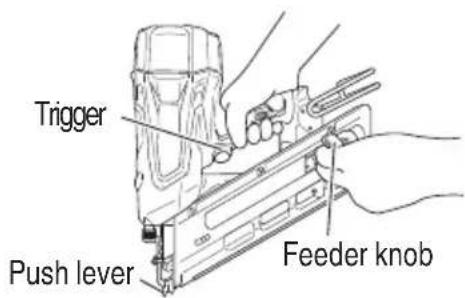
☐ THE PUSH LEVER AND TRIGGER MUST MOVE SMOOTHLY with pulling back the feeder knob.
(2) Installing the battery.
Do not operate the push lever or trigger while installing the battery.
(3) Turn on the Power switch.
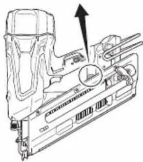
natural_image
Technical line drawing of a mechanical component with an arrow indicating direction (no text or symbols present)Turn on the Power switch by push and hold on Power switch more than 1 second.
Make sure the power indicator is lighting in green, and nailing operation indicator is lighting in blue. (FULL SEQUENTIAL ACTUATION MECHANISM,)
NOTE
- Do not press the push lever and/or pull the trigger during the process of turning the power switch ON. Doing so will prevent the power switch from turning ON.
[Auto power off]
When the power is turned on but the Nailer is not used for 30 minutes, the Nailer is automatically turned off. To turn on again, press the power switch.
![HITACHI NR1890DR - [Auto power off] - 1](/content/2026/04/660772/images/a634da6101081ade81480fcde20219c3c757637d8a431c1d57dd8e594cf33993.jpg)
WARNING
Never leave the Nailer with the power on. This could result in an accident.
Nailing operation indicator
Lighting (Blue):
FULL SEQUENTIAL ACTUATION MECHANISM, Blinking (Blue):
CONTACT ACTUATION MECHANISM)
Make sure the battery indicator is not blinking.
If the battery indicator is blinking in red, the battery doesn't have enough power and it needs to be charged.
(4) Remove the finger from the trigger and press the push lever against the workpiece with pulling back the feeder knob.
(5) Separate the push lever from the workpiece.
Next, point the nailer downward, with pulling back the feeder knob, pull the trigger and then wait in that position for 5 seconds or longer.
(6) ① Without touching the trigger, depress the push lever against the workpiece with pulling back the feeder knob.
Next, pull the trigger.
② Hold the trigger back and depress the push lever against the workpiece again.
③ Separate the finger from the trigger. Next, ① is operated again.
(7) Separate the push lever from the workpiece, pull the trigger.
Depress the push lever against the workpiece within 2 seconds.
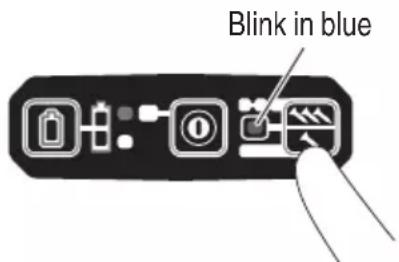
(8) Set the nailing operation indicator blinking ON mode. (CONTACT ACTUATION MECHANISM)
Push the nailing operation switch once, make sure that the indicator is blinking Blue.
Blink in blue

Separate the push lever from the workpiece, pull the trigger.
Depress the push lever against the workpiece within 2 seconds.
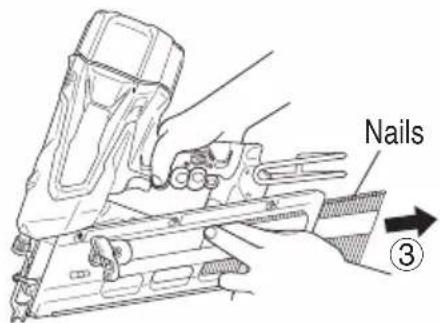
(9) If no abnormal operation is observed, you may load nails in the Nailer.
Drive nails into the workpiece that is the same type to be used in the actual application.
● When loading nails into Nailer,
1) remove battery from the nailer;
2) do not pull trigger;
3) do not depress push lever; and
4) keep nailer pointed downward.
2-Action Nail Feeding!
(1) Insert nail strip into the back of the magazine.
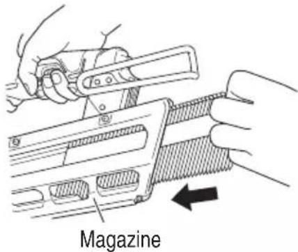
(2) Slide the nail strip forward in the magazine.
natural_image
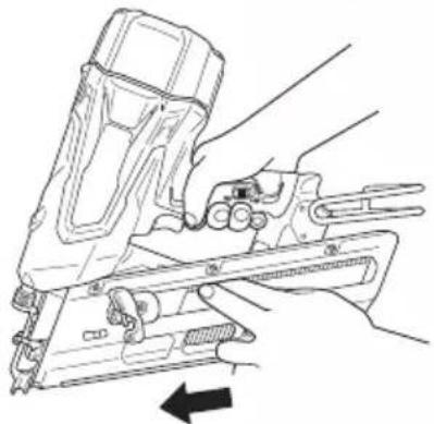
Line drawing of a hand using a power tool to handle a mechanical component, with no visible text or symbols.(3) Pull the nail feeder (B) back to engage the feeder knob to the nail strip.
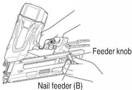
NOTE:
- Quietly push the nail feeder (B) and feeder knob against the nail.
If the nail feeder (B) and feeder knob are released from backward the magazine and bumped against the nail, the connecting paper or plastic of the nail can be damaged.
● Use nail strip of more than 10 nails.(NR1890DC)
● Use an unbroken nail strip with nails of all the same length. (NR1890DR)
The Nailer is now ready to operate.
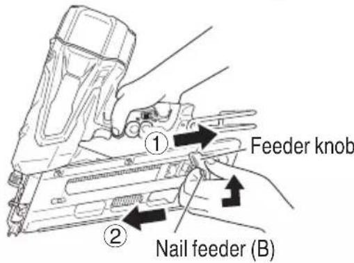
Removing the nails:
① Pull the feeder knob backward.
② Return the feeder knob forward quietly while pushing the nail feeder (B).
③ Pull out nails from the back of the magazine.
NAILER OPERATION
Read section titled "SAFETY" (pages 5 – 12).
DANGER

- Operators and others in work area MUST wear safety glasses with side shields which conforms to ANSI Z87.1 specifications.
WARNING

- NEVER point tool at yourself or others in work area. - Keep fingers AWAY from trigger when not driving nails to avoid accidental firing.
- Do not use the electrical cord if damaged. Have it repaired immediately.
● Choice of triggering method is important.
Please read and understand "METHODS OPERATION" found below.
● Before starting work, check the nailing operation switching device.
This Hitachi nailer includes a nailing operation switching device.
Before starting work, make switching device is properly set.
If the switching device is not set properly, the nailer will not operate correctly.
● Never place your face, hands or feet near fi ring head when using.
- Do not drive nails on top of other nails or with Nailer at too steep of an angle; nails can ricochet and hurt someone.
- Do not drive nails into thin boards or near corners and edges of workpiece. Nails can be driven through or away from workpiece and hit someone.
● Never drive nails from both sides of a wall at the same time. Nails can be driven into and through the wall and hit a person on the opposite side.
● Never use Nailer which is defective or operating abnormally.
● Do not use Nailer as hammer.
- Remove all remaining fasteners and battery from nailer when:
1) doing maintenance and inspection;
2) checking proper operation of push and trigger;
3) cleaning a jam;
4) it is not in use;
5) leaving work area;
6) moving it to another location; and
7) handing it to another person.
- Remove battery from Nailer when:
1) loading nails;
2) turning the adjuster.
This Hitachi nailer is equipped with a nailer operation switching device.
Use FULL SEQUENTIAL ACTUATION MECHANISM or CONTACT ACTUATION MECHANISM in accordance with the work to be performed.
Explanation of the various nailing operations
- FULL SEQUENTIAL ACTUATION MECHANISM:
First, press the push lever against the wood; next, pull the trigger to drive the nail.
Follow the same sequence to continue driving nails.
After nailing once, nailing will not be possible again until the trigger is released and pressed again.
○ CONTACT ACTUATION MECHANISM:
O ECONTACT ACTUATION can follow two different sequences, depending on your use.
To drive several nails:
- Pull the trigger.
- Press the push lever against the wood to drive the nail.
s u3r ef thehriager is held back, a nail will be driven each time the push lever is pressed against the wood.
To drive a single nail:
- Press the push lever against the wood.
- Pull the trigger to drive the nail.
- Remove your finger from the trigger and remove the nailer from the wood.
The machine employs a preventive mechanism for unloaded operation.
The machine enters a state where the push lever cannot be pushed up. This takes place when the magazine is not loaded with nails or when the remaining number of nails becomes less than 6 or 9.
CAUTION
- Use caution not to throw the push lever tip onto wood when the push lever cannot be pushed up.
METHODS OF OPERATION
This Nailer is equipped with the push lever and does not operate unless the push lever is depressed.
There are two methods of operation to drive nails with this Nailer.
They are:
- Intermittent operation (Trigger fire):
- Continuous operation (Push lever fire):
(1) Intermittent operation (Trigger fire)
Use the FULL SEQUENTIAL ACTUATION MECHANISM setting.
WARNING
- For intermittent operation, Set the nailing operation switch to FULL SEQUENTIAL ACTUATION MECHANISM (Nailing operation indicator is light in blue.) (i.e. Set to SINGLE ACTUATION MECHANISM.)
● To avoid double firing or accidental firing due to recoil.
1) Set to FULL SEQUENTIAL ACTUATION MECHANISM.
2) Pull the trigger rapidly and firmly.
① Set the nailing operation switch to FULL SEQUENTIAL ACTUATION MECHANISM (Nailing operation indicator is light in blue.)
(to set to FULL SEQUENTIAL ACTUATION MECHANISM). 27
(Set the switching device to the nailing operation indicator light in blue mode completely as shown in the diagram. Otherwise, it will be set to CONTACT ACTUATION MECHANISM.)
② Position the nail outlet on the workpiece with finger off the trigger.
③ Depress the push lever firmly until it is completely depressed.
④ Pull the trigger to drive a nail.
⑤ Remove finger from the trigger and lift the tool off the wood surface completely.
To continue nailing in a separate location, move nailer along the wood, repeating steps ② - ⑤ as required.
① Set the nailing operation switch to CONTACT ACTUATION MECHANISM (Nailing operation indicator is blink in blue.)
(to set to CONTACT ACTUATION MECHANISM).
(Set the switching device to the nailing operation indicator blink in blue completely as shown in the diagram. Otherwise, it will not operate properly.)
② Pull the trigger with the Nailer off the workpiece.
③ Depress the push lever against the workpiece to drive a nail.
④ Move the Nailer along the workpiece with a bouncing the motion.
Each depression of the push lever will drive a nail.
As soon as the desired number of nails have been driven, remove finger from the trigger.
NOTE
Operations ③ and ④ should be done within
2 seconds of each other. If more than 2 seconds pass after ③, the Nailer will not work properly. If this happens, retry from ③.
Operations ② and ③ should be done 2 seconds of each other. If more than 2 seconds pass after ②, the Nailer will not work properly. If this happens, retry from ②.

(2) Continuous operation (Push lever fire)
Using CONTACT ACTUATION MECHANISM
WARNING
● To avoid double firing or accidental firing due to recoil.
1) Do not press the nailer against the wood with excessive force.
2) Separate the nailer from the wood as it recoils after nailing.
Nailing operation indicator (blink in blue) Nailing operation switch
natural_image
Pure electrical circuit lines without any symbols
WARNING
- Keep your finger off the trigger except during nailing operation, because serious injury could result if the push lever accidentally contacts you or others in work area.
- Keep hands and body away from the discharge area. This Hitachi nailer may bounce from the recoil of driving a nail and unwanted subsequent nail may be driven, possibly causing injury.
NOTE
- If all warnings and instructions are followed, safe operation is possible with all two systems: FULL SEQUENTIAL ACTUATION MECHANISM, CONTACT ACTUATION MECHANISM.
● Always handle nails and package carefully. If nails are dropped, collating bond may be broken, which will cause mis-feeding and jamming.
● After nailing:
1) remove battery from the Nailer;
2) remove all nails from the Nailer;
ADJUSTING THE NAILING DEPTH
To assure that each nail penetrates to the same be sure that the Nailer is always held firmly against workpiece.
If nails are driven too deep or shallow into the workpiece, adjust the nailing in the following order.
① Remove the battery from the Nailer.
② If nails are driven too deep, turn the adjuster to the shallow side.
Adjustments are in half-turn increments.

flowchart
graph TD
    A["② Too Shallow"] --> B["Turn Adjuster"]
    C["② Too Deep"] --> D["Turn Adjuster"]
    B --> E["Flush"]
    D --> F["Flush"]
If nails are driven too shallow, turn the adjuster to the deep side.
③ Stop turning the adjuster when a suitable position is reached for a nailing test.
④ Connect the battery to the Nailer. ALWAYS WEAR SAFETY GLASSES. Perform a nailing test.
⑤ Remove the battery from the Nailer.
⑥ Choose a suitable position for adjuster.
USING THE HOOK
WARNING
depth. When using the hook, turn off the power switch (green light "OFF"). Pay sufficient attention so that the main equipment does not fall. If the toll falls, there is a risk of accident.
Hook can be installed on the left or right side.
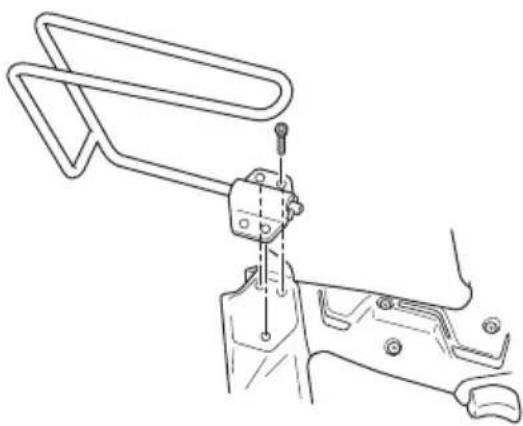
(1) Securely hold the main unit and remove the screw using a screwdriver.

natural_image
Line drawing of a mechanical clamp or bracket assembly (no text or symbols)(2) Remove the hook and hook plate.
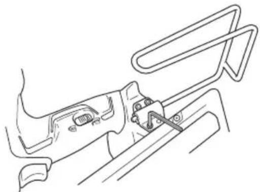
natural_image
Technical line drawing of a mechanical clamp or bracket assembly (no text or symbols)(3) Install the hook on the other side and securely fasten with screw.
natural_image
Line drawing of a mechanical component with no visible text or symbolsCLEARING A JAM
If nails are jammed in firing head, remove it, and adjust the nailing in the following order.
CAUTION
- Remove the battery from the Nailer.
① Remove the battery from the Nailer.
② Remove all nails.
③ Remove the M5 bolts with wrench.

natural_image
Illustration of a hand using a wrench to adjust or install a mechanical component (no text or symbols present)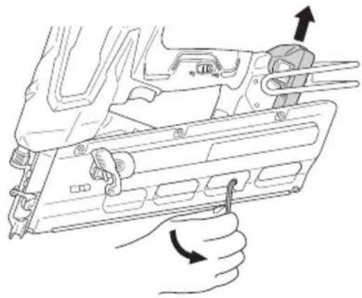
natural_image
Line drawing of a hand holding a firearm component with arrows indicating movement (no text or symbols)
natural_image
Technical line drawing of a fastener assembly with no visible text or symbols⑤ Attach the magazine to the injector and tighten with the M5 bolt.
NOTE
- In case of frequent jam, contact a Hitachi authorized service center.
④ Pull magazine away from the fi ring head, and clear jam.
CAUTION
● NEVER hit the driver blade.
● NEVER point the tool at yourself or another person, to avoid risk of injury by mis-fi ring.
Even if the battery is removed from the nailer, there is still energy of compressed air remaining inside.
MAINTENANCE
NOTE
The information contained in this Manual is designed to assist you in the safe maintenance of the Nailer.
Some illustrations in this Manual may show details or attachments that differ from those on your own Nailer.
MAINTENANCE AND INSPECTION
Read section titled "SAFETY" (pages 5 – 12).

WARNING
- Remove battery and all remaining fasteners from Nailer when:
1) doing maintenance and inspection; and
2) clearing a jam.
- Inspecting the magazine
① Remove battery.
② Clean the magazine. Remove dust and wooden chips which may have accumulated in the magazine.
CAUTION
- Check that the nail feeder slides smoothly by pulling it with fi nger.
If not smooth, nails can be driven at an irregular angle and hurt someone.
- Storing
- Do not store the Nailer, and battery in a cold weather environment.
Keep them in a warm area.
When not in use, the Nailer, and battery should be stored in a warm and dry place.
Keep it out of reach of children.
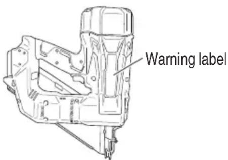
- WARNING LABEL
Change the WARNING LABEL if missing or damaged.
A new WARNING LABEL is available from a Hitachi authorized service center.
-
Maintenance chart (See page 32)
-
Operator troubleshooting (See page 32 – 33)
- Disposal of the exhausted battery

WARNING
Do not dispose of the exhausted battery. The battery must explode if it is incinerated. The product that you have purchased contains a rechargeable battery. The battery is recyclable. At the end of it's useful life, under various state and local laws, it may be illegal to dispose of this battery into the municipal waste stream. Check with your local solid waste officials for details in your area for recycling options or proper disposal.
- Storage
Storing in a place below 104^ F ( 40^ C) and out of the reach of children.
NOTE
Storing lithium-ion batteries
Make sure the lithium-ion batteries have been fully charged before storing them.
Prolonged storage (3 months or more) of batteries with a low charge may result in performance deterioration, significantly reducing battery usage time or rendering the batteries incapable of holding a charge.
However, significantly reduced battery usage time may be recovered by repeatedly charging and using the batteries two to five times.
If the battery usage time is extremely short despite repeated charging and use, consider the batteries dead and purchase new batteries.
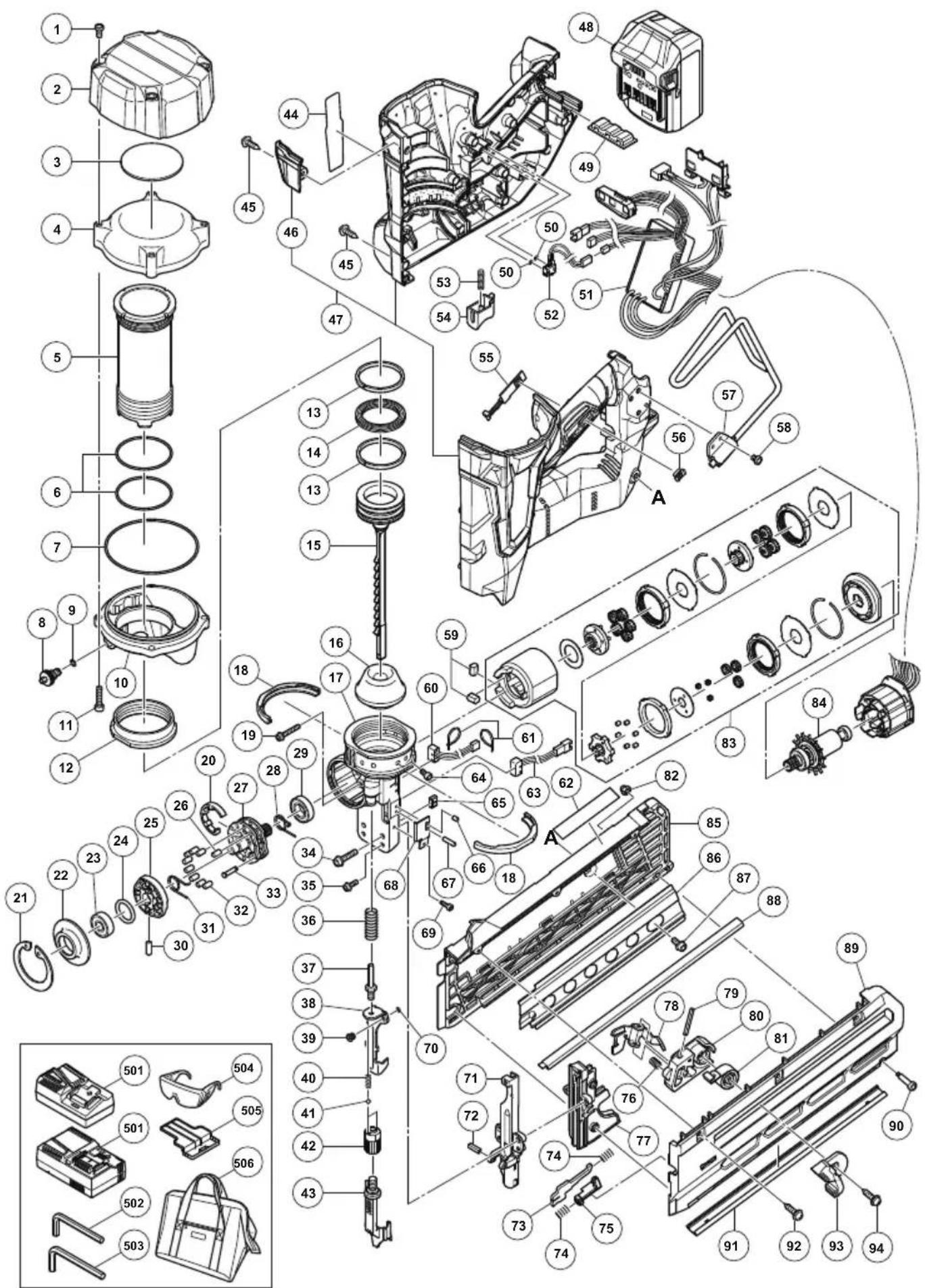
- Service parts list
CAUTION
● Repair, modification and inspection of Hitachi Power Tools must be carried out by a Hitachi Authorized Service Center.
This Parts List will be helpful if presented with the tool to the Hitachi Authorized Service Center when requesting repair or other maintenance. In the operation and maintenance of power tools, the safety regulations and standards prescribed in each country must be observed.
MODIFICATIONS
Hitachi Power Tools are constantly being improved and modified to incorporate the latest technological advancements.
Accordingly, some parts may be changed without prior notice.
Important notice on the batteries for the Hitachi cordless power tools
Please always use one of our designated genuine batteries. We cannot guarantee the safety and performance of our cordless power tool when used with batteries other than these designated by us, or when the battery is disassembled and modified (such as disassembly and replacement of cells or other internal parts).
SERVICE AND REPAIRS
WARNING
- Only service personnel trained by Hitachi, distributor or employer shall repair the Nailer.
- Use only parts supplied or recommended by Hitachi for repair.
All quality Nailers will eventually require servicing or replacement of parts because of wear from normal use.
NOTE
Specifications are subject to change without any obligation on the part of HITACHI.
Maintenance chart
| ACTION WHY HOW | ||
| Clean magazine and feeder mechanism. | Prevent a jam. Blow clean daily. | |
| Keep push lever working properly. | Promote operator safety and efficient Nailer operation. | Blow clean daily. |
Operator troubleshooting
Most minor problems can be resolved quickly and easily using the table below. If problems persist, contact a Hitachi authorized service center for assistance.
| PROBLEM | CHECK METHOD | CORRECTION |
| Power switch doesn’t turn on. Turn on once, but turn off automatically. | Low battery charge. | Charge the battery. |
| Damaged internal electronics. | Contact Hitachi for replacement. | |
| Push lever and/or trigger is ON state? | Keep push lever and trigger in OFF state. | |
| Keep no operation over 30 minutes? (Auto-power off function) | Push and hold power switch more than 1 second to switch “ON” | |
| Nailer doesn’t operate (Power switch ON). | Nailer not enough pressed against workpiece. | Hold nailer firmly and press to the workpiece completely. |
| Trigger not enough pulled. | Pull the trigger firmly. | |
| More than 2 seconds pass from push lever ON to trigger ON (or trigger ON to push lever ON). | Make sure that less than 2 seconds pass between push lever ON and trigger ON (or between trigger ON and push lever ON). | |
| Preventive mechanism activated. (No nails, or too few fasteners remaining) | Reload the nails into magazine. | |
| Lock lever(Trigger lock function) is “ON” position. | Set Lock lever to “OFF” position. (Refer to page 23 – 24) | |
| Machine is too cold (below 23°F (-5°C)) or too hot. | Allow the nailer to cool or warm-up throughly in adequate condition. | |
| Damaged internal electronics. | Contact Hitachi for replacement. | |
| PROBLEM CHECK METHOD CORRECTION | ||
| Nailer operates, but no nail is driven. Magazine is dirty. Blow and wipe clean the magazine. | ||
| Weak drive. Slow to cycle. | Check for proper nails. Use only recommended nails. | Readjust according to page 29. |
| Check position of nailing depth adjustment adjuster. | Readjust according to page 29. | |
| Driver blade worn? Contact Hitachi for replacement. | Readjust according to page 29. | |
| Compressed air pressure has become low. | Readjust according to page 29. | |
| Damaged internal electronics. Contact Hitachi for replacement. | Readjust according to page 29. | |
| Drives too deep. Check position of nailing depth adjustment adjuster. | Readjust according to page 29. | |
| Skipping nails. Intermittent feed. | Check for proper nails. Use only recommended nails. | Readjust according to page 29. |
| Nail feeder damaged? Replace nail feeder. | Readjust according to page 29. | |
| Ribbon spring weakened or damaged? | Replace ribbon spring. | |
| Driver blade worn or damaged? Contact Hitachi for replacement. | Readjust according to page 29. | |
| Nails jam. Driven nail is bent. | Check for proper nails. Use only recommended nails. | Readjust according to page 29. |
| Driver blade worn or damaged? Contact Hitachi for replacement. | Readjust according to page 29. | |
INFORMATION IMPORTANTE

natural_image
Simple line drawing of a device with a battery and cable, no text or symbols presenta
natural_image
Diagram of a device with a plug and cable, no text or symbols presentb

natural_image
Simple line drawing of a device with a bulb and plug, no text or symbols presentC
Fig. 3
natural_image
Technical line drawing of a mechanical component with an arrow indicating direction (no text or symbols present)natural_image
Technical line drawing of a mechanical assembly with no visible text or symbolsnatural_image
Line drawing of a hand using a power tool to adjust or install a mechanical component, with no visible text or symbols.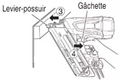
⚠ AVERTISSEMENT
natural_image
Line drawing of a mechanical clamp or bracket assembly (no text or symbols)natural_image
Technical line drawing of a mechanical clamp or bracket assembly (no text or symbols)natural_image
Line drawing of a mechanical device with lever and bracket (no text or symbols)ÉLIMINATION D'UN BLOCAGE
natural_image
Illustration of a hand using a tool to adjust or install a mechanical component, no text or symbols presentnatural_image
Line drawing of a hand holding a device with arrows indicating motion (no text or symbols)ATTENTION
natural_image
Technical line drawing of a fastener assembly with no visible text or symbolsnatural_image
Line drawing of a hand using a power tool to adjust or install a component, with no visible text or symbols.natural_image
Line drawing of a mechanical clamp or bracket assembly (no text or symbols)natural_image
Technical line drawing of a mechanical clamp or bracket assembly (no text or symbols)natural_image
Line drawing of a mechanical device with adjustment knobs and lever mechanism (no text or symbols)EN CÁSO DE ATASCO
natural_image
Illustration of a hand using a tool to adjust or install a mechanical component, no text or symbols presentnatural_image
Line drawing of a hand holding a device with arrows indicating motion (no text or symbols)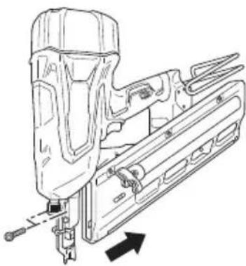
natural_image
Technical line drawing of a fastener assembly with mounting bracket and tool (no text or symbols)| ITEM NO. | PART NAME Q'TY | |
| 1 HEX. SOCKET BOLT M6 4 | ||
| 2 T O P C O V E R | 1 | |
| 3 RUBBER CUSHION (C) 1 | ||
| 4 C H A M B E R C | O | |
| 5 C Y L I N D E R | 1 | |
| 6 O-RING (I.D 55.5) 2 | ||
| 7 O-RING (I.D 94.5) 1 | ||
| 8 C H A R G E C A | P | |
| 9 O - R I N G ( S - 5 | ||
| 10 CHAMBER BASE 1 | ||
| 11 NYLOCK BOLT M6 | 4 | |
| 12 SPECIAL NUT M58 | 1 | |
| 13 SLIDE RING | 2 | |
| 14 X-RING | 1 | |
| 15 PISTON BLADE | 1 | |
| 16 PISTON BUMPER | 1 | |
| 17 NOSE | 1 | |
| 18 RUBBER CUSHION (A) | 2 | |
| 19 NYLOCK BOLT (W/FLANGE) M4×25 | 1 | |
| 20 FELT (P) | 1 | |
| 21 RETAINING RING D52 1 | ||
| 22 BEARING HOLDER | 1 | |
| 23 BALL BEARING 6000VVCMPS2L | 1 | |
| 24 O-RING (I.D 20.22) | 1 | |
| 25 POSITION DETECTOR | 1 | |
| 26 NEEDLE ROLLER D4.5 | 1 | |
| 27 PIN WHEEL | 1 | |
| 28 WHEEL SPRING (B) | 1 | |
| 29 BALL BEARING 6902VV | 1 | |
| 30 NEEDLE ROLLER D3 | 1 | |
| 31 WHEEL SPRING (A) | 1 | |
| 32 NEEDLE ROLLER D4 | 8 | |
| 33 PIN (A) | 1 | |
| 34 NYLOCK BOLT (W/FLANGE) M5×22 | 2 | |
| 35 NYLOCK BOLT (W/FLANGE) M4×14 | 2 | |
| 36 PUSHING LEVER SPRING (B) | 1 | |
| 37 SPECIAL BOLT M6 | 1 | |
| 38 PUSHING LEVER (B) | 1 | |
| 39 MAGNET | 1 | |
| 40 ADJUSTER SPRING | 2 | |
| 41 STEEL BALL D3.175 | 2 | |
| 42 ADJUSTER | 1 | |
| 43 PUSHING LEVER (A) | 1 | |
| 44 NAME PLATE | 1 | |
| 45 TAPPING SCREW (W/FLANGE) D4×20 | 14 | |
| 46 HOUSING (C) | 1 | |
| 47 HOUSING SET | 1 | |
| 48 BATTERY BSL1830C/BSL1860 | 1 | |
| 49 RUBBER CUSHION | 1 | |
| 50 O-RING (I.D 2.5) | 2 | |
| 51 WIRING | 1 | |
| 52 SWITCH CABLE (A) | 1 | |
| 53 SPRING (T) | 1 | |
| 54 TRIGGER | 1 | |
| 55 LEVER (C) | 1 | |
| 56 LEVER (A) | 1 | |
| 57 HOOK | 1 | |
| 58 LOW HEAD HEX. SOCKET BOLT M4×8 | 3 | |
| 59 BUMPER (B) | 2 | |
| 60 SENSOR (C) | 1 | |
| ITEM NO. | PART NAME Q'TY | |
| 61 WIRE BAND | 2 | |
| 62 CAUTION LABEL 1 | ||
| 63 SENSOR (B) | 1 | |
| E64 HEX. SOCKET HD. BOLT M5 | 1 | |
| 65 GUIDE PLATE HOLDER | 1 | |
| 66 ROLL PIN D2.5 | 1 | |
| 67 ROLL PIN D2.5×16 | 1 | |
| 68 GUIDE PLATE (P) | 1 | |
| 69 NYLOCK HEX. SOCKET HD. BOLT M3 | 1 | |
| 70 O-RING (S-4) | 1 | |
| 71 BLADE GUIDE(A) | 1 | |
| 72 ROLL PIN D3×20 | 1 | |
| 73 PUSHING LEVER STOPPER (A) | 1 | |
| 74 SPRING | 2 | |
| 75 PUSHING LEVER STOPPER (B) | 1 | |
| 76 SPRING | 1 | |
| 77 BLADE GUIDE (B) 1 | ||
| 78 NAIL FEEDER (A) 1 | ||
| 79 ROLL PIN D4×28 | 1 | |
| 80 NAIL FEEDER (B) 1 | ||
| 81 RIBBON SPRING 1 | ||
| 82 CAP NUT M3 | 1 | |
| 83 GEAR BOX | 1 | |
| 84 ROTOR | 1 | |
| 85 MAGAZINE COVER (B) | 1 | |
| 86 NYLOCK BOLT (W/FLANGE) M5 | 1 | |
| 87 MAGAZINE PLATE | 1 | |
| 88 NAIL RAIL | 1 | |
| 89 MAGAZINE COVER (A) | 1 | |
| 90 STEP BOLT M3 | 1 | |
| 91 MAGAZINE GUARD | 1 | |
| 92 TAPPING SCREW (W/FLANGE) D4×16 | 3 | |
| 93 FEEDER KNOB | 1 | |
| 94 TAPPING SCREW (W/FLANGE) D5×20 | 1 | |
| 501 | CHARGER(MODEL UC18YFSL/UC18YSL3) | 1 |
| 502 | HEX. BAR WRENCH 3MM | 1 |
| 503 | HEX. BAR WRENCH 4MM | 1 |
| 504 | PROTECTIVE GLASSES | 1 |
| 505 | BATTERY COVER 1 | |
| 506 | TOOL BAG | 1 |
| ITEM NO. | PART NAME Q'TY | |
| 1 HEX. SOCKET BOLT M6 4 | ||
| 2 T O P C O V E R | 1 | |
| 3 RUBBER CUSHION (C) 1 | ||
| 4 C H A M B E R C | O | |
| 5 C Y L I N D E R | 1 | |
| 6 O-RING (I.D 55.5) 2 | ||
| 7 O-RING (I.D 94.5) 1 | ||
| 8 C H A R G E C A | P | |
| 9 O - R I N G ( S - 5 | ||
| 10 CHAMBER BASE 1 | ||
| 11 NYLOCK BOLT M6 | 4 | |
| 12 SPECIAL NUT M58 | 1 | |
| 13 SLIDE RING | 2 | |
| 14 X-RING | 1 | |
| 15 PISTON | 1 | |
| 16 PISTON BUMPER | 1 | |
| 17 NOSE | 1 | |
| 18 RUBBER CUSHION (A) | 2 | |
| 19 NYLOCK BOLT (W/FLANGE) M4×25 | 1 | |
| 20 FELT (P) | 1 | |
| 21 RETAINING RING D52 1 | ||
| 22 BEARING HOLDER | 1 | |
| 23 BALL BEARING 6000VVCMPS2L | 1 | |
| 24 O-RING (I.D 20.22) | 1 | |
| 25 POSITION DETECTOR 1 | ||
| 26 NEEDLE ROLLER D4.5 | 1 | |
| 27 PIN WHEEL | 1 | |
| 28 WHEEL SPRING (B) | 1 | |
| 29 BALL BEARING 6902VV | 1 | |
| 30 NEEDLE ROLLER D3 | 1 | |
| 31 WHEEL SPRING (A) | 1 | |
| 32 NEEDLE ROLLER D4 | 8 | |
| 33 PIN (A) | 1 | |
| 34 NYLOCK BOLT (W/FLANGE) M5×22 | 2 | |
| 35 NYLOCK BOLT (W/FLANGE) M4×14 | 2 | |
| 36 PUSHING LEVER SPRING (B) | 1 | |
| 37 SPECIAL BOLT M6 | 1 | |
| 38 PUSHING LEVER (B) | 1 | |
| 39 MAGNET | 1 | |
| 40 ADJUSTER SPRING | 2 | |
| 41 STEEL BALL D3.175 | 2 | |
| 42 ADJUSTER | 1 | |
| 43 PUSHING LEVER (A) | 1 | |
| 44 NAME PLATE | 1 | |
| 45 TAPPING SCREW (W/FLANGE) D4×20 | 14 | |
| 46 HOUSING (C) | 1 | |
| 47 HOUSING SET | 1 | |
| 48 BATTERY BSL1830C/BSL1860 | 1 | |
| 49 RUBBER CUSHION | 1 | |
| 50 O-RING (I.D 2.5) | 2 | |
| 51 WIRING | 1 | |
| 52 SWITCH CABLE (A) | 1 | |
| 53 SPRING (T) | 1 | |
| 54 TRIGGER | 1 | |
| 55 LEVER (C) | 1 | |
| 56 LEVER (A) | 1 | |
| 57 HOOK | 1 | |
| 58 LOW HEAD HEX. SOCKET BOLT M4×8 | 3 | |
| 59 BUMPER (B) | 2 | |
| 60 SENSOR (C) | 1 | |
| ITEM NO. | PART NAME Q'TY | |
| 61 WIRE BAND | 2 | |
| 62 CAUTION LABEL 1 | ||
| 63 SENSOR (B) | 1 | |
| E64 HEX. SOCKET HD. BOLT M5 | 1 | |
| 65 GUIDE PLATE HOLDER | 1 | |
| 66 ROLL PIN D2.5 | 1 | |
| 67 ROLL PIN D2.5×16 | 1 | |
| 68 GUIDE PLATE (P) | 1 | |
| 69 NYLOCK HEX. SOCKET HD. BOLT M3 | 1 | |
| 70 O-RING (S-4) | 1 | |
| 71 BLADE GUIDE (A) 1 | ||
| 72 ROLL PIN D3×20 | 1 | |
| 73 PUSHING LEVER STOPPER (A) | 1 | |
| 74 SPRING | 2 | |
| 75 PUSHING LEVER STOPPER (B) | 1 | |
| 76 SPRING | 1 | |
| 77 BLADE GUIDE (B) 1 | ||
| 78 NAIL FEEDER | 1 | |
| 79 ROLL PIN D4×28 | 1 | |
| 80 NAIL FEEDER (B) 1 | ||
| 81 RIBBON SPRING 1 | ||
| 82 CAP NUT M3 | 1 | |
| 83 GEAR BOX | 1 | |
| 84 ROTOR | 1 | |
| 85 MAGAZINE COVER (B) | 1 | |
| 86 MAGAZINE PLATE | 1 | |
| 87 NYLOCK BOLT (W/FLANGE) M5 | 1 | |
| 88 NAIL RAIL (A) | 1 | |
| 89 MAGAZINE COVER (A) | 1 | |
| 90 STEP BOLT M3 | 1 | |
| 91 MAGAZINE GUARD | 1 | |
| 92 TAPPING SCREW (W/FLANGE) D4×16 | 3 | |
| 93 FEEDER KNOB | 1 | |
| 94 TAPPING SCREW (W/FLANGE) D5×20 | 1 | |
| 501 | CHARGER(MODEL UC18YFSL/UC18YSL3) | 1 |
| 502 | HEX. BAR WRENCH 3MM | 1 |
| 503 | HEX. BAR WRENCH 4MM | 1 |
| 504 | PROTECTIVE GLASSES | 1 |
| 505 | BATTERY COVER 1 | |
| 506 | TOOL BAG | 1 |

Please contact HITACHI KOKI U.S.A. LTD. at 1-800-59-TOOLS (toll free), or HITACHI AUTHORIZED POWER TOOL SERVICE CENTER regarding COLLECTION.

Pour le RAMASSAGE, contacter HITACHI KOKI U.S.A. LTD. au 1-800-59-TOOLS (appel gratuit), ou UN SERVICE APRÈS-VENTE D'OUTILS ÉLECTRIQUE AGRÉÉ PAR HITACHI.

Shinagawa Intercity Tower A, 15-1, Konan 2-chome, Minato-ku, Tokyo 108-6020, Japan
Distributed by

Hitachi Koki U.S.A., Ltd.
PO Box 970
Braselton, GA 30517

Hitachi Koki Canada Corp.
450 Export Blvd. Unit B, Mississauga ON L5S 2A4
- DANGER
- MAINTENANCE
- TABLE DES MATIÈRES
- Français
- Page Page
- SECURITE
- UTILISATION
- ENTRETIEN
- ÍNDICE
- Español
- Página Página
- DEFINITIONS OF SIGNAL WORDS
- SAFETY
- GENERAL POWER TOOL SAFETY WARNINGS
- WARNING
- SAFETY — Continued
- 4) Power tool use and care
- 5) Battery tool use and care
- 6) Service
- - WARNING -
- WARNING:
- NAILER SAFETY WARNINGS
- IMPORTANT SAFETY INSTRUCTIONS FOR USING NAILERS
- READ ALL INSTRUCTIONS
- OPERATORS AND OTHERS IN WORK AREA MUST WEAR SAFETY GLASSES WITH SIDE SHIELDS.
- NEVER POINT TOOL AT YOURSELF OR OTHERS IN WORK AREA.
- KEEP FINGERS AWAY FROM TRIGGER WHEN NOT DRIVING FASTENERS TO AVOID ACCIDENTAL FIRING.
- CHOICE OF TRIGGERING METHOD IS IMPORTANT.
- ALWAYS WEAR EAR AND HEAD PROTECTION.
- OPERATE WITHIN PROPER TEMPERATURE RANGE.
- STORE NAILER PROPERLY, AND BATTERY REMOVED.
- KEEP WORK AREA CLEAN.
- KEEP VISITORS AWAY.
- DRESS PROPERLY.
- CHECK PUSH LEVER BEFORE USE.
- KEEP ALL SCREWS AND COVERS TIGHTLY IN PLACE.
- DO NOT LOAD FASTENERS WITH TRIGGER OR PUSH LEVER DEPRESSED.
- KEEP FACE, HANDS AND FEET AWAY FROM FIRING HEAD DURING USE.
- PLACE NAILER PROPERLY ON WORKPIECE.
- BEFORE STARTING WORK, CHECK THE FASTENING OPERATION SWITCHING DEVICE.
- BE CAREFUL OF DOUBLE FIRE DUE TO RECOIL.
- ○ Intermittent operation (Trigger firing)
- ○ Continuous operation (Push lever firing)
- DO NOT DRIVE FASTENERS INTO THIN BOARDS OR NEAR CORNERS AND EDGES OF WORKPIECE.
- NEVER DRIVE FASTENERS FROM BOTH SIDES OF A WALL AT THE SAME TIME.
- CHECK FOR LIVE WIRES.
- DO NOT OVERREACH.
- NEVER USE NAILER WHICH IS DEFECTIVE OR OPERATING ABNORMALLY.
- REMOVE ALL REMAINING FASTENERS AND BATTERY FROM NAILER WHEN:
- REMOVE BATTERY FROM NAILER WHEN:
- STAY ALERT.
- HANDLE NAILER CORRECTLY.
- NEVER USE NAILER FOR APPLICATIONS OTHER THAN THOSE SPECIFIED IN THIS MANUAL.
- HANDLE NAILER CAREFULLY.
- MAINTAIN NAILER WITH CARE.
- USE ONLY PARTS, ACCESSORIES OR FASTENERS SUPPLIED OR RECOMMENDED BY HITACHI.
- NEVER MODIFY OR ALTER A NAILER.
- NEVER allow magnets (or similar magnetic devices) to be adjacent to the nailer, because the nailer has a magnetic sensor inside.
- IMPORTANT SAFETY INSTRUCTIONS FOR BATTERY CHARGER
- IMPORTANT SAFETY INSTRUCTIONS FOR USE OF THE BATTERY AND BATTERY CHARGER
- CAUTION ON LITHIUM-ION BATTERY
- CAUTION
- REGARDING LITHIUM-ION BATTERY TRANSPORTATION
- USB DEVICE CONNECTION PRECAUTIONS
- EMPLOYER'S RESPONSIBILITIES
- SAVE THESE INSTRUCTIONS
- AND
- MAKE THEM AVAILABLE TO OTHER USERS
- OWNERS OF THIS TOOL!
- OPERATION
- NOTE
- NAME OF PARTS
- Cordless Strip Nailer
- Battery
- SPECIFICATIONS
- NAIL SELECTION
- ACCESSORIES
- OPTIONAL ACCESSORIES
- APPLICATIONS
- REMOVAL AND INSTALLATION METHOD OF BATTERY
- CHARGING METHOD
- Pilot lamp indication
- Remove the battery from the battery charger.
- How to make the batteries perform longer
- HOW TO RECHARGE USB DEVICE
- BEFORE OPERATION
- PREPARING THE BATTERY
- Select Nailing operation mode
- Check Remaining battery level
- Other functions
- TESTING THE NAILER
- [Auto power off]
- 2-Action Nail Feeding!
- NOTE:
- Removing the nails:
- NAILER OPERATION
- METHODS OF OPERATION
- ADJUSTING THE NAILING DEPTH
- USING THE HOOK
- CLEARING A JAM
- MAINTENANCE AND INSPECTION
- MODIFICATIONS
- Important notice on the batteries for the Hitachi cordless power tools
- SERVICE AND REPAIRS
- Operator troubleshooting
- INFORMATION IMPORTANTE
- ⚠ AVERTISSEMENT
- ÉLIMINATION D'UN BLOCAGE
- ATTENTION
- EN CÁSO DE ATASCO
- Hitachi Koki U.S.A., Ltd.
- Hitachi Koki Canada Corp.
Brand : HITACHI
Model : NR1890DR
Category : Stapler