EXP09CN1W5 - Air-conditioner ELECTROLUX - Free user manual and instructions
Find the device manual for free EXP09CN1W5 ELECTROLUX in PDF.



User questions about EXP09CN1W5 ELECTROLUX
0 question about this device. Answer the ones you know or ask your own.
Ask a new question about this device
Download the instructions for your Air-conditioner in PDF format for free! Find your manual EXP09CN1W5 - ELECTROLUX and take your electronic device back in hand. On this page are published all the documents necessary for the use of your device. EXP09CN1W5 by ELECTROLUX.
USER MANUAL EXP09CN1W5 ELECTROLUX
EN AIR CONDITIONER USER MANUAL
FR CLIMATISEUR MANUEL D'UTILISATION
natural_image
Abstract geometric composition with two overlapping white circles on a light gray background (no text or symbols)CONTENTS
Safety information 3
Unit Description....8
Accessories Included 8
Installation Instructions 9
Air Conditioner Features.... 12
Operating Instructions....13
Care and Cleaning 15
Before You Call 16
Environment concerns 17
WE'RE THINKING OF YOU
Thank you for purchasing an Electrolux appliance. You've chosen a product that brings with it decades of professional experience and innovation. Ingenious and stylish, it has been designed with you in mind. So whenever you use it, you can be safe in the knowledge that you'll get great results every time.
Welcome to Electrolux.
Visit our website for:

Get usage advice, brochures, trouble shooter, service information: www.electrolux.com

Register your product for better service: www.electrolux.com/productregistration

Buy Accessories, Consumables and Original spare parts for your appliance: www.electrolux.com/shop
CUSTOMER CARE AND SERVICE
We recommend the use of original spare parts.
When contacting Service, ensure that you have the following data available.
The information can be found on the rating plate. Model, PNC, Serial Number.

Warning / Caution-Safety information

General information and tips

Environmental information
Subject to change without notice.
SAFETY INFORMATION

Warning! This appliance is not intended for use by persons (including children) with reduced physical, sensory or mental capabilities, or lack of experience and knowledge, unless they have been given supervision or instruction concerning use of the appliance by a person responsible for their safety.

Warning! Children should be supervised to ensure that they do not play with the appliance.
This manual explains the proper use of your new air conditioner. Please read this manual carefully before using the product. This manual should be kept in a safe place for handy reference.

Caution! Contact authorised service technician for repair or maintenance of this unit.

Caution! Contact the installer for installation of this unit.

Caution! The air conditioner is not intended for use by young children or infirmed persons without supervision.

Caution! Young children should be supervised to ensure that they do not play with the air conditioner.

Caution! There are local council rules regarding maximum allowable noise levels emitted by air conditioners.

Caution! If the power cord is to be replaced, replacement work shall be performed by authorised personnel only.

Caution! Installation work must be performed in accordance with the national wiring standards by authorised personnel only (if
applicable). Incorrect connection can cause overheating and fire.

Caution! Take care not to catch fingers on fan when adjusting horizontal louvres.
Important notes
- Do not operate unit without the air filter.
- Do not operate unit near any heat source or open fire.
- Do not expose the unit to direct sunlight.
- Always store or move the unit in an upright position.
- Do not cover the appliance when in operation or immediately after use.
- Always ensure that when the water pump drain hose is fitted that the hose is run to an effective drain point.
- Always drain condensate before storing unit.
To prevent injury to the user or other people and property damage, the following instructions must be followed. Incorrect operation due to ignoring instructions may cause harm or damage.
The seriousness is classified by the following indications:

Warning! The seriousness is classified by the following indications:

Caution! This symbol indicates the possibility of injuiy or damage to property
Meanings of symbols used in this manual are shown below:

This symbol indicates never to do this

This symbol indicates always do this

Warning!
| Warning meaning | |
| Plug in power plug properly Otherwise, it may cause electric shock or fire due to excess heat generation | |
| Do not operate or stop the unit by Inserting or pulling out Die power plug | It may cause electric shock or fire due to heat generation |
| Do not damage or use an unspecified power cord | It may cause electric shook or fireIf the power cord is damaged, it must be replaced by the manufacturer or an authorised service centre or a similarly qualified person in order to avoid a hazard |
| Do not modify power cord length or share the outlet with other appliances | It may cause electric shock or fire due to heat generation |
| Do not operate with wet hands or in damp environment | It may cause electric shock |
| Do not direct airflow at room occupants This could harm your health | |
| Always ensure effective earthing Incorrect earthing may cause electric shock | |
| Do not allow water to run into electric parts | It may cause failure of unit or electric shock |
| Always install circuit breaker and a dedicated power circuit | incorrect installation may cause Are and electric shock |
| Unplug the unit if strange sounds, smell, or smoke comes from it | It may cause fire and electric shock |
| Do not use the socket if it is loose or damaged | It may cause fire and electric shock |
| Do not open the unit during operation It may cause fire and electric shock | |
| Keep firearms away It may cause fire | |
| Do not use lhe power cord close to heating appliances | It may cause fire and electric shock |
| Do not use lhe power cord near flammable gas or combustibles, such as gasoline, benzene, thinner, etc. | It may cause an explosion or fire |
| Ventilate room before operating air conditioner if there is a gas leakage from another appliance | It may cause explosion, fire and burns |
| Do not disassemble or modify unit It may cause failure and electric shock | |

Caution!
| caution meaning | |
| When the air filter is to be removed, do not touch the metal parts of the unit | It may cause an injury |
| Do not clean the air conditioner with water | Water may enter the unit and degrade the insulation. It may cause an electric shock |
| Ventilate the room well when used together with a stove, etc. | An oxygen shortage may occur |
| When the unit is to be cleaned, switch off, and turn off the circuit breaker | Do not clean unit when power is on as it may cause fire and electric shock, it may cause an injury |
| Do not place a pet or house plant where it will be exposed to direct air flow | This could injure the pet or plant |
| Do not use for special purposes Do not use this air conditioner to preserve precision devices, food, pets, plants, and art objects. It may cause deterioration of quality, etc. | |
| Stop operation and close the window in storm or cyclone | Operation with windows opened may cause wetting of indoor and soaking of household furniture |
| Hold the plug by the head of the power plug when taking it out | It may cause electric shock and damage |
| Turn off the main power switch when not using the unit for a long time | It may cause failure of product or fire |
| Do not place obstacles around air-inlets or inside of air-outlet | It may cause failure of appliance or accident |
| Always insert the filters securely. Clean filter once every two weeks | Operation without filters may cause failure |
| Do not use strong detergent such as wax or thinner – use a soft cloth | Appearance may be deteriorated due to change of product colour or scratching of its surface |
| Do not place heavy object on the power cord and ensure that the cord is not compressed | There is danger of fire or electric shock |
| Do not drink water drained from air conditioner | It contains contaminants and could make you sick |
| Use caution when unpacking and installing | Sharp edges could cause injury |
| If water enters the unit, turn the unit off at the power outlet and switch off the circuit breaker. Isolate supply by taking the power-plug out and contact a qualified service technician | It could cause electric shock and damage |
Points to keep in mind when using your air conditioner

Caution!
Warnings for use
- Do not modify any part of this product.
- Do not insert anything into any part of the unit.
- Ensure the power supply used has an appropriate voltage rating. Only use a 220V - 240V, 50Hz,10A mains electricity supply. Use of a power supply with an improper voltage rating can result in damage to the unit and possibly fire.
- Always use a circuit breaker or fuse with the proper amp rating. Do not, under any circumstances, use wire, pins or other objects in place of a proper fuse.
- In the event of any abnormality with the air conditioner (eg. a burning smell), turn it off immediately and disconnect the power supply.

Caution!
Warning for power supply cord
- This power plug must only be plugged into an appropriate wall socket. Do not use in conjunction with any extension cords.
- Push the power plug securely into the socket and make sure it is not loose.
- Do not pull, deform, or modify the power supply cord, or immerse it in water. Pulling or misuse of the power supply cord can result in damage to the unit and cause electrical shock.
- If the supply cord is damaged, it must be replaced by the manufacturer or its service agent or a similarly qualified person in order to avoid a hazard. Use only the manufacturer specified power cord for replacement.
- This appliance must be earthed. This appliance is equipped with a cord having an earth wire. The plug must be
plugged into an outlet that is properly installed and earthed.
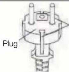
text_image
PlugGrounding tab
(only for UK)
- This appliance is equipped with a cord that has a earthed wire connected to an earthed pin. The plug must be plugged into a socket that is properly installed and earthed. Do not under any circumstances cut or remove the square earthed pin from this plug.
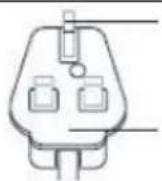
square earthed pin
Plug
Usage cautions
- Ventilate the room periodically during use, especially if using gas appliances in conjunction with the air conditioner.
- Be sure to turn the unit off and disconnect the power supply cord before performing any maintenance or cleaning.
- Do not splash or pour water directly onto the unit. Water can cause electrical shock or equipment damage.
- Drainage should be performed whenever moving the air conditioner (see page 19). If any water remains in the tank, it may spill out while being moved.
-
To ensure proper drainage, the drainage hose must have no kinks and must not be elevated during dehumidification mode. If not, the drained water may spill out into the room.
-
The temperature around the drainage hose must not be below freezing point when used. Drained water may freeze inside the hose, causing water inside the unit to overflow into the room.
- Do not block the exhaust air outlet with obstacles. Cooling performance may be reduced or stop completely.
- Provide a residual current device (ROD) in order to protect against electric shock in accordance with British Standard and Wiring Rules.
- Exposure to direct airflow for an extended period of time could be hazardous to your health. Do not expose occupants, pets, or plants to direct airflow for extended periods of time.
- Do not use this air conditioner for non-specified special purposes (e.g. preserving precision devices, food, pets, plants, and art objects). Usage in such a manner could harm such property.
Notes on operation
- Allow 3 minutes for the compressor to restart cooling.
If you turn the air conditioner off and immediately restart it, allow three minutes for the compressor to restart cooling. There is an electronic device in the unit that keeps the compressor turned off for three minutes for safety. - In the event of a power failure during use, allow 3 minutes before restarting the unit. After power is
reinstated, restart the air conditioner. If the power was off for less than three minutes, be sure to wait at least three minutes before restarting the unit. If you restart the air conditioner within three minutes, a protective device in the unit may cause the compressor to shut off. This protective device will prevent cooling for about 5 minutes. Any previous settings will be cancelled and the unit will return to its initial settings.
- Low temperature operation: Is your unit freezing up? Freezing may occur when the unit is set close to 18 °C in low ambient temperature conditions, especially at night. In these conditions, a further temperature drop may cause the unit to freeze. Setting the unit to a higher temperature will prevent it from freezing.
- Dehumidification mode increases room temperature. The unit generates heat during dehumidification mode and the room temperature will rise. Warm air will be blown out from the Exhaust air outlet, but this is normal and does not indicate a problem with the unit.
- This air conditioner blows the warm air generated by the unit outside the room via the exhaust hose while in cool mode. Accordingly, the same amount of air as that blown out will enter the room from outside through any openings into the room.
UNIT DESCRIPTION
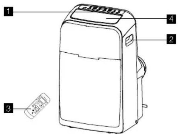
text_image
1 2 3 41 CONTROL PANEL
2 CARRYING HANDLE (BOTH SIDES)
3 REMOTE CONTROL
4 ROOM AIR DISCHARGE
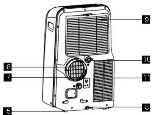
5 CASTOR
6 EXHAUST AIR OUTLET
text_image
Labeled diagram of a portable air conditioner unit with numbered parts for identification7 EXHAUST ADAPTOR A
8 BOTTOM TRAY DRAIN OUTLET
9 AIR INTAKE
10 DEHUMIDIFYING DRAIN OUTLET
11 AIR INTAKE
Fig. 1
ACCESSORIES INCLUDED
PARTS PARTS NAME: QUANTITY:
 | Exhaust hose 1 pc |
| Unit/ Exhaust Adaptor A 1 pc | |
| Window/ Exhaust Adaptor B 1 pc | |
| Window Sliding Kit 1 set | |
| Foam J teal 3 pc | |
| Remote Control 1 pc | |
| Battery(For remote control) 2 pc | |
 | WALL ADAPTOR (FOR PERMANENT DUCT MOUNTING) 1 pc |
| WALL PLUG 4 pc | |
| SCREWS 4 pc | |
 | 1/2" Screw 4 pcs |
| 3/4" Screw 2 pcs | |
| 1/2" Hex Head Cap Screw 2 pcs | |
| Safety Lock 1 pc | |
 | Storage cover (Optional for some model) 1 pc |
Fig. 2
- Check all the accessories are included in the package and please refer to the installation instructions for their usage.
INSTALLATION INSTRUCTIONS
Exhausting hot air window discharge
In the COOLING Mode the appliance must be placed close to a window or opening so that the warm exhaust air can be ducted outside.
First position unit on a flat floor and make sure there's a minimum of 30.5cm clearance around the unit, and is within the vicinity of a single circuit outlet power source.
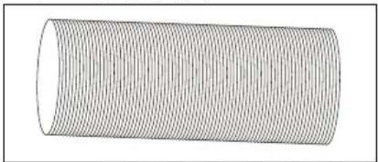
- Take the hose out from the packaging. (Fig.3).
natural_image
3D illustration of a cylindrical object with internal parallel grooves (no text or symbols)Fig. 3
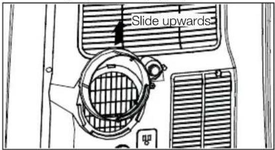
- Remove adaptor A from unit by sliding upwards (Fig.4).
text_image
Slide upwardsFig. 4
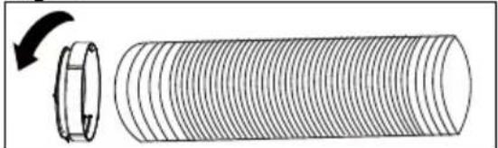
- Extend either side of the hose (Fig. 5) and screw the hose to adaptor A (Fig. 6).

text_image
Extend the side of hoseFig. 5
natural_image
Diagram of a cylindrical pipe with internal grooves and a rotating arrow indicating rotation (no text or symbols)Fig. 6
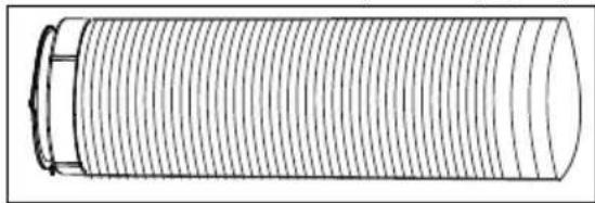
- Extend the other side of the hose and screw it to adaptor B (Fig. 7).
natural_image
Pure technical line drawing of a cylindrical mechanical component with internal grooves (no text or symbols)Fig. 7
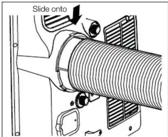
- Slide the assembly onto unit (Fig. 8).
text_image
Slide ontoFig. 8
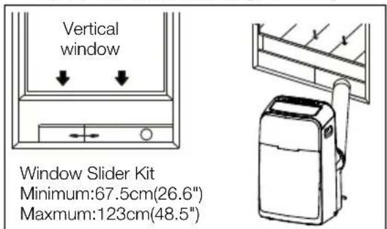
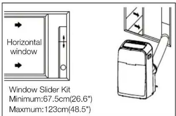
- Affix the adaptor B into the window slider kit and seal. (Fig. 9a&9b)
text_image
Vertical window Window Slider Kit Minimum:67.5cm(26.6") Maximum:123cm(48.5")Fig. 9a
text_image
Horizontal window Window Slider Kit Minimum:67.5cm(26.6") Maximum:123cm(48.5")Fig. 9b
WALL DISCHARGE
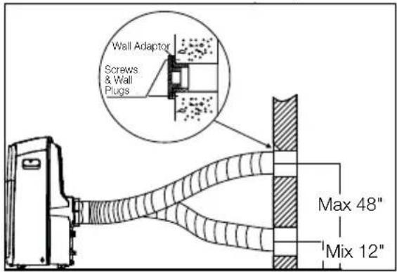
Mount wall adaptor directly over correctly installed duct to outside. (This usually includes aluminum wall ducting & an outside cover. See your hardware specialist for correct installation.) Use wall plugs & screws to secure. (Fig. 10) Attach hose duct to wall adaptor.
text_image
Wall Adaptor Screws & Wall Plugs Max 48" Mix 12"Fig. 10
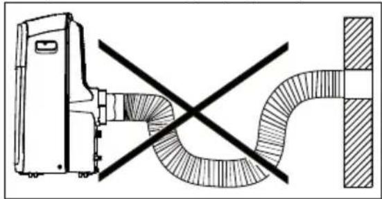
The hose can be extended from its original length of 38.1cm up to 139.7cm, but it is the best to keep the length to minimum required. Also make sure that the hose does not have any sharp bends or sags. (Fig. 11)
natural_image
Technical diagram showing a pipe connection with a crossed-out section and a vertical wall (no text or symbols)Fig. 11
Installation in a double-hung sash window
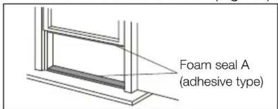
- Cut the foam seals(adhesive type) to the proper lengths and attach them to the window and stool. (Fig. 12)
text_image
Foam seal A (adhesive type)Fig. 12
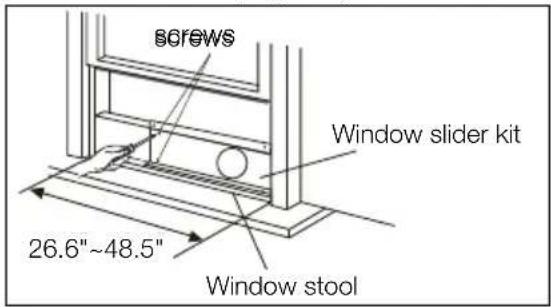
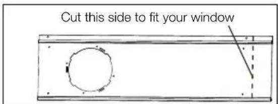
- Open the window sash and place the window slider kit on the window stool (Fig. 13). Attach the window slider kit to the window stool. Adjust the length of the window slider kit according to the width of window. Screw down the two screws on the window slider kit. See Fig.13. Cut the adjustable window slider kit if the width of window is less than 26.6 inches (Fig. 14).
text_image
screws Window slider kit 26.6"~48.5" Window stoolFig. 13
text_image
Cut this side to fit your windowFig. 14
-
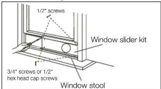
Close the window sash securely against the window slider kit. (Fig. 15)
-
Drive two 1/2" screws to secure the window slider kit to the window sash. (FIG. 15)
-
Secure the window slider kit to the window stool (FIG. 15):
A: For wooden windows: Use 3/4" screws for securing.
B: For Vinyl-Clad windows: Use 1/2" hex head cap screws for securing.
text_image
1/2" screws Window slider kit 3/4" screws or 1/2" hex head cap screws Window stoolFig. 15
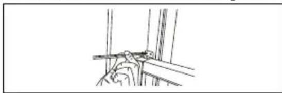
- To secure lower sash in place, attach right angle sash lock with 1/2" (12.7mm) screw as shown (FIG. 16).
NOTE: It is difficult to lock the windows with the sash lock for Vinyl-Clad windows, so you can use lock by window itself.
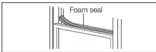
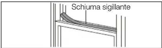
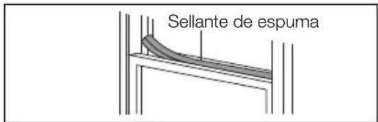
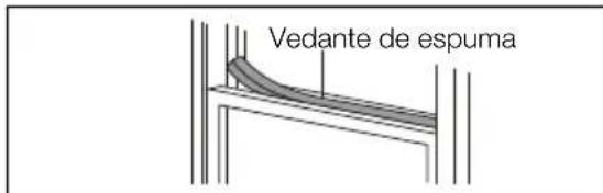
- Cut the foam seal to an appropriate length and seal the open gap between the top window sash and outer window sash, as shown in Fig.17.
natural_image
Line drawing of a mechanical assembly or mounting bracket (no text or symbols)Fig. 16
text_image
Foam sealFig. 17
Installation in a sliding sash window
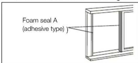
- Cut the foam seals(adhesive type) to the proper lengths and attach them to the window frame. See Fig.18.
text_image
Foam seal A (adhesive type)Fig. 18
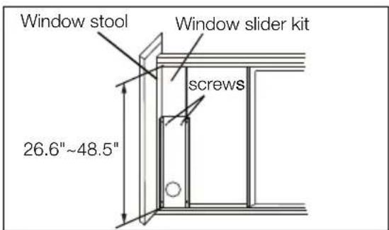
- Open the window sash and place the window slider kit on the window stool. See Fig.19. Attach the window slider kit to the window stool. Adjust the length of the window slider kit according to the height of window. Screw down the two screws on the window slider kit. See Fig.19. Cut the adjustable window slider kit if the height of window is less than 26.6 inches (Fig. 14).
text_image
Window stool Window slider kit screws 26.6"~48.5"Fig. 19
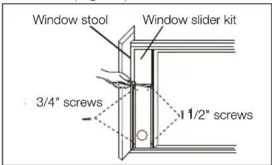
- Close the sliding sash securely against the window slider kit. (Fig. 20)
- Drive two 1/2" screws to secure the window slider kit to the window sash. (Fig. 20)
- Drive two 3/4" screws to secure the window slider kit to the window stool. (Fig. 20)
text_image
Window stool Window slider kit 3/4" screws 1/2" screwsFig. 20
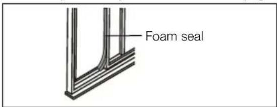
- Cut the foam seal to an appropriate length and seal the open gap between the sliding sash and outer window sash, as shown in Fig.21.
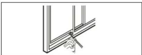
- To secure the sliding sash in place, attach right angle sash lock with 1/2"(12.7mm) screw as shown.(Fig.22)
text_image
Foam sealFig. 21
natural_image
Line drawing of a hand holding a tool near a structural frame (no text or symbols)Fig. 22
AIR CONDITIONER FEATURES
CONTROL PANEL
text_image
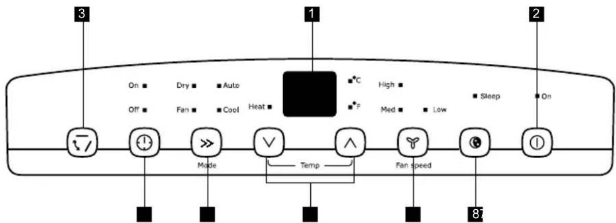
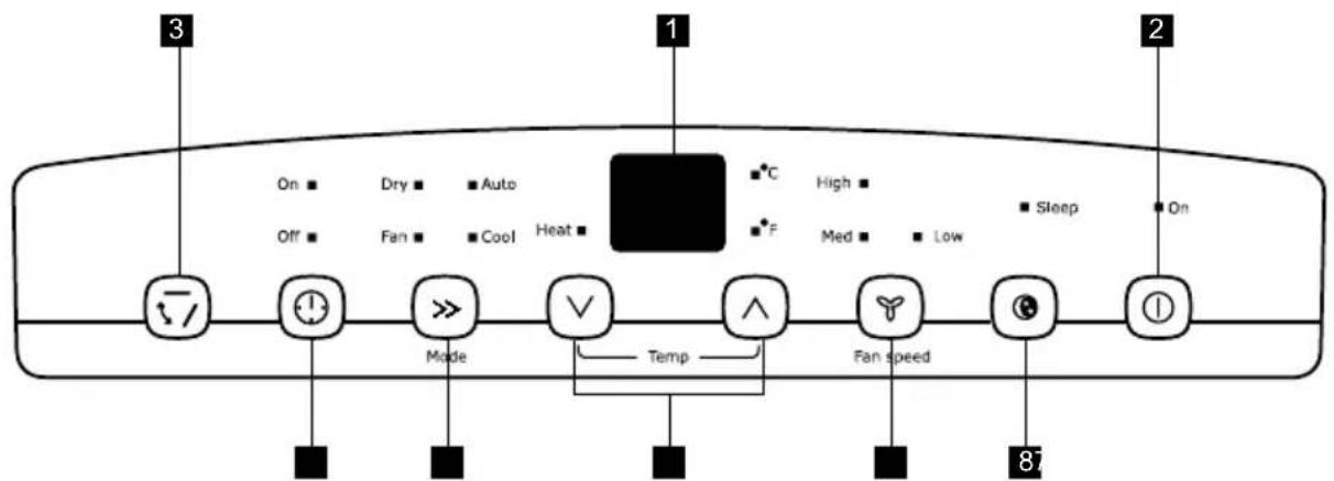
3 1 2 On ■ Dry ■ Auto Off ■ Fan ■ Cool Heat ■ High ■ ■ F High ■ ■ Sleep ■ Low ■ On Mode Temp Fan speed 87Fig. 23
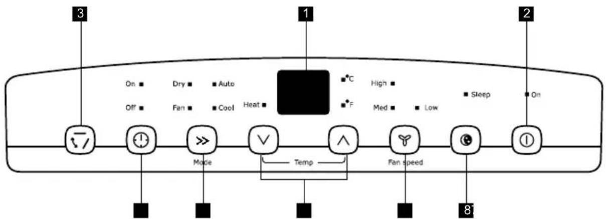
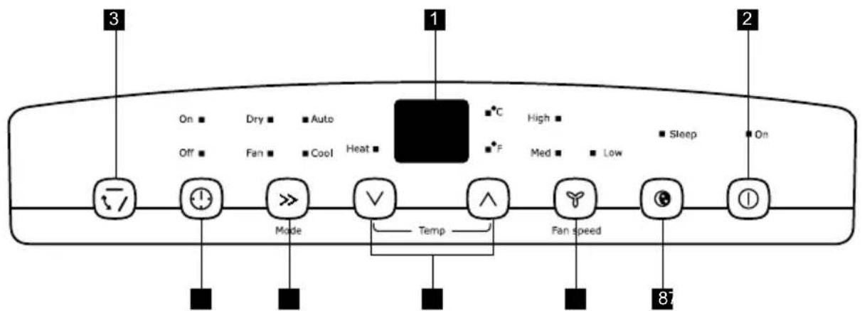
1 DISPLAYS TEMPERATURE/TIME
2 TURNS UNIT ON OR OFF
3 SWING BUTTON
4 ACTIVATES TIMER
5 SETS MODE
6 ADJUSTS TEMPERATURE OR TIME
7 SETS FAN SPEED
8 SLEEP MODE
REMOTE CONTROL
text_image
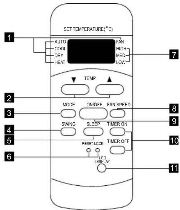
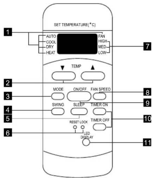
SET TEMPERATURE(°C) AUTO COOL DRY HEAT FAN HIGH MED LOW TEMP MODE ON/OFF FAN SPEED SWING SLEEP TIMER ON RESET LOCK TIMER OFF LED DISPLAY 1 2 3 4 5 6 7 8 9 10 11Fig. 24
1 MODE INDICATION
2 TEMPERATURE/TIMER CONTROL BUTTONS
3 MODE SELECTOR
4 SWING BUTTON
5 SLEEP BUTTON
6 RESET + LOCK PIN BUTTONS
7 FAN SPEED SELECTION
8 FAN SPEED SELECTOR
9 ON/OFF BUTTON
10 TIMER BUTTONS
11 LED DISPLAY BUTTON
Battery Size: AAA

Warning: Do not mix old and new batteries. Do not mix alkaline, standard (carbon-zinc), or rechargeable (nickel-cadmium) batteries.
NOTE
The RESET button is depressed when you want to return to the initial factory settings. The LOCK button is depressed to lock the keypad so the settings cannot be changed. The key symbol will appear in the display of the remote control, depress the LOCK button again to release. Use a small pin to depress these buttons.
OPERATING INSTRUCTIONS
NOTE
The following instructions represent the Control Panel, the same instructions can be used for the Remote Control.
COOLING MODE:
In this mode the exhaust adaptor hose MUST be used.
- Press the MODE button until the "Cool" indicator lights.
- Press the "VΛ" Temp buttons for desired setting.
- Press the FAN button for desired fan speed.
HEATING MODE: (on some models) In this mode the exhaust adaptor hose MUST be used.
- Press the MODE button until the "Heat" indicator lights.
- Press the "VΛ" Temp buttons for the desired heat setting.
- Press the FAN button for desired fan speed.
- Connected drain hose. See drainage section.
DRY MODE:
In this mode you do not need to use the exhaust adaptor hose, BUT the water collected must be discharged. See Drainage Section.
- Press the MODE button until the "Dry" indicator lights.
- The fan will run at low speed and the display will show the room temperature.
- Keep doors & windows closed for best effect.
AUTO MODE:
Always have the exhaust hose attached in this mode.
When you set the air conditioner in AUTO mode, it will automatically select cooling, heating(inapplicable for cooling only models), or fan only operation depending on what temperature you have selected and the room temperature. The air conditioner will control room temperature automatically round the temperature point set by you. Under AUTO mode, you can not select the fan speed.
FAN MODE:
In this mode there is no need to use the exhaust hose or drainage hose. However, if you require stale or smokey air to be removed from the room, hook up the duct accessories as described in the "EXHAUSTING HOT AIR" section.
- Press the MODE button until the "Fan" indicator lights.
- Press the FAN button to choose the desired fan speed.
- The fan will run at the selected speed and the display will show the room temperature.
TIMER OPERATION:
You can set both delay stop and delay start while unit is in ON position or OFF position. When unit is in ON position, first press TIMER button to go to delay stop setting, then "timer off" light will illuminate, tap or hold the UP arrow (V) or the DOWN arrow (A) to change delay stop timer at 0.5 hour increments up to 10 hours, then at 1 hour increments up to 24 hours. Then press the TIMER button to confirm the setting (the control will confirm the setting automatically after 5 seconds) and go to delay start setting. Use the same way as above to set the delay start timing. If you don't need to set delay start, press the TIMER button again to exit. After 5 seconds, the control will automatically change the display back to previous temperature display. If you want to check remaining time, press the TIMER button. The delay start operation automatically selects mode, temperature and fan speed the same as last operation you set.
To activate the Timer function when the unit is in Off mode, press TIMER button to first enter delay start and secondly enter delay stop in the same way as above.
To cancel the timer setting, simply tap (V) or (A) button to change the timing to 0.0.
SLEEP OPERATION:
In this mode the selected temperature will increase by 1 °C 30 minutes after the mode is selected. The temperature will then increase by another 1 °C after an additional 30 minutes. This new temperature will be maintained for 7 hours before it returns to the originally selected temperature. This ends the "Sleep" mode and the unit will continue to operate as originally programmed. The "Sleep" mode program can be cancelled at any time during operation by again pressing the "Sleep" button.
Note: This feature is unavailable under FAN or DRY modes.
SWING OPERATION:
When you turn on the unit, the louver will swing and stop at a certain angle. You can press the SWING button to let the louver swing automatically. Press the SWING button again while you want the louver stop at desired angle.
FAULT CODE:
If the display reads "E1", the room temperature sensor has failed. Call for service.
temp/timer setting
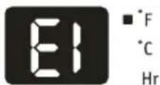
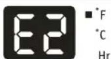
If the display reads "E2", the evaporator temperature sensor has failed. Call for service.
temp/timer setting
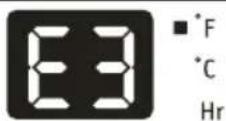
If the display reads "E3", the condenser temperature sensor has failed. Call for Service.
temp/timer setting
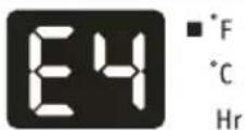
If the display reads "E4", the display panel communication has failed. Call for sen/ice.
temp/timer setting
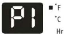
If the display reads "P1", bottom tray is full. Carefully move the unit to a drain location, remove the bottom drain plug and let the water drain away. Restart the machine until the "P1" symbol disappears. If error repeats, call for service.
temp/timer setting
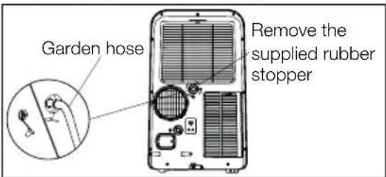
DRAINAGE:
- During the dehumidifying mode, you will need a garden hose (sold separately) to drain the condensate from the unit. Remove the rubber stopper from the hose connector, then screw on a garden hose to the connector as shown on fig 25.
The hose may then:
A. Discharge into a drain that is lower than the unit.
B. Be connected to a condensate pump (sold separately).
text_image
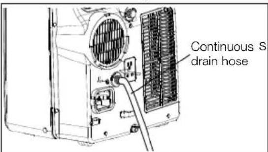
Garden hose Remove the supplied rubber stopper- During the Heating mode, you will need to connect a drain hose to the rear of unit as Fig.26
text_image
Continuous S drain hoseAdditional things you should know Now that you have mastered the operating procedure, here are more features in your control that you should become familiar with.
- The "Cool" circuit has an automatic 3 minute time delayed start if the unit is turned off and on quickly. This prevents overheating of the compressor and possible circuit breaker tripping. The fan will continue to run during this time.
- The control will maintain the set temperature within 1 °C, between 17 °C and 30 °C (62 °F and 86 °F).
- The control is capable of displaying temperature in degrees Fahrenheit or degrees Celsius. To convert from one to the other and back, press and hold the "TEMP" Up (A) and Down (V) buttons together for 3 seconds.
- After a power outage, the unit will memorize the last setting and return the unit to the same setting once power is restored.
CARE & CLEANING
Clean your air conditioner occasionally to keep it looking new. Be sure to unplug the unit before cleaning to prevent shock or fire hazards.
Air Filter Cleaning
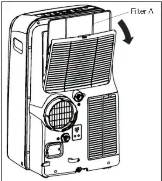
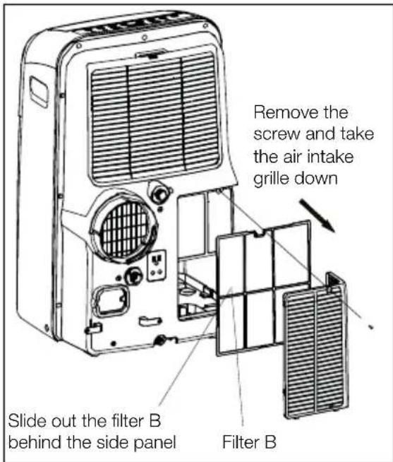
- This unit has two filters, they are filter A and B. Grasp the upper panel tab and take off the filter A which behind the grill of the back panel (Fig. 27). Remove the lower filter B by loosening the screw. Take down the air inlet grille, then remove the air filter as shown in Fig.28.
text_image
Filter AFig. 27
text_image
Remove the screw and take the air intake grille down Slide out the filter B behind the side panel Filter BFig. 28
- Wash the filter using liquid dishwashing detergent and warm water. Rinse filter thoroughly. Gently shake excess water from the filter. Be sure filter is thoroughly dry before replacing. - Or, instead of washing you may vacuum the filter clean.
Cabinet Cleaning
- Be sure to unplug the air conditioner to prevent shock or fire hazard.
The cabinet and front may be dusted with an oil-free cloth or washed with a cloth dampened in a solution of warm water and mild liquid dishwashing detergent. Rinse thoroughly and wipe dry.
- Never use harsh cleaners, wax or polish on the cabinet front.
- Be sure to wring excess water from the cloth before wiping around the controls. Excess water in or around the controls may cause damage to the air conditioner.
BEFORE YOU CALL
Air conditioner will not operate.
- Wall plug disconnected. Push plug firmly into wall outlet.
- Plug Current Device Tripped. Press the RESET button.
- House fuse blown or circuit breaker tripped. Replace fuse with time delay type or reset circuit breaker.
- Control is OFF. Turn Control ON and set to desired setting.
- P1 appears in the display window. Drain water as described in Drainage Section.
- Shut off in Heat mode. When the air outlet exceeds 70 °C (158 °F), the automatic heat protection engages. Romove any blockages and let appliance cool down.
- Room Temperature lower than the set temperature (Cool Mode). Reset the temperature.
- Room Temperature higher than the set temperature (Heat Mode). Reset the temperature.
Air from unit does not feel cold enough.
- Room temperature below 16 °C (60 °F). Cooling may not occur until room temperature rises above 16 °C (60 °F).
- Reset to a lower temperature.
Winter Storage
- If you plan to store the appliance during the winter, cover it with plastic or return it to its carton.
- For the model which with accessory of storage cover, use it directly for the appliance storage.
- Compressor shut-off by changing modes. Wait approximately 3 minutes and listen for compressor to restart when set in the COOL mode.
Air conditioner cooling, but room is too warm - NO ice forming on cooling coil behind decorative front.
- Outdoor temperature below 16 °C (60 °F). To defrost the coil, set FAN ONLY mode.
- Air filter may be dirty. Clean filter. Refer to Care and Cleaning section. To defrost, set to FAN ONLY mode.
- Temperature is set too low for night-time cooling. To defrost the coil, set to FAN ONLY mode. Then, set temperature to a higher setting.
- Exhaust duct not connected or blocked. See EXHAUSTING HOT AIR Section.
Air conditioner cooling, but room is too warm - ice forming on cooling coil behind decorative front
- Dirty air filter - air restricted. Clean air filter. Refer to Care and Cleaning section.
- Temperature is set too high. Set temperature to a lower setting.
-
Air directional louvers positioned improperly. Position louvers for better air distribution.
-
Front of unit is blocked by drapes, blinds, furniture, etc. - restricts air distribution. Clear blockage in front of unit.
- Doors, windows, registers, etc. open - cool air escapes. Close doors, windows, registers, etc.
- Unit recently turned on in hot room. Allow additional time to remove "stored heat" from walls, ceiling, floor and furniture.
Air conditioner turns on and off rapidly.
- Dirty air filter - air restricted. Clean air filter.
- Outside temperature extremely hot. Set FAN speed to a faster setting to bring air through cooling coils more frequently.
Noise when unit is cooling.
- Air movement sound. This is normal. If too loud, set to lower FAN setting.
- Vibration from uneven floor. Move or support appliance correctly on even surface.
Room too cold.
- Set temperature too low. Increase set temperature.
Room Too Hot.
- Set temperature too high. Lower setting.
ENVIRONMENT CONCERNS
Information on disposal for users
- If you wish to discard this product, please contact your local authorities and ask for the correct method of disposal.
- This air conditioner uses R41 OA refrigerant.

The battery supplied with this product contains traces of Lead.
For EU: The crossed-out wheeled bin implies that used batteries should not be put to the general household waste! There is a separate collection system for used batteries, to allow proper treatment and recycling in accordance with legislation. Please contact your local authority for details on the collection and recycling schemes.
For Switzerland: The used battery is to be returned to the selling point. For other non-EU countries:
Please contact your local authority for correct method of disposal of the used battery.
- Battery, including those which is heavy metal-free, should not be disposed of with household waste. Please dispose of used battery in an environmentally sound manner. Find out about the legal regulations which apply in your area.
SOMMAIRE
text_image
Labeled diagram of a portable air conditioner unit with numbered parts for identification7 ADAPTATEUR D'ÉCHAPPEMENT A
8 SORTIE DE VIDANGE DU BAC INFÉRIEUR
9 ARRIVÉE D'AIR
10 SORTIE DE VIDANGE DE DÉSHUMIDIFICATION
11 ARRIVÉE D'AIR
Fig. 1
ACCESSOIRES INCLUS
natural_image
3D illustration of a cylindrical object with horizontal lines, no text or symbols presentFig. 3
natural_image
Diagram of a cylindrical pipe with internal grooves and a rotating arrow indicating rotation (no text or symbols)Fig. 6
natural_image
Technical line drawing of a cylindrical mechanical component with internal grooves (no text or symbols)Fig. 7
natural_image
Diagram showing a pipe connection with a crossed black line indicating no crossing or disconnection (no text or symbols present)Fig. 11
natural_image
Line drawing of a mechanical assembly or bracket with no visible text or symbolsFig. 16
text_image
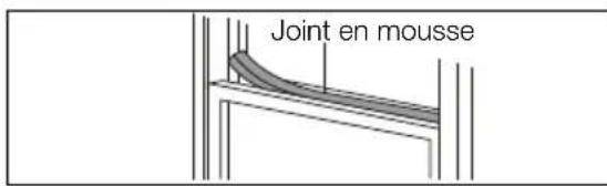
Joint en mousseFig. 17
natural_image
Technical line drawing of a window frame with a handle and clasp (no text or symbols)Fig. 22
CARACTÉRISTIQUES DU CLIMATISEUR
BANDEAU DE COMMANDE
text_image
3 1 2 On ■ Dry ■ Auto Off ■ Fan ■ Cool Heat ■ High ■ °F ■ Med ■ Low Sleep On Made Temp Fan speed 87Fig. 23
1 AFFICHAGE DE LA
TEMPÉRATURE/HEURE
2 ALLUME OU ÉTEINT L'APPAREIL
3 TOUCHE SWING
4 ACTIVE LE MINUTEUR
5 SÉLECTIONNE LE MODE
TÉLÉCOMMANDE
text_image
SET TEMPERATURE(°C) AUTO COOL DRY HEAT FAN HIGH MED LOW TEMP MODE ON/OFF FAN SPEED SWING SLEEP TIMER ON RESET LOCK TIMER OFF LED DISPLAY 1 2 3 4 5 6 7 8 9 10 11Fig. 24
1 INDICATION DU MODE
2 TOUCHES TEMPÉRATURE/HEURE
3 SÉLECTEUR DE MODE
4 TOUCHE SWING
5 TOUCHE SLEEP
6 RÈGLE LA TEMPÉRATURE OU L'HEURE
7 RÈGLE LA VITESSE DU VENTILATEUR
8 MODE SLEEP
6 TOUCHES RESET + LOCK PIN
7 RÉGLAGE DE VITESSE DU VENTILATEUR
8 SÉLECTEUR DE VITESSE DU VENTILATEUR
9 TOUCHE ON/OFF
10 TOUCHES DU MINUTEUR
11 TOUCHE DE L'AFFICHAGE LED
Piles : AAA

FONCTIONNEMENT SWING (basculement) :
www.electrolux.com/productregistration

text_image
Labeled diagram of a portable air conditioner unit with numbered parts for identification7 ADATTATORE A DI ESPULSIONE DELL'ARIA
8 TAPPO DI SCARICO
9 PRESA D'ENTRATA DELL'ARIA (ESTERNA)
10 SCARICO DI DRENAGGIO
DEUMIDIFICAZIONE
11 PRESA D'ENTRATA DELL'ARIA (ESTERNA)
Fig. 1
ACCESSORI FORNITI
natural_image
3D rendering of a cylindrical object with internal parallel grooves (no text or symbols)Fig. 3
natural_image
Diagram of a cylindrical pipe with internal grooves and a rotating arrow indicating rotation (no text or symbols)Fig. 6
natural_image
Technical line drawing of a cylindrical mechanical component with internal grooves (no text or symbols)Fig. 7
text_image
InfiltrareFig. 8
natural_image
Diagram showing a mechanical device connected to a curved pipe with a diagonal line crossing through it (no text or symbols present)Fig. 11
natural_image
Line drawing of a hand holding a tool near a vertical structure (no text or symbols)Fig. 16
text_image
Schiuma sigillanteFig. 17
natural_image
Line drawing of a window frame with a hand holding a tool near the bottom (no text or symbols)Fig. 22
CARATTERISTICHE DEL CONDIZIONATORE D'ARIA
QUADRO COMANDI
text_image
3 1 2 On ■ Dry ■ Auto Off ■ Fan ■ Cool Heat ■ High ■ F ● High ■ ● Low ■ Sleep ● On Mode Temp Fan speed 8'Fig. 23
text_image
Labeled diagram of a portable air conditioner unit with numbered parts for identificationnatural_image
3D illustration of a cylindrical object with internal parallel grooves (no text or symbols)Fig. 3
natural_image
Diagram of a cylindrical pipe with internal grooves and a rotating arrow indicating rotation (no text or symbols)Fig. 6
natural_image
Pure technical line drawing of a cylindrical mechanical component with internal grooves (no text or symbols)Fig. 7
natural_image
Diagram showing a pipe connection with a crossed black line indicating no crossing, alongside a shaded rectangular area (no text or symbols)Fig. 11
natural_image
Simple line drawing of a person using a tool on a mechanical structure (no text or symbols)Fig. 16
text_image
Sellante de espumaFig. 17
natural_image
Technical line drawing of a structural joint or bracket with a hand holding a tool (no text or symbols present)Fig. 22
CARACTERÍSTICAS DEL ACONDICIONADOR DE AIRE
PANEL DE CONTROL
text_image
3 1 2 On ■ Dry ■ Auto Off ■ Fan ■ Cool Heat ■ High ■ °F ■ Med ■ Low Sleep On Made Temp Fan speed 87Fig. 23
www.electrolux.com/productregistration

text_image
Labeled diagram of a portable air conditioner unit with numbered parts for identificationnatural_image
3D rendering of a cylindrical object with internal parallel grooves (no text or symbols)Fig. 3
natural_image
Diagram of a cylindrical pipe with internal grooves and a rotating arrow indicating rotation (no text or symbols)Fig. 6
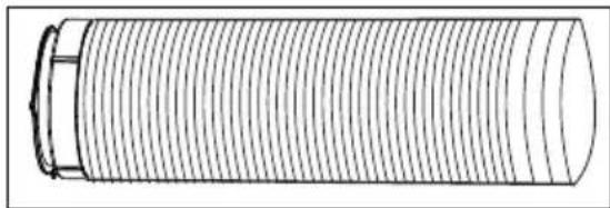
- Estique o outro lado do tubo e enrosque-o no adaptador B (Fig. 7).
natural_image
Pure technical line drawing of a cylindrical mechanical component with internal grooves (no text or symbols)Fig. 7
natural_image
Diagram showing a pipe connection with a crossed black line indicating no crossing, alongside a shaded rectangular area (no text or symbols)Fig. 11
natural_image
Line drawing of a mechanical assembly or tool with no visible text or symbolsFig. 16
text_image
Vedante de espumaFig. 17
natural_image
Technical line drawing of a structural joint or bracket (no text or symbols)Fig. 22