
Lira - Heating FERROLI - Free user manual and instructions
Find the device manual for free Lira FERROLI in PDF.
| Product type | Pellet stove (heating) |
| Brand | Ferroli |
| Model | Lira |
| Fuel | Wood pellets (DIN plus 51731 / UNI CEN/TS 14961 / Ö-Norm M 7135) |
| Rated thermal output | 6,58 kW |
| Reduced thermal output | 2,3 kW |
| Nominal efficiency | 91,51 % |
| Reduced efficiency | 92,2 % |
| Nominal hourly consumption | 1,483 kg/h |
| Reduced hourly consumption | 0,52 kg/h |
| Hopper capacity | 21 liters (~15 kg) |
| Max heating volume | 145 m³ |
| Flue gas outlet diameter | 80 mm |
| Air intake diameter | 50 mm |
| Minimum draft | 10 Pa |
| Power supply | 230 V / 50 Hz |
| Max power consumption (ignition) | 420 W |
| Power consumption (normal operation) | 120 W |
| Weight | 65 kg |
| Dimensions (H x W x D) | 936 x 440 x 509 mm |
| Safety distances (rear / right side / left side) | 200 mm / 300 mm / 0 mm |
| CO emissions at 13% O₂ | 0,02 % (nominal and reduced) |
| Flue gas temperature (nominal / reduced) | 152,6 °C / 84 °C |
| Functions | Weekly programming, remote control, standby mode, ECO mode, audible alarms |
| Cleaning | Daily brazier, ash pan every 2-3 days, glass and slots, annual professional maintenance |
| Safety | Safety thermostat (85°C), vacuum switch, overvoltage protection (fuse 2A), shutdown in case of power failure |
Frequently Asked Questions - Lira FERROLI
User questions about Lira FERROLI
0 question about this device. Answer the ones you know or ask your own.
Ask a new question about this device
Download the instructions for your Heating in PDF format for free! Find your manual Lira - FERROLI and take your electronic device back in hand. On this page are published all the documents necessary for the use of your device. Lira by FERROLI.
USER MANUAL Lira FERROLI
48421A620-M5_01/13 Hardware - M
Read the instructions carefully before installation, use and maintenance.
The manual is an integral part of the unit.
COLA guarantees its products, except for parts subject to normal wear, in accordance with the current regulations. For the warranty terms, please contact the importer or the authorised agent who can integrate the compulsory warranty period with an additional period under his sole and exclusive responsibility.
The product warranty is invalidated for any trouble, breakage or accident due to failure to comply with or apply the instructions provided in this manual.
FR 48-69
CE MARKING INFORMATION
1.10. Instructions for requesting assistance and replacement parts
2. TRANSPORT AND INSTALLATION
2.1. Packing, handling, shipment and transport
2.2. Place of installation, positioning and fire-prevention safety
2.3. Air inlet
2.4. Fume exhaust
2.4.1. Types of installation
2.5. Brazier and baffle position check
2.6. Electrical connection
2.7. Wiring diagram
2.8. Emergency
3. STOVE SAFETY
3.1. Safety distance from flammable materials
3.2. Fume exhaust safety
3.3. Combustion chamber overpressure safety
3.4. Overheating - pellet hopper temperature safety thermostat
3.5. Safety against flare-back in the pellet chute
3.6. Overcurrent electrical protection device
3.7. Power failure safety
3.8.Fume fan failure
4. STOVE USE
4.1. Introduction
4.2. Control panel
4.3. Lighting
4.4. Work
4.5.Shutdown
4.6. Menu
4.6.1 menu 01 - adjust fans
4.6.2 menu 02 - set clock
4.6.3 menu 03 - enable chrono
4.6.4 menu 04 - select language
4.6.5 menu 05 - standby mode
4.6.6 menu 06 - buzzer
4.6.7 menu 07 - initial loading
4.6.8 menu 08 - stove status
4.6.9 menu 09 - settings by technician
4.6.10 menu 10 - installer settings
4.6.11 menu 11 - ECO mode
4.7Remote control
4.7.1 replacing the battery
4.8 External thermostat
4.9 Idle period (end of season)
5 STOVE CLEANING
5.1 Cleaning the brazier
5.2 Cleaning the ash container
5.3 Cleaning the glass and air slots
5.4 Cleaning the fume extractor and combustion chamber
5.5 Cleaning the air flow meter
5.6 Cleaning the ceramic surfaces (ceramic models)
5.7 Cleaning the flue - flue connection
6 MAINTENANCE
6.1 Introduction
6.2 Removing the cladding
6.3 Stove internal parts
6.4 Electrical components
7 TROUBLESHOOTING
7.1 Alarm management
8 ENCLOSURES
8.1 CE marking information
1 GENERAL INFORMATION
1.1 Introduction
Dear Customer,
First of all we wish to thank you for the trust placed in us by purchasing one of our products. Please read and carefully follow the advice given in this installation, use and maintenance manual in order make best use of the product.
1.2 Using the manual
The Manufacturer reserves the right to make technical or aesthetic changes to the products at any time without notice.
Stove installation, use and maintenance operations must comply with the requirements given in this manual as well as the European, National, Regional, Provincial and Municipal regulations.
The drawings, measurements, diagrams and any other configurations are given only by way of example.
This manual is an integral part of the product; make sure it always stays with the stove, even if sold, transferred to another owner or installed in another place, so that it can be consulted at any time.
If lost or damaged, ask the Authorised Service Centre for a copy so that the stove always has its own manual.

This symbol indicates the presence of an important message; failure to pay attention to it can result in serious damage to the stove and even injury
Pay special attention to "words in bold face"
1.3 Safety rules.
- Read the use and maintenance manual before installing, lighting and servicing the stove.
- Installation, the electrical connection, testing and maintenance must be carried out by a qualified and/or authorised technician.
- Connect the stove to an approved flue by means of an inspectionable terminal; several units can be connected only if allowed by the local regulations and by the flue inspection Body.
- Connect the stove to the suction system by means of a pipe or air inlet from outside.
- Connect the stove to an approved 230V - 50Hz electrical socket.
- Make sure the electrical system and the sockets are suitable for the maximum absorption of the unit, specified on the label and in this manual.
- The stove must be unplugged and cold before carrying out any maintenance.
- Do not use flammable liquids or substances to light the stove or rekindle the flame: when the stove is lit, pellet ignition is automatic.
- The pellet stove must only be fed with wood pellets having the characteristics described in this manual.
- The stove must not be used as an incinerator.
- Never block the combustion air inlet and fume outlet openings.
- Do not handle easily flammable or explosive substances near the stove while it is operating.
- Do not remove or modify the pellet hopper protection grille or the safety devices.
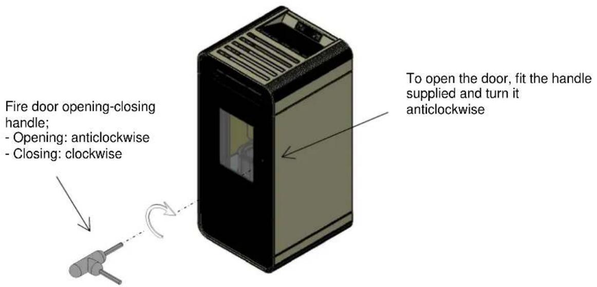
- Do not operate the stove with the fire door open and/or the glass damaged or broken.
- During operation the intense heat generated by combustion of the pellets makes the external surfaces of the stove very hot, and in particular the fire door, handle and flue pipe. Therefore avoid contact with these parts without suitable protection.
- Keep objects that are flammable and/or not heat resistant at a suitably safe distance.
- Clean the brazier regularly every time the stove is lit or whenever reloading pellets.
- Have the duct and smoke baffles inside the combustion chamber cleaned regularly by qualified personnel.
- Avoid the creation of smoke and unburnt products during lighting and/or normal operation; an excessive accumulation of unburnt pellets in the brazier must be eliminated manually before carrying out relighting.
- Warn children and guests about the hazards described above.
In case of operating problems, the stove can be relit only after eliminating the cause of the problem. - Any tampering and/or unauthorized replacements with non-original parts of the stove can create a risk for the user's safety and relieves the manufacturer of any civil or penal liability.
- Only use original replacement parts recommended by the manufacturer.

The manufacturer declines any liability for problems, damage or accidents caused by failure to follow or apply the instructions contained in this manual.
1.4 Technical description
The stove works exclusively on pellets, providing healthy and safe heat in the room. The stove's automatic control systems guarantee optimum heat output and complete combustion; there are also safety systems to guarantee safe operation for the stove parts and for the user.
When correctly installed, the unit works in any outside climatic conditions, and in any case in critical conditions (strong wind, frost, etc.) the safety systems can cut in, shutting down the stove.
| Structure steel and cast iron | ||
| Combustion chamber steel and cast iron | ||
| Heating input max - reduced | Nom. input 7.19 kW | Red. output 2.5 kW |
| Heat output nominal - reduced | Nom. output 6.51 kW | Red. output 2.3 kW |
| Hourly consumption Nom. output- Red. output | Nom. output 1.483 kg./h* | Red. output 0.52 kg./h.* |
| Efficiency Nom. output- Red. output | Nom. output 91.51 % | Red. output 92.2 % |
| Fume outlet temperature Nom. output- Red. output Nom. | output 152.6°C | Red. output 84°C |
| CO emissions at 13% O2 | Nom. output 0.02 % Red. output 0.02 % | |
| Flue gas flow Nom. output 4.2 g/s Red. output 3 g/s | ||
| Dust emissions | Nom. output 19.5 mg/m3 | Red. output - mg/m3 |
| Flue draught | 10-14 Pa | |
| Fume outlet pipe | Ø 80 mm | |
| Air inlet pipe | Ø 50 mm | |
| Electrical power supply | 230V/50 Hz | |
| Electrical power input | 420 W max. in lighting stage 120 W for normal operation | |
| Min. safety distance rear - right/left side - floor | 200 - 300 - 0 mm | |
| Dimensions (mm) | H x W x D = 936 x440 x509 mm | |
| Stove weight | 65 kg | |
| Hopper capacity | 21 litres (~15 kg) | |
| Max. heatable volume | 145 m3** | |
- Pellet consumption can vary according to the type of pellets used and their preservation.
** Considering 35 W/h per m3. The building's energy requirement can vary according to the insulation, type and climatic zone.
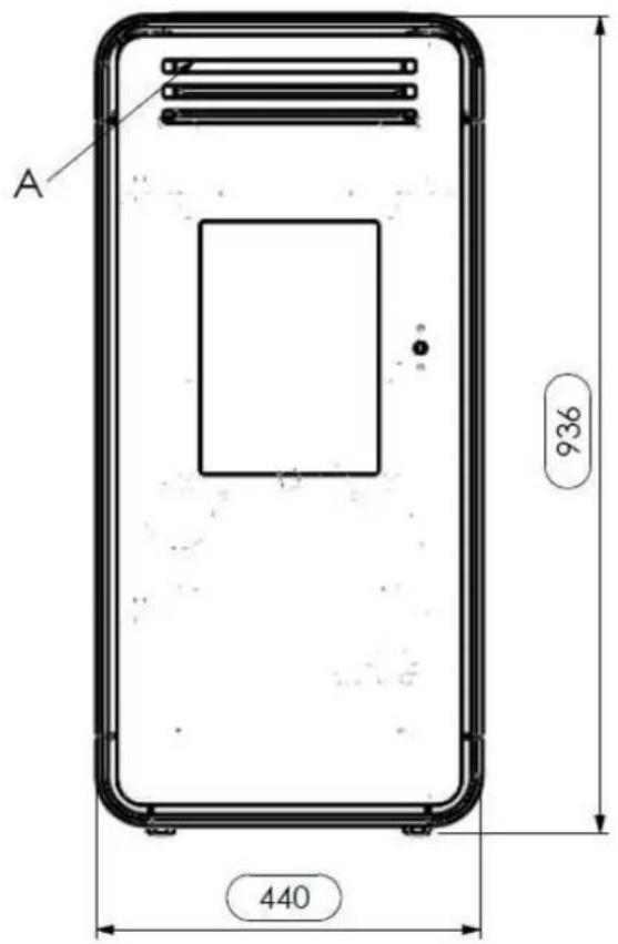
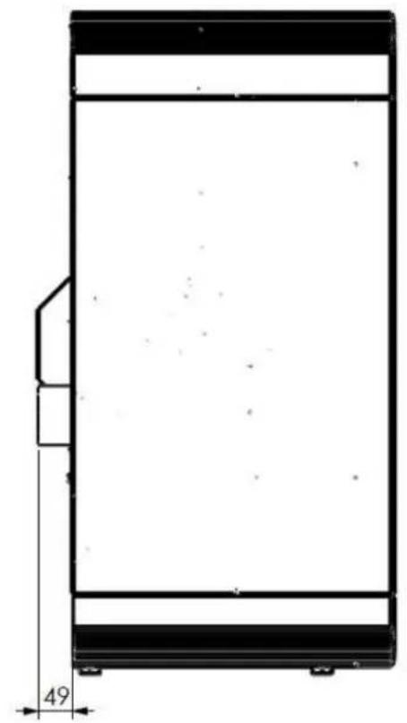
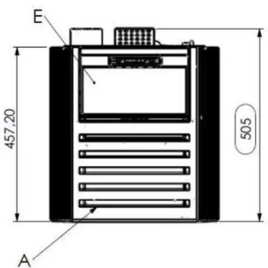
LIRA pellet stove dimensions
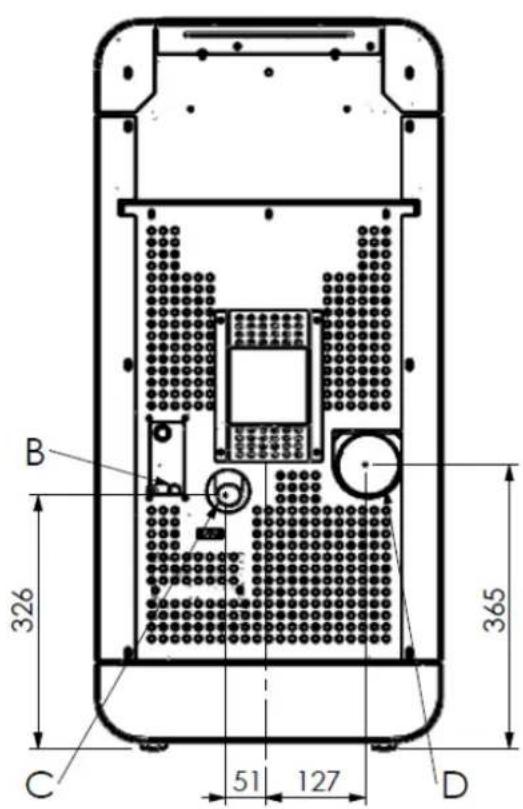
Key:
A - Air grilles
B - Power cable connection
C - Combustion air inlet diam. 50 mm
D - Flue pipe connection diam. 80 mm
E-Pellet hopper door
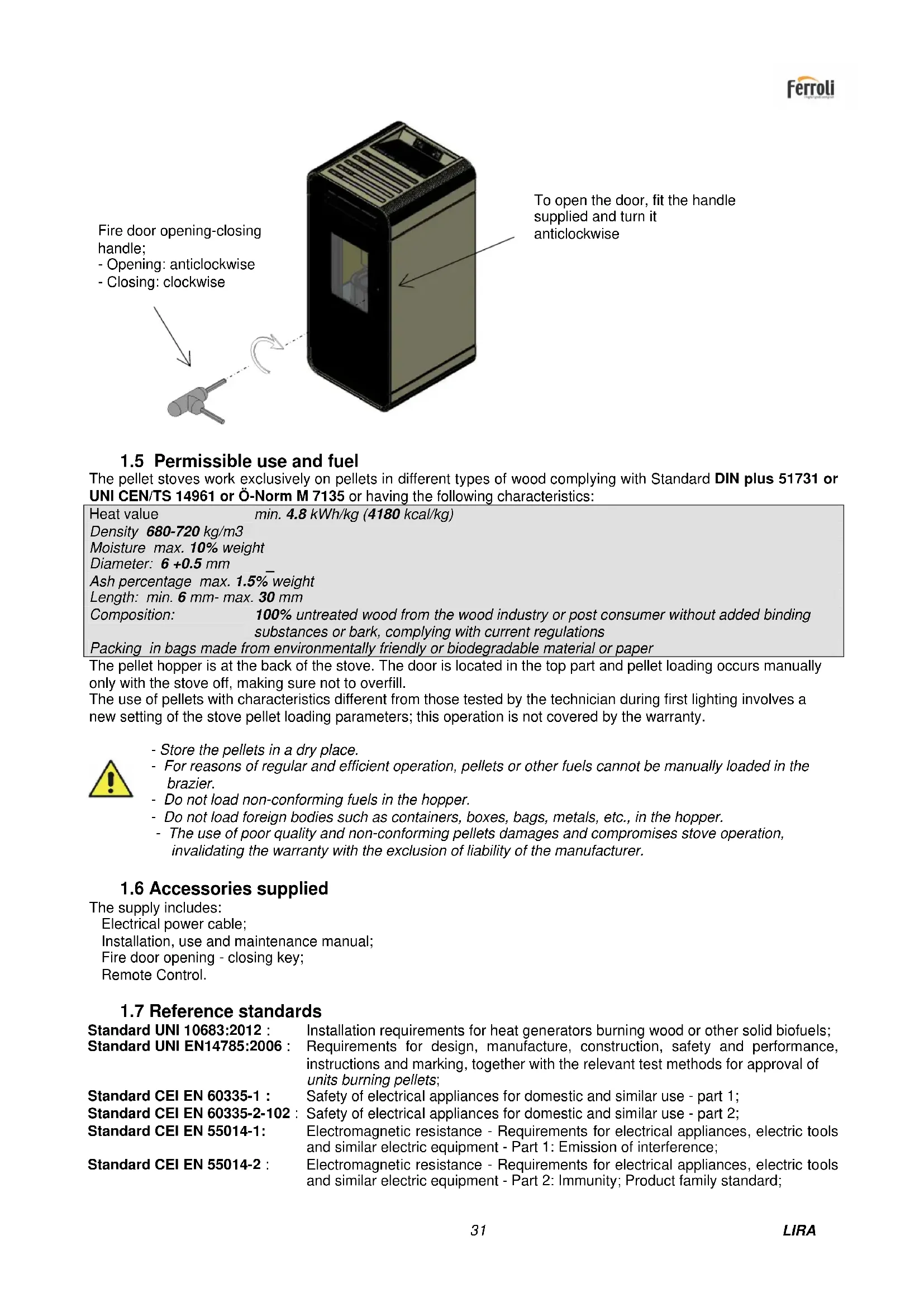
1.5 Permissible use and fuel
The pellet stoves work exclusively on pellets in different types of wood complying with Standard DIN plus 51731 or UNI CEN/TS 14961 or Ö-Norm M 7135 or having the following characteristics:
| Heat value | min. 4.8 kWh/kg (4180 kcal/kg) |
| Density 680-720 kg/m3 | |
| Moisture max. 10% weight | |
| Diameter: 6 +0.5 mm | |
| Ash percentage max. 1.5% weight | |
| Length: min. 6 mm- max. 30 mm | |
| Composition: | 100% untreated wood from the wood industry or post consumer without added binding substances or bark, complying with current regulations |
| Packing in bags made from environmentally friendly or biodegradable material or paper | |
The pellet hopper is at the back of the stove. The door is located in the top part and pellet loading occurs manually only with the stove off, making sure not to overfill. The use of pellets with characteristics different from those tested by the technician during first lighting involves a new setting of the stove pellet loading parameters; this operation is not covered by the warranty.

- Store the pellets in a dry place.
- For reasons of regular and efficient operation, pellets or other fuels cannot be manually loaded in the brazier.
- Do not load non-conforming fuels in the hopper.
- Do not load foreign bodies such as containers, boxes, bags, metals, etc., in the hopper.
- The use of poor quality and non-conforming pellets damages and compromises stove operation, invalidating the warranty with the exclusion of liability of the manufacturer.
1.6 Accessories supplied
The supply includes:
Electrical power cable;
Installation, use and maintenance manual;
Fire door opening - closing key;
Remote Control.
1.7 Reference standards
Standard UNI 10683:2012 :
Standard UNI EN14785:2006 :
Installation requirements for heat generators burning wood or other solid biofuels; Requirements for design, manufacture, construction, safety and performance, instructions and marking, together with the relevant test methods for approval of units burning pellets;
Safety of electrical appliances for domestic and similar use - part 1;
Safety of electrical appliances for domestic and similar use - part 2;
Standard CEI EN 55014-2:
Electromagnetic resistance - Requirements for electrical appliances, electric tools and similar electric equipment - Part 1: Emission of interference;
Electromagnetic resistance - Requirements for electrical appliances, electric tools and similar electric equipment - Part 2: Immunity; Product family standard;
Standard CEI EN 61000-3-2: Limits for harmonic current emissions (Input current ≤ 16 A per phase);
Standard CEI EN 61000-3-3: Limitation of voltage fluctuations and flicker in low voltage supply systems for equipment with nominal current ≤ 16A
Standard CEI EN 62233 : Measuring methods for electromagnetic fields of electrical household appliances and similar with reference to human exposure.
Standards DIN plus 51731 - UNI CEN/TS 14961 - Ö-Norm M 7135 : Standards regarding the specifications and classification of pellets.
1.8 Dataplate
The dataplate is visible on the inside of the pellet hopper door or on the back of the stove. It gives the following data:
Model
Serial number
Type of fuel
Nominal and reduced heat output
Consumption at nominal output and reduced output
Fume temperature at nominal output and reduced output
Thermal efficiency
Power supply voltage
Electrical power input
Flue pipe size
Inlet pipe size
Fluedraught
Stove external dimensions
Safety distance from flammable materials
Weight
1.9 Stove decommissioning
When definitively deciding to not to use the stove any more, we recommend to disconnect the power supply and to empty the pallet tank completely. In order to eliminate the stove, it is necessary to packaged it with a strong packaging and then take contact with local organisation which follows the selling off operations respecting the local rules. Otherwise we recommend to back the stove directly to the distributor when buying a similar new one.
1.10 Instructions for requesting assistance and replacement parts
To request any assistance and/or replacement parts contact your dealer, area importer or the nearest authorised service centre, clearly specifying the following: stove model, serial number, date of purchase, list of replacement parts, details of faults or malfunctioning.

- All operations on components must be carried out by authorised and/or qualified personnel.
- Make sure all electrical connections are disconnected and that the stove is cold before any work on it.
- Only use original replacement parts.
2 TRANSPORT AND INSTALLATION
2.1 Packing, handling, shipment and transport
The stove complete with packing can be lifted using a lift truck, inserting the forks (of suitable length) in the special spaces in the wooden pallet. Make sure the equipment used for lifting and transport can take the weight of the stove, specified on the dataplate and in this manual.
Avoid taking the load in areas where it could be a danger if dropped.
Open the packing, remove the stove from the pallet and position it in the required place, making sure it complies with that provided for. Set the stove down on the floor carefully without bumping and position it in the required place. Make sure the floor can take the weight of the stove, otherwise consult a specialised technician.
Disposal or recycling of the packing must be carried out by the end-user in compliance with the current local regulations.
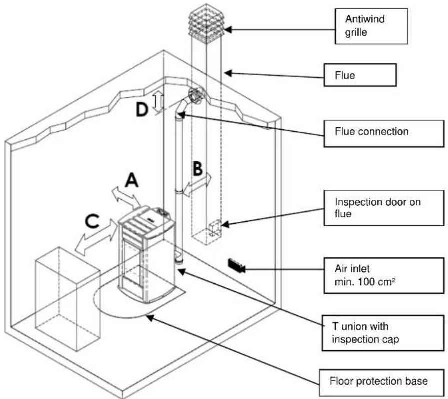
2.2 Place of installation, positioning and fire-prevention safety
The place of installation must be sufficiently ventilated to allow the removal of any combustion smoke leaks.
The unit is suitable for operation in domestic environments with min. temperature not below 0^
To prevent the risk of fire, the structures surrounding the stove must be protected from the heat.
Floors in wood or in any flammable material must be suitably protected at the base with steel or toughened glass panels; the protection must cover the base and also a certain area in front of the stove.
Any wooden boards or beams above or crossed by the flue must be suitably protected in conformity with the requirements of the specific current installation standards.
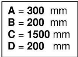
The minimum front distance for the protection of flammable objects is 1.5m . The minimum safety distances from flammable materials must comply with the following table:
Every installation must provide for an easily accessible technical space for periodical maintenance.
The stove is provided with 4 adjustable feet to facilitate positioning on not perfectly flat floors. To adjust the height, tilt the stove slightly and turn the feet as required.
The stove is supplied with the ambient sensor fixed through a wrapper on the back of the stove; we recommend to remove the wrapper and to locate the sensor in the best position possible as to improve the temperature registration in accordance with the ambient context and the length of the cable.
As for temperature registration done at a certain distance we reccomend to install the ambient thermostat/ambient programming clock-thermostat - see. par.4.8.

- The stove cannot be installed in bedrooms, bathrooms and in general in rooms where another heating unit is already installed without an independent air inflow.
- With wooden floors, install a floor protection base in conformity with the current regulations.
- Suitable fire-prevention devices should be arranged for any eventuality.
- Do not install the stove in places with an explosive atmosphere.
2.3 Air inlet
The stove air inlet pipe or intake is located at the back and is round and 50~mm in diameter.
A quantity of air at least equal to that necessary for combustion must flow in the room where the stove is installed; therefore the combustion air necessary to ensure correct operation of the stove must be drawn:
from the room, provided there is a wall air inlet near the stove, communicating with the outside and of minimum area 100cm^2 suitably protected externally by a grille;
or with direct connection to the outside with an appropriate pipe having a minimum internal diameter of 50mm and maximum length of 1.5m , provided with antiwind protection at the end (down bend).
The air inflow can also be obtained from a room adjoining that of installation, provided the flow can occur freely through permanent openings to the outside; the room must not be used as a garage, for storing combustible materials or for activities with fire risk.
2.4 Fume exhaust
The fumes can be exhausted through a connection to a conventional flue or an external duct with double wall or insulated pipe.
The fume exhaust connections must guarantee a minimum draught of 10 Pa so that the evacuation of fumes is assured in case of a temporary power failure.

- The installer must check the efficiency and state of the flue and its conformity with the local, national and European regulations.
- Certified pipes and connections with adequate seals guaranteeing their tightness must be used.
- In case of fire, shut down the stove, promptly call the fire department, and avoid continual attempts to extinguish it.
- Clean the flue and respective connection at least once a year.
2.4.1 Types of installation
Listed below are definitions and requirements for correct installation of an exhaust flue in accordance with Italian Standard UNI10683:
FLUE: a vertical duct for collecting and expelling, at an appropriate height from ground, the fumes coming from a single unit and, where permitted, more than than one.
FLUE technical requirements: it must be fumetight, isolated and insulated depending on its use;
- it must have a mainly vertical path with axis deviation < 45^
- it must be at a suitable distance from flammable materials with insulation or air gap;
- it must preferably have a constant, free and independent round internal section;
- it is advisable for the flue to have an inspectionable chamber for the collection of solid materials
- and any condensate, placed under the beginning of the fume duct.
FLUE CONNECTION or DUCT: duct or connection element between the unit and flue for evacuation of fumes.
DUCT technical requirements: - it must not cross rooms in which the installation of combustion units is not allowed;
- flexible metal tubes or fibre cement pipes are prohibited;
- the use of counter-sloping elements is prohibited;
- horizontal sections must have an upward slope of at least 3^
- the length of the horizontal section must be minimal and not more than 3m
- there must not be more than 3 changes of direction, without the T union;
- with change of direction >90^ a max. of 2 bends can be used with length in horizontal projection not exceeding 2m .
- the fume duct must have a constant section and allow the recovery of soot.
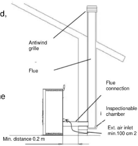
CHIMNEY CAP : a device placed on the top of the flue to facilitate the dispersion of fumes into the atmosphere.
CHIMNEY CAP technical requirements : it must have a section equivalent to that of the flue;
- it must have a useful section not less than double the internal section of the flue;
- it must prevent the entry of rain and foreign bodies and ensure the discharge of fumes in any atmospheric condition;
- it must ensure an adequate dilution of fumes and be positioned outside the backflow area;
- it must be without mechanical means of suction.

The direct discharge of fumes must take place on the roof and not towards closed spaces (even open air).
2.5 Brazier and baffle position check
Before lighting the stove make sure the brazier is in the correct position, i.e. fitted in the special slots. Also make sure the top smoke baffle is properly fitted. A wrongly positioned baffle can result in malfunctioning and excessive blackening of the glass.

At every stove lighting, check the correct position of the brazier on the brazier holder.
2.6 Electrical connection
Connect one end of the power cable to the rear socket of the stove, and the other to the wall socket.
The voltage supplied by the system must match that specified on the stove dataplate and in the technical data section of this manual.
During stove idle periods it is advisable to remove the power cable.

- Make sure the electrical system is equipped with an earth and differential switch in accordance with the current Regulations.
- The power cable must never touch the stove exhaust pipe.
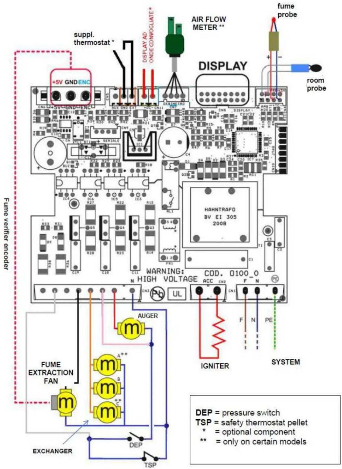
2.7 Wiring diagram
2.8 Emergency
Suitable fire-prevention devices should be arranged for any eventuality.
In case of a fire, proceed as follows:
- Immediately disconnect the plug.
- Extinguish the fire using suitable fire-extinguishers.
- Call the fire department immediately.
- Do not use jets of waters to extinguish the fire.
3 STOVE SAFETY
3.1 Safety distance from flammable materials
To prevent the risk of fire, stove positioning must respect a minimum distance from flammable materials, according to that given in the technical table of the manual and on the dataplate.
Pay attention to the type of floor: for delicate and flammable materials it is advisable to use plates in steel or toughened glass as a support base (see section 2 - Transport and Installation). In case of particularly fragile objects such as furniture, curtains or sofas, increase the stove distance considerably.
3.2 Fume exhaust safety
In normal operation the combustion chamber is in a negative pressure, guaranteeing seal against possible smoke leaks in the room. If a certain vacuum level is not reached or the fume exhaust outlet is blocked, the vacuum switch detects the lack of a negative pressure inside the combustion chamber or the air flow meter detects a lack of air flow and, through the electronic controller, switches off the auger rotation motor, signalling the anomaly with a message on the control panel 'AL 8 NO NEG PRESS' or 'AL 9 INSUF DRAUGHT'.
3.3 Combustion chamber overpressure safety
Any and/or sudden overpressures in the combustion fumes inside the chamber and fume exhaust ducts are discharged by opening of the safety valves located on the heat exchanger. During normal operation these valves are kept closed by their weight and the negative pressure in the combustion chamber, guaranteeing a seal against any smoke escaping.

Periodically check closing, the integrity of the device and its operation.
3.4 Overheating - pellet hopper temperature safety thermostat
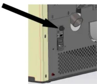
A temperature probe is connected to a safety thermostat above the pellet chute which automatically interrupts the pellet supply in case of excessive heating >85^ . In this case the extractor and/or fans continue working, allowing the stove to cool down rapidly. The fault is displayed on the control panel with a message 'AL 7
THERMAL SAF'. In case of activation, proceed as follows:
Allow the stove to cool down for at least 45 minutes.
Reset the thermostat by pressing the button near the switch on the back of the stove, after unscrewing the protection cap
(figure opposite).
Restart the stove normally.
3.5 Safety against flare-back in the pellet chute
The solutions preventing flare-back are:
negative pressure in the combustion chamber see par. 3.2.
the siphon shape of the pellet chute.
the hopper temperature safety see par. 3.4.
3.6 Overcurrent protection device
The unit is protected against overcurrent by 2A fuses on the power supply of the main stove switch located at the back.
3.7 Power failure safety
In case of brief power failures, the stove relights automatically.
A temporary power failure does not limit stove safety and the hopper temperature does not reach high values (< 85^) , given the small quantity of pellets burning in the brazier.
This anomaly can result in some smoke briefly escaping into the room, which does not involve any risk.

Do not tamper with the safety devices.
3.8 Fume extractor fan failure
If the fume extractor fan stops for any reason, the electronic controller instantly stops the pellet feed, displaying the message 'AL 4 FAN FAIL'.
4 STOVE USE
4.1 Introduction
The pellet stove has the advantage of combining heat from a wood flame with the convenience of automatic management of temperature and the possibility of weekly programming of lighting and shutdown.
For safe and reliable use, observe the following:
- when lighting the stove the first time, unpleasant odours may be created, therefore ensure good ventilation of the room, especially during the first period of operation;
- the hopper must only be filled with pellets, without allowing the bag to come into contact with the hot surfaces of the stove;
- do not put any type of fuel other than recommended wood pellets in the hopper;
- the unit must not be used as a waste incinerator;
- the stove must work only with the fire door always closed;
- the fire door seals should be checked periodically to ensure air tightness;
to ensure efficient and correct operation, it is necessary to clean the brazier whenever pellets are loaded; - when lighting the stove for the first time, make sure to allow it to get hot gradually without overheating;
during lighting, operation and shutdown, the stove may creak a little due to the heat expansion.
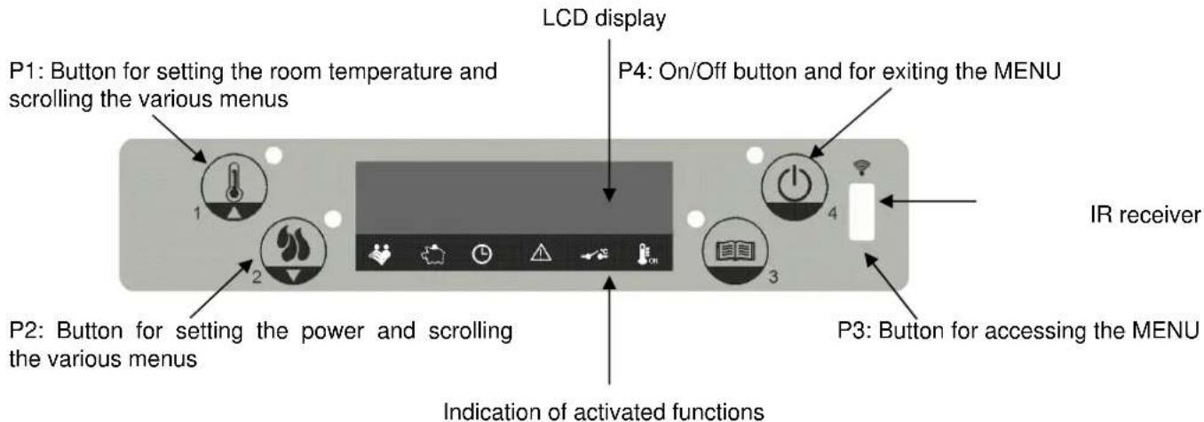
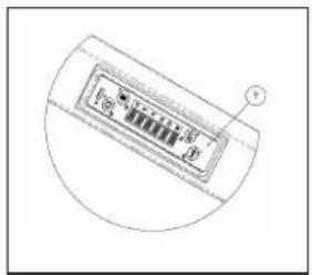
4.2 Control panel
The control of the stove occurs through the use of a control panel provided with four buttons and an LCD display. The panel allows activation and deactivation, adjustment during operation and the setting of management programs and maintenance.
Given below is the control panel and the main functions of the buttons:
4.3 Lighting
Before lighting of the stove, check the following points:
make sure to have read and understood the instructions in the manual;
- the hopper must be filled with pellets;
- the combustion chamber must be clean;
the brazier must be completely free, clean of any combustion residuals and properly positioned in the brazier holder;
- check the hermetic closure of the fire door and ash drawer;

- At first lighting, remove from the stove firebox and glass any components which could burn (instructions/label).
- Any lightings done after long idle periods require complete cleaning of the combustion chamber and the removal of any pellets left in the hopper, in being damp fuel no longer suitable for combustion.
To light the stove, press button P4 on the panel for a few seconds. The message START will appear on the LCD display. This phase is automatic and is managed completely by the electronic control, without any possibility to intervene on the parameters.
The stove carries out the startup phases in sequence according to the procedure defined by the parameters, reaching the work condition. After a certain time, if the fume temperature has not reached the minimum permissible value, the stove goes in alarm status.

- Do not use flammable liquids to light the unit.
- In case of persistent failed lighting, contact the Service Centre.
4.4 Work
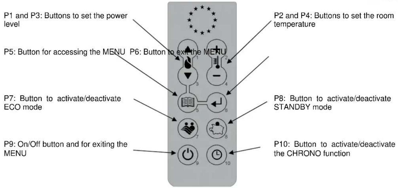
After the startup phase, the stove goes to WORK mode, which is normal operation. The heating power can be adjusted by pressing button P2 and then buttons P1 and P2 from the maximum value of 5 to a minimum value of 1. The stove automatically adjusts the ventilation of hot air according to the set power.
In addition to the power, also the room temperature can be adjusted. Press button P1 and with buttons P1 and P2 make the desired setting, from a maximum value of 40^ to a minimum value of 7^ .

- Make sure to check the pellet level in the hopper so that the flame does not go out due to lack of fuel.
- Make sure the unit is off when loading pellets.
- The pellet hopper cover must always remain closed, to be opened only during fuel loading.
- The bags of pellets must be kept at least 1.5m away from the stove.
When the SET temperature is reached, the corresponding symbol lights up on the display.
If STANDBY mode is activated, the stove shuts down after a delay of several minutes. Restart occurs after the room temperature falls below the set value by a few degrees (default 2^ ).
If STANDBY mode is not activated, or if the fume temperature has reached the set maximum value, the LCD display shows the message MODULATE and the stove activates the flame modulation without any intervention by the user. If the temperature increases again, above a set limit, the HOT FUMES alarm appears and the stove activates the shutdown procedure.
During normal operation in work mode, the BRAZIER CLEANING mode is activated at fixed intervals for a fixed duration of several seconds.
4.5 Shutting down
To turn off the stove, press button P4 for a few seconds. The auger is immediately stopped and the fume exhaust fan goes to high speed, with the message FINAL CLEANING appearing on the display. The fume exhaust and air ventilation motors will remain on until the stove temperature has fallen sufficiently.
At the end of the operation the message OFF will appear on the display.
During the shutdown phase the stove cannot be restarted until the fume temperature has dropped below a fixed value for a given time. If the activation button is pressed the message WAITING COOL will be displayed.
4.6 Menu
Press button P3 to access the menu. It is divided into eleven sub-menus for accessing the settings of the electronic control.
The various sub-menus can be scrolled by pressing buttons P1 and P2, and can be accessed by pressing button P3 and exited by pressing P4.
4.6.1 Menu 01 - adjust fans
To set the hot air flow manually, the fan speed can be selected by choosing a value of 1 to 5; whereas for the fan speed to be automatic and follow the selected power, choose the value A.
4.6.2 Menu 02 - set clock
Before operating with the stove the current time and date must be set in order to have a reference for possible chrono programming.
The electronic control has a 3-volt lithium battery model CR2032 that gives the internal clock with own autonomy of more than 4-5 years; if the clock does not keep the time with stove not powered or a series of zeros appears at restart, battery replacement is necessary: call an authorised service centre.
To set the clock, access the menu by pressing P3 and adjust the time with buttons P1 and P2. Press P3 again to adjust the minutes, day, month and year.
4.6.3 Menu 03 - enable chrono
For enabling all chrono functions. To enable the chrono, access the first sub-menu ENABLE CHRONO and set it to ON with buttons P1 or P2. The corresponding symbol lights up on the display and programming is active. The manual controls of the panel and the remote control retain priority with programming.
Access the second sub-menu DAY PROGRAM to enable or disable the daily chrono with buttons P1 and P2. Then press button P3 to set up to two operation phases delimited by the set times.
Access the third sub-menu WEEK PROGRAM to enable, disable and set the functions of the weekly chrono. Follow the same procedures of the previous paragraph. Up to four operation phases delimited by the set times and days can be set.

Do the programming carefully, without overlapping the activation and/or deactivation times on the same day in different programs.
Access the fourth sub-men WEEKEND PROGRAM to enable, disable and set the chrono functions for the weekend. Follow the same procedures of the previous paragraph. Up to two operation phases delimited by the set times can be set.

To avoid unwanted startup and shutdown operations, activate only one program at a time.
Access the fifth sub-menu to exit the chrono menu and access the main one.
4.6.4 Menu 04 - select language
With this selection it is possible to set the desired language from those available.
4.6.5 Menu 05 - standby mode
By selecting ON in STANDBY mode the corresponding symbol on the display lights up and the stove shuts down automatically when the room temperature has reached the set value for a given time.
The next restart in automatic will be possible only when the room temperature falls below the set value by a few degrees (default 2^ ).
With the OFF selection, the modulation function is active but not the STANDBY mode. Therefore when the temperature exceeds the set value the stove will operate at minimum power.
4.6.6 Menu 06 - buzzer
With this selection it is possible to activate or deactivate the stove alarm buzzer.
4.6.7 Menu 07 - initial loading
Allows the preloading of pellets for a given time. This function can only be activated when the stove is off and cold and is used if the auger is empty due to no more pellets. It is started with button P1 and stops with button P4.
4.6.8 Menu 08 - stove status
This selection is reserved exclusively for the authorised COLA service centre technician.
4.6.9 Menu 09 - settings by technician
This selection is reserved exclusively for the authorised COLA service centre technician.

Modification of the technical parameters of menu 09 must be done by an authorised and competent technician; any modifications made randomly can cause serious damage for which COLA declines any liability.
4.6.10 Menu 10 - settings by technician
This selection is reserved exclusively for the authorised COLA service centre technician.
4.6.11 Menu 11 - ECO mode
The selection ON in the ECO mode limits the stove to operate in modulation, i.e. at minimum power and minimum ventilation. The display shows NIGHT ECO and the corresponding symbol lights up.
4.7 Remote control
The remote control is a device that transmits through an infrared diode. Therefore it must be pointed towards the receiver unit fitted in the control panel.
The remote control allows the following operations:
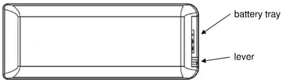
4.7.1 Replacing the battery
The remote control is powered by a 3-volt CR2025 type battery located in the bottom of the device. For its insertion and possible replacement, proceed as follows:
- Operate the lever indicated;
- Pull out the battery tray and replace the battery (3-volt CR2025 model) respecting the polarity;
- Insert the tray;
- Check proper functioning.

- Keep the remote control away from direct heat sources and water.
- The remote control battery must be replaced and disposed of safely in compliance with local regulations;
4.8 Thermostat - external chronothermostat
The standard unit controls the room temperature by means of a digital probe that adjusts the power according to the set temperature.
To use an additional thermostat, contact an authorised technician and proceed as follows:
- turn off the power at the main switch (if available) and disconnect the power cable;
- remove the panels to gain access to the main board;
referring to the wiring diagram, connect the two thermostat wires to the respective terminals TERM on the board (use a 'normally open' type thermostat); - refit everything and check proper functioning
Then set as follows:
external thermostat: set a temperature of 7^
external chronothermostat: set a temperature of 7^ , disable the chrono functionality in the menu 03 and set the STANDBY function to ON. When the set temperature is reached, the stove will shut down and not go to modulation.
In this case, however, it is advisable to use the stove time programming function and only the external chronothermostat set temperature function.
In fact, only with this joint setting is it possible to set STANDBY to ON or OFF, obtaining respectively modulation or shutdown when the SET temperature is reached and likewise obtaining shutdown and lighting according to the set time programming.
When the external thermostat requests stove operation, the corresponding symbol will light up on the display.
4.9 Idle period (end of season)
If the stove is not used for long periods, and/or at the end of each season, it is advisable to proceed as follows
- remove all the pellets from the hopper;
- disconnect the power and remove the power cable;
- clean thoroughly and, if necessary, have any damaged parts replaced by qualified personnel;
- protect the stove from dust with suitable covering;
- store in a dry and safe place protected from atmospheric agents.
5 STOVE CLEANING
Stove cleaning is very important to ensure correct operation and to prevent: blackening of the glass, poor combustion, deposits of ash and unburnt products in the brazier, reduced thermal efficiency.
The stove must only operate with the fire door closed.
The fire door seals must be checked periodically to prevent any air from entering; the combustion chamber and pellet duct work in a negative pressure and the fume exhaust in a positive pressure.
Routine cleaning is normally carried out by the customer following the instructions in the manual, whereas extraordinary maintenance, at least once a year, must be performed by the authorised Service Centre.

- Cleaning operations for all parts must be carried out with the stove unplugged and cold;
- Dispose of cleaning waste in accordance with the current local regulations;
- The stove must not be operated without its cladding;
- Avoid the creation of smoke and unburnt products during lighting and/or normal operation.
Given below are the control and/or maintenance operations for correct stove use and operation.
| Parts / PeriodType of cleaning | 1 dayroutinecleaning | 2-3 daysroutinecleaning | 1 monthroutinecleaning | 2-3 monthsroutinecleaning | 1 yearextraordinarycleaning: carried outby the Service Centre |
| Brazier | ■ | ||||
| Ash compartment pan | ■ | ||||
| Glass | ■ | ||||
| Baffle - fume exchanger | ■ | ■ | |||
| Manifold - fume extractor | ■ | ■ | |||
| Glass - door seal | ■ | ||||
| Pipe - flue connection | ■ |
5.1 Cleaning the brazier
Remove the brazier and the ash deposited in the combustion chamber and brazier holder. A suitable vacuum cleaner may be used for this purpose. This operation must be carried out daily, especially in case of accumulated unburnt matter, to ensure perfect combustion conditions, since the brazier holes allow the flow of combustion air.
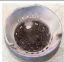
Brazier dirty
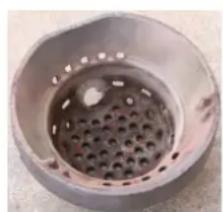
Brazier clean
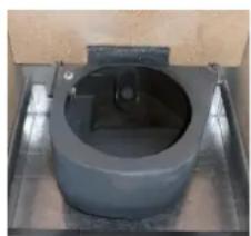
Brazier Holder clean

The brazier must rest on the brazier holder and precisely on the entire ring band without air gaps.
5.2 Cleaning the ash container
The ash container is located directly under the brazier - brazier holder. To clean it, open the fire door and remove the ash and any combustion residuals using a suitable vacuum cleaner.
The door must be closed after cleaning. The ash container can be cleaned every 2-3 days depending on stove use.
5.3 Cleaning the glass and air slots
The glass can be cleaned using a damp cloth and specific non-abrasive detergents.
Special slots between the glass, glass stops and fire door at the top and bottom allow air to circulate on the inside surface of the glass. These slots must be kept clean of any deposits of ash and dust. Therefore periodically clean all around the the inner side of the glass.
5.4 Cleaning the fume extractor and combustion chamber
The combustion chamber must be cleaned at least once a year, removing all combustion residuals from the internal baffles and flueways. To do this, remove the cover and the top front panel of the stove. Remove the cast iron exchanger by undoing the fixing screws then clean the baffles and the chamber.
Also make sure to clean the fume extractor located under the chamber, accessed by removing the inspection port located on the front lower part of chamber.
Every 3-4 months clean the inside walls (insulating-refractory) of the combustion chamber using suitable equipment (brushes) and replace them if necessary.
Every 1800 hours of operation, by means of a message 'SERVICE DUE', the stove signals the need for extraordinary maintenance (not under warranty) to be performed by qualified personnel who will carry out complete cleaning and reset the message.

Any knocking or forcing can damage the fume extractor, making it noisy during operation; therefore it is advisable to have this operation carried out by qualified personnel.
5.5 Cleaning the air flow meter
The air flow meter (it measures the flow of combustion air) installed inside the inlet pipe requires periodical internal cleaning every 3-4 months, using suitable equipment (blowing compressed air or suitable brushes).
5.6 Cleaning the ceramic surfaces (ceramic models)
The ceramic tiles are handicraft products and therefore may have minor surface imperfections such as tiny spots or slight colour differences. It is advisable to use a soft dry cloth to clean the ceramic surfaces; the use of detergents could highlight any flaws.
5.7 Cleaning the flue - flue connection
The flue connection must be cleaned at least once a year or whenever necessary depending on stove use and the type of installation.
Cleaning requires the suction and removal of the residuals in all the vertical and horizontal sections as well as the bends from the stove to the flue.
It is advisable to also clean the flue every year, to ensure correct and safe evacuation of fumes.

For any maintenance or end of season cleaning, COLA recommends contacting an authorised service centre, which will also check the wear on the stove's internal components.
6 MAINTENANCE
6.1 Introduction
Operations on the internal parts of the stove must be carried out by qualified personnel. Contact the nearest authorised service centre.

Make sure the stove is unplugged and cold before carrying out any work on it.
6.2 Removing the cladding
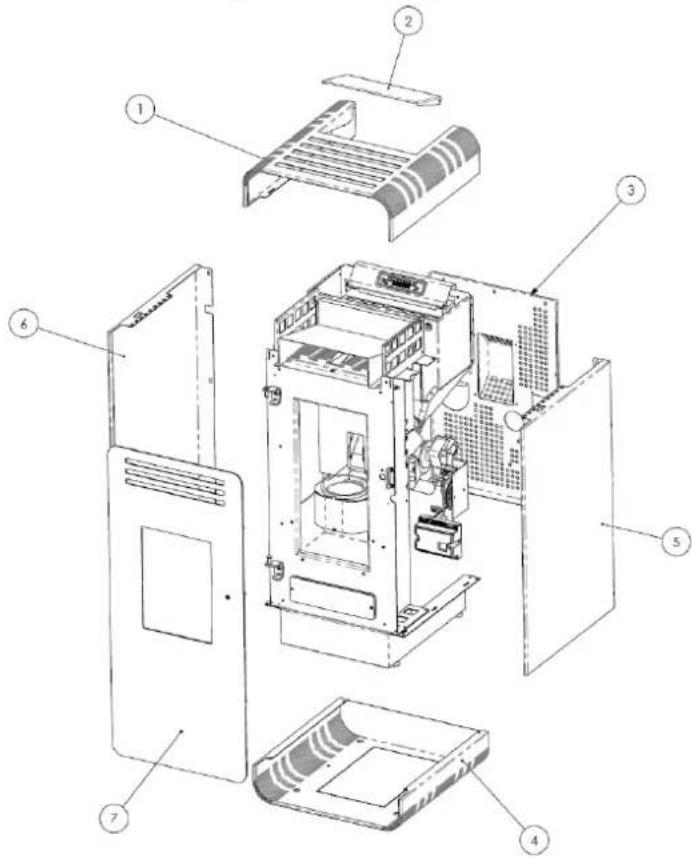
Key:
1 - Top cover steel
2 - Pellet hopper cover
3 - Rear Panel
4 - Protection motor
5 - Lateral panel right
6 - Lateral panel left
6.3 Stove internal parts
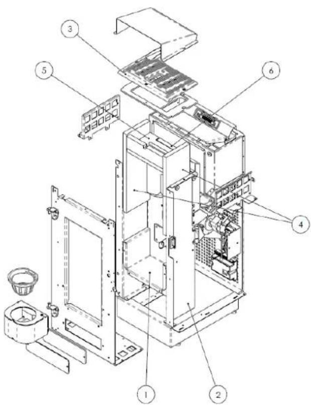
Key:
1 - Combustion chamber
2 - Support boundary
3 - Cast iron exchanger
4 - Vermiculite side walls
5 - Vermiculite upper baffle
6 - Vermiculite rear wall
Exploded view of LIRA stove combustion chamber and parts
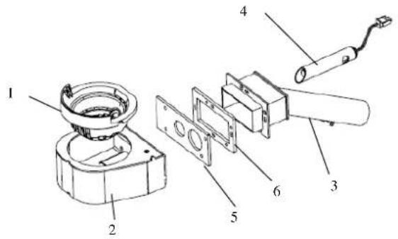
6.4 Electrical components
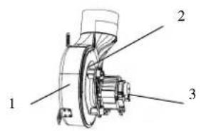
Exploded views of:
1 - Brazier assembly
2 - Fume extractor assembly
3 - Auger assembly
Key:
1-Brazier
2 - Brazier holder
3 - Combustion air inlet pipe assembly
4 - Electrical element
5 - Brazier holder rear seal
6 - Suction unit front seal
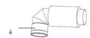
Key:
1 - Fume extractor volute
2 - Thermal seal
3 - Fume extractor motor
4 - Fume exhaust pipe
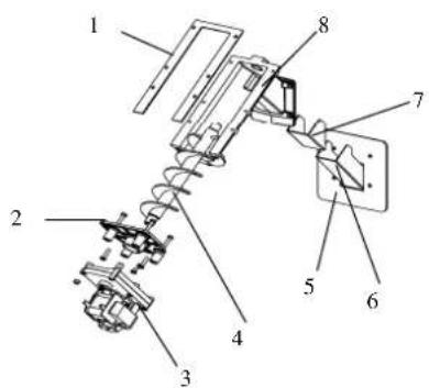
Key:
1 - Conveyor - hopper seal
2 - Gearmotor support flange
3 - Gearmotor
4 - Auger
5 - Seal for chute
6-Pellet chute
7 - Conveyor-chamber seal
8-Pellet conveyor
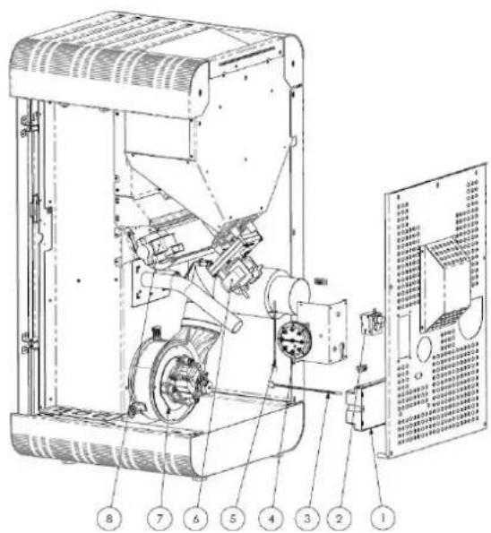
Key:
1 - Electronic board O100
2 - Safety thermostat
3 - Room probe
4 - Control and safety vacuum switch
5 - Fume probe
6-Gearmotor
7-Fume extractor
8-Rear tangential fan
11- Control panel mod.N032
7 TROUBLESHOOTING
7.1 Alarm management
Alarms are indicated by an acoustic signal (if activated) and a message on the control panel.
In case of an alarm the shutdown procedure is automatically activated. Cancel the signalling by pressing button P4
and wait until the stove reaches OFF status. Eliminate the cause and restart the stove according to the normal
procedure described in this manual.
Listed below are the alarms that can appear on the control panel, with the causes and cures:
| ALARMS - MESSAGES | |||
| Signalling | Fault | Possible causes | Cures |
| AL 1 POWER FAILURE | Occurs in case of a power failure during the operation phase | Electrical system power failure in the stove installation room | - Turn the stove OFF by pressing button P4 and repeat the lighting procedure - Other reinstatement operations must be carried out by a service centre |
| AL 2 FUME PROBE | Occurs in case of a fume temperature detection probe fault | - Probe fault - The probe is disconnected from the board | Reinstatement operations must be carried out by a service centre |
| AL 3 HOT FUMES | Occurs if the probe detects a high fume temperature | - Overheating due to use of the stove for too long - The tangential fan is faulty or not powered - Excessive pellet load | - Wait for the stove to cool and repeat the lighting procedure - Other reinstatement operations must be carried out by a service centre |
| AL 4 FAN FAIL | Occurs when the fume exhaust fan is faulty | - The fume fan is blocked - The speed control sensor is faulty - No power to the fume fan | Reinstatement operations must be carried out by a service centre |
| AL 5 NO IGNITION | Pellets do not ignite in the lighting phase | - The pellet hopper is empty. - The heater is faulty, dirty or incorrectly positioned. - Incorrect pellet load setting. | - Check the presence of pellets in the hopper. - Repeat the lighting procedure - Other reinstatement operations must be carried out by a service centre |
| AL 6 NO PELLETS | The flame goes out during the operation phases | - The pellet hopper is empty - The pellet feed gearmotor is faulty or not powered | - Check the presence of pellets in the hopper - Repeat the lighting procedure - Other reinstatement operations must be carried out by a service centre |
| AL 7 THERMAL SAF | Occurs in case of intervention of the auger duct temperature safety thermostat. | - Overheating due to use of the stove for too long - Brazier clogged with excessive accumulated ash | Reset the safety thermostat by pressing the reset button and repeat the lighting procedure |
| AL 8 NO NEG PRESS | In the work phase the stove detects a pressure lower than the vacuum switch threshold setting | - The combustion chamber is dirty - The fume duct is blocked - The fire door is not closed - The overpressure valves are open-jammed - The vacuum switch is faulty | - Check the cleanness of the fume duct and the combustion chamber, hermetic closure of the door and the overpressure valve. Then repeat the lighting procedure - Other reinstatement operations must be carried out by a service centre |
| AL 9 INSUFF DRAUGHT | The combustion air flow has dropped below a predefined threshold | - The combustion chamber is dirty - The fume duct is blocked - The fire door is not closed - The overpressure valves are open-jammed - The air flow meter is dirty or faulty | - Check the cleanness of the flue pipe, the combustion chamber and the air flow meter; hermetic closure of the door and the overpressure valves. Then repeat the lighting procedure - Other reinstatement operations must be carried out by a service centre |
| AL b AUG TRIAC ERROR | Occurs when the gearmotor runs continuously | - Incorrect parameters entered - Faulty main board | Reinstatement operations must be carried out by a service centre |
| AWAITING COOL | Occurs on relighting the stove immediately after turning it off | Stove still too hot to start a lighting phase | Wait for the stove to cool and repeat the lighting procedure |
| AIR FLOW METER FAILURE | Occurs when the air flow meter is disconnected. The control does not detect the amount of combustion air and does not shut down the stove | The air flow meter connection cable has been disconnected | The stove continues its normal operation and safety is guaranteed by the remaining devices. It is advisable to contact a service centre as soon as possible |
| SERVICE DUE | Occurs when the stove has exceeded the hours of operation since the previous service | The stove requires extraordinary maintenance | The stove continues its normal operation. It is advisable to contact a service centre as soon as possible |
8 ENCLOSURES
CE MARKING INFORMATION
| CE | |
| FERROLI | |
| 2013 | |
| EN 14785 : 2006 | |
| Wood pellet-burning domestic heating appliances Ref. LIRA | |
| Min. safety distance from flammable materials rear, right/left side, floor | 200 - 300 - 0 mm |
| CO emissions at 13% O2 in fumes | Nom. output: 0.02% Red. output: 0.02% |
| Dust emissions at 13% O2 in fumes | Nom. output: 19.5 mg/m3 |
| Dust emissions at 13% O2 in fumes | Red. output: - mg/m3 |
| Max. water operating pressure Max. water operating pressure | - bar |
| Flue gas temperature : | Nom. output 152.6 °C Red. output 84 °C |
| Nominal and reduced heat output : | Nom. output 6.51 kW Red. output 2.3 kW |
| Efficiency : | Nom. output 89.1% Red. output 92.2% |
| Types of fuel : | Wood pellets |
| Electrical power : | 420 W max - 120 w |
| Rated voltage : | 230 V |
| Rated frequency : | 50 Hz |
1. RECOMMANDATIONS GENÉRALES
1.4 Description technique
raccordement conditionnel ;
2.1 Emballage, manutention, expulsion et transport
INFORMATIONS RELATIVES AU MARQUAGE CE
CE MARKING INFORMATION
| CEFERROLI | |
| 2013 | |
| EN 14785: 2006 | |
| Aparatos de calefacción dométrica alimentados con pellets de madera Residential space heating appliance fired by wood pellets Ref. LIRA | |
| Distancia minima de sécurité de materiales inflamables (detrás, derecha, izquierda, sueño) Minimum safety clearance distance from combustible materials rear, right side, left side, floor | 200 - 300 - 0 mm |
| Emissiones de CO al 13 % O2 en los productos de combustión | P_nom.: : 0,02 % |
| Emission of CO to 13%O2 in combustion products | P.red.: : 0,02% |
| Emissiones de polvo al 13 % O2 en los productos de combustión | P_nom.: 19,5 mg/m3 |
| Dust emission to 13% O2 in combustion products | P.red.: - mg/m3 |
| Presión hidraca的最大の funcimiento: - bar Maximum water operating pressure | |
| Temperatura de humos | P_nom. 152.6 °C |
| Flue gas temperature | P.red. 84 °C |
| Potencia tírmica nominal y reducida | P_nom. 6.58 kW |
| Nominal and reduced heat output | P.red. 2.3 kW |
| Rendimiento | P_nom. 91,51 % |
| Energy efficiency | P.red. 92,2 % |
| Tipos de combustibles | Pellets de madera |
| Fuel types | Wood pellets |
| Potencia electrica | 420 W max. - 120 W |
| Rated input power | |
| Tensión nominal | 230 V |
| Rated voltage | |
| Frecuencia nominal | 50 Hz |
| Rated frequency | |


- FR 48-69
- CE MARKING INFORMATION
- TRANSPORT AND INSTALLATION
- STOVE SAFETY
- STOVE USE
- STOVE CLEANING
- MAINTENANCE
- TROUBLESHOOTING
- ENCLOSURES
- GENERAL INFORMATION
- Introduction
- Using the manual
- Safety rules.
- Technical description
- Permissible use and fuel
- Accessories supplied
- Reference standards
- Dataplate
- Stove decommissioning
- Instructions for requesting assistance and replacement parts
- TRANSPORT AND INSTALLATION
- Packing, handling, shipment and transport
- Place of installation, positioning and fire-prevention safety
- Air inlet
- Fume exhaust
- Types of installation
- Brazier and baffle position check
- Electrical connection
- Wiring diagram
- Emergency
- STOVE SAFETY
- Safety distance from flammable materials
- Fume exhaust safety
- Combustion chamber overpressure safety
- Overheating - pellet hopper temperature safety thermostat
- Safety against flare-back in the pellet chute
- Overcurrent protection device
- Power failure safety
- Fume extractor fan failure
- STOVE USE
- Introduction
- Control panel
- Lighting
- Work
- Shutting down
- Menu
- Menu 01 - adjust fans
- Menu 02 - set clock
- Menu 03 - enable chrono
- Menu 04 - select language
- Menu 05 - standby mode
- Menu 06 - buzzer
- Menu 07 - initial loading
- Menu 08 - stove status
- Menu 09 - settings by technician
- Menu 10 - settings by technician
- Menu 11 - ECO mode
- Remote control
- Replacing the battery
- Thermostat - external chronothermostat
- Then set as follows:
- Idle period (end of season)
- Cleaning the brazier
- Cleaning the ash container
- Cleaning the glass and air slots
- Cleaning the fume extractor and combustion chamber
- Cleaning the air flow meter
- Cleaning the ceramic surfaces (ceramic models)
- Cleaning the flue - flue connection
- Introduction
- Removing the cladding
- Key:
- Stove internal parts
- Electrical components
- Exploded views of:
- Alarm management
- RECOMMANDATIONS GENÉRALES
- Description technique
- Emballage, manutention, expulsion et transport
- INFORMATIONS RELATIVES AU MARQUAGE CE
Brand : FERROLI
Model : Lira
Category : Heating