
Varese - Heating FERROLI - Free user manual and instructions
Find the device manual for free Varese FERROLI in PDF.


| Product Type | Gas-fired wall-mounted condensing boiler |
| Brand | Ferroli |
| Model | Varese |
| Category | Heating |
| Energy Source | Natural gas or LPG |
| Heating Output (P) | 24 kW (adjustable) |
| Efficiency | Up to 93% (condensing) |
| Dimensions (H x W x D) | 700 x 400 x 300 mm |
| Weight | 30 kg |
| Water Connection | Gas: 3/4 inch; Heating flow/return: 1/2 inch |
| Expansion Vessel Capacity | 8 liters |
| Max Operating Pressure | 3 bar |
| Temperature Range | 30 - 80 °C |
| Control Interface | Electronic with LCD display and push buttons |
| Safety Features | Overheat protection, frost protection, flame failure device, pressure relief valve |
| Maintenance | Annual service by qualified technician recommended |
| Spare Parts Availability | Through authorized Ferroli distributors and service centers |
| Warranty | 2 years (extendable with registration) |
Frequently Asked Questions - Varese FERROLI
User questions about Varese FERROLI
0 question about this device. Answer the ones you know or ask your own.
Ask a new question about this device
Download the instructions for your Heating in PDF format for free! Find your manual Varese - FERROLI and take your electronic device back in hand. On this page are published all the documents necessary for the use of your device. Varese by FERROLI.
USER MANUAL Varese FERROLI
LOW TEMPERATURE RADIATOR
RADIATORE A BASSA TEMPERATURA

natural_image
Two white rectangular electronic devices with ventilation grilles, placed against an orange and blue textured background (no visible text or symbols)Mod.
VARESE
VARESE LP
VARESE HE
VARESE LP HE
A73022040 REV.0 25/01/2018
CE
Thank you for purchasing a FERROLI air conditioner. The result of many years of experience, it features advanced design, cutting-edge technology and top quality construction. The CE marking also ensures that the units meet the requirements of the European Machinery Directive on safety. The quality level is constantly monitored, therefore FERROLI products are synonymous with Safety, Quality and Reliability.
If not known, ask the dealer from whom the unit was purchased for our nearest After-Sales Service.
The data may undergo changes deemed necessary for product improvement.
Thank you again.
FERROLI S.p.A
Gentile cliente,
The Manufacturer declines any liability for inaccuracies contained in this manual, if due to printing or copying errors. The Manufacturer reserves the right to make changes and improvements to the catalogue products at any time without notice.
natural_image
Abstract line drawing with intersecting curves and a diagonal line (no text or symbols)D. Enrique Jiménez Marín
DIRECTOR DE FÁBRICA
natural_image
3D rendering of a modular electronic enclosure with a door open and a side panel showing internal components (no text or symbols visible)natural_image
3D rendering of two industrial electronic modules with visible internal components (no text or symbols)natural_image
3D rendering of an electronic device showing a rectangular housing with internal components and a separate open panel (no text or symbols visible)natural_image
3D rendering of an electronic device showing a panel with a shield and internal components (no text or symbols visible)natural_image
Pure diagram of a rectangular panel with internal components and no text or symbols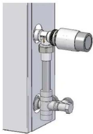
natural_image
Mechanical assembly diagram showing a pipe fitting mounted on a vertical panel (no text or symbols visible)natural_image
Technical diagram of a rectangular enclosure with coiled copper pipes and mounting brackets (no text or symbols)
natural_image
3D CAD rendering of a mechanical assembly with three fans and tubing (no visible text or symbols)natural_image
Diagram of a row of test tubes with directional arrows indicating flow or movement (no text or symbols present)natural_image
Diagram of a cylindrical structure with horizontal and vertical lines, marked with blue and red arrows (no text or symbols)natural_image
Pure diagram of vertical cylindrical structures with arrows indicating left and right directions (no text or symbols)natural_image
Technical line drawing of a heat exchanger or cooling unit with coiled ducts and cooling fins (no text or symbols)- Tomas de 1/2" hembra
natural_image
Technical diagram showing a rectangular frame with two side supports and red X marks, labeled Fig. 21 (no text or symbols on the diagram itself)
natural_image
3D diagram of a mechanical housing with four curved pipe fittings and red arrows indicating direction (no text or symbols)natural_image
Illustration of a blue door with a metallic handle and a circular opening, held by a hand (no text or symbols visible)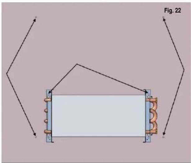
natural_image
Pure electrical circuit lines without any symbols
natural_image
Diagram of a rectangular frame with internal coils and mounting brackets, labeled Fig. 23 (no text or symbols on the diagram itself)natural_image
3D rendering of a vertical panel with two circular holes, shown from an angle (no text or symbols)
natural_image
3D CAD model of a vertical panel with two circular nuts, shown in Fig. 25 (no text or symbols on the components)natural_image
Technical diagram of a mechanical assembly with spring-loaded components and mounting brackets (no text or symbols)natural_image
Pure diagram of a rectangular panel with internal components and no visible text or symbolsnatural_image
Technical diagram showing a rectangular frame with two side supports and red X marks, labeled Fig. 28 (no text or symbols on the diagram itself)
natural_image
3D diagram of a mechanical component with four curved pipe fittings and red alignment lines, labeled Fig. 28b (no text or symbols on the diagram itself)natural_image
3D rendering of a blue box with a circular handle and a small circular hole, no visible text or symbols
natural_image
Pure electrical circuit lines without any symbolsnatural_image
Simple line drawing of a door with a circular knob (no text or symbols)
natural_image
Technical diagram of a rectangular frame with internal pipes and a central rectangular block, labeled Fig. 31 (no text or symbols on the diagram itself)natural_image
3D diagram of a vertical panel with two circular holes, shown in technical view (no text or symbols)
natural_image
3D CAD model of a mechanical assembly with copper coils and a central circular component, labeled Fig. 32 (no text or symbols on the diagram itself)natural_image
Diagram of a mechanical component with a cylindrical part inserted, labeled Fig. 33 (no text or symbols on the diagram itself)
natural_image
Blank white rectangular panel with a small black square and label 'Fig. 34' at top (no other text or symbols)CONEXION DEL SISTEMA HE
natural_image
Diagram showing two configurations of copper inductors mounted on metal plates, labeled Fig. 35 and Fig. 36 (no text or symbols on the diagram itself)
natural_image
3D mechanical assembly showing a pipe connection with a tool, no visible text or symbols
natural_image
3D CAD model of a coiled copper pipe inside a metal enclosure, with no visible text or symbols
natural_image
Technical diagram showing a mechanical assembly with labeled components and a magnified view of internal components (no text or symbols present)
natural_image
3D CAD rendering of a mechanical assembly with copper pipes, a yellow hexagonal nut, and a connected electrical connector (no text or symbols)natural_image
3D technical illustration of an open industrial enclosure with internal components (no text or symbols)Fig. 44
ESQUEMA ELÉCTRICO ( MODELOS HE )
Fig. 45

flowchart
graph LR
    A["230V AC"] --> B["AC/DC"]
    B --> C["Control"]
    C --> D["M1"]
    C --> E["M2"]
    C --> F["M3"]
    B --> G["L"]
    B --> H["N"]
    B --> I["S1"]
    B --> J["S2"]
    C --> K["12V CC"]
    K --> L["+"]
    L --> C
Unit description.... 25
Purpose of device 25
Versions available.... 25
General features.... 26
Main components.... 26
Types of installation supported.... 28
Technical specifications table.... 32
Dimensions.... 32
Position of hydraulic connection sockets.... 33
Unit installation.... 34
One-pipe systems.... 34
Two-pipe systems.... 36
HE system connection.... 38
Operation 39
HE System Operation.... 39
Cleaning and Maintenance....41
Electric Diagram 41
PURPOSE
The VARESE emitters are high performance radiators suitable for heating at low temperature, with very low water content and straightforward installation.
VERSIONS AVAILABLE
VARESE
Fig. 1
natural_image
3D rendering of an open industrial enclosure with a side panel and internal components (no text or symbols visible)Low temperature emitter without HE kit. Reversible, suitable for new constructions or replacement. Galvanized sheet cover with epoxy-polyester paint, copper/aluminium exchanger with twin bleeders.
VARESE LP
Fig. 2

natural_image
3D rendering of a modular electronic device with two views: one open showing a flat panel, the other closed showing a rectangular housing with internal components (no text or symbols visible)Low temperature emitter without HE kit. Low level for installation beneath windows Reversible, suitable for new constructions or replacement. Galvanized sheet cover with epoxy-polyester paint, copper/aluminium exchanger with twin bleeders.
VARESE HE
Fig. 3

natural_image
3D rendering of an electronic device showing a rectangular housing with internal components and a separate open panel (no text or symbols visible)Low temperature emitter with HE kit, brushless fans, temperature control sensors and touch panel. Reversible, suitable for new constructions or replacement. Galvanized sheet cover with epoxy-polyester paint, copper/aluminium exchanger with twin bleeders.
VARESE LP HE
Fig. 4

natural_image
3D rendering of an electronic device showing a panel with a shield and internal components (no text or symbols visible)Low temperature emitter with HE kit, brushless fans, temperature control sensors and touch panel. Low level for installation beneath windows Reversible, suitable for new constructions or replacement. Galvanized sheet casing with epoxy-polyester paint, copper/aluminium exchanger with twin bleeders..
MAIN COMPONENTS
- Exterior cover: galvanized sheet steel, painted with high durability epoxy-polyester type paint, with removable front grille and high in strength. Exit holes for electro thermostatic valves and / or pre-drilled hydraulic taps.
- Heat exchanger: Exchanger with corrugated aluminium fins and expanded copper pipes, 2 ranges and 4 rows. Reversible for socket connection to the right or to the left.
- HE set of controls: VARESE HE electronic control system with touch panel
- Fans kit: Fan assembly (the number depends on the model) for ultra-quiet brushless type and low power consumption.
- Room temperature sensor: NTC probe for measuring the ambient temperature of the room.
- Water inlet temperature sensor
- Hydraulic connections: 12 female type water inlet and outlet sockets with twin and symmetrical type steam bleeders.
COMPONENTS DESCRIPTION
- Exterior cover: galvanized sheet steel, painted with high durability epoxy-polyester type paint, with removable front grille and high in strength. Exit holes for electro thermostatic valves and / or pre-drilled hydraulic taps.
- Heat exchanger: Exchanger with corrugated aluminium fins and expanded copper pipes, 2 ranges and 4 rows. Reversible for socket connection to the right or to the left.
- HE set of controls: VARESE HE electronic control system with touch panel
- Fan assembly (the number depends on the model) for ultra-quiet brushless type and low power consumption.
- Room temperature sensor: NTC probe for measuring the ambient temperature of the room.
- Water inlet temperature sensor
- Hydraulic connections: 12 female type water inlet and outlet sockets with twin and symmetrical type steam bleeders.
VARESE / VARESE LP
Fig. 5b

COMPONENT DESCRIPTION
- Exterior casing: in galvanized sheet steel, painted with high durability epoxy-polyester type paint, with removable front grille and high strength. Exit holes for electro thermostatic valves and / or pre-drilled hydraulic taps.
- Heat exchanger: Exchanger with corrugated aluminium fins and expanded copper pipes, 2 ranges and 4 rows. Reversible for right or Reversible left-hand side connection.
- Trim
- Hydraulic connections: 12 female type water inlet and outlet sockets with twin and symmetrical type bleeders.
TYPES OF INSTALLATION SUPPORTED
The VARESE emitters are suitable for one-pipe and two-pipe heating installations, in new constructions or the replacement of previously installed radiators, with possibility of right or left-hand side connection.
Examples of one- and two-pipe installation are below. In all of them the option for connection on the right hand is shown, but all can be carried out with left-hand connections without changing the model.
*NOTE: All valves, fittings, pipes, ducts etc. shown are not supplied in any context by VARESE range suppliers.
ONE-PIPE INSTALLATIONS
Figs. 6 y 7

natural_image
Exterior view of a rectangular industrial or mechanical component with attached pipes and fittings (no visible text or symbols)
natural_image
Technical illustration of a mechanical valve assembly with no visible text or symbolsSuitable for right or left-hand side connection. Exposed valves. The use of valves with curve for water inlet at the upper outlet.
TWO-TUBE INSTALLATION NEW CONSTRUCTION
Figs. 8 y 9
natural_image
Technical diagram of a rectangular frame with coiled copper pipes and labeled corner points (no text or symbols)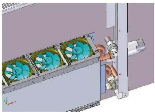
natural_image
3D mechanical assembly diagram showing fan cooling system with cooling unit and pipe connection (no text or symbols)Suitable for right or left-hand side connection. Concealed valves with exposed thermostat and accessible from the outside
REPLACEMENT TWO-TUBE INSTALLATION
Figs. 10 y 11
natural_image
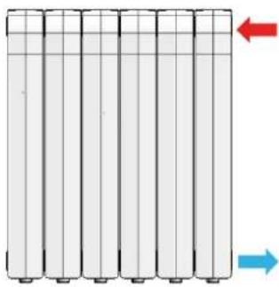
Pure diagram of vertical cylindrical objects with grid lines and directional arrows, no text or symbols presentUpper entry, lower return on the same side.

- Wall outlet
-
- Connecting piping with upper connection socket (by the installer)
-
- Upper water inlet connection socket (fitting by the installer)
-
- Electro thermostatic valves (by the installer)
-
- Lower water outlet socket Wall inlet (fitting by the installer)
Figs. 12,13 y 14

natural_image
Diagram of a cylindrical container with horizontal lines and two arrows indicating direction (no text or symbols)Upper inlet, lower outlet on the opposite side.
- Wall outlet
- Connecting piping with upper socket (by the installer)
- Upper water inlet socket (fitting by the installer)
- Electro thermostatic valves (by the installer)
- Lower water outlet socket Wall inlet (fitting by the installer)
- Connecting piping with lower connection socket. (by the installer)
- Wall inlet (fitting by the installer)
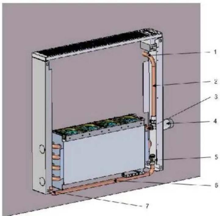
Option A: return wall socket inside the cabinet
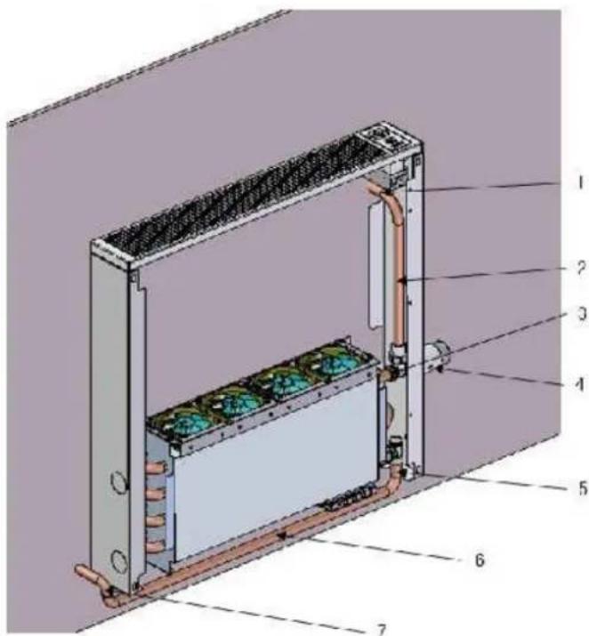
Option B: return wall socket outside the cabinet
Figs. 15 y 16

natural_image
Pure diagram of vertical cylindrical structures with arrows indicating direction, no text or symbols presentUpper inlet, lower outlet on the opposite side.
-
Upper water inlet socket with bleeder (fitting by the installer)
-
Electro thermostatic valves (by the installer)
-
Connecting piping with upper connection socket (by the installer)
-
Wall outlet
-
Lower water outlet socket Wall inlet (fitting by the installer)
-
Connecting piping with lower connection socket with bleeder. (fitting by the installer)
-
Wall inlet (fitting by the installer)
TABLE OF VARESE HE MODEL SPECIFICATIONS
| MODEL Ud. 500 HE 600 HE | 800 HE | 1000 HE | LP 500 HE | LP 600 HE | LP 800 HE | LP 1000 HE | ||||
| Heat output 55/45/20 °C* | Eco Mode | W | 447 | 604 | 879 | 1138 | 369.8 | 576.5 | 842 | 1050.3 |
| Comfort Mode | W | 498.6 | 651 | 940 | 1228.6 | 401.1 | 617.5 | 915.6 | 1131.6 | |
| Boost Mode | W | 569.6 | 767.2 | 1112.6 | 1517 | 484 | 710 | 1087.6 | 1493.3 | |
| Max Heat Output 75/65/20 °C* | W | 1067.4 | 1402.3 | 1981.4 | 2637.2 | 997.7 | 1325.6 | 1855.8 | 2581.4 | |
| Max Heat Output 70/50/20 °C* | W | 823.3 | 1074.4 | 1479.1 | 1995.3 | 753.5 | 1032.6 | 1395.3 | 1939.5 | |
| Water content | I | 0.48 | 0.62 | 0.835 | 1.095 | 0.48 | 0.62 | 0.835 | 1.095 | |
| Female hydraulic | - | 1/2" female | ||||||||
| Maximun pressure | bar | 10 | ||||||||
| No. fans | Ud. | 3 | 4 | 6 | 8 | 3 | 4 | 6 | 8 | |
| Type fans | - | Electronically commutated-type DC brushless fans. | ||||||||
| Sound pressure (comfort)** | dB | 29 | 30.2 | 32 | 33.2 | 29 | 30.2 | 32 | 33.2 | |
| Max.power consumption | W | 3.5 | 5 | 8 | 10.5 | 3.5 | 5 | 8 | 10.5 | |
Tab.1
*Input/Output/Ambient
**In reverberation chamber, T.rev = 0.6s, Vol.reference = 80 m3
TABLE OF VARESE MODEL SPECIFICATIONS
| MODELO | Ud. | 500 | 600 | 800 | 1000 | LP 500 | LP 600 | LP 800 | LP 1000 |
| Heat Output 55/45/20 °C* | W | 195.3 | 244.2 | 348.8 | 509.3 | 153.5 | 209.3 | 293 | 348.8 |
| Max Heat Output 75/65/20 °C* | W | 376.7 | 523.3 | 795.3 | 1060.5 | 334.9 | 439.5 | 676.7 | 837.2 |
| Max Heat Output 70/50/20 °C* | W | 265.1 | 390.7 | 607 | 795.3 | 237.2 | 334.9 | 537.2 | 600 |
| Water content | I | 0.48 | 0.62 | 0.835 | 1.095 | 0.48 | 0.62 | 0.835 | 1.095 |
| Female hydraulic | - | 1/2" female | |||||||
| Maximun pressure | bar | 10 | |||||||
*Input/Output/Ambient
Tab.2
DIMENSIONS

Tab.3
| Models | LP 500 | LP 500 HE | LP 600 | LP 600 HE | LP 800 | LP 800 HE | LP 1000 | LP 1000 HE |
| A (mm) | 545 | 545 | 654 | 654 | 879 | 879 | 1094 | 1094 |
| Welkght (Kg) | 5.0 | 5.8 | 5.8 | 6.8 | 7.5 | 8.8 | 9.0 | 10.6 |
Fig. 18
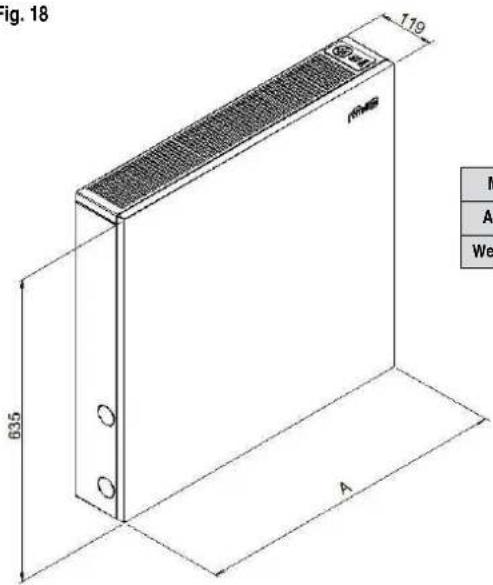
Tab.4
| Model 500 | 500 HE 600 | 600 HE 800 | 800 HE 1000 | 1000 HE | ||||
| A (mm) 545 | 545 654 654 | 879 879 1094 | 1094 | |||||
| Weigt (Kg) 7.1 | 7.9 8.3 9.3 | 10.5 11.9 12.5 | 14.2 |
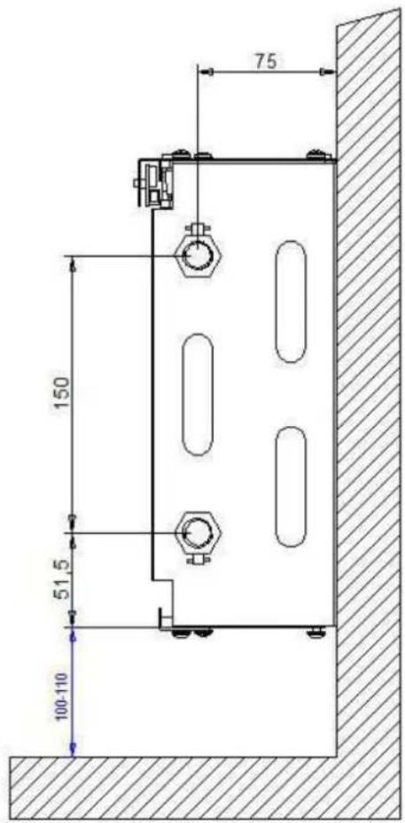
POSITION OF HYDRAULIC CONNECTIONS
Figs. 19 y 20

natural_image
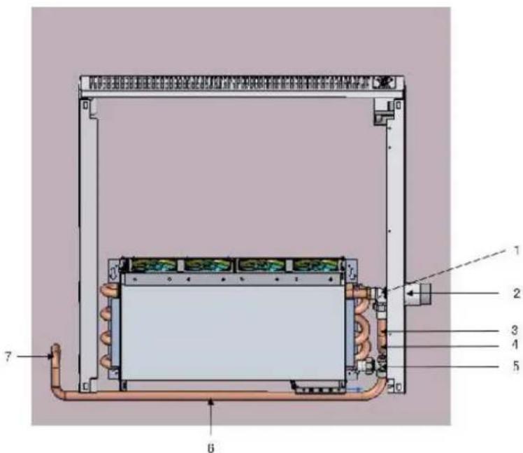
Technical line drawing of a heat exchanger or cooling unit with multiple cooling fans and piping (no text or symbols)• 1/2" female socket connections
- 75 mm from the wall
- Reversible
• Water intake always through higher inlet
ONE PIPE SYSTEMS
- Remove the clamps for transporting the heat exchanger (Fig.21), as well as the plugs from top and bottom emitter sockets.
- Also remove the rubber plugs heat exchanger.
CAUTION: The battery is supplied at a pressure of 1.5 bar pressure with nitrogen to ensure no leakage (Fig.21b).

natural_image
Technical diagram showing a structural frame with two X marks, no text or symbols present
natural_image
3D diagram of a mechanical component with copper-colored pipes and red arrows indicating direction (no text or symbols)- Using the template provided on the back of the package, mark on the wall the anchoring points (2 locations) for the battery, taking into account the position of the water inlets (right or left). Also, check the position of the four attachment points of the outer cover, taking into account the measurement of the taps/valves/fittings to be used.
- Drill the holes carefully and insert a plug for each anchor point. We recommend using 8 mm diameter plugs.
- Position the heat exchanger.

- Place the outer over onto the holes

natural_image
Illustration of a blue door lock with a handle and circular opening (no text or symbols)
natural_image
Technical diagram of a rectangular frame with internal coils and mounting brackets, labeled Fig. 23 (no text or symbols on the diagram itself)
natural_image
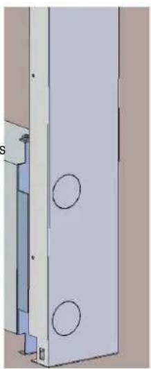
Pure mechanical component diagram without any text, numbers, or symbols- Using a small rubber hammer, open the holes in the co-ver enough to place the inlets on the desired side and place the cover over the previously prepared holes
natural_image
Technical diagram of a vertical panel with two circular holes, shown in 3D perspective (no text or symbols)
natural_image
3D CAD model of a mechanical assembly with two circular components mounted on a vertical panel (no text or symbols visible)- Connect the one-pipe keys and thermostatic valve. With one-pipe installations, the use of valves with a curve for the upper hot water inlet is required.
- When water begins to fill the radiator, use the upper bleeder to remove air inside the heat exchanger.

natural_image
Technical diagram of a mechanical assembly with spring-loaded components and mounting brackets (no text or symbols)- Assemble the front panel. On models with HE system, replace the cover plugs in the front holes.
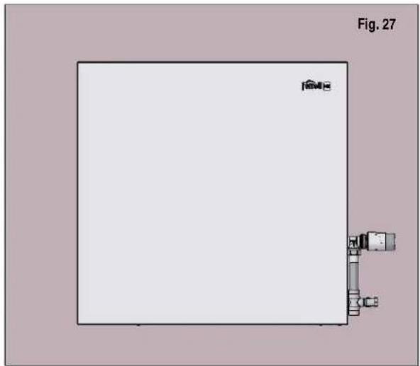
natural_image
Simple line drawing of a rectangular panel with internal components and no text or symbolsTWO-PIPE SYSTEMS
- Remove the clamps for transporting the heat exchanger (Fig.28), as well as the plugs from the upper and lower emitter sockets.
- Also remove the protective rubber plugs from the heat exchanger.
CAUTION: The battery is supplied at a pressure of 1.5 bar with nitrogen to ensure no leakage (Fig.28b).
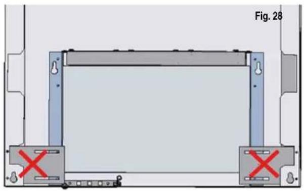
natural_image
Technical diagram showing a rectangular frame with two side supports and red X marks, labeled Fig. 28 (no text or symbols on the diagram itself)
natural_image
3D diagram of a mechanical component with four curved pipe fittings, labeled Fig. 28b (no text or symbols on the diagram itself)- Using the template provided on the back of the package, mark on the wall the anchoring points (2 locations) for the heat exchanger, taking into account the position of the water inlets (right or left). Also, check the position of the four attachment points of the outer cover, taking into account the measurement of the taps/valves/fittings to be used.
- Drill the holes carefully and insert a plug for each anchor point. We recommend using 8 mm diameter plugs.
- Position the heat exchanger.

natural_image
Illustration of a blue door lock with a metallic keyhole and handle (no text or symbols)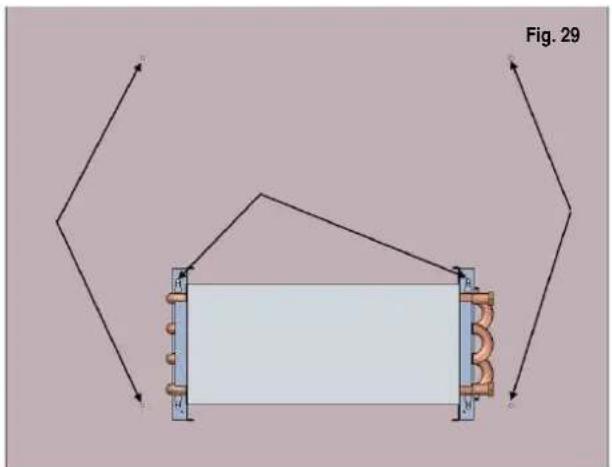
- Connect the valves, taps or fittings, leaving the assembly of the electro thermostatic valves until the end. The water inlet must ALWAYS be at the upper outlet.
- When water begins to fill the radiator, use the upper bleeder to remove air inside the heat exchanger
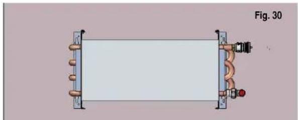
natural_image
Diagram of a rectangular device with coiled pipes and connectors, labeled Fig. 30 (no text or symbols on the diagram itself)- Position the outer cover.

natural_image
Simple line drawing of a door handle with a circular knob (no text or symbols)
natural_image
Technical diagram of a rectangular frame with copper coils and a light blue central block, labeled Fig. 31 (no text or symbols on the diagram itself)- Using a small rubber hammer, open the pre-drilled hole in the cover enough to make the electro thermostatic valve accessible.

natural_image
Technical diagram of a vertical panel with two circular holes, labeled Fig. 31 (no text or symbols on the diagram itself)
natural_image
3D technical illustration of a mechanical component with copper coils and a circular opening, labeled Fig. 32 (no text or symbols on the diagram itself)- Screw the thermostatic head and place the front. If the model has the HE system, place the cover caps in the front holes.

natural_image
Diagram of a door panel with a cylindrical component and two circular holes, labeled Fig. 33 (no text or symbols on the diagram itself)
natural_image
Blank white square with a small black square and label 'Fig. 34' above (no other text or symbols)HE SYSTEM CONNECTION
Models equipped with the HE system come pre-installed for the water inlet sockets on the right-hand side. If your installation requires inlet sockets on the left side, follow these points by order. Otherwise, skip to point 4:
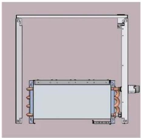
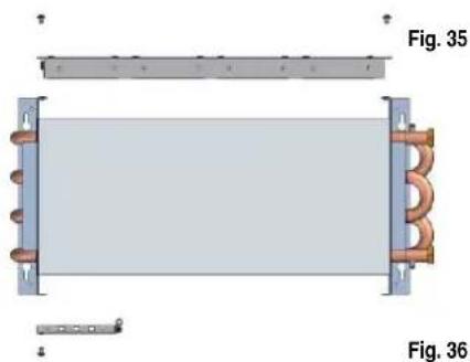
- Before mounting the core on the wall remove the four screws that support the fan HE KIT at the top (fig. 35).
- Also remove the ambient sensor support by removing its two screws (fig. 35).
- Turn the heat exchanger around by 180^ and position again the HE KIT and the ambient sensor in the same position, as is shown in figs. 36
- Attach the clip of the water detection sensor to the tubes as is shown in figs. 37 and 38, taking into account the position of the water inlet sockets to the right (fig 37) or left (fig. 38).
- Connect the HE KIT fan power cord. (fig 39).
- Connect the room temperature sensor: Fig. 40
- Plug in the power cord into 220/230v A.C. 50 Hz. The emitter is provided with an open cable gland so that the cable can be removed and be plugged into an outlet socket that is inside the cover (check current regulations).
natural_image
Technical diagram of a coiled copper coil component with two labeled views (Fig. 35 and Fig. 36), no text or symbols present.
natural_image
Pure electrical circuit lines without any symbols
natural_image
Technical illustration of two mechanical assembly steps showing pipe connection and coiled tubing (no text or symbols)
natural_image
3D mechanical assembly diagram showing a component with copper coils and a red circle highlighting a specific area, labeled Fig. 39 (no text or symbols on the diagram itself)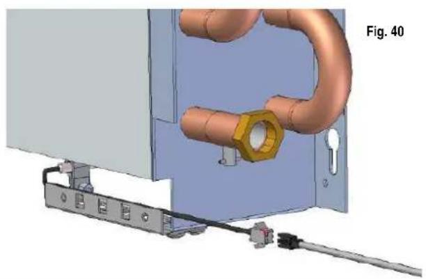
natural_image
3D mechanical assembly diagram showing pipe connection with a hexagonal bolt and connector (no text or symbols)
natural_image
Mechanical assembly diagram showing a component with a green control panel and red directional arrow (no text or symbols)HE SYSTEM OPERATION
GENERAL DESCRIPTION
- The HE system turns the VARESE emitter into a highly efficient apparatus by forcing air flow through the heat exchanger by using ultra silent brushless fans, electronically modulated by a processor connected to a room temperature sensor and another reading the water temperature of continuously entering water.
- This system is designed to operate completely autonomously and unattended from the first connection. Through the water inlet sensor, the system starts and stops automatically when the boiler or heat group is started or stopped.
- In addition, it uses all the heat stored in the emitter core even though the boiler or thermal unit has stopped. When the system detects that all the useful heat has been extracted, it will stop automatically.
GENERAL DESCRIPTION
- 2 touch-sensitive buttons that sound when pressed:
- Mode: alternative between modes. Each icon is backlit by LED when active. Tap this button to change the active mode emission.
- Stand-by: Force HE system shutdown. The red bar in the middle is backlit in red and blinks or unchanging to report a stand-by forced by the user or stand-by because of low temperature in the water inlet.

MODES
- Auto mode: with the room sensor, the system automatically modulates the emission capacity of the system. The word AUTO is backlit in blue in this mode

line
| ambient temperature | Speed fan | | ------------------- | --------- | | 0°C | high | | 0°C | med | | 17°C | low | | 20°C | min |• Eco Mode: Economic mode with lower emissions and almost negligible noise level. ECO icon back lit in green
• Comfort mode: average emission mode, suitable for normal boiler ignition: COMFORT icon back lit in red
- Boost mode: high performance mode. The emitter is at its maximum capacity issue. Recommended for situations of extreme cold or ignition after long periods of absence from the home. "Boost" icon backlit in red
• STAND-BY
• Automatic stand-by: When the system detects low temperature in the water inlet, it stops the fans and makes the red LED decreasingly blink. When it redetects hot water, it automatically goes into AUTO mode.
- Stand-by manual: The user turns off the system. The red LED remains fixed. Until you reactivate the system, the system will not go into any mode.
*NOTE: If you have turned on the boiler or the thermic group and its Varese HE emitter does not start automatically without being on stand-by manual mode, check that the holder or the thermostat tap installed is not closed completely.

flowchart
graph TD
    A["CONFORT"] --> B["ECO"]
    B --> C["AUTO"]
    C --> D["STAND-BY"]
    D --> E["BOOST"]
    E --> F["Ferroili"]
    style A fill:#f9f,stroke:#333
    style B fill:#ccf,stroke:#333
    style C fill:#cfc,stroke:#333
    style D fill:#fcc,stroke:#333
    style E fill:#ffc,stroke:#333
    style F fill:#cff,stroke:#333
ERROR MESSAGES
The HE system is ready to auto-detect malfunctions. To do so, the icons blink to report each error, as follows:
- AUTO mode blinking: error in the water detection sensor.
• STAND-BYr apid blinking: error in the ambient sensor. - AUTO mode and Stand By blinking: error in both sensors.
If any of these errors occur, contact the Ferroli Technical Service.
CLEANING AND MAINTENANCE
The VARESE / VARESE HE emitter does not require special maintenance, just occasional cleaning with a dry cloth (do not use chemical agents) of the outer cover.
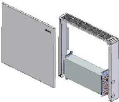
For heat exchanger and fans (VARESE HE models), proceed to remove the front as shown in the picture and remove the dust that may have accumulated on it using a duster or the similar.
CAUTION: The heat exchanger has thin and elongated aluminium surfaces to maximize heat transfer. Do not bend or damage them during cleaning as this can adversely affect the emissivity of the system

natural_image
3D rendering of an open industrial enclosure with internal battery pack (no text or symbols visible)Fig. 44
ELECTRIC DIAGRAM (HE MODELS)
Fig. 45

flowchart
graph LR
    A["230V AC"] --> B["AC/DC"]
    B --> C["Control"]
    C --> D["M1"]
    C --> E["M2"]
    C --> F["M3"]
    B --> G["L"]
    B --> H["N"]
    B --> I["S1"]
    B --> J["S2"]
    C --> K["+"]
    C --> L["-"]
    C --> M["12V CC"]
natural_image
3D rendering of an open industrial enclosure with a side panel and internal components (no text or symbols visible)natural_image
3D diagram of a device showing two views: one with a flat panel on the left and another with a rectangular housing on the right, both without any text or symbols.natural_image
3D rendering of an electronic device showing a rectangular housing with internal components and a separate open panel (no text or symbols visible)natural_image
3D rendering of an electronic device showing a panel with a shield and internal components (no text or symbols visible)natural_image
Front view of a rectangular industrial or mechanical component with attached pipes and connectors (no visible text or symbols)
natural_image
Technical illustration of a mechanical pipe fitting assembly (no text or symbols visible)natural_image
Technical line drawing of a rectangular enclosure with internal components and mounting brackets (no text or symbols)
natural_image
3D mechanical assembly diagram showing fan arrangement and pipe connection (no text or symbols)natural_image
Diagram of six cylindrical cells with arrows indicating direction, no text or symbols presentnatural_image
Diagram of a row of cylindrical containers with arrows indicating direction, no text or symbols presentnatural_image
Pure diagram of vertical cylindrical structures with arrows indicating direction, no text or symbols presentnatural_image
Technical line drawing of a large industrial cooling unit with coiled ducts and heat exchangers (no text or symbols)natural_image
Technical diagram showing a structural frame with red X marks indicating failure or absence, labeled Fig. 21 (no text or symbols on the diagram itself)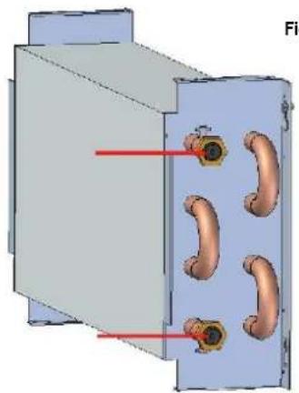
natural_image
3D diagram of a mechanical housing with four copper-colored pipes and red arrows indicating direction (no text or symbols)Fig. 21b
natural_image
Illustration of a blue door lock with a handle, no text or symbols visible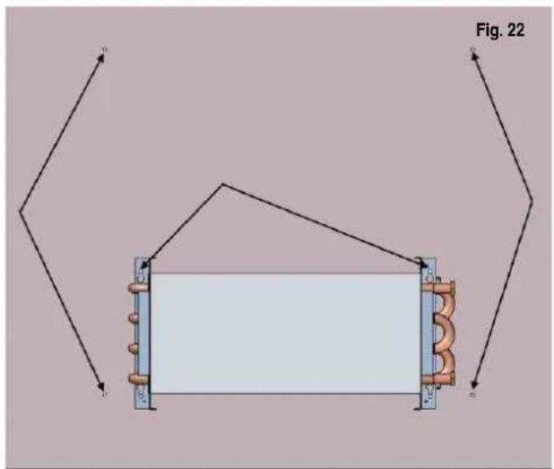

natural_image
Diagram of a rectangular frame with a central rectangular block and coiled elements, labeled Fig. 23 (no text or symbols on the diagram itself)natural_image
3D rendering of a door with two circular buttons and a knob (no text or symbols)natural_image
3D rendering of a vertical panel with two circular holes, shown in perspective view (no text or symbols)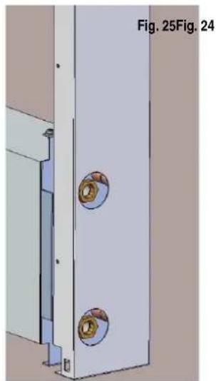
natural_image
3D CAD model of a vertical panel with two circular components, labeled Fig. 25 and Fig. 24 (no text or symbols on the panel itself)natural_image
Technical diagram of a mechanical assembly with spring-loaded components and frame structure (no text or symbols)natural_image
Pure diagram of a rectangular panel with internal components and no text or symbolsIMPIANTI BITUBO
natural_image
Technical diagram showing a rectangular frame with two mounting brackets and red X marks indicating failure or absence (no text or symbols present)
natural_image
3D diagram of a mechanical housing with four copper-colored pipes and two red arrows pointing to the side (no text or symbols)natural_image
Illustration of a blue door with a handle and circular opening, no text or symbols present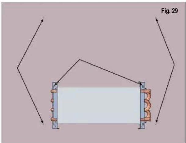
natural_image
Pure electrical circuit lines without any symbolsnatural_image
Close-up of a metallic door handle with a circular knob (no text or symbols visible)
natural_image
Technical diagram of a rectangular frame with copper coils and a central rectangular block, labeled Fig. 31 (no text or symbols on the diagram itself)natural_image
3D diagram of a vertical panel with two circular holes, labeled Fig. 31 (no text or symbols on the panel itself)
natural_image
3D mechanical assembly diagram showing a vertical panel with copper coils and a central circular component, labeled Fig. 32 (no text or symbols on the diagram itself)natural_image
Diagram of a door panel with a cylindrical component and a circular base, labeled Fig. 33 (no text or symbols on the diagram itself)
natural_image
Blank white rectangular panel with a small black corner detail, labeled 'Fig. 34' at top (no other text or symbols)natural_image
Technical diagram of a coiled copper coil component with two labeled figures (Fig. 35 and Fig. 36), no text or symbols present.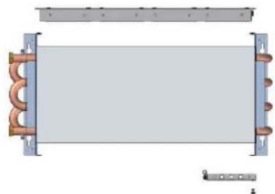
natural_image
Pure electrical circuit lines without any symbols
natural_image
3D CAD diagrams showing pipe installation in two views (Fig. 37 and Fig. 38), no text or symbols present.
natural_image
3D rendering of a heat exchanger or cooling unit with copper pipes and a red circle highlighting a component, labeled Fig. 39 (no text or symbols on the diagram itself)
natural_image
3D CAD rendering of a mechanical assembly with copper pipes, a hexagonal bolt, and wiring (no text or symbols)
natural_image
Mechanical assembly diagram showing a green control panel connected to a black cable, with a red arrow pointing to the component (no text or symbols visible)- Auto mode: with the room sensor, the system automatically modulates the emission capacity of the system. The word AUTO is backlit in blue in this mode

line
| temperature ambiente | Ventilazione fan | | -------------------- | ---------------- | | 0°C | high | | 0°C | med | | 17°C | high | | 17°C | med | | 20°C | high | | 20°C | min |natural_image
3D rendering of an open industrial enclosure with internal battery pack (no text or symbols visible)Fig. 44
SCHEMA ELETTRICO (MODELLI HE)
Fig. 45

flowchart
graph LR
    A["230V AC"] --> B["AC/DC"]
    B --> C["Control"]
    C --> D["M1"]
    C --> E["M2"]
    C --> F["M3"]
    B --> G["L"]
    B --> H["N"]
    B --> I["S1"]
    B --> J["S2"]
    C --> K["+"]
    C --> L["-"]
    C --> M["12V CC"]
CERTIFICADO DE GARANTIA


- CONEXION DEL SISTEMA HE
- ESQUEMA ELÉCTRICO ( MODELOS HE )
- PURPOSE
- VERSIONS AVAILABLE
- MAIN COMPONENTS
- COMPONENTS DESCRIPTION
- COMPONENT DESCRIPTION
- TYPES OF INSTALLATION SUPPORTED
- ONE-PIPE INSTALLATIONS
- TWO-TUBE INSTALLATION NEW CONSTRUCTION
- REPLACEMENT TWO-TUBE INSTALLATION
- DIMENSIONS
- POSITION OF HYDRAULIC CONNECTIONS
- ONE PIPE SYSTEMS
- TWO-PIPE SYSTEMS
- HE SYSTEM CONNECTION
- HE SYSTEM OPERATION
- GENERAL DESCRIPTION
- MODES
- ERROR MESSAGES
- CLEANING AND MAINTENANCE
- ELECTRIC DIAGRAM (HE MODELS)
- IMPIANTI BITUBO
- SCHEMA ELETTRICO (MODELLI HE)
- CERTIFICADO DE GARANTIA
Brand : FERROLI
Model : Varese
Category : Heating