BQ6332 - Barbecue Brixton - Free user manual and instructions
Find the device manual for free BQ6332 Brixton in PDF.
User questions about BQ6332 Brixton
0 question about this device. Answer the ones you know or ask your own.
Ask a new question about this device
Download the instructions for your Barbecue in PDF format for free! Find your manual BQ6332 - Brixton and take your electronic device back in hand. On this page are published all the documents necessary for the use of your device. BQ6332 by Brixton.
USER MANUAL BQ6332 Brixton
natural_image
Exterior view of a portable grill with open lid and black tray, accompanied by a pair of suitcases and a separate line drawing of a person's legs (no text or symbols)1006.332
Draagbare gasgrill
*Voor DK, FI, NO, NL, SE: I3B/P (30)
Butaan/Propaanmengsel: 30 mbar
Butaan: 28-30 mbar of Propaan: 37 mbar.
*Voor ES, IE, PT, GB: I3P(37)
Propaan: 37mbar
*Voor DE, AT: I3B/P (50)
Butaan /Propaanmengsel: 50 mbar
*Voor DE, NL, ES: I3P(50)
Propaan: 50 mbar
text_image
Exploded view diagram of a vehicle's internal components with numbered labels indicating parts like chassis, wheels, and suspension systems.natural_image
Close-up of hands using a tool to adjust or install a mechanical component, labeled 'FIG. 2' (no other text or symbols visible)
text_image
FIG. 3 Bottom Shelf Hook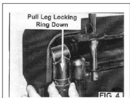
text_image
Pull Leg Locking Ring Down FIG 4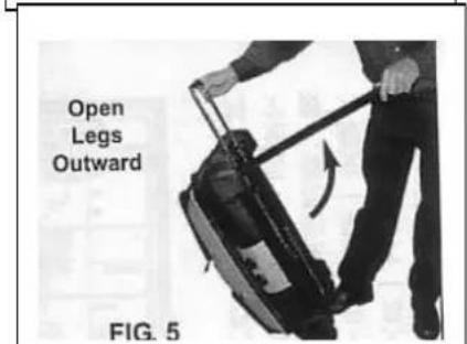
text_image
Open Legs Outward FIG. 5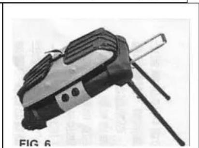
natural_image
Black and white photo of a handheld electronic device with a stand and three ports (no visible text or symbols)
natural_image
Person using a handheld device with a curved arrow indicating rotation (no text or symbols visible)
natural_image
Illustration of a portable grill with a cutaway view showing a blade being inserted into a pan (no text or symbols)
text_image
Leg Spring Lock FIG. 9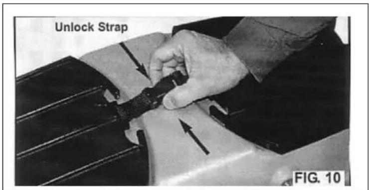
text_image
Unlock Strap FIG. 10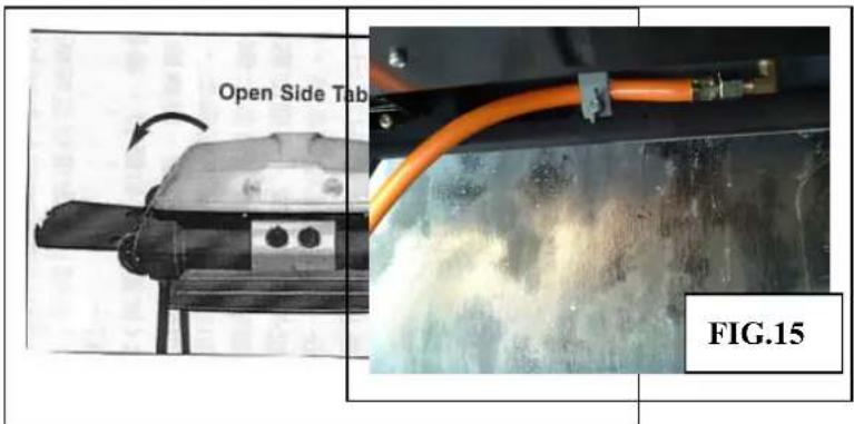
text_image
Open Side Tab FIG.15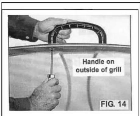
text_image
Handle on outside of grill FIG. 14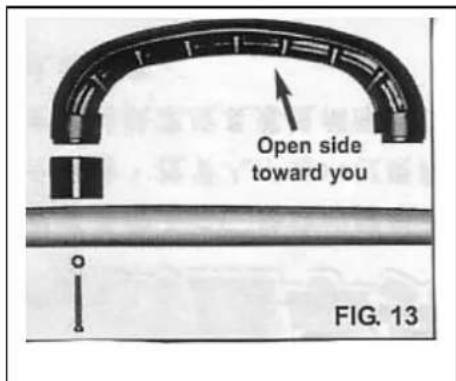
text_image
Open side toward you FIG. 13natural_image
Line drawing of a mechanical clamp or lever assembly (no text or symbols)b) Verstopte gasslang
text_image
FIG.20 7) Remove 5-Screws from Burner Brackets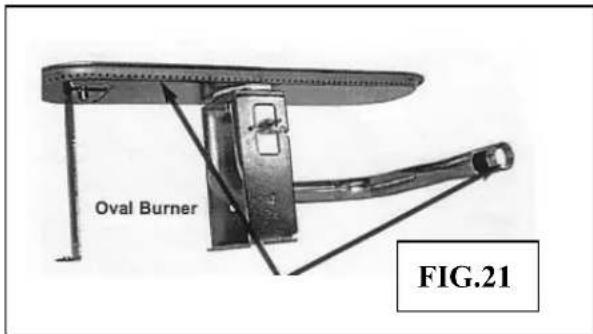
text_image
Oval Burner FIG.21*Pour DE, AT : I3B/P (50)
Mélange Butane /Propane : 50 mbars
*Pour DE, NL, ES : I3P(50)
Propane : 50 mbars
text_image
Exploded view diagram of a vehicle's internal components with numbered labels for identificationnatural_image
Close-up of hands assembling a mechanical component (no visible text or symbols)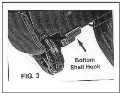
text_image
FIG. 3 Bottom Shelf Hook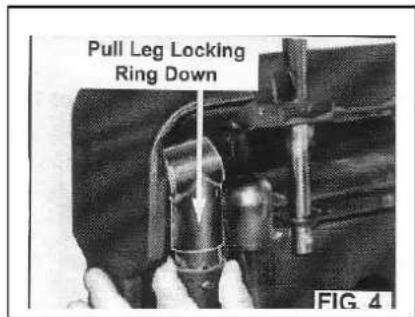
text_image
Pull Leg Locking Ring Down FIG. 4
text_image
Open Legs Outward FIG. 5
natural_image
Black-and-white photo of a handheld electronic device with a tripod handle and ventilation slots (no visible text or symbols)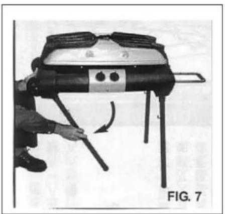
natural_image
Person operating a mechanical device with lever mechanism, labeled 'FIG. 7' (no text on device itself)
natural_image
Illustration of a portable grill with a coiled bed and a cutting board, showing a close-up of the tray (no text or symbols)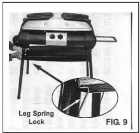
text_image
Leg Spring Lock FIG. 9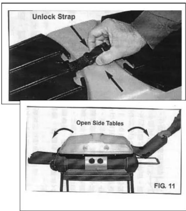
text_image
Unlock Strap Open Side Tables FIG. 11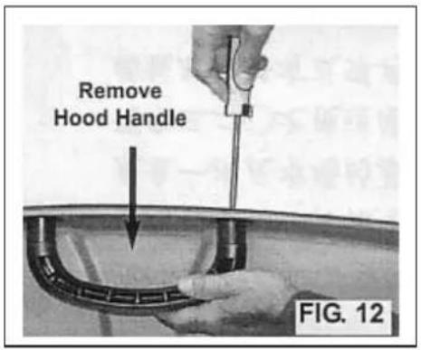
text_image
Remove Hood Handle FIG. 12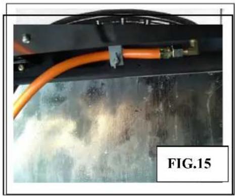
natural_image
Close-up of a mechanical component with orange tubing and connectors, labeled FIG.15 (no readable text or symbols on the main subject)
text_image
Handle on outside of grill FIG. 14natural_image
Line drawing of a hand holding a mechanical lever or valve (no text or symbols present)Figure 17
Option plaque chauffante
text_image
FIG.20 7) Remove 5-Screws from Burner Brackets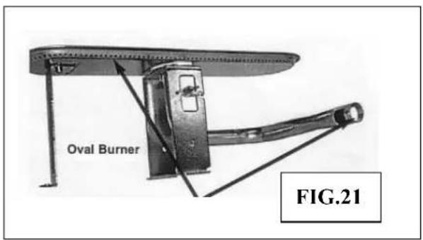
text_image
Oval Burner FIG.21*Für DK, FI, NO, NL, SE: I3B/P (30)
Butan/Propan-Gemisch: 30 mbar
Butan: 28-30 mbar oder Propan: 37 mbar.
*Für ES, IE, PT, GB: I3P(37)
Propan: 37mbar
*Für DE, AT: I3B/P (50)
text_image
Exploded view diagram of a vehicle's internal components with numbered parts for identificationtext_image
Pull Leg Locking Ring Down FIG 4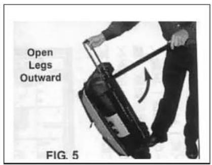
text_image
Open Legs Outward FIG. 5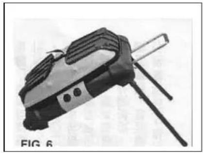
natural_image
Black and white photo of a handheld electronic device with a tripod handle (no visible text or symbols)
natural_image
Person operating a portable device with legs and handles, no visible text or symbols
natural_image
Illustration of a portable grill with a cutting board and a circular base, no text or symbols present
text_image
Leg Spring Lock FIG. 9
text_image
Unlock Strap FIG. 10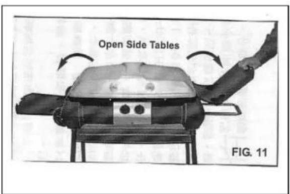
text_image
Open Side Tables FIG. 11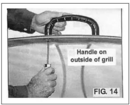
text_image
Handle on outside of grill FIG. 14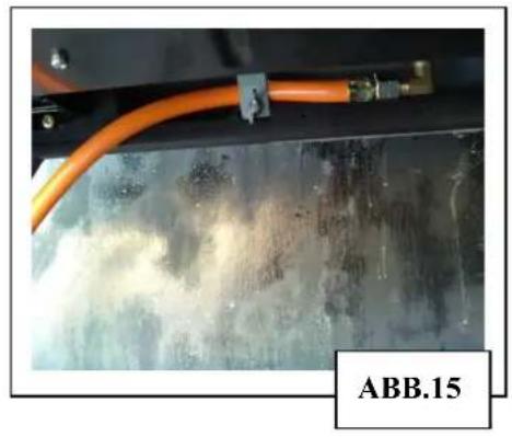
natural_image
Close-up of a metallic panel with orange tubing and a label 'ABB.15' (no readable text or symbols on the main subject)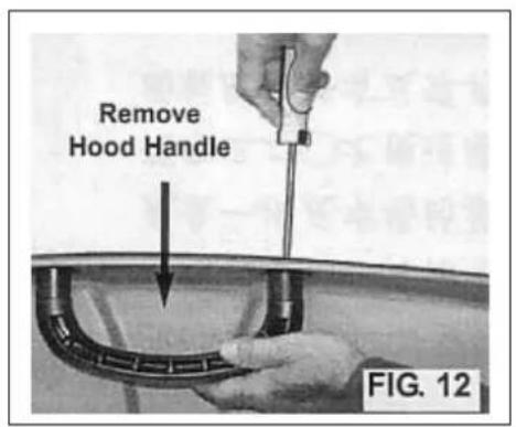
text_image
Remove Hood Handle FIG. 12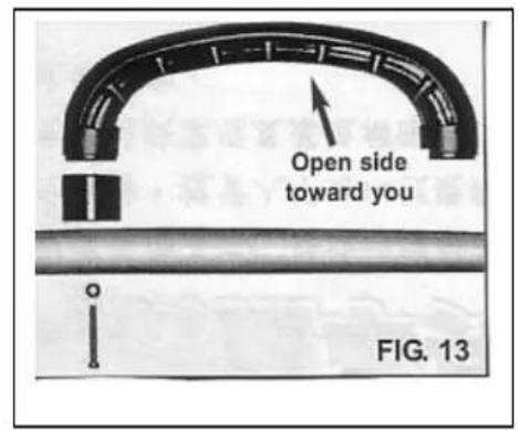
text_image
Open side toward you FIG. 13natural_image
Line drawing of a mechanical device with a handle and lever (no text or symbols)Abbildung 17
text_image
ABB.2 7) Remove 5-Screws from Burner Brackets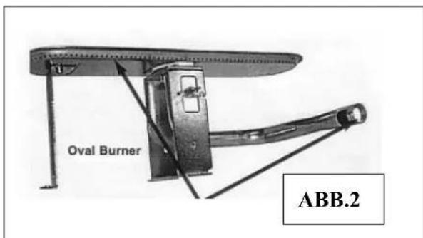
text_image
Oval Burner ABB.2IMPORTANT: Read these instructions for use carefully so as to familiarize yourself with the appliance before connecting its gas cylinder. Keep these instructions for future reference.
| Gas Category | I3+(28-30/37), I3B/P(30), I3P(37) | I3B/P(50), I3P(50) |
| Total Heat Input(kW) | 3.5kW(255 g/h G30) | 4.2 kW (255 g/h G30) |
| 3.5 kW (250 g/h G31) |
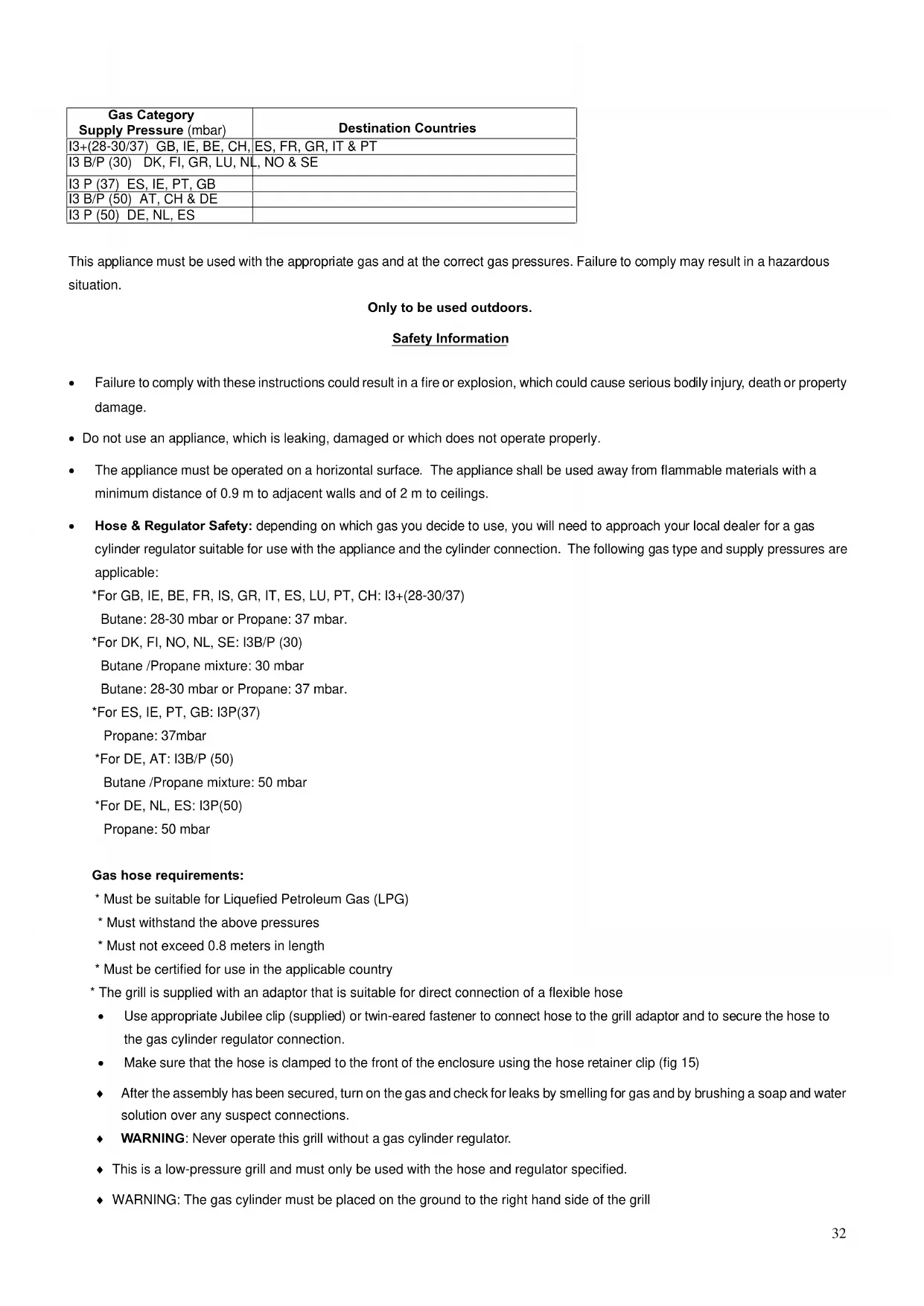
| Gas CategorySupply Pressure (mbar) | Destination Countries |
| I3+(28-30/37) GB, IE, BE, CH, | ES, FR, GR, IT & PT |
| I3 B/P (30) DK, FI, GR, LU, NL, NO & SE | |
| I3 P (37) ES, IE, PT, GB | |
| I3 B/P (50) AT, CH & DE | |
| I3 P (50) DE, NL, ES |
This appliance must be used with the appropriate gas and at the correct gas pressures. Failure to comply may result in a hazardous situation.
Only to be used outdoors.
Safety Information
- Failure to comply with these instructions could result in a fire or explosion, which could cause serious bodily injury, death or property damage.
- Do not use an appliance, which is leaking, damaged or which does not operate properly.
- The appliance must be operated on a horizontal surface. The appliance shall be used away from flammable materials with a minimum distance of 0.9 m to adjacent walls and of 2 m to ceilings.
- Hose & Regulator Safety: depending on which gas you decide to use, you will need to approach your local dealer for a gas cylinder regulator suitable for use with the appliance and the cylinder connection. The following gas type and supply pressures are applicable:
*For GB, IE, BE, FR, IS, GR, IT, ES, LU, PT, CH: I3+(28-30/37)
Butane: 28-30 mbar or Propane: 37 mbar.
*For DK, FI, NO, NL, SE: I3B/P (30)
Butane /Propane mixture: 30 mbar
Butane: 28-30 mbar or Propane: 37 mbar.
*For ES, IE, PT, GB: I3P(37)
Propane: 37mbar
*For DE, AT: I3B/P (50)
Butane /Propane mixture: 50 mbar
*For DE, NL, ES: I3P(50)
Propane: 50 mbar
Gas hose requirements:
* Must be suitable for Liquefied Petroleum Gas (LPG)
* Must withstand the above pressures
* Must not exceed 0.8 meters in length
* Must be certified for use in the applicable country
* The grill is supplied with an adaptor that is suitable for direct connection of a flexible hose
- Use appropriate Jubilee clip (supplied) or twin-eared fastener to connect hose to the grill adaptor and to secure the hose to the gas cylinder regulator connection.
• Make sure that the hose is clamped to the front of the enclosure using the hose retainer clip (fig 15)
After the assembly has been secured, turn on the gas and check for leaks by smelling for gas and by brushing a soap and water solution over any suspect connections.
♦ WARNING: Never operate this grill without a gas cylinder regulator.
- This is a low-pressure grill and must only be used with the hose and regulator specified.
♦ WARNING: The gas cylinder must be placed on the ground to the right hand side of the grill
- When connecting the hose and regulator assembly to the gas cylinder, take care to avoid unnecessary twisting of the flexible hose.
- Keep the gas hose away from hot surfaces. Protect the gas hose from dripping grease. Avoid unnecessary twisting of hose. Visually inspect the hose prior to each use for cracks, excessive wear or other damage. Replace the hose if necessary. Never test for leaks with a lit match or open flame, use soap and water solution. Never alter or modify the Regulator or gas supply assembly. This grill must not be used indoors.
♦ WARNING: accessible parts may be very hot. Keep young children away. - Keep children away from grill during use and until grill has cooled after you have finished. Do not allow children to operate grill.
♦ WARNING: Do not places combustible articles on the bottom shelf as it may become hot during operation of the grill.
◆ Any modifications of this appliance may be dangerous. - Do not move the appliance during use.
DO NOT use your grill in garages, porches, breezeways, sheds or other enclosed areas. Your grill is to be used OUTDOORS only. The grill is not intended to be installed in or on recreational vehicles and/or boats and should not be placed under any surface that will burn. Do not obstruct the flow of combustion and ventilation air around the barbecue housing.
◆ Always ensure that no sporting or physical activities are carried out in close proximity to the grill during use and while still hot.
Parts sealed by the manufacturer or the user must not manipulate their agent. This appliance is only to be used outdoors only.
If there is a leak on your appliance (smell of gas), take it immediately into a well-ventilated flame free location where the leak may be detected and stopped. Do not try to detect leaks using a flame, use soapy water. Do not use the appliance until the leak has been stopped. -
After the assembly has been secured, turn on the gas and check for leaks by brushing a soap and water solution over all the gas connections.
♦ WARNING: Do not test for Gas leaks with a naked flame.
If you are unable to correct the leak by tightening the connections, turn off the gas and contact your supplier immediately.
♦ WARNING: If you smell gas -
Shut off gas to the grill at gas cylinder valve
- Extinguish any open flame.
- Raise the lid.
- If the odor continues immediately call your supplier or fire department if it is a serious leak from the gas cylinder.
♦ Turn off gas supply at the gas cylinder after use.
The appliance can be stored indoors once disconnected from the gas cylinder. The gas cylinder must be stored outdoors in a well-ventilated area.
When changing over from an empty gas cylinder to a full, make sure this procedure is carried out in a flame free atmosphere.
♦ WARNING: Do not store a spare gas cylinder under or near this grill. This grill is only to be used outdoors.
WARNING: Never store your gas cylinder indoors. If you store your grill indoors, ALWAYS disconnect the gas cylinder first and store the cylinder safely outside. Cylinders must be stored outdoors in a well-ventilated area out of reach of children, and must not be stored in a building, garage any other enclosed area.
Do not store or use petrol or other flammable liquids in the vicinity of this or any other appliance.
text_image
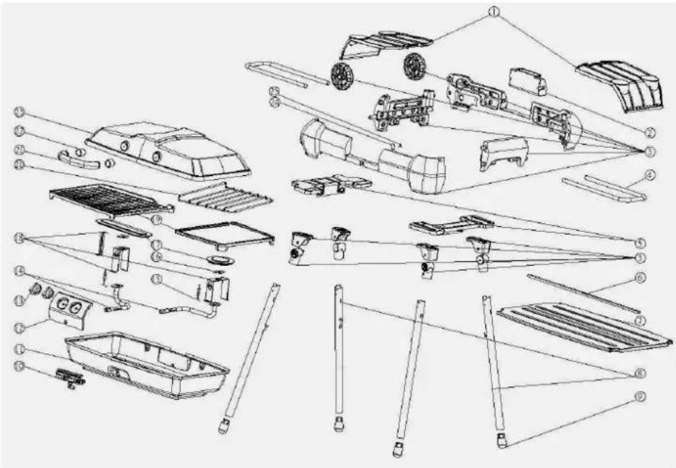
Exploded view diagram of a vehicle's internal components with numbered parts for identification-
Side Table 14. Orifice Tube
-
Drip Tray 15. Electrode Assembly
-
Enclosure
-
Burner Gasket
-
Right Side Handle
-
Left and Right Hand Burners
-
Enclosure 18. Burner Support
-
Side Table Retainer 19. Grill Plate
-
Bottom Shelf 20. Pan Support
-
Stand 21. Lid Handle
9 Feet
-
Lid Handle Spacer
-
Gas Tap Assembly 23. Lid
-
Grill Base
-
Hose retainer clip
-
Control Panel
-
Screw
-
Control Knob
Preparation and Grill Set-up
Before First Use: Remove Grill and all the packing from carton and place on the floor. Make sure there are no loose parts. Note: Before using your grill, read these instructions.
Follow instructions of each step in the order they are written as you look at the diagrams. This will allow for easier assembly.
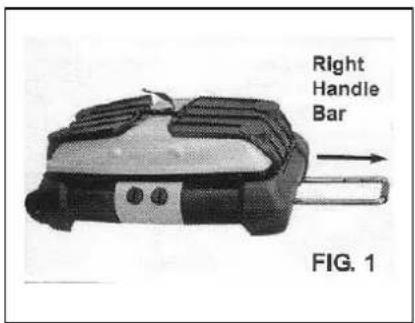
STEP 1. With the Grill on the floor or a level surface, pull the Right Handle Bar all the way out (there are three positions) until it clicks into place. (Fig. 1)
STEP 2. Lift the grill to the upright position so that it rests on its wheels by pulling on the right handle and tilting the base against your foot or leaning it against a wall. Remove the bottom shelf by pulling it away from the snap locks at the top of the enclosure (Fig. 2) and lifting it out of the Shelf supports at the bottom of the enclosure. (Fig.3) Place the shelf to one side
STEP 3. Unfold the front right and rear right legs by pulling downward on the spring loaded locking rings at the top of each leg (Fig. 4) and swinging the legs out and away from the grill until they lock into place. (Fig. 5)
STEP 4. Lean the Grill on the right hand side legs. (Fig. 6) Lift up the left hand side of the Grill, then unfold the front left and rear left legs by pulling downward on the spring loaded locking rings and swinging the legs out and away from the grill until they lock into place. (Fig. 7)
STEP 5. Position the bottom shelf by hanging it on the shelf hooks on the right hand side legs (Fig. 8) and pushing the other end over the locking springs on the left hand side legs so that the shelf snaps into position. (Fig. 9)
STEP 6. Position the side shelves by firstly unlocking the fastening strap by squeezing the catch (fig 10), then Pull out the Left handle bar fully and fold down both Side Tables. (Fig. 11)
STEP 7. Open the lid. With a Screwdriver, remove the lid Handle from the inside of the lid. (Fig. 12) With the same screws, carefully align the Metal Spacers and Handle. (Fig. 13) Be sure the open side of the handle points toward you as you install it. Assemble the Handle on the outside of the lid (Fig. 14).
Step 8. Attach hose retainer clip to fix the hose. (Fig. 15)
text_image
Right Handle Bar FIG. 1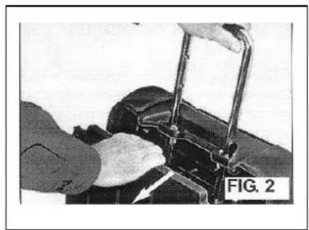
natural_image
Close-up of hands operating a mechanical device with metal rods (no visible text or symbols)
text_image
FIG. 3 Bottom Shelf Hook
text_image
Pull Leg Locking Ring Down FIG. 4
text_image
Open Legs Outward FIG. 5
natural_image
Black and white photo of a handheld electronic device with three legs and a handle, labeled 'FIG. 6' (no readable text or symbols on the device itself)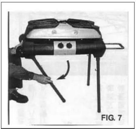
natural_image
Person using a handheld device with a curved arrow indicating motion (no text or symbols visible)
natural_image
Illustration of a portable grill with a cutting board and a saw, showing a close-up of the blade (no text or symbols)
text_image
Leg Spring Lock FIG. 9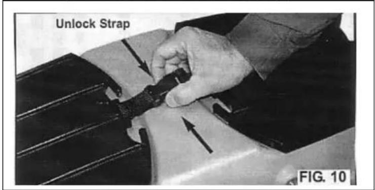
text_image
Unlock Strap FIG. 10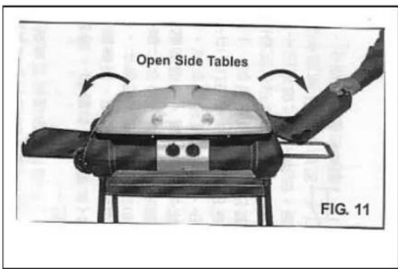
text_image
Open Side Tables FIG. 11
text_image
Remove Hood Handle FIG. 12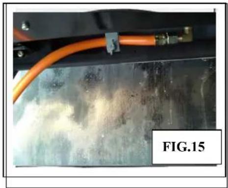
natural_image
Close-up of a mechanical component with orange tubing and a label 'FIG.15' (no readable text or symbols on the main subject)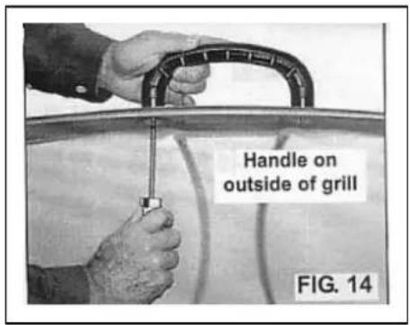
text_image
Handle on outside of grill FIG. 14WARNING: Never connect an unregulated gas cylinder to your barbecue.
Connecting the Gas Cylinder
IMPORTANT: Before connecting and disconnecting the barbecue to a gas cylinder make sure both of the grill control knobs are in the OFF position.
CAUTION: When the barbecue is not in use, the gas must be turned off at the gas cylinder valve.
Connecting:
• Make sure cylinder valve is closed.
- Check cylinder valve features to ensure it has proper mating threads to those of the regulator. Read the instructions supplied with the regulator to make sure of the correct connection and operation
• Make sure both of the grill burner control knobs are in the "OFF" position.
- Inspect cylinder valve connections port and regulator assembly. Look for any damage or debris. Remove any debris. Inspect hose for damage. Never attempt to use damaged or blocked equipment.
- Connect the regulator assembly to the cylinder valve.
- Open the cylinder valve fully. Use a soapy water solution to check all connections for leaks before attempting to light barbecue. If a leak is found, turn the cylinder valve off and do not use the grill until your local gas dealer can make repairs.
Disconnecting
○ Make sure both burner control valves are in the "OFF" position.
○ Make sure gas cylinder valve is fully closed.
- Detach the regulator assembly from gas cylinder valve.
Lighting Procedure
Ignition System Check
- The ignition test is done with the gas cylinder valve closed.
• Test both burners in turn detailed below
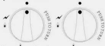
• Make sure the control knob is in the off position. Push
in and turn the control knob anti-clockwise through the
text_image
RUSH TO TURN RUSH TO TURNby following the procedure
Figure 16
ignition position ✗ to the High position until the control clicks.

- Repeat this operation, each time checking for a spark at the burner. If spark is not evident at the burner, check that the ignition lead is firmly attached to the control and spark electrode. With sparking established turn the Control Knob to the OFF position.
Note: If the igniter is faulty the burners can be lit using a lighted match attached to the match holder.
Burner Operation
- Open the lid before attempting to light the burners.
- The User should always operate the grill with the Drip Tray in place.
■ Make sure both the control knobs are in the Off • position. - Open the gas cylinder valve.
- To light the burners Push and in and turn the appropriate control knob anti-clockwise through the ignition position √ to the High
position ⚙, at the same time check that the burner has lit. See note below. The left hand control knob controls the left hand side burner and the right hand side control knob controls the right hand burner
- Once the burner has lit turning the control knob the low position can reduce the temperature of the grill
- To turn the burner off, turn the control knob fully clockwise to the off position •
- Turn off the gas cylinder valve when the grill is not in use.
Notes:
- Upon first assembly, the gas line and burners will be full of air. In order for the burners to light properly the lines must fill with gas. It may require several attempts at lighting the burners before you are successful. If a burner fails to light after several attempts turn off gas supply at cylinder and read "If the Barbecue Fails to Operate Properly" section below.
- Note if an igniter is faulty the burner can be lit using a lighted match attached to the match holder.
If the Barbecue Fails to Operate Properly
- Turn off the gas at the cylinder valve and turn both control Knobs to the OFF position.
◆ Wait 5 minutes before trying to light again.
◆ Check gas supply connections.
- Repeat the lighting procedure and if barbecue still fails to operate properly, turn off the gas at the cylinder valve and turn both control Knobs to the OFF position and wait for grill to cool and check the following:
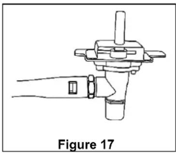
d) Misalignment of burner tube over orifice
CORRECTION: Reposition burner tube to properly sit over orifice as shown in Fig. 17.
b) Obstruction in gas hose
CORRECTION: Remove the hose from grill. DO NOT SMOKE! Open the gas cylinder valve for one second to blow any obstruction from the hose. Turn off the gas cylinder valve before reconnecting the hose to the grill.
natural_image
Line drawing of a mechanical device with a handle and lever, labeled Figure 17 (no text or symbols on the diagram itself)Operating Procedure
Burn-off
Before cooking on your grill for the first time, burn-off any residual oils or foreign matter by igniting the burners.
Ensure the lid is open and operate both burners at "High" setting for approximately 2-3 minutes. You may then turn the control valves to "OFF" or proceed to cooking at the "LOW" or "High" settings.
Preheating
It is necessary to preheat the barbecue for a short time before cooking certain foods, depending on the type of food and the cooking temperature. Food that requires a high cooking temperature, needs only a period of 5-6 minutes preheating.
Note: Do not close lid on the Grill Plate for more than 8 minutes, or without food loaded on the Grill Plate. The non-stick coating may be damaged.
Hotplate option
The right hand burner can be used as a hotplate for use with pans by removing the right hand side grill plate and replacing it with the "Pan support" rack. Do not cook food directly on the pan support, it must only be used when cooking with a pan.
Care & Maintenance
CAUTION: The lid must be in the open position for lighting.
Do not smoke at any time when attempting to ignite the grill burners.
Do not move the stand while the grill is in operation.
Do not leave the grill unattended when alight.
CAUTION: Beware of spiders and wasps. Burner tube should be inspected and cleaned periodically.
Care & Maintenance
As with all appliance, proper care and maintenance will keep them in top operating condition and prolong their life. Your new gas grill is no exception. By following these cleaning procedures on a timely basis, your grill will be kept clean and working properly with minimum effort.
Spiders and small insects occasionally spin webs or make nests in the burner tubes during warehousing and transit. These webs can lead to a gas flow obstruction that could result in a fire in and around the burner tubes.
This type of fire is known as “FLASH-BACK” and cause serious damage to your barbecue and create an unsafe operating condition for the user. Although an obstructed burner tube is not the only cause of “FLASH-BACK” it is the most common cause and frequent inspection and cleaning of the burner tube is necessary.
Flash-Back
If fire occurs in and around the burner, immediately turn off gas at the cylinder valve and turn the control knobs to the OFF position, wait until the grill has cooled, then clean the burner tubes and burner ports as described below.
Cleaning the Burner Tubes
In order to clean the inside of the burner tubes, the Burner Assembly must be removed from the grill. Make sure the gas cylinder, Grill Plates, Drip Tray and Leg Shelf have been removed before proceeding.
• Make sure the Grill Control Knobs are turned to the "OFF" position, and the grill has completely cooled.
- Disconnect the LP cylinder.
• Pull the Control Knobs off the valve stems. Remove the Control Panel and screws securing it.
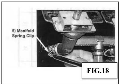
- Remove Spring Clips with screwdriver. (Fig.18)
- Remove the electrode Spring Clip by holding end of clip with pliers and pushing down away from the notch in burner bracket. (Fig. 19) Hold spring with fingers so clip dose not flip away.
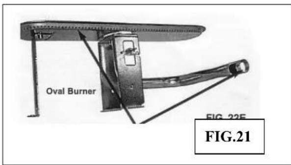
- Turn the grill upside down. Remove the screws holding the Burner Brackets from the bottom side. (Fig.20)
- Remove both Burner Assemblies from the grill.
- Use a pipe cleaner to clear obstructions from the Burner holes and inlet hole. (Fig.21) Verify that there are no insects or insect nests blocking the inlet hole. Normal wear and corrosion may enlarge some holes, however, if large cracks or holes are found the Burners should be replaced.
- After cleaning, re-assemble Burner Assemblies and other parts in reverse order of previous Steps 2-9 disassembly. Note: When refitting the Burners, be sure to check they are positioned correctly with the valves.
- Check burner operation after reassembly or cleaning.
- Clean the outside of the Burner Assembly with a paper towel or damp sponge. Open any clogged holes with a thin wire.
text_image
5) Manifold Spring Clip FIG.18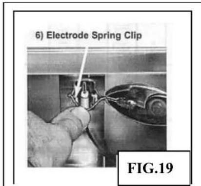
text_image
6) Electrode Spring Clip FIG.19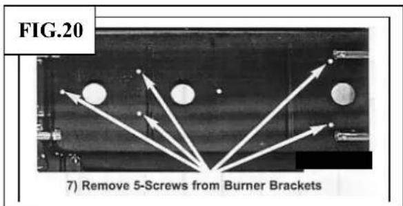
text_image
FIG.20 7) Remove 5-Screws from Burner Brackets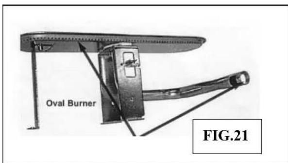
text_image
Oval Burner FIG.21Cleaning the Grill Plates
After cooking, turn both burner controls to the OFF position and let the grill cool before attempting to clean the grill plates. Before first use and periodically, it is suggested that the grill plates are washed using warm mild soapy water and a cleaning cloth
Care of Cooking Surface
Use and care of the cooking surface is important. Do not use metal utensils or cut food on the cooking surface. Use only plastic cooking utensils. Do not use pans on the grill plate cooking surfaces. Do not overheat the cooking surfaces with the lid down or without food being cooked.
Cleaning the Drip Tray
The drip tray should be emptied and wiped clean periodically and washed in warm mild soapy water.
General Maintenance and Repair
Do not modify the appliance.
After sales service
The appliance isn't user-serviceable. If it's not working properly, check that you've followed the instructions correctly.
If it still doesn't work, consult your retailer. If your retailer fails to solve your problem, ring the Customer Service Department.
If you need to return the grill to us:
- Disconnect the gas cylinder.
- Pack the grill carefully.
- Enclose your name, address, and daytime telephone number.
- Tell us what's wrong with it. If it's under guarantee, state where and when it was bought, and include proof of purchase (e.g. till receipt).
- Send it to Customer Service Dept, at the address at the end of this leaflet.
- They'll give you an estimate for inspection/repair.
Guarantee
Any defect affecting the functionality of the appliance which becomes apparent within 2 years of its purchase will be corrected by free repair or replacement provided that it has been used and maintained in accordance with the instructions and has not been abused or misused in any way. Your statutory rights are not affected. In line with our policy of continuous product development we reserve the right to change product, packaging and documentation specifications without notice.
***
*Per DK, FI, NO, NL, SE: I3B/P (30)
*Per DE, AT: I3B/P (50)
text_image
Exploded view diagram of a vehicle's internal components with numbered parts and exploded viewstext_image
Open Legs Outward FIG. 5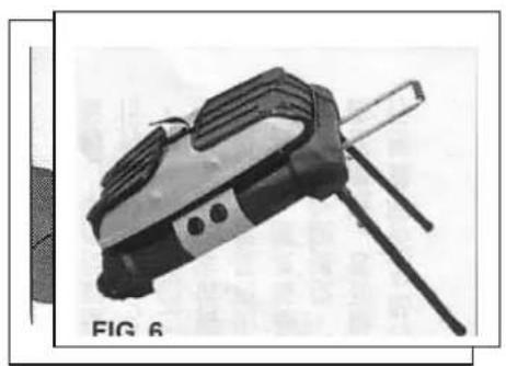
natural_image
Illustration of a handheld electronic device with a lever and screen (no text or symbols visible)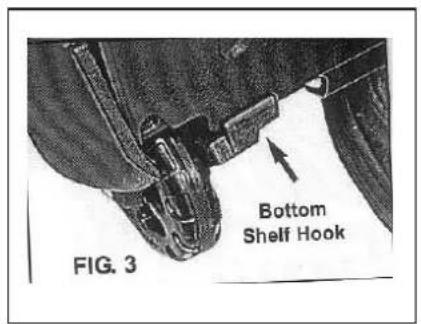
text_image
FIG. 3 Bottom Shelf Hook
text_image
Pull Leg Locking Ring Down FIG. 4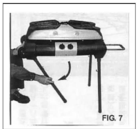
natural_image
Person operating a mechanical device with lever and handle, labeled 'FIG. 7' (no text on device itself)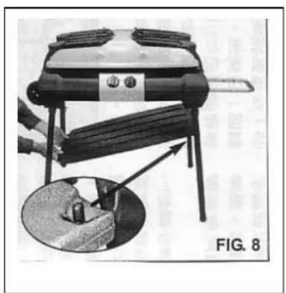
natural_image
Illustration of a portable grill with a cutaway view showing a lid and handle (no text or symbols)
text_image
Unlock Strap FIG. 10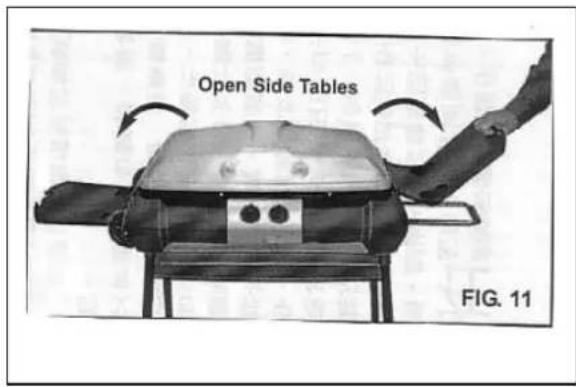
text_image
Open Side Tables FIG. 11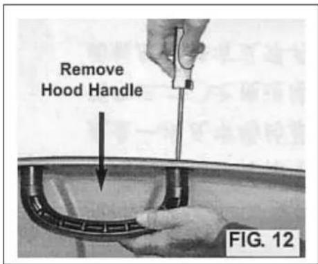
text_image
Remove Hood Handle FIG. 12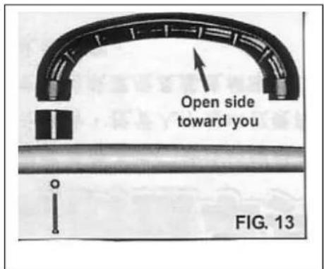
text_image
Open side toward you FIG. 13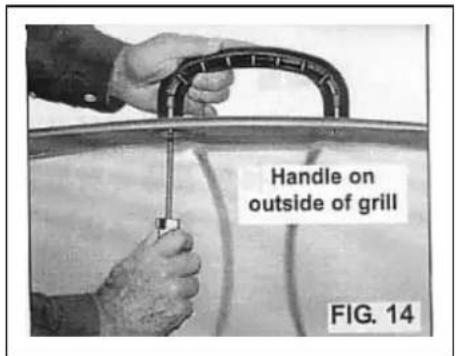
text_image
Handle on outside of grill FIG. 14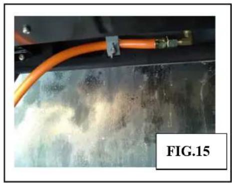
natural_image
Close-up of a mechanical component with orange tubing and a yellow connector, labeled 'FIG.15' (no readable text or symbols on the main subject)natural_image
Line drawing of a mechanical device with a handle and lever (no text or symbols)b) Tubo flessibile del gas intasato
text_image
FIG. 20 7) Remove 5-Screws from Burner Brackets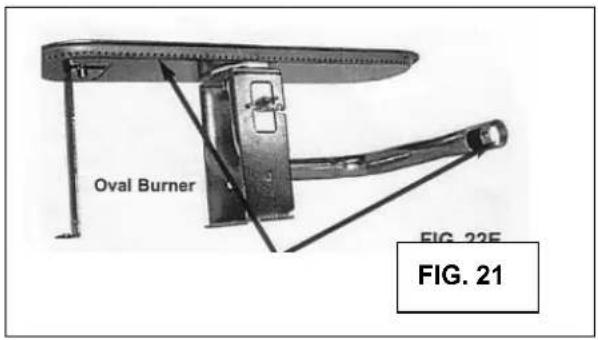
text_image
Oval Burner FIG. 22E FIG. 21*Para DK, FI, NO, NL, SE: I3B/P (30)
*Para DE, AT: I3B/P (50)
text_image
Exploded view diagram of a vehicle's internal components with numbered labels for identification.natural_image
Person operating a mounted device with a lever and handle, labeled 'FIG. 7' (no readable text or symbols on the device itself)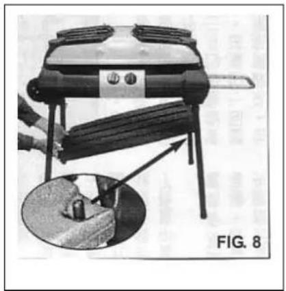
natural_image
Illustration of a grater with a handle and base, showing a close-up of its contents (no text or symbols)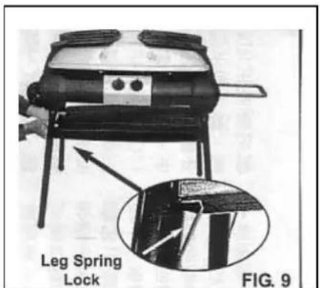
text_image
Leg Spring Lock FIG. 9
text_image
Unlock Strap FIG. 10
text_image
Open Side Tables FIG. 11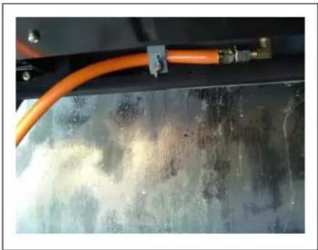
natural_image
Close-up of a mechanical pipe with orange tubing against a textured metallic surface (no visible text or symbols)
text_image
Remove Hood Handle FIG. 12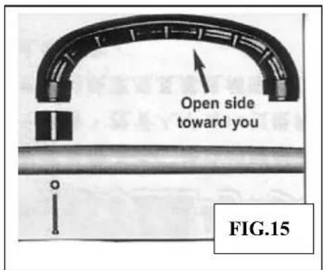
text_image
Open side toward you FIG.15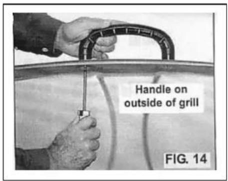
text_image
Handle on outside of grill FIG. 14natural_image
Line drawing of a mechanical device with a handle and lever, labeled 'Figura 17' (no other text or symbols)text_image
FIG.20 FIG. 22D 7) Remove 5-Screws from Burner Brackets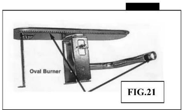
text_image
Oval Burner FIG.21*Para DK, FI, NO, NL, SE: I3B/P (30)
*Para DE, AT: I3B/P (50)
text_image
Exploded view diagram of a vehicle's internal components with numbered labels for identification.natural_image
Close-up of hands assembling a mechanical component with a metal bracket (no visible text or symbols)
text_image
FIG. 3 Bottom Shelf Hook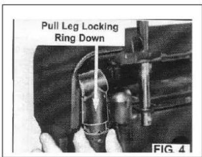
text_image
Pull Leg Locking Ring Down FIG. 4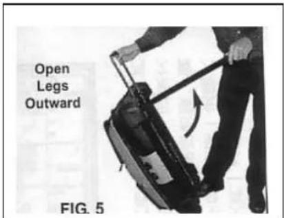
text_image
Open Legs Outward FIG. 5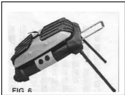
natural_image
Black and white photo of a handheld electronic device with a handle and three legs (no visible text or symbols)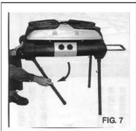
natural_image
Person assembling a mechanical device with lever mechanism (no visible text or symbols)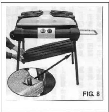
natural_image
Illustration of a portable grill with a handle and a close-up view of its contents, labeled 'FIG. 8' (no text on main subject)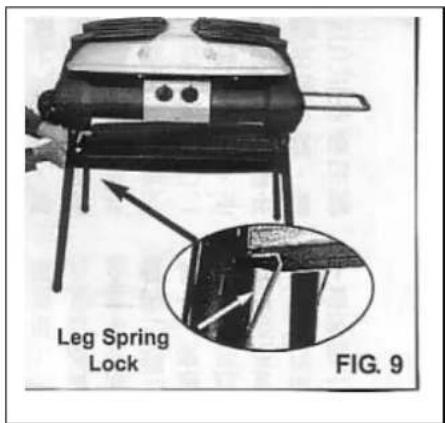
text_image
Leg Spring Lock FIG. 9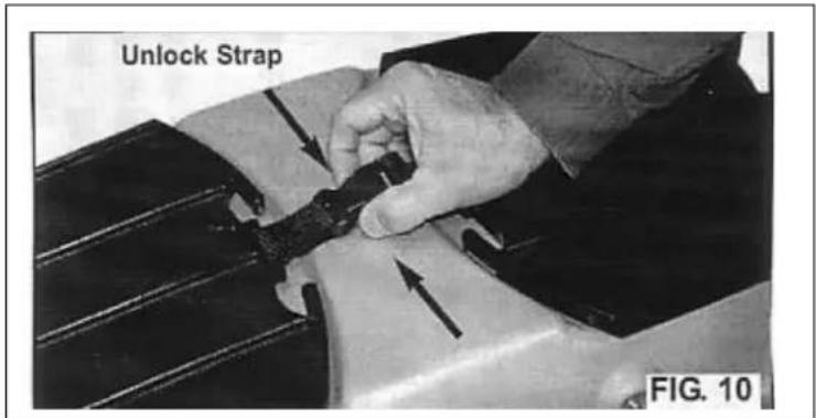
text_image
Unlock Strap FIG. 10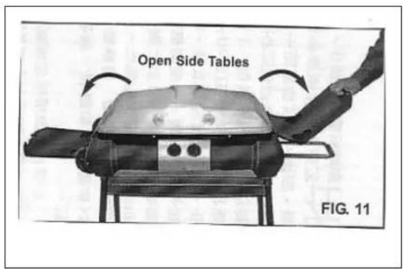
text_image
Open Side Tables FIG. 11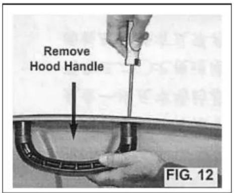
text_image
Remove Hood Handle FIG. 12
text_image
Open side toward you FIG. 13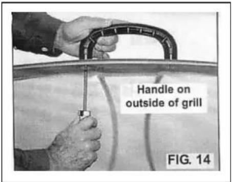
text_image
Handle on outside of grill FIG. 14
natural_image
Close-up of a metal panel with orange tubing and flanged connectors, showing dust or corrosion (no text or symbols visible)natural_image
Line drawing of a mechanical component labeled Figura 17, showing a lever and shaft assembly (no text or symbols on the diagram itself)text_image
FIG.20 7) Remove 5-Screws from Burner Brackets