YP 192.C50 - Cooker FRATELLI ONOFRI - Free user manual and instructions
Find the device manual for free YP 192.C50 FRATELLI ONOFRI in PDF.

User questions about YP 192.C50 FRATELLI ONOFRI
0 question about this device. Answer the ones you know or ask your own.
Ask a new question about this device
Download the instructions for your Cooker in PDF format for free! Find your manual YP 192.C50 - FRATELLI ONOFRI and take your electronic device back in hand. On this page are published all the documents necessary for the use of your device. YP 192.C50 by FRATELLI ONOFRI.
USER MANUAL YP 192.C50 FRATELLI ONOFRI
INSTRUCTIONS BOOKLET
GB
AVERTISSEMENTS POUR L'ENVIRONNEMENT
Déchets emballage

natural_image
Line drawing of a drawer with an arrow pointing to a slot, marked with a star (no text or symbols)TABLE DE CUISSON VITROCERAMIQUE
natural_image
Five identical line drawings of a pot with crossed panes, no text or symbols presentUTILISATION DU FOUR ELECTRIQUE
Convection naturelle
text_image
R P F L A G Fig. 3natural_image
Crossed black-and-white diagram showing a hand holding a tool above two circular patterns (no text or symbols)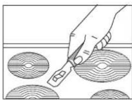
natural_image
Hand using a tool to cut circular patterns on a surface (no text or symbols visible)natural_image
Line drawing of a hand using a tool to lift a wall-mounted panel, with an arrow indicating direction (no text or symbols)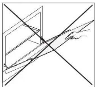
natural_image
Pure geometric lines forming a cross and diagonal construction (no text or symbols)Fig. 7 A
PORTE DU FOUR
natural_image
Line drawing of a two-door oven with control knobs and doors, labeled 'A' at the bottom (no text or symbols on the device itself)natural_image
Line drawing of a double boiler with two doors and control knobs, shown with a 1000-unit dimension label (no text or symbols on the diagram itself)mod. 108 (h = 900)
text_image
600 765 B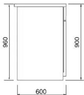
text_image
960 900 600AVERTISSEMENTS
natural_image
Technical line drawing of a rectangular frame with directional arrows indicating movement or force (no text or symbols)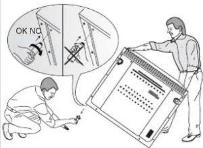
text_image
OK NOFig. 8 A
text_image
REG. MAX 15mmBRANCHEMENT ELECTRIQUE
BRANCHEMENT ELECTRIQUE
text_image
F L I H GREPLACEMENT DU CABLE
text_image
Technical diagram of an electrical switchgear with numbered components and labeled partsENTRETIEN DE L'APPAREIL
AVERTISSEMENTS
WAARSCHUWINGEN MET BETREKKING TOT DE OVEN:
natural_image
Line drawing of a drawer with an arrow pointing to one pan, marked with asterisk (no text or symbols)GLASKERAMISCHE KOOKPLAAT
natural_image
Five line drawings of cooking pots with crossed lines, showing different shapes and actions (no text or symbols)text_image
R P F L A G Fig. 3natural_image
Diagram showing a hand holding a tool crossed out by a black X mark over a patterned surface (no text or symbols)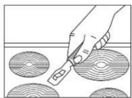
natural_image
Hand using a tool to cut circular patterns on a surface (no text or symbols visible)INTERNE GLAS
natural_image
Line drawing of a hand using a ruler to measure an angle, with an arrow indicating direction (no text or symbols)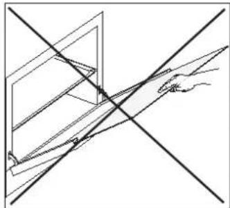
natural_image
Pure geometric lines forming a cross and diagonal construction (no text or symbols)Fig. 7 C
OVENDEUR
natural_image
Line drawing of a two-door electric oven with control knobs and doors, labeled 'A' at the bottom (no text or symbols on the diagram itself)A = 895 (mod. 192)
A = 1000 (mod. 108)
B = (h 115 / 165) - (h 100 / 150) (AFHANKELIJK VAN DE MODELLEN)
text_image
600 765 B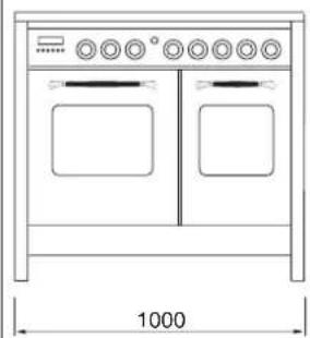
natural_image
Line drawing of a standard 1000-inch oven with two doors and control knobs (no text or symbols)mod. 108 (h = 900)
text_image
960 900 600WAARSCHUWINGEN
text_image
REG. MAX 15mmFig. 8A
text_image
Technical diagram of an electrical switchgear with numbered components and labeled partsONDERHOUD VAN HET TOESTEL
WAARSCHUWINGEN
natural_image
Diagram of a printer or printer holder with a curved arrow indicating rotation (no text or symbols present)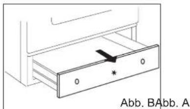
natural_image
Line drawing of a drawer with an arrow pointing to a slot, labeled Abb. A (no text or symbols on the diagram itself)GEBRAUCH DER KOCHMULDE
GLASKERAMIK-KOCHFELD
natural_image
Five line drawings of cooking pots with crossed x-marks, one emitting steam (no text or symbols)GEBRAUCH DER KOCHMULDE
text_image
R P I F L A G Abb. 3natural_image
Symbolic illustration of a hand holding a tool crossed over a patterned surface (no text or symbols present)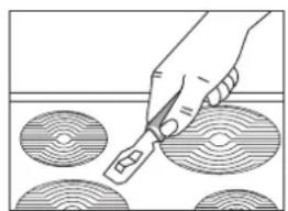
natural_image
Illustration of a hand using a tool to cut circular patterns on a surface (no text or symbols)Glasscheibe
natural_image
Line drawing of a hand using a tool to cut or extend a rectangular object, with an arrow indicating direction (no text or symbols)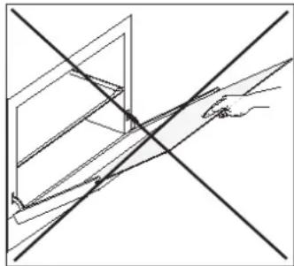
natural_image
Pure technical line drawing of intersecting diagonal lines and a hand holding a triangular object (no text or symbols)Abb. 7 A
BACKOFENTÜR
natural_image
Simple line drawing of a ladder leaning against a vertical wall, with an arrow indicating motion direction (no text or symbols)BACKOFEN
natural_image
Line drawing of a two-door electric oven with control knobs and doors, labeled A (no text or symbols on the device itself)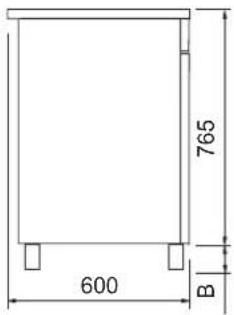
text_image
765 600 BA = 895 (mod. 192)
A = 1000 (mod. 108)
B = (h 115 / 165) - (h 100 / 150)(JE NACH MODELL)
natural_image
Line drawing of a double boiler with two doors and control knobs, shown with dimension标注 (no text or symbols on the diagram itself)mod. 108 (h = 900)
text_image
960 900 600SICHERHEITSHINWEISE
text_image
G L I F Htext_image
Technical diagram of an electrical switchgear with numbered components and labeled parts A, 2, 3, 4, 5WARTUNG DES GERÄTS
SICHERHEITSHINWEISE
Sort packing into different materials (cardboard, polystyrene etc.) and dispose of them in accordance with local waste disposal laws.
This appliance complies with the following European Directives:
- 2006/95/EEC regarding "Low Voltage".
- 89/336/EEC regarding "Electromagnetic Disturbances".
- 89/109/EEC regarding "Materials in contact with food"
- Moreover the above mentioned Directives comply with Directive 93/68/EEC.
- This appliance must be installed in accordance with the regulations in force and must only be used in well ventilated rooms. Consult the instructions booklet before installing and using the appliance.
- This household appliance has been designed for cooking and it must therefore be used for this purpose only.
This appliance is marked according to the European directive 2002/96/EC on Waste Electrical and Electronic Equipment (WEEE). By ensuring this product is disposed of correctly, you will help prevent potential negative consequences for the environment and human health, which could otherwise be caused by inappropriate waste handling of this product.

The symbol — on the product, or on the documents accompanying the product, indicates that this appliance may not be treated as household waste. Instead it shall be handed over to the applicable collection point for the recycling of electrical and electronic equipment. Disposal must be carried out in accordance with local environmental regulations for waste disposal. For more detailed information about treatment, recovery and recycling of this product, please contact your local city office, your household waste disposal service or the shop where you purchased the product.
DEAR CUSTOMER,
- Carefully read these instructions before using the appliance and keep them for future consultation.
- Keep potentially hazardous packaging (plastic bags, polystyrene etc.) out of the reach of children.
WARRANTY
Your new appliance is covered by a warranty.
The warranty certificate is herewith enclosed. If it is missing, ask the retailer for it indicating purchasing date, model, and data plate number which are printed on the data nameplate identifying the appliance (fig. A - B *).
Keep the part destined to you, and in case of necessity, show it to the Technical Service together with the receipt bill.
If you do not follow this procedure, the technical service will be compelled to charge you with all the fees of each eventual reparation. You can find the original spare parts only in our Technical Service and Spare Parts Authorised Centres.
TECHNICAL AFTER SALES SERVICE
Before leaving the factory, this appliance has been tested and set up by skilled personal, in order to give the best performance results. Each reparation or set up that could be necessary afterwards, must be carried out with a great care and attention.
For this reason, we recommend you to keep always in touch with the Sales Centre or with our nearer After Sales Service. Specify always the kind of problem and the model of your appliance.
RECCOMANDATIONS AND PRECAUTIONS
ATTENTION:
The use of a gas cooking appliance results in the production of heat and moisture in the room in which it is installed. Ensure that the kitchen is well ventilated: keep natural ventilation holes open or install a mechanical ventilation device (mechanical extractor hood).
Prolonged intensive use of the appliance may call for additional ventilation, for example opening of a window, or more effective ventilation, for example increasing the level of mechanical ventilation where present.
Prior to installation, ensure that the local distribution conditions (nature of the gas and gas pressure) and the adjustment of the appliance are compatible.
- Before using the appliance, do not forget to remove the plastic films protecting some parts of the appliance (facia-panel, parts in stainless steel, etc.)
- Do not use the appliance as a space heater.
- When the appliance is not in use, we recommend to disconnect the current and to close the gas general tap.
IN CASE OF FIRE:
- In case of fire, close immediately the main valve of the gas pipe line, disconnect current and never pour water on firing oil in any case.
FOR YOUR SAFETY AND THE ONE OF YOUR CHILDREN.
- Do not store items that are attractive to children above or near the appliance.
- Keep children well away from the appliance: do not forget that some parts of the appliance or of the pans become very hot and dangerous during use, and also for all the time necessary to cool down.
- In order to avoid any unintentional fall down, pan handles should be turned to the back of the cooker, not out to the room or over adjacent burners.
- When cooking, do not use clothes with large flaving and flammable sleeves; in case of firing you can suffer very serious harms.
The appliance must not be used by people (including children) with limited physical, sensory or mental abilities, or without experience or expertise, unless they have received instructions for using it from those responsible for their safety. Young children should be supervised to ensure they not play with the appliance.
WARNING - OVEN:
When the oven or the grill are in use, accessible parts can become very hot; it is necessary to keep children well away from the appliance.
- Never cook food on the lower wall of the oven.
- In case of careless use, in proximity of the oven door hinges, there is hurt danger.
- Do not let children sit down or play with the oven door. Do not use the drop down door as a stool to reach above cabinets.
WARMING CABINET
You must not place inflammable materials or plastic utensils in the warming cabinet (placed below the oven).
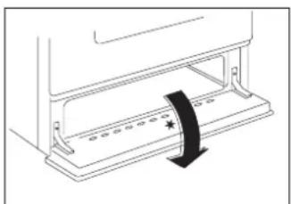
natural_image
Diagram of a device with a scroll wheel and directional arrow indicating rotation (no text or symbols)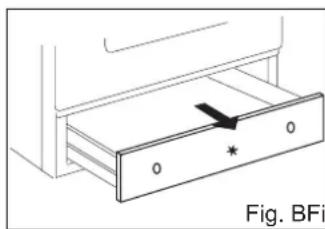
natural_image
Diagram of a drawer with an arrow indicating direction, labeled 'Fig. BFi' (no text or symbols on the diagram itself)Fig. BFig. A
CERAMIC WORK-TOP
The work-top is fitted with cooking areas of different diameter and power. The positions are clearly marked. The heating occurs only within the diameters marked on the work-top.
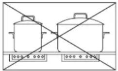
For efficient cooking and energy saving, it is essential to use only suitable saucepans.
Cookware with rough bottoms should not be used since these can scratch the ceramic surface. Before use, make sure that pan bottoms are clean and dry.
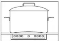
Pans should have the same diameter as the cooking zone they are used on.
When cold, pan bottoms should be slightly concave, as they expand when they are hot and lie flat on the surface of the hob. This transfers the heat best.
The best thickness for pan bottoms is 2-3 mm in case of enamelled steel and 4-6 mm for stainless steel with sandwich type bottoms.
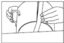
There is a simple way of checking whether the pan bottom is of the right shape (when cold).
Rest the middle of the bottom at an angle against the straight edge of a table and slip a few strips of typing paper between them.
As a guide five to ten pieces of paper is correct for enamelled steel pans and two to five strips for stainless steel (the higher number applies to the larger sizes of pan).
These rules are very important. If they are not followed there will be a great loss of heat and energy, and the heat not absorbed by the saucepan will spread to the hob, frame and surrounding cabinet.
Using the cooking hob.
The first few times the hob is used, it may give off acrid, burning smells. These will disappear completely with repeated use.
Each cooking area has a selector knob on the appliance control panel for setting different temperature levels.
For normal cooking, place the saucepan on the desired area of the hob and set the knob to the maximum heat.
A warning light on the control panel will inform you if the cooking area is on or off.
Some of the cooking work-tops have an indicator light between the two front cooking areas, which lights up when one or more of the cooking areas goes above the temperature of 60^ C.
The indicator light switches off only when the temperature of the cooking areas goes below about 60^ C.
After a few minutes, when the contents of the saucepan are boiling, turn the knob to a lower position, depending on the quantity, so that the saucepan does not splash over and there is no waste of heat.
Important
Be very careful about the safety of children when using the ceramic hob.
Attention
Although the hob surface is very tough, it is certainly not unbreakable and it can be damaged, especially if pointed or hard objects fall on it with a certain force.
Do not use the hob if the surface is broken or cracked; contact the assistance service immediately.
COOKING AREAS (according to the models)
The cooking area is controlled by a commutator.
Turn the knob until position 1 to turn the hotplate on (Fig.1).
COOKING AREAS WITH ENERGY REGULATOR
The cooking area is controlled by an energy regulator.
To activate the circuit, rotate the knob from 1 to 11 (Fig.2).
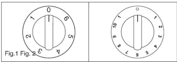
text_image
Fig.1 Fig. 2COOKING AREAS WITH DOUBLE CIRCUIT ENERGY REGULATOR
The cooking area is controlled by an energy regulator.
1) To activate the first circuit, rotate the knob from 1 to 11 (Fig.3).
2) To activate the second circuit, rotate the knob past the number 11, then repositioning on the required number.
To return to single-circuit operation, reset the knob to zero then to the number required.
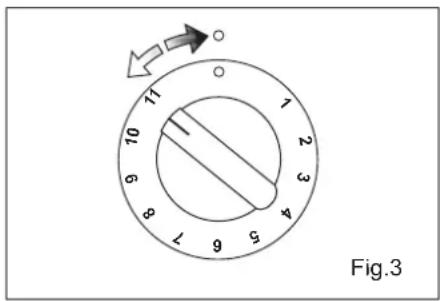
text_image
Fig.3GUIDELINE TABLE
The actual settings depend on the quantity and quality of the food and the type of saucepan.
| Pos. | Heat Intensity | Use | |
| 0 | 0 Off | ||
| 1 - 2 | 1 Very slow | For melting butter, chocolate, etc.For heating small amounts of liquid. | |
| 3 - 4 | 2 | Low | For heating larger amounts of liquid.For preparing slow-cooking creams and sauces. |
| 5 - 6 | 3 Medium-Low | For thawing frozen foods and cooking stews, cooking at boiling or lower temperatures. | |
| 7 - 8 | 4 Medium | For boiling foods, roasting delicate meats and fish. | |
| 9 - 10 | 5 High | For braising chops and steaks, for large meat soups. | |
| 11 | 6 Very high | For boiling large amounts of water and frying. | |
ENERGY SAVING TIPS
- The diameter of the saucepan must be the same or slightly larger than that of the electric hotplate. Never use a pan which is smaller than the electric hotplate.
- Use flat-bottomed pans only.
- Preferably cover pans with a lid to permit cooking at a lower heat.
• Always cook vegetables and potatoes, etc. in as little water to reduce cooking times.
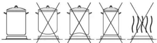
natural_image
Five line drawings of a pot with crossed panes and a wavy base, no text or symbols presentUSE OF THE ELECTRIC OVEN
The first time the oven is used, it may give off acrid smells, caused by the first heating of isolating panels glue surrounding the oven (it is necessary to heat up the oven at the maximum temperature for about 30-40 minutes with closed door).
It is something normal, and in case it will occur, wait for the smoke to stop before introducing the food into the oven.
The oven is fitted with: a rod shelf for cooking food contained in oven dishes or placed directly on the rod shelf itself, a drip-tray for cooking sweets, biscuits, pizzas, etc., or for collecting juices and fats from food cooked directly on the rod shelf.
Note: The following tables give the main points for cooking some of the most important dishes. The cooking times recommended in these tables are approximate. After a few tries, we are sure that you will be able to adjust the times to get the results you want.
Conventional cooking table.
| Dish Temp. °C. Minutes | ||
| Fish 180-240 acc. to size | ||
| Meat Roast ox 250 30 per kg. Roast veal 200-220 30 per kg. Chicken 200-240 50 about Duck and goose 220 Leg of mutton Roast pork Soufflets | acc. to weight 250 30 per kg. 250 60 per kg. 200 60 per kg. | |
| Sweets (pastries) Tea-cake Sponge finger Shortcrust pastry Puff pastry Fruit flan Meringues Quiches, etc. 4 quarters Buns | 160 160 200 250 200-220 100 220 120-140 160-180 | 50-60 30-50 15 15 30 60 30 60 45 |
Fan oven cooking table
| Dish | Temp. °C. | Minutes | Weight kg. |
| Firs courses | |||
| Lasagne | 200-220 | 20-25 | 0,5 |
| Oven pasta | 200-220 | 25-30 | 0,5 |
| Creole rice | 200-230 | 20-25 | 0,5 |
| Pizza | 210-230 | 30-45 | 0,5 |
| Meat | |||
| Roast veal | 160-180 | 65-90 | 1-1,2 |
| Roast pork | 160-170 | 70-100 | 1-1,2 |
| Roast ox | 170-190 | 40-60 | 1-1,2 |
| Roast beef joint | 170-180 | 65-90 | 1-1,2 |
| Roast fillet beef (rare) | 180-190 | 40-45 | 1-1,5 |
| Roast lamb | 140-160 | 100-130 | 1,5 |
| Roast chicken | 180 | 70-90 | 1-1,2 |
| Roast duck | 170-180 | 100-160 | 1,5-2 |
| Roast goose | 160-180 | 120-160 | 3-3,5 |
| Roast turkey | 160-170 | 160-240 | 5 approx. |
| Roast rabbit | 160-170 | 80-100 | 2 approx. |
| Roast hare | 170-180 | 30-50 | 2 approx. |
| Fish | 160-180 | acc. to weight | |
| Sweets (pastries) | |||
| Fruit flan | 180-200 | 40-50 | |
| Plain sandwich cake | 160-180 | 35-45 | |
| Sponge sandwich cake | 200-220 | 40-45 | |
| Sponge cake | 200-230 | 25-35 | |
| Currant cake | 230-250 | 30-40 | |
| Buns | 170-180 | 40-60 | |
| Strüdel | 160 | 25-35 | |
| Cream slices | 180-200 | 20-30 | |
| Apple fritters | 180-200 | 18-25 | |
| Sponge finger pudding | 170-180 | 30-40 | |
| Sponge finder biscuits | 150-180 | 50-60 | |
| Toasted sandwiches | 230-250 | 7 | |
| Bread | 200-220 | 40 |
1 - NATURAL CONVECTION OVENS
The oven is fitted with:
- a lower heating element;
- an upper heating element.
It is possible to select the desired temperature into the oven by turning clockwise the thermostat knob and depending on the models, one or more functions:

Oven off

Oven light
60 ÷ max Upper + lower heating element on

Upper heating element on

Lower heating element on

Grill element on (turnspit optional 📄)
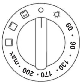
text_image
60 90 130 170 200 max2- MULTIFUNCTIONAL OVEN
Ovens with separate thermostat and commutator.
The oven is fitted with:
- a lower heating element;
- an upper heating element;
- a circular heating element surrounding the fan.
N.B.: Always set the temperature on the thermostat knob before selecting any of the functions.
Oven thermostat knob (fig. 3A)
To obtain an oven temperature between 50^ C and MAX ^ C, turn the knob clockwise.
Oven commutator knob (fig. 4)
Depending on the type of oven, it is possible to select one of the following functions turning the commutator knob clockwise.
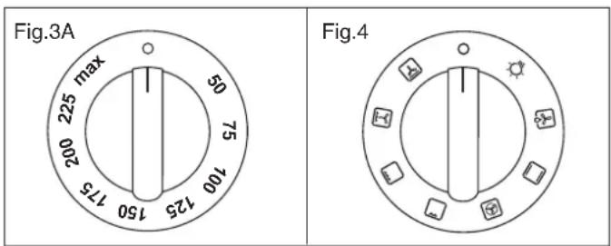
text_image
Fig.3A max 225 50 200 75 100 125 150 Fig.4Use of the oven
Note:
Always use the oven with the oven door closed.
When the functions are used, place the thermostat knob between 180 ÷ 200^ as maximum temperature.
ATTENTION:
The temperature shown on the control panel corresponds to the temperature in the oven centre only when the functions selected are
or.

When you turn the control knob to this position, the light will be on for all the following operations.

Defrosting with fan
The air at ambient temperature is distributed inside the oven for defrosting food very quickly and without proteins adulterations.

Natural convection
Both the lower and upper heating elements operate together.
This is the traditional cooking, very good for roasting joints, ideal for biscuits, baked apples and crisping food.
You obtain very good results when cooking on a shelf adjusting the temperature between 50 and MAX°C.

Fan oven
Both the fan and the circular heating element operate together.
The hot air adjustable between 50 and MAX°C is evenly distributed inside the oven. This is ideal for cooking several types of food (meat, fish) at the same time without affecting taste and smell.
It is indicated for delicate pastries.

Medium grill
It is indicated for grilling and gratinating small quantities of traditional food.
The thermostat knob must be placed on the maximum position.

Total grill
It is indicated for grilling and gratinating traditional food.
The thermostat knob must be placed between 180 ÷ 200^ position as maximum temperature.

Fan assisted total grill
The air which is heated by the grill heating element is circulated by the fan which distributes the heat on the food.
The fan assisted grill replaces perfectly the turnspit. You can obtain very good results also with large quantities of poultry, sausage, red meat. The thermostat knob must be placed between 180 ÷ 200^ position as maximum temperature.

Air forced lower heating element
The air which is heated by the lower heating element is circulated by the fan which distributes the heat on the food.
This function can be used to sterilize food. This function can be used between 50 and MAX°C
USE OF THE GRILL

Install the grid on the third shelf from the oven bottom, at about 12 cm from the surface.
The user can change the shelves, depending on his personal wishes and on the different food.
Geat the oven 5 minutes before introducing the food.
ATTENTION (small oven grill)
In some models, to use the grill you must first fit the control knob protection "S" supplied with the appliance and leave the door slightly open (see fig. 5).
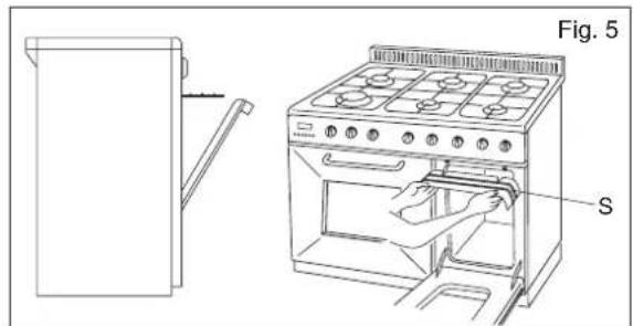
text_image
Fig. 5 STURNSPIT (optional)
In order to make the electric heating element work follow the instructions described in paragraph 1 page 5 position [→], this selection puts into function the turnspit as well.
USE OF THE TURNSPIT
For utilization of the turnspit follow the instructions described.
- Put the food in spit L (see fig. 5A), paying attention to block it within the two forks F and to balance it, in order to avoid any unnecessary effort in motor R (fig 5A).
- Put the spit on support G, after having put its opposite end into hole P of motor R.
- Place the drip-tray with a little water under the spit.
- (Only for models where present1 fit the control knob protection "S" supplied with the appliance and leave the door slightly open (see fig. 5).
- To remote the spit, operate in the opposite direction using knob A and protecting glove in isolating wool (see fig. 5A).
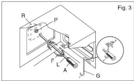
text_image
Fig. 3 R P F L A G R²INSTRUCTIONS FOR USE OF CONTROL DEVICES (ACCORDING TO THE MODELS)
"LED" PROGRAMMER (Fig. 7)
Features
24 hours clock with automatic programme and minutes counter.
Functions
Cooking time, cooking end time, manual position, clock, minutes counter, times to be set up to 23 hours 59 minutes.
Display
4-figures, 7-segments display for cooking times and time of day.
Cooking time and manual function = saucepan symbol
Automatic function = AUTO
Minutes counter = bell symbol
The symbols light up when the corresponding functions are selected.
Fig. 7
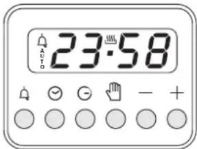
text_image
23:58| Minute timer | |
| Cooking time | |
| Cooking end | |
| Manual | |
| — | Subtract time |
| + | Add time |
Setting
To set, press and release the desired function, and within 5 seconds set the time with + and - buttons.
+ and - buttons.
The + and - buttons increase or decrease the time at a speed depending on how long the button is pressed.
Setting the time
Press the manual button at the same time, and + or - button to set the desired time. This deletes any previously set programme. The contacts are switched off.
Manual use
By pressing the manual button the relay contacts switch on, the AUTO symbol switches off and the saucepan symbol lights up.
Manual operation can only be enabled after the automatic programme is over or it has been cancelled.
Automatic use
Press the cooking time or end time button to switch automatically from the manual to the automatic function.
Semi-automatic use with cooking time setting
Press the cooking time button and set the desired time with + or -. The AUTO and cooking time symbols light up continuously. The relay switches on immediately. When the cooking end time corresponds to the time of day, the relay and cooking time symbol switch off, the sound signal rings and the AUTO symbol flashes.
Semi-automatic use with end time setting
Press the end time button. The time of day appears on the display. Set the cooking end time with + button. The AUTO and cooking time symbols light up continuously. The relay contacts switch on. When the cooking end time corresponds to the time of day, the relay and the cooking time symbol switch off. When the cooking time is up, the AUTO symbol flashes, the sound signal rings and both the relay and the cooking time button switch off.
Automatic use with cooking time and end time setting
Press the cooking time button and select the length of the cooking time with + or - button. The AUTO and cooking time symbols light up continuously. The relay switches on. By pressing the cooking end time button the next cooking end time appears on the display. Set the cooking end time with + button. The relay and the cooking time symbol switch off.
The symbol lights up again when the time of day corresponds to the cooking start time. When the cooking time is up, the AUTO symbol flashes, the sound signal rings, the cooking time symbol and the relay switch off.
Minutes counter
Press the minutes counter button and set the cooking time with + or - button.
The bell symbol lights up when the minutes counter is operating. When the set time is up, the sound signal rings and the bell symbol switches off.
Sound signal
The sound signal starts at the end of a programme or of the minutes counter function and it lasts for 15 minutes.
To stop it, push any one of the functions buttons.
Start programme and check
The programme starts 4 seconds after it has been set.
The programme can be checked at any time by pressing the corresponding button.
Setting error
A setting error is made if the time of day on the clock falls within the cooking start and end times.
To correct the setting error, change the cooking time or cooking end time.
The relays switch off when a setting error is made.
Cancelling a setting
To cancel a setting, press the cooking time button and then press the
- button until 00 00 appears on the display.
A set programme will automatically cancel on completion.
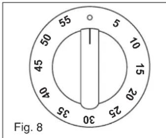
MINUTES COUNTERS (Fig.8)
Turn the knob clockwise to set the desired cooking time.
The minutes minder can be adjusted from 1 to 60 minutes.
A sound signal will inform you that the chosen time is up.
PROGRAMMER WITH COOKING END TIME (Fig.9)
For a manual operation of the programmer, turn the knob anticlockwise to 🔊.
Adjust the cooking time by turning the knob clockwise.
Select the cooking time with the relevant knob (max.120 min.).
The oven will switch off automatically when the cooking is up.
text_image
55 5 10 15 20 25 30 35 40 45 50 Fig. 8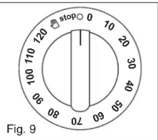
text_image
stop 0 120 100 110 120 10 20 30 40 50 60 70 Fig. 9ELECTRONIC TIMER FOR COOKER (Fig. 10)
Functions
On
The display flashes.
Time setting
Press the left button.
Set the time with buttons "+" and "-"
This function remains activated 7 seconds after the last +/- operation.
Timer setting
This function is permanently activated and it will be immediately set with +/- buttons.
During setting the units are 10 seconds.
During count down the timer takes priority on the display.
The units are seconds.
The maximum time is 99 minutes.
The relay contact (when available) is closed during the count down only.
Reset timer
Press “+” and “-” buttons together and release “+” button first.
Signal
The signal after time out will stay 7 minutes if it has not been reset with the "+" button (one touch only).
Signal frequency
When the display shows the time of day, the signal frequency can be selected by pressing the "-" button. Three different frequencies are selectable.
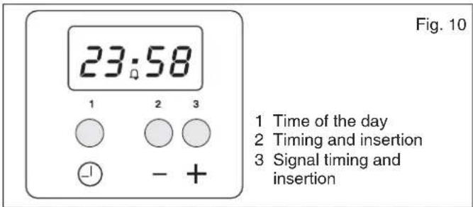
text_image
23:58 1 2 3 - + 1 Time of the day 2 Timing and insertion 3 Signal timing and insertion Fig. 10CARE AND MAINTENANCE
Before cleaning the appliance, disconnect the gas general tap and unplug the appliance or disconnect power at the main circuit breaker of the electrical system.
Do not clean the appliance surfaces when still hot. Do not use steam cleaners to clean the oven.
ENAMELLED SURFACES
Clean with a damp sponge using soap and water.
Grease can be easily removed using hot water or a specific cleansing agent for enamelled surfaces. Do not use abrasive cleansers.
Do not leave any acid or alkaline substances (lemon juice, vinegar, salt, etc.) on the enamel.
Clean the parts in stainless steel with specific cleansers for stainless steel surfaces.
These detergents must be applied using a soft cloth.
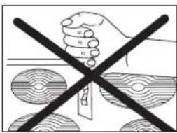
GLASS-CERAMIC SURFACE
To clean the work-top, you must follow the same precautions you use to clean the glasses of your house. Soft stains caused by aluminium pans bottoms can be removed by means of vinegar.
Make sure that sugar does not fall on the work-top during cooking, if it falls disconnect the relevant hotplate, and clean as soon as possible with hot water, before it gets cold.
In case there are stains of burnt sugar or similars after cooking, clean them using a spatule or a razor before the cooking zone becomes cold (see picture 10A).
text_image
Diagram showing a hand holding a cross over a patterned surface with a label 'H' and a small symbol inside the cross.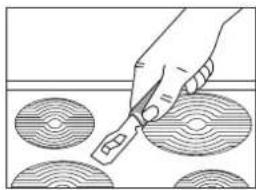
natural_image
Hand using a tool to cut circular patterns on a surface (no text or symbols visible)Fig. 10A
OVEN DOOR
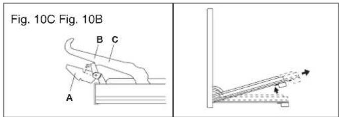
For some models, the oven door can be disassembled in the following way:
hinges A are provided, for this purpose, with two movable jumpers B; these, once hooked to the hinges slots C, when the door is completely opened, block them (fig 10C).
(Only where present, remove the inside door glass of the oven, see fig. 10B).
After that lift the door outward carrying out the two movements shown in the picture 10D. To do that, operate on the door sides next to the hinges. In order to re-assemble the door, introduce the hinges in their relevant slots.
Before closing the door, do not forget to remove the movable jumpers B. Attention, in proximity of the oven door hinges, there is hurt danger.
text_image
Fig. 10C Fig. 10B A B COVEN
Clean the enamelled parts with a damp sponge using soap and water. Grease can be easily removed using hot water or a specific cleansing agent for enamelled surfaces. Do not use abrasive cleansers.
INSTRUCTIONS DESTINED TO THE USER
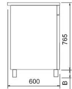
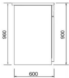
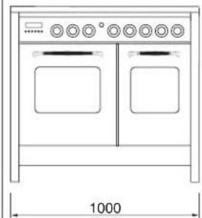
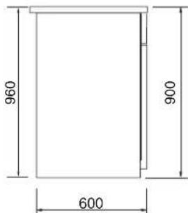
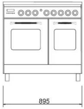
OVERALL DIMENSIONS (mod. 192)
natural_image
Line drawing of a two-door oven with control knobs and doorways, labeled with total height 895 (no text or symbols on the diagram itself)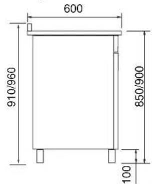
text_image
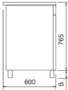
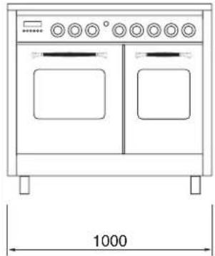
600 910/960 850/900 100OVERALL DIMENSIONS (mod. 108)
natural_image
Line drawing of a two-door electric oven with control knobs and a 1000 mm dimension label (no text or symbols on the device itself)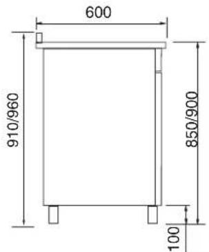
text_image
600 910/960 850/900 100WARNINGS
Do not use the oven door handle to move the appliance, such as to remove it from the packaging.
The appliance is in class 1 or class 2 subclass 1.
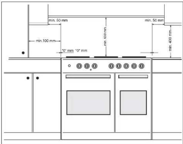
IMPORTANT: The coating of the furniture must be able to withstand high temperatures (min. 90°C).
If the appliance is to be installed near units, leave the minimum gaps specified in the table below.
The cooker must not be placed on a pedestal.
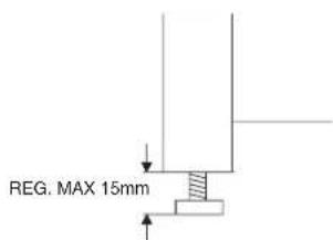
Some models are provided with 4 feet used for possible height alignment with the cabinets.
(see fig. 11, or 11A depending on the models).
Fig. 11
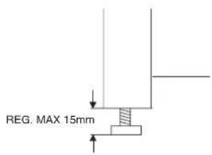
text_image
REG. MAX 15mmFig. 11 A
Lift the cooker and screw the four feet in the special threads located in the corners under the appliance.
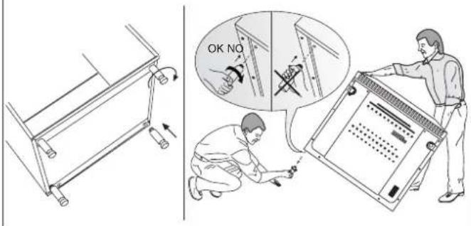
text_image
OK NOELECTRICAL CONNECTION
This appliance must be installed by a qualified person in accordance with local electrical safety rules and in compliance with the manufacturer instructions.
Ensure that the voltage is the same as that stated on the rating plate placed on the inside of the front appliance drawer.
WARNING!THIS APPLIANCE MUST BE EARTHED
If an fixed appliance is not equipped with supply cable and plug, the power supply must be fitted with a disconnect switch in which the distance between contacts permits total disconnection in accordance with overvoltage category III, as required by installation regulations.
Be sure that the earth wire green/yellow is not interrupted by the switch
| Appliance type Single-phase supply 230V~ | ||
| Type of cable Section | ||
| Alla gas + double oven | Rubber H05 RR-F or Rubber H05 RN-F | 3 x 2.5 mm ^2 |
| Ceramic work-top + double oven | * 3 x 6 mm ^2 | |
*
TAKING ACCOUNT OF CONTEMPORANEITY FACTOR OF 0,59
| Appliance type | Two-phase supply 400V~ | |
| Type of cable Section | ||
| Ceramic work-top + double oven | Rubber H05 RR-F orRubber H05 RR-F | 4 x 4 mm2 |
| Appliance type Three-phase supply 400V~ | ||
| Type of cable Section | ||
| Ceramic work-top + double oven | Rubber H05 RR-F or Rubber H05 RN-F | 5 x 2.5 mm ^2 |
Connecting the mains cable
Open the mains terminal block cover as shown, unscrew the cable clamp «A» and unscrew (not fully) the screws in the mains terminal block «L N E» which secure the three wires of the mains cable. Fit the cable and refit the cable clamp «A» (fig. N).
Allow sufficient cable length for the cooker to be pulled out for cleaning, but do not let it hang closer than 50mm (2») to the floor. The cable can be looped if necessary, but make sure that it is not kinked or trapped when the cooker is in position.
IMPORTANT
The wires in the mains lead are coloured in accordance with the following code:
GREEN AND YELLOW......EARTH
BLUE......NEUTRAL
BROWN ......LIVE
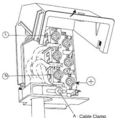
text_image
A Cable ClampFig. N
TYPE OF POWER SUPPLY
Different connections can be made simply by moving the jumpers on the terminal board
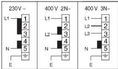
text_image
230V - L1 1 2 3 4 5 N E 400 V 2N- L1 1 2 3 4 5 N E 400 V 3N- L1 1 2 3 4 5 N EE = GREEN and Yellow / N = BLUE / L = BROWN
| plates | ∅ mm | Watt |
| F | 145 | 1200 |
| G - I | 180 | 1800 |
| H | 210 | 2200 |
| L | 265 | 1400/2200 |
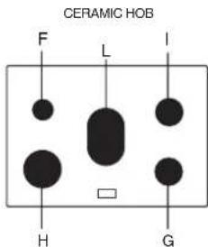
text_image
CERAMIC HOB F L I H GREPLACEMENT OF THE CABLE
In case the cable is damaged, replace it in accordance with the following instructions:
- disconnect the appliance from the electric network before any intervention.
- open the box of the supply board as described on the picture N;
- unscrew screw "A" fixing the cable ;
- replace the cable with one of the same length and in accordance with the features described on the table; switch the appliance off, and close the gas tap
- the 'green-yellow" earth wire must be connected to the terminal "⊥" and it must be about 10 mm longer than the live wires;
- the "blue" neutral wire must be connected to the terminal marked with letter "N";
- the live wire must be connected to the terminal marked with letter "L".
APPLIANCE MAINTENANCE
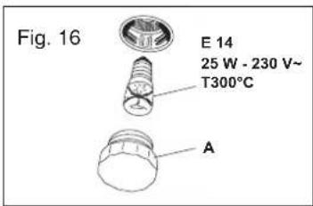
WARNINGS
Isolate the cooker from the electricity supply before attempting to replace the oven lamp.
The oven lamp used is of a special type withstanding high temperatures. To replace it, act as follows: disassemble the protecting glass (A) fig. 16 and replace the burnt lamp with one of the same type. Reassemble the protecting glass.