
DA8000 - Surveillance Camera Monacor - Free user manual and instructions
Find the device manual for free DA8000 Monacor in PDF.
| Product Type | Microprocessor alarm control panel with 8 zones |
| Brand | Monacor |
| Model | DA8000 |
| Number of Zones | 8 programmable zones |
| Tamper Loop | 1 for sensors, 1 for alarm unit |
| Max. Allowed Loop Resistance | 2 kΩ |
| Trigger Time | 300 ms |
| Entry Delay | Adjustable 0-198 s, preset 40 s |
| Exit Delay | Adjustable 0-99 s, preset 30 s |
| Alarm Duration | Adjustable 1 s-99 min, preset 20 min |
| Event Memory | 64 events with date/time (preset) or 256 without |
| Power Supply | 230 V~ / 50 Hz / 50 VA + 12 V battery min. 2 Ah |
| Control Panel Consumption | 12 V, max. 50 mA |
| Keypad Consumption | 12 V, max. 40 mA per keypad |
| Fuses | Mains T125 mA, F1 1 A fast, F2 250 mA fast |
| Operating Temperature | 0-50 °C |
| Control Panel Dimensions | 250 x 195 x 75 mm |
| Control Panel Weight | 1.3 kg |
| Keypad Dimensions | 90 x 115 x 25 mm |
| Keypad Weight | 150 g |
| Max. Keypads | 4 (one supplied) |
| PGM1 Output | Programmable (12 V, max. 50 mA) |
| Maintenance and Cleaning | Dry soft cloth, no chemicals |
| Safety | Protection class II, indoor use, do not expose to water |
Frequently Asked Questions - DA8000 Monacor
User questions about DA8000 Monacor
0 question about this device. Answer the ones you know or ask your own.
Ask a new question about this device
Download the instructions for your Surveillance Camera in PDF format for free! Find your manual DA8000 - Monacor and take your electronic device back in hand. On this page are published all the documents necessary for the use of your device. DA8000 by Monacor.
USER MANUAL DA8000 Monacor
flowchart
```mermaid
graph TD
    A["Start"] --> B{Test Mode}
    B -->|Yes| C["Test Mode 1"]
    B -->|No| D["Test Mode 2"]
    C --> E{Test Mode 3}
    D --> F{Test Mode 4}
    E --> G{Test Mode 5}
    F --> H{Test Mode 6}
    G --> I{Test Mode 7}
    H --> J{Test Mode 8}
    I --> K{Test Mode 9}
    J --> L{Test Mode 10}
    K --> M{Test Mode 11}
    L --> N{Test Mode 12}
    M --> O{Test Mode 13}
    N --> P{Test Mode 14}
    O --> Q{Test Mode 15}
    P --> R{Test Mode 16}
    Q --> S{Test Mode 17}
    R --> T{Test Mode 18}
    S --> U{Test Mode 19}
    T --> V{Test Mode 20}
    U --> W{Test Mode 21}
    V --> X{Test Mode 22}
    W --> Y{Test Mode 23}
    X --> Z{Test Mode 24}
    Y --> AA{Test Mode 25}
    Z --> AB{Test Mode 26}
    AA --> AC{Test Mode 27}
    AB --> AD{Test Mode 28}
    AC --> AE{Test Mode 29}
    AD --> AF{Test Mode 30}
    AE --> AG{Test Mode 31}
    AF --> AH{Test Mode 32}
    AG --> AI["End"]
    AH --> AJ["End"]

    subgraph Test Mode
        C
        D
        E
        F
        G
        H
        I
        J
        K
        L
        M
        N
        O
        P
        Q
        R
        S
        T
        U
        V
        W
        X
        Y
        Z
        AA
        AB
        AC
        AD
        AE
        AF
        AG
        AH
    end

    subgraph Test Mode 1
        C
        D
        E
        F
        G
        H
        I
        J
        K
        L
        M
        N
        O
        P
        Q
        R
        S
        T
        U
        V
        W
        X
        Y
        Z
    end

    subgraph Test Mode 2
        C
        D
        E
        F
        G
        H
        I
        J
        K
        L
        M
        N
        O
        P
        Q
        R
        S
        T
        U
        V
        W
        X
        Y
        Z
    end

    subgraph Test Mode 3
        C
        D
        E
        F
        G
        H
        I
        J
        K
        L
        M
        N
        O
        P
        Q
        R
        S
        T
        U
        V
        W
        X
        Y
        Z
    end

    subgraph Test Mode 4
        C
        D
        E
        F
        G
        H
        I
        J
        K
        L
        M
        N
        O
        P
        Q
        R
        S
        T
        U
        V
        W
        X
        Y
        Z
    end

    subgraph Test Mode 5
        C
        D
        E
        F
        G
        H
        I
        J
        K
        L
        M
        N
        O
        P
        Q
        R
        S
        T
        U
        V
        W
        X
        Y
        Z
    end

    subgraph Test Mode 6:
        C
        D
        E
        F
        G
        H
        I
        J
        K
        L
        M
        N
        O
        P
        Q
        R)
    end

    subgraph Test Mode 7:
        C1["Set to test mode"]
    end

    subgraph Test Mode 8:
            C2["Set to test mode"]
            C3["Set to test mode"]
            C4["Set to test mode"]
            C5["Set to test mode"]
            C6["Set to test mode"]
            C7["Set to test mode"]
            C8["Set to test mode"]
            C9["Set to test mode"]
            C10["Set to test mode"]
            C11["Set to test mode"]
            C12["Set to test mode"]
            C13["Set to test mode"]
            C14["Set to test mode"]
            C15["Set to test mode"]
            C16["Set to test mode"]
            C17["Set to test mode"]
            C18["Set to test mode"]
            C19["Set to test mode"]
            C20["Set to test mode"]
            C21["Set to test mode"]
            C22["Set to test mode"]
            C23["Set to test mode"]
            C24["Set to test mode"]
            C25["Set to test mode"]
            C26["Set to test mode"]
            C27["Set to test mode"]
            C28["Set to test mode"]
            C29["Set to test mode"]
            C30["Set to test mode"]
            C31["Set to test mode"]
            C32["Set to test mode"]
            C33["Set to test mode"]
            C34["Set to test mode"]
            C35["Set to test mode"]
            C36["Set to test mode"]
            C37["Set to test mode"]
            C38["Set to test mode"]
            C39["Set to test mode"]
            C40["Set to test mode"]
            C41["Set to test mode"]
            C42["Set to test mode"]
            C43["Set to test mode"]
            C44["Set to test mode"]
            C45["Set to test mode"]
            C46["Set to test mode"]
            C47["Set to test mode"]
            C48["Set to test mode"]
            C49["Set to test mode"]
            C50["Set to test mode"]
            C51["Set to test mode"]
            C52["Set to test mode"]
            C53["Set to test mode"]
            C54["Set to test mode"]
            C55["Set to test mode"]
            C56["Set to test mode"]
            C57["Set to test mode"]
            C58["Set to test mode"]
            C59["Set to test mode"]
            C60["Set to test mode"]
            C61["Set to test mode"]
            C62["Set to test mode"]
            C63["Set to test mode"]
            C64["Set to test mode"]
            C65["Set to test mode"]
            C66["Set to test mode"]
            C67["Set to test mode"]
            C68["Set to test mode"]
            C69["Set to test mode"]
            C70["Set to test mode"]
            C71["Set to test mode"]
            C72["Set to test mode"]
            C73["Set to test mode"]
            C74["Set to test mode"]
            C75["Set to test mode"]
            C76["Set to test mode"]
            C77["Set to test mode"]
            C78["Set to test mode"]
            C79["Set to test mode"]
            C80["Set to test mode"]
            C81["Set to test mode"]
            C82["Set to test mode"]
            C83["Set to test mode"]
            C84["Set to test mode"]
            C85["Set to test mode"]
            C86["Set to test mode"]
            C87["Set to test mode"]
            C88["Set to test mode"]
            C89["Set to test mode"]
            C90["Set to test mode"]
            C91["Set to test mode"]
            C92["Set to test mode"]
            C93["Set to test mode"]
            C94["Set to test mode"]
            C95["Set to test mode"]
            C96["Set to test mode"]
            C97["Set to test mode"]
            C98["Set to test mode"]
            C99["Set to test mode"]

    end

    subgraph Legend Structure & Features of the Zones & Features of the Zones & Features of the Zones & Features of the Zones & Features of the Zones & Features of the Zones & Features of the Zones & Features of the Zones & Features of the Zones & Features of the Zones & Features of the Zones & Features of the Zones & Features of the Zones & Features of the Zones & Features of the Zones & Features of the Zones & Features of the Zones & Features of the Zones & Features of the Zones & Features of the Zones & Features of the zones & Features of the Zones & Features of the Zones & Features of the Zones & Features of the Zones & Features of the Zones & Features of the Zones & Features of the Zones & Features of the Zones & Features of the Zones & Features of the Zones & Features of the Zones & Features of the Zones & Features of the Zones & Features of the Zones & Features of the Zones & Features of the Zones & Features of the Zones & Features of the Zones & Features of the Zones & Features of the Zenerals & Features of the Zones & Features of the Zones & Features of the Zones & Features of the Zones & Features of the Zones & Features of the Zones & Features of the Zones & Features of the Zones & Features of the Zones & Features of the Zones & Features of the Zones & Features of the Zones & Features of the Zones & Features of the Zones & Features of the Zones & Features of the Zones & Features of the Zones & Features of the Zones & Features of the Zones & Features of the Regions & Features of the Zones & Features of the Zones & Features of the Zones & Features of the Zones & Features of the Zones & Features of the Zones & Features of the Zones & Features of the Zones & Features of the Zones & Features of the Zones & Features of the Zones & Features of the Zones & Features of the Zones & Features of the Zones & Features of the Zones & Features of the Zones & Features of the Zones & Features of the Zones & Features of the Zones & Features of the Zone & Features of the Zones & Features of the Zones & Features of the Zones & Features of the Zones & Features of the Zones & Features of the Zones & Features of the Zones & Features of the Zones & Features of the Zones & Features of the Zones & Features of the Zones & Features of the Zones & Features of the Zones & Features of the Zones & Features of the Zones & Features of the Zones & Features of the Zones & Features of the Zones & Features of the Zones & Features of the Groups & Features of the Zones & Features of the Zones & Features of the Zones & Features of the Zones & Features of the Zones & Features of the Zones & Features of the Zones & Features of the Zones & Features of the Zones & Features of the Zones & Features of the Zones & Features of the Zones & Features of the Zones & Features of the Zones & Features of the Zones & Features of the Zones & Features of the Zones & Features of the Zones & Features of the Zones & Features of the Gates & Features of the Zones & Features of the Gates & Features of the Gates & Features of the Gates & Features of the Gates & Features of the Gates & Features of the Gates & Features of the Gates & Features of the Gates & Features of the Gates & Features of the Gates & Features of the Gates & Features of the Gates & Features of the Gates & Features of the Gates & Features of the Gates & Features of the Gates & Features / The Gates |
    end

    subgraph Legend Structure &
      Legend Structure1: Zenerale School System (set or unseated)
      Legend Structure2: Test Mode |
      Legend Structure3: Zenerale School System (set or unseated)
      Legend Structure4: Test Mode |
      Legend Structure5: Zenerale School System (set or unseated)
      Legend Structure6: Test Mode |
      Legend Structure7: Zenerale School System (set or unseated)
      Legend Structure8: Test Mode |
      Legend Structure9: Zenerale School System (set or unseated)
      Legend Structure10: Test Mode |
      Legend Structure11: Zenerale School System (set or unseated)
      Legend Structure12: Test Mode |
      Legend Structure13: Zenerale School System (set or unseated)
      Legend Structure14: Test Mode |
      Legend Structure15: Zenerale School System (set or unseated)
      Legend Structure16: Test Mode |
      Legend Structure17: Zenerale School System (set or unseated)
      Legend Structure18: Test Mode |
      Legend Structure19: Zenerale School System (set or unseated)
      Legend Structure20: Test Mode |
      Legend Structure21: Zenerale School System (set or unseated)
      Legend Structure22: Test Mode |
      Legend Structure23: Zenerale School System (set or unseated)
      Legend Structure24: Test Mode |
      Legend Structure25: Zenerale School System (set or unseated)
      Legend Structure26: Test Mode |
      Legend Structure27: Zenerale School System (set or unseated)
      Legend Structure28: Test Mode |
      Legend Structure29: Zenerale School System (set or unseated)
      Legend Structure30: Test Mode |
      Legend Structure31: Zenerale School System (set or unseated)
      Legend Structure32: Test Mode |
      Legend Structure33: Zenerale School System (set or unseated)
      Legend Structure34: Test Mode |
      Legend Structure35: Zenerale School System (set or unseated)
      Legend Structure36: Test Mode |
      Legend Structure37: Zenerale School System (set or unseated)
      Legend Structure38: Test Mode |
      Legend Structure39: Zenerale School System (set or unseated)
      Legend Structure40: Test Mode |
      Legend Structure41: Zenerale School System (set or unseated)
      Legend Structure42: Test Mode |
      Legend Structure43: Zenerale School System (set or unseated)
      Legend Structure44: Test Mode |
      Legend Structure45: Zenerale School System (set or unseated)
      Legend Structure46: Test Mode |
      Legend Structure47: Zenerale School System (set or unseated)
      Legend Structure48: Test Mode |
      Legend Structure49: Zenerale School System (set or unseated)
      Legend Structure50: Test Mode |
      Legend Structure51: Zenerale School System (set or unseated)
      Legend Structure52: Test Mode |
      Legend Structure53: Zenerale School System (set or unseated)
      Legend Structure54: Test Mode |
      Legend Structure55: Zenerale School System (set or unseated)
      Legend Structure56: Test Mode |
      Legend Structure57: Zenerale School System (set or unseated)
      Legend Structure58: Test Mode |
      Legend Structure59: Zenerale School System (set or unseated)
      Legend Structure60: Test Mode |
      Legend Structure61: Zenerale School System (set or unseated)
      Legend Structure62: Test Mode |
      Legend Structure63: Zenerale School System (set or unseated)
      Legend Structure64: Test Mode |
      Legend Structure65: Zenerale School System (set or unseated)
      Legend Structure66: Test Mode |
      Legend Structure67: Zenerale School System (set or unseated)
      Legend Structure68: Test Mode |
      Legend Structure69: Zenerale School System (set or unseated)
      Legend Structure70: Test Mode |
      Legend Structure71: Zenerale School System (set or unseated)
      Legend Structure72: Test Mode |
      Legend Structure73: Zenerale School System (set or unseated)
      Legend Structure74: Test Mode |
      Legend Structure75: Zenerale School System (set or unseated)
      Legend Structure76: Test Mode |
      Legend Structure77: Zenerale School System (set or unseated)
      Legend Structure78: Test Mode |
      Legend Structure79: Zenerale School System (set or unseated)
      Legend Structure80: Test Mode |
      Legend Structure81: Zenerale School System (set or unseated)
      Legend Structure82: Test Mode |
      Legend Structure83: Zenerale School System (set or unseated)
      Legend Structure84: Test Mode |
      Legend Structure85: Zenerale School System (set or unseated)
      Legend Structure86: Test Mode |
      Legend Structure87: Zenerale School System (set or unseated)
      Legend Structure88: Test Mode |
      Legend Structure89: Zenerale School System (set or unseated)
      Legend Structure90: Test Mode |
      Legend Structure91: Zenerale School System (set or unseated)
      Legend Structure92: Test Mode |
      Legend Structure93: Zenerale School System (set or unseated)
      Legend Structure94: Test Mode |
      Legend Structure95: Zenerale School System (set or unseated)
      Legend Structure96: Test Mode |
      Legend Structure97: Zenerale School System (set or unseated)
      Legend Structure98: Test Mode |
      Legend Structure99: Zenerale School System (set or unseated)
      Legend Structure100: Test Mode |
- Erwerer, John Zorke, 2016; 32:14:45. Wollinger's 19 g. on 03: Achtual
- Midsection: 10 Second section
2) The Canadian 100% CASH MARGIN
by the Akamakas F#2, which is also
Folgering and more. A second half-sphere space is
GB Further Options
Resetting the programming to the factory default
1) Disconnect the mains voltage and the rechargeable battery or simply
непрован THE COHNSPONDING BANK
2) Well for at least 10 seconds.
3) Apply the mains voltage again insert the mains luge again.
4) Apply the Maths Volume game [Pictet & C. Math is here again].
4) As such as V., Please wait is displayed, press the following 1, 4, 7, No.
NO.
6) Apply the voltage of the rechargeable battery again.
Changing the mode for the log
It is possible to store respectively:
-
the last 64 events with data and four factors default or
-
the last 20% counts without indication of date and now this rolling is
- the last 200 events method research of data
K30: OVER
Annomori
By charging the mode calling all points in both sets and finished. This pro-
ccture is indicated in the log as entry "L-Rat" (Log Base).
1) Disconnect the main voltage and the rechargeable battery or simply
remove the corresponding uses.
2) 19:00 at level 10 seconds.
- Keep the main vatten coil, closest main 4 no again
5) Apply the means to manage again, when means can again.
4) As soon as "V... Please Wall is displayed.
for the option B of 256 events:
press the buttons 0, 0, 7, No-
for the option A of 64 events:
press the buttons 9, 1, 7. No
6) Apply the voltage of the rechargeable battery again.
- The salary must be increased only before the salary payables in line, education and sale.
the step inside the first step, we have been a copy of the paper. The paper is then closed, and now has been open.
In the socially and visually
flowchart
graph TD
    A["Start"] --> B{Decision 1}
    B -->|Yes| C["Initiative: Approve the central"]
    B -->|No| D["End"]
    C --> E{Decision 2}
    E -->|Yes| F["Approve the central"]
    E -->|No| G["End"]
    F --> H{Decision 3}
    H -->|Yes| I["Approve the central"]
    H -->|No| J["End"]
    I --> K{Decision 4}
    K -->|Yes| L["Approve the central"]
    K -->|No| M["End"]
    L --> N{Decision 5}
    N -->|Yes| O["Approve the central"]
    N -->|No| P["End"]
    O --> Q{Decision 6}
    Q -->|Yes| R["Approve the central"]
    Q -->|No| S["End"]
    R --> T{Decision 7}
    T -->|Yes| U["Approve the central"]
    T -->|No| V["End"]
    U --> W{Decision 8}
    W -->|Yes| X["Approve the central"]
    W -->|No| Y["End"]
    X --> Z{Decision 9}
    Z -->|Yes| AA["Approve the central"]
    Z -->|No| AB["End"]
    AA --> AC{Decision 10}
    AC -->|Yes| AD["Approve the central"]
    AC -->|No| AE["End"]
    AD --> AF{Decision 11}
    AF -->|Yes| AG["Approve the central"]
    AF -->|No| AH["End"]
    AG --> AI{Decision 12}
    AI -->|Yes| AJ["Approve the central"]
    AI -->|No| AK["End"]
    AJ --> AL{Decision 13}
    AL -->|Yes| AM["Approve the central"]
    AL -->|No| AN["End"]
    AM --> AO{Decision 14}
    AO -->|Yes| AP["Approve the central"]
    AO -->|No| AQ["End"]
    AP --> AR{Decision 15}
    AR -->|Yes| AS["Approve the central"]
    AR -->|No| AT["End"]
    AS --> AU{Decision 16}
    AU -->|Yes| AV["Approve the central"]
    AU -->|No| AW["End"]
    AV --> AX{Decision 17}
    AX -->|Yes| AY["Approve the central"]
    AX -->|No| AZ["End"]
    AY --> BA{Decision 18}
    BA -->|Yes| BB["Approve the central"]
    BA -->|No| BC["End"]
F: CH ● Autres options
To date it is justified correspondence
4) Non-accrual Display Index "X - Phase Well"
flowchart
```mermaid
graph TD
    A["Anhang 1: Signal T1 For the beginning of next step"] --> B["Step 1: Signal T2 to Signal T3"]
    B --> C["Step 2: Signal T4 to Signal T5"]
    C --> D["Step 3: Signal T6 to Signal T7"]
    D --> E["Step 4: Signal T8 to Signal T9"]
    E --> F["Step 5: Signal T10 to Signal T11"]
    F --> G["Step 6: Signal T12 to Signal T13"]
    G --> H["Step 7: Signal T14 to Signal T15"]
    H --> I["Step 8: Signal T16 to Signal T17"]
    I --> J["Step 9: Signal T18 to Signal T19"]
    J --> K["Step 10: Signal T20 to Signal T21"]
    K --> L["Step 11: Signal T22 to Signal T23"]
    L --> M["Step 12: Signal T24 to Signal T25"]
    M --> N["Step 13: Signal T26 to Signal T27"]
    N --> O["Step 14: Signal T28 to Signal T29"]
    O --> P["Step 15: Signal T30 to Signal T31"]
    P --> Q["Step 16: Signal T32 to Signal T33"]
    Q --> R["Step 17: Signal T34 to Signal T35"]
    R --> S["Step 18: Signal T36 to Signal T37"]
    S --> T["Step 19: Signal T38 to Signal T39"]
    T --> U["Step 20: Signal T40 to Signal T41"]
    U --> V["Step 21: Signal T42 to Signal T43"]
    V --> W["Step 22: Signal T44 to Signal T45"]
    W --> X["Step 23: Signal T46 to Signal T47"]
    X --> Y["Step 24: Signal T48 to Signal T49"]
    Y --> Z["Step 25: Signal T50 to Signal T51"]
    Z --> AA["Step 26: Signal T52 to Signal T53"]
    AA --> AB["Step 27: Signal T54 to Signal T55"]
    AB --> AC["Step 28: Signal T56 to Signal T57"]
    AC --> AD["Step 29: Signal T58 to Signal T59"]
    AD --> AE["Step 30: Signal T60 to Signal T61"]
    AE --> AF["Step 31: Signal T62 to Signal T63"]
    AF --> AG["Step 32: Signal T64 to Signal T65"]
    AG --> AH["Step 33: Signal T66 to Signal T67"]
    AH --> AI["Step 34: Signal T68 to Signal T69"]
    AI --> AJ["Step 35: Signal T70 to Signal T71"]
    AJ --> AK["Step 36: Signal T72 to Signal T73"]
    AK --> AL["Step 37: Signal T74 to Signal T75"]
    AL --> AM["Step 38: Signal T76 to Signal T77"]
    AM --> AN["Step 39: Signal T78 to Signal T79"]
    AN --> AO["Step 40: Signal T80 to Signal T81"]
    AO --> AP["Step 41: Signal T82 to Signal T83"]
    AP --> AQ["Step 42: Signal T84 to Signal T85"]
    AQ --> AR["Step 43: Signal T86 to Signal T87"]
    AR --> AS["Step 44: Signal T88 to Signal T89"]
    AS --> AT["Step 45: Signal T90 to Signal T91"]
    AT --> AU["Step 46: Signal T92 to Signal T93"]
    AU --> AV["Step 47: Signal T94 to Signal T95"]
    AV --> AW["Step 48: Signal T96 to Signal T97"]
    AW --> AX["Step 49: Signal T98 to Signal T99"]
    AX --> AY["Step 50: Signal T100 to Signal T101"]
    AY --> AZ["End - Ausinhervolgsung Signatistierung beim Schottschatten schritte Schaffschaltung sowie delay and anti-delay signaling when activating quick activation"]

    subgraph Systematic Components
        direction LR
        A
        B
        C
        D
        E
        F
        G
        H
        I
        J
        K
        L
        M
        N
        O
        P
        Q
        R
        S
        T
        U
        V
        W
        X
        Y
        Z
        AA
        AB
        AC
        AD
        AE
        AF
        AG
        AH
        AI
        AJ
        AK
        AL
        AM
        AN
        AO
        AP
        AQ
        AR
        AS
        AT
        AU
        AV
        AW
        AX
        AZ
        BA
        AR
        AS
        AT
        AU
        AV
        AW
        AX
        AZ
        BA
        AR
        AT
        AU
        AV
        AW
        AX
        AZ
        BA
        AR
        AT
        AU
        AV
        AW
        AX
        AZ
        BA
        AR
        AT
        AU
        AV
        AW
        AX
        AZ
        BA
        AR
        AT
        AU
        AV
        AW
        AX
        AZ
        BA
        AR
        AT)
            A,B,C,D,E,F,G,H,I,J,K,L,M,N,O,P,Q,R,S,T,U,V,X,Y,Z,W,A,X,Y,U,V,X,X,Y,N,O,P,Q,R,S,T,U,V,X,Y,N,O,P,Q,R,S,T,U,V,X,X,Y,N,O,P,Q,R,S,T,U,V,X,X,Y,N,O,P,Q,R,S,T,U,V,X,X,Y,N,O,P,Q,R,S,T,U,V,X,X,Y,N,O,P,Q,R,S,T,U,V,X,X,Y,N,O,P,Q,R,S,T,U,V,X,X,Y,N,O,P,Q,R,S,T,U,V,X,X,Y,N,O,P,Q,R,S,T,U,V,X,X,Y,N,O,P,Q,R,S,T,U,V,X,X,Y,N,o,p,q,r,s,t,v,t,v,t,v,t,v,t,v,t,v,t,v,t,v,t,v,t,v,t,v,t,v,t,v,t,v,t,v,t,v,t,v,t,v,t,v,t,v,t,v,t,v,t,v,t,v,t,v,t,v,t,v,t,v,t,v,t,v,t,v,t,v,t,v,t,v,t,v,t,v,t,v,t,v,t,v,t,v,t,v,t,v,t,v,t,v,t,v,t,v,t,v,t,v,t,v,t,v,t,u,v,u,v,u,v,u,v,u,v,u,v,u,v,u,v,u,v,u,v,u,v,u,v,u,v,u,v,u,v,u,v,u,v,u,v,u,v,u,v,u,v,u,v,u,v,u,v,u,v,u,v,u,v,u,v,u,v,u,v,u,v,u,v,u,v,u,v,u,v,u,v,u,v,u,v,u,v,u,v,u,v,u,v,u,v,u,v,u,v,u,v,u,v,u,v,u,v,u,v,u,\n\n\n\n\n\n\n\n\n\n\n\n\n\n\n\n\n\n\n\n\n\n\n\n\n\n\n\n\n\n\n\n\n\n\n\n\n\n\n\n\n\n\n\n\n\n\n\n\n\n\n\n\n\n\n\n\n\n\n\n\n\n\n\n\n\n\n\n\n\n\n\n\n\n\n\n\n\n\n\n\n\n\n\n\n\n\n\n\n\n\n\n\n\n\n\n\n\n\n\n\n<ecel><ecel><ecel><ecel><ecel><ecel><ecel><ecel><ecel><ecel><ecel><ecel><ecel><ecel><ecel><ecel><ecel><ecel><ecel><ecel><ecel><ecel><ecel><ecel><ecel><ecel><ecel><ecel><ecel><ecel><ecel><ecel><ecel><ecel><ecel><ecel><ecel><ecel><ecel><ecel><ecel><ecel><ecel><ecel><ecel><ecel><ecel><ecel><ecel><ecel><ecel><ecel><ecel><ecel><ecel><ecel><ecel><ecel><ecel><ecel><ecel><ecel><ecel><ecel><ecel><ecel><ecel><ecel><ecel><ecel><ecel><nl>
security
by MONACOR ^a
www.mongcer.com
DA-8000
Best.-Nr. 04.3060
F:CH
1
text_image
Security by MONACOR®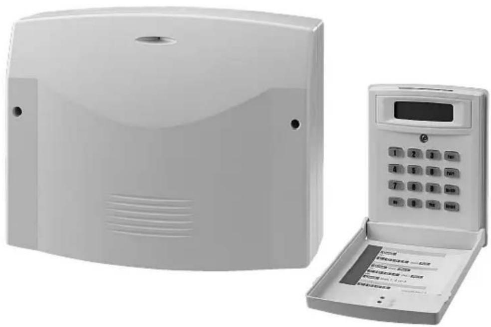
natural_image
Exterior view of a white electronic device with a digital display and control panel (no visible text or symbols)DA-8000
Best.-Nr. 04.3060
S Innan installation ...
GB Prior to the installation ...
Please read these instructions carefully prior to the installation. Thus, you will be able to know all functional and connecting facilities, errors will be prevented, and yourself and the unit will be protected against any damage caused by improper way of proceeding. Please keep the instructions for later use.
The English text starts on page 22.
ET (Exit Terminator)
Pt E/E (Part Entry /Exit)
| Do You Want to.. Set Engineer ? |
| Do You Want to..Test ? |
| Do You Want to..Delete Zone ? |
| Do You Want to..Select Options ? |
| Do You Want to..View Log ? |
| Program .......Exit/Entry ? |
T/EE (Time or Entry/Exit)
ET (Exit Terminator)
Program ...... Exit/Entry ?
Do You Want to.. Set Engineer?
Do You Want to.. Program Chime ?
Do You Want to.. Set Engineer?
1.2 Rear side of housing 23
2 Safety Notes 23
3 Applications and Accessories ..... 23
4 Installation 24
4.1 Way of proceeding 24
4.2 Connection cables 24
4.3 Mounting the alarm control system and the speaker 24
4.4 Mounting and connecting the keypad controllers ..... 24
4.5 Making the connections ..... 25
4.5.1 Speaker 25
4.5.2 Alarm unit or individual strobelight and siren 25
4.5.3 Opening sensors for windows and doors .. 25
4.5.4 PIR motion detectors ..... 26
4.5.5 Fire and smoke detectors ..... 26
4.5.6 Glass break detectors ..... 26
4.5.7 Raid detectors (panic button) ..... 26
4.5.8 Key switch or code lock 27
4.5.9 Telephone dialling unit 27
4.5.10 Guiding the anti-tamper loops of the alarm zones to the connection TMP ..... 27
4.5.11 12 V Rechargeable battery ..... 27
4.5.12 Mains voltage 27
5 Programming 28
5.1 Programming the features of the zones ..... 28
5.2 Entry delay and exit delay Signalizing when activating activation ..... 30
5.3 Settings for the alarm triggering and the panic button 31
5.4 Control output PGM1 32
5.5 Alarm reset authorization and alarm triggering via the keypad controller ... 33
5.6 Terminating the programming mode ..... 34
5.7 Changing the access code for programming . 34
5.8 Changing the mode for the log ..... 35
5.9 Resetting to the factory default ..... 36
5.10 Further information on the operation ..... 36
6 Test Mode 36
7 Trouble Shooting 36
8 Specifications 38
Default setting 39
Programmed parameters 81
Please unfold page 3. Then you can always see the operating elements described.
1 Component Parts
1.1 Inside view (fig. 1)
1 Terminal strip TB5 for the power supply
2 x "AC": alternating voltage from the mains transformer
"Bat +": to the positive pole of a 12 V rechargeable battery
"Bat –": to the negative pole of the rechargeable battery
2 Terminal strip TB1 for connection of up to four keypad controllers; to be connected to the contacts of the same name of the terminal TB1 at the keypad controller, also see chapter 4.4
3 Fuses:
F1 = quick-acting 1 A for the outputs "Strobe" and "Bell" of the terminal strip TB3 (5) and for the output "AUX 12V" of the terminal TB4 (6)
F2 = quick-acting 0.25 A for the keypad controllers Only replace a blown fuse by one of the same type!
4 Holding clamps for the PCB (10)
5 Terminal strip TB3 for connecting an alarm unit
“Strobe”: to the strobelight; max. current rating 250 mA*
“Bell”: to the siren; max. current rating 500 mA*
"Bell SAB": anti-tamper loop for the alarm unit or for an individual strobelight and siren
Note: For the power supply of an alarm unit a 12V rechargeable battery must be inserted which supports the internal power supply unit in case of alarm.
6 Terminal strip TB4
"PGM1": programmable switching output (chapter 5.4), max. rating 50 mA*
"SPKR": connection for the supplied speaker or another speaker (minimum impedance 16 Ω)
"AUX 12V": 12 V supply voltage for alarm sensors or other additional units*
7 Mains voltage indication LED1
8 Volume control of the audio signal for the speaker connected to terminal "SPKR" (6); however, alarm tones are always reproduced at maximum volume
9 Terminal strip TB2
"TMP": anti-tamper loop for all alarm sensors connected
"AZ1...8": connections of the alarm zones 1 to 8 Note: To be able to activate and deactivate the alarm control system via a key switch with pulsed contact (momentary pushbutton), connect it to the contacts AZ5 and programme the zone 5 accordingly (chapter 5.1)
* The current load of all consumers connected must not exceed a total of 1 A!
10 PCB with the electronics
11 Anti-tamper contact of the alarm control system
12 Black cable lug for connection to the negative pole of a 12 V rechargeable battery
13 Red cable lug for connection to the positive pole of a 12 V rechargeable battery
14 Fuse holder for the fuse of the rechargeable battery; to replace the fuse (slow-blow 2 Å), unscrew the holder
15 Holder for the mains fuse (slow-blow 125 mA)
Only replace a blown fuse by one of the same type!
16 Connection terminal for the neutral conductor of the 230 V mains supply
17 Connection terminal for the earthed conductor of the 230 V mains supply (only serves for holding an earthed conductor; need not be connected)
18 Connection terminal for the phase of the 230 V mains supply
19 Space to accommodate a 12 V rechargeable battery;
A rechargeable battery is required for the emergency power supply in case of a mains failure and for the power supply of an alarm unit in case of alarm (connection see items 12 and 13)
1.2 Rear side of housing (fig. 2)
20 Speaker cabinet to be removed for mounting the speaker separately and not in the housing of the alarm control system
21 Housing holes for fixing the alarm control system
22 Mounting place for the speaker if it is not to be accommodated in the separate cabinet (20)
23 Caps to be removed, serve for covering the fixing screws of the keypad controllers
24 Caps to be removed, serve for covering the fixing screws of the speaker cabinet (20)
25 Cable inlet for the connection cables
26 Mains transformer
2 Safety Notes
The units (alarm control system and keypad controller) correspond to all required directives of the EU and are therefore marked with
WARNING
The alarm control system is supplied with hazardous mains voltage (230 V\~). Therefore, the connection to the power supply must only be made by expert personnel! Inexpert handling may cause an electric shock hazard.
It is essential to observe the following items:
- The alarm control system and the keypad controllers are suitable for indoor use only. Protect the units against dripping water and splash water, high air humidity, and extreme temperatures (admissible ambient temperature range 0 – 50 °C).
- Do not set the alarm control system into operation, or immediately disconnect it from the 230 V mains if
- there is visible damage to the alarm control system,
- a defect might have occurred after a drop or similar accident,
- malfunctions occur.
The units must in any case be repaired by skilled personnel.
- For cleaning only use a dry, soft cloth, by no means chemicals or water.
- No guarantee claims for the units and no liability for any resulting personal damage or material damage will be accepted if the units are used for other purposes than originally intended, if they are not correctly connected, operated, or not repaired in an expert way.
If the units are to be put out of operation definitively, take them to a local recycling plant for a disposal which is not harmful to the environment.
Do not put defective rechargeable batteries into the household rubbish but take them to a special waste disposal (e.g. collective container at your electrical supply shop).
3 Applications and Accessories
This microprocessor-controlled alarm control system with 8 alarm zones serves for protecting buildings, building parts, or area zones. For this purpose alarm sensors and signal devices are additionally required which have to be connected to the alarm control system, e.g.:
infrared motion detector CORAL-1MVDS*
reed contacts for doors and windows VDS-34SFF/WS* glass break detector SHOCKGARD-2*
junction box DB-264/WS*
alarm unit SAG-12A*
telephone dialling unit DL-200*
key switch with pulsed contact (momentary push-button) NSA-80*
alarm pushbutton APS-1*
* examples from the MONACOR product range
The supplied keypad controller which is equipped with a 2-line alphanumerical display allows programming of the individual alarm zones (loops) for the required features and operation of the alarm control system. For the operation from different locations three additional keypad controllers (DA-8000RC from MONACOR) may be connected. The cable length between keypad controller and alarm control system must not exceed 200 m as a maximum.
For the emergency power supply in case of a mains failure and for the power supply of an alarm unit in case of alarm a 12 V rechargeable battery with a minimum capacity of 2 Ah must be inserted (e. g. NPA-12/7 from MONACOR).
4.1 Way of proceeding
- First read these installation instructions thoroughly. Only if you know all functional and connecting facilities, the alarm system can be planned in an optimum way.
- Plan the alarm system so that all eight zones are used if possible and distribute the alarm sensors in groups as small as possible to these zones (e.g. zone 1 for the sensors on the ground floor, zone 2 for the sensors on the first floor, zone 3 for the sensors in the outdoor area, etc.). Also use the possibility to programme different features for the zones (see chapter 5.1).
- Enter into a drawing of the building to be protected: the place of mounting of the alarm control system, keypad controllers, alarm sensors, signal devices, all further components, and the position of the connection cables.
- Lay the required cables.
- Mount the alarm control system, keypad controllers, sensors, devices, switches, junction boxes etc.
- Connect all components to the connection cables.
- Insert a 12 V rechargeable battery into the alarm control system and connect the alarm control system to the 230 V mains.
- Programme the desired zone feature for all alarm zones and adjust the system characteristics of the alarm control system.
- Make a test of all functions.
4.2 Connection cables
Multicore lines with a minimum cross section of 0.6 mm^2 per core and coloured coding should be used as connection cables. If possible, flush-mount the cables or lay them in a cable channel to make tampering actions as difficult as possible. To prevent a false alarm, a sufficient distance must be kept to mains lines and other lines with high voltages.
It is recommended to use uniform core colours so that all connections can easily be surveyed:
red for the 12 V supply voltage (positive pole)
black for the ground
yellow and green for the connection pair of alarm contacts
brown and white for the connection pair of anti-tamper contacts
4.3 Mounting the alarm control system and the speaker
1) Release the two screws of the housing cover and remove the cover.
2) For access to all three fixing holes (21), remove the PCB (10). For this purpose push the holding clamps (4) away from the PCB.
3) Mark the three fixing holes at a suitable place. For this purpose use the housing as a template. Then drill the holes.
4) If the speaker is not mounted in the housing of the alarm control system [position (22)], but separately in a cabinet of its own, remove the speaker cabinet (20). Then place the speaker into its cabinet and tightly screw the speaker cabinet to a suitable place. Cover the screw holes of the cover with two removed caps (24).
In the other case, clamp the speaker in the housing of the alarm control system at position (22).
5) Tightly screw the alarm control system and insert the PCB (10) again. Remove two caps (23). Leave the remaining caps at the housing as a possible replacement.
6) After connection of all cables (chapter 4.5), tightly screw the housing cover. Cover the screw holes of the cover with the two removed caps (23).
4.4 Mounting and connecting the keypad controllers
Mount the keypad controllers at suitable places. The connection cable to the alarm control system must not exceed 200 m. Choose a mounting height where users will be able to read the display and to operate the keys without problems.
1) Unfold the cover of the keypad controller and release the screw below the display. Remove the complete front part.
2) Mark the three fixing holes at a suitable place. For this purpose use the housing frame as a template. Then drill the holes.
3) Prior to mounting, separate a cap from the housing frame. It serves for covering the screw below the display. The second cap serves as a replacement. Tightly screw the housing frame to the wall.
4) Connect the keypad controller or a maximum of four keypad controllers to the alarm control system:
text_image
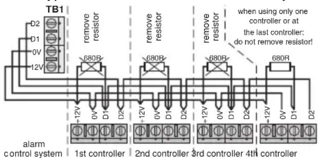
TB1 D2 D1 0V 12V remove resistor 680R remove resistor 680R remove resistor 680R when using only one controller or at the last controller: do not remove resistor! -12V 0V D1 D2 -12V 0V D1 D2 -12V 0V D1 D2 -12V 0V D1 D2 alarm control system 1st controller 2nd controller 3rd controller 4th controllerFig. 3 Connection of the keypad controllers
When connecting several keypad controllers, remove the 680 Ω terminating resistor between the contacts “+12V and “D1”, however, not at the last keypad controller.
5) Shortly apply the mains voltage to the alarm control system (chapter 4.5.12) so that the display lights up. Adjust the contrast of the display in an optimum way with the control on the rear side of the keypad controller. Then tightly screw the front part to the housing frame.
4.5 Making the connections
The following fig. 4 shows all possible connections. Detailed information can be found in chapters 4.5.1 to 4.5.12.
flowchart
graph TD
    A["max. 4 keypad controllers"] --> B["12 V rech. batt."]
    B --> C["T2A from the mains transformer"]
    C --> D["T8S"]
    D --> E["T1B1"]
    D --> F["T8B3"]
    D --> G["T8B4"]
    D --> H["T8B5"]
    D --> I["T8B6"]
    D --> J["T8B7"]
    D --> K["T8B8"]
    D --> L["T8B9"]
    D --> M["T8B10"]
    D --> N["T8B11"]
    D --> O["T8B12"]
    D --> P["T8B13"]
    D --> Q["T8B14"]
    D --> R["T8B15"]
    D --> S["T8B16"]
    D --> T["T8B17"]
    D --> U["T8B18"]
    D --> V["T8B19"]
    D --> W["T8B20"]
    D --> X["T8B21"]
    D --> Y["T8B22"]
    D --> Z["T8B23"]
    D --> AA["T8B24"]
    D --> AB["T8B25"]
    D --> AC["T8B26"]
    D --> AD["T8B27"]
    D --> AE["T8B28"]
    D --> AF["T8B29"]
    D --> AG["T8B30"]
    D --> AH["Sirobelight, 12 V=, max. 250 mA*"]
    D --> AI["siren, 12 V=, max. 500 mA*"]
    D --> AJ["anti-tamper contact for siren + strobelight"]
    D --> AK["programmable control output* (internal) speaker minimum impedance 16Ω"]
    D --> AL["12 V operating voltage for external units*"]
    D --> AM["anti-tamper contacts for all alarm sensors"]
    D --> AN["alarm zone 1 for NC contacts"]
    D --> AO["alarm zone 2 for NC contacts"]
    D --> AP["alarm zone 3 for NC contacts"]
    D --> AQ["alarm zone 4 for NC contacts"]
    D --> AR["key switch or alarm zone 5"]
    D --> AS["alarm zone 6 for NC contacts"]
    D --> AT["alarm zone 7 for NC contacts"]
    D --> AU["alarm zone 8 for NC contacts"]
*The current rating of all consumers connected must not exceed a total of 1 A!
text_image
230 V connection mains fuse T125mA phase (brown) earthed conductor (green/yellow) [not required] neutral conductor (blue)Fig. 4 Overview of the connections
Hints
- All alarm contacts shown in fig. 4 are opening contacts (also called NC contact = normally closed) as for the majority of the standard components. Generally it is also possible to use closing contacts (NO contacts = normally open). As an exam-
ple of connection a raid detector is indicated in chapter 4.5.7. Within a loop, only use one contact type.
- For activating or deactivated the alarm control system via a key switch, the alarm zone "AZ5" must be reserved for this purpose.
- Please always exactly observe the installation instructions of the components used.
4.5.1 Speaker
Connect the supplied speaker or another 16 Ω speaker to the contacts “+ SPKR -” of the terminal strip TB4 (6).
4.5.2 Alarm unit or individual strobelight and siren
For visual and acoustical alarm either connect an alarm unit consisting of a strobelight and a siren or connect these components as individual units to the terminal strip TB3 (5):
text_image
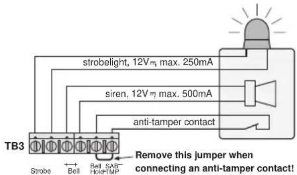
strobelight, 12V=, max. 250mA siren, 12V=, max. 500mA anti-tamper contact TB3 Strobe + Bell Bell SAB- Hold-TMP Remove this jumper when connecting an anti-tamper contact!Fig. 5 Connection of an alarm unit
WARNING
Most alarm units and sirens produce a very high sound level. Alarm devices with a rechargeable battery (independent power supply) immediately respond when the rechargeable battery is connected. Therefore, in any case put on a hearing protection before connecting it.

Important!
The current rating of these consumers and that of the contacts "PGM1" and "AUX 12V" of the terminal strip TB4 (6) must not exceed a total of 1 A!
4.5.3 Opening sensors for windows and doors
Reed contacts are used for alarm triggering when opening a window or a door. These consist of an opening contact which is normally closed by a magnet. When opening e.g. a door, the magnet withdraws from the contact so that the contact will be opened. The alarm loop will be interrupted and the control system will trigger alarm.
Fig. 6 shows the connection of opening sensors on the next page.
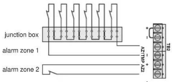
text_image
junction box alarm zone 1 alarm zone 2 A1TMP AZ2 + - TB2Fig. 6 Opening detectors (reed contacts) for windows and doors
Important!
When connecting NC contacts to an alarm zone, remove the corresponding jumper between the contacts "AZ" in any case, otherwise no alarm can be triggered.
Hints
- When connecting several detectors to an alarm zone, use a junction box (see fig. 6, alarm zone 1).
- Use a separate alarm zone for the main access door and for this activate the delay times for the entry and exit (see chapter 5.2). Thus, the operating personnel will be able to activate the system and leave the building through the main door within the delay time or switch off the system after entering the building without triggering an alarm.
4.5.4 PIR motion detectors
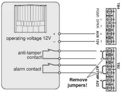
Passive infrared motion detectors detect the movement of infrared heat sources, e. g. of living beings. In most cases they are equipped with an NC contact which is opened with a movement recognized.
text_image
operating voltage 12V anti-tamper contact alarm contact Remove jumpers! PGM1 SPKR AUX 12V + - + - + - AZTMP AZ2 TB4 TB2Fig. 7 PIR motion detector with opening contact (NC contact)
4.5.5 Fire and smoke detectors
It is also possible to connect fire and smoke detectors to the alarm control system. Programme the alarm zone for these detectors to "Fire" (chapter 5.1). Thus, in case of danger persons present are warned by a pulsating alarm tone even if the alarm system is deactivated.
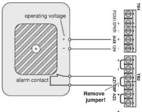
text_image
operating voltage + - alarm contact PGM1 SPKG AUX 12V + - A27MP A22 Remove jumper! TB4 TB2Fig. 8 Fire or smoke detector with opening contact (NC contact)
4.5.6 Glass break detectors
Glass break detectors serve for alarm triggering when breaking a glass pane.
Passive glass break detectors are directly glued to the glass pane and interrupt the current flow in an alarm loop for triggering alarm. They are connected the same way as the reed contacts for windows and doors (chapter 4.5.3).
Acoustical glass break detectors react on the typical noise caused by bursting glass. They require a supply voltage for operation.
text_image
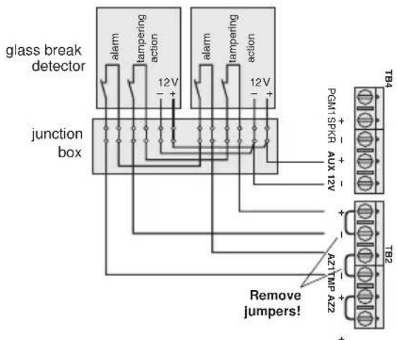
glass break detector junction box alarm tampering action 12V + - alarm tampering action 12V + - Remove jumpers! PGM1SPKR AUX 12V + - A2TMP AZ2 + - TB4 TB2Fig. 9 Acoustical glass break detectors
4.5.7 Raid detectors (panic button)
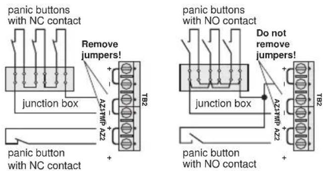
Raid detectors are connected to a separate alarm loop which is programmed to "Panic" (chapter 5.1). Thus, it is possible to trigger an alarm manually via this detector by actuating the panic button even if the system is deactivated.
text_image
panic buttons with NC contact Remove jumpers! + - A21TMP A22 junction box + - T82 panic button with NC contact + - panic buttons with NO contact Do not remove jumpers! + - A21TMP A22 junction box + - T82 panic button with NO contactFig. 10 Raid detector (panic button)
For detectors with NC contacts the jumper between the corresponding connections "AZ..." must be removed. For detectors with NO contacts leave this jumper inserted in any case and connect the contacts of the detector to one of the contacts "AZ..." of the corresponding alarm zone and to the contact "TMP—" of the terminal TB2!
4.5.8 Key switch or code lock
Only a type with pulsed contact (momentary NC push-button) can be used as a key switch (e. g. the model NSA-80 from MONACOR). As an alternative it is also possible to use a corresponding code lock (e. g. DAC-299 from MONACOR). Via this code lock the alarm control system is activated or deactivated by entering a code number. The switch or the lock must be connected to the alarm zone "AZ5". Programme this zone to "Key" (chapter 5.1) and "Full" (chapter 5.2). Thus, also the exit delay time is at the same time activated when setting the system. It is not possible to connect other components to this zone in this case.
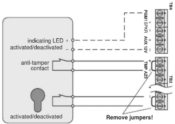
flowchart
graph TD
    A["indicating LED"] --> B["activated/deactivated"]
    B --> C["anti-tamper contact"]
    C --> D["T82"]
    D --> E["Remove jumpers!"]
    F["PGM1 SPKR"] --> G["AUX 12V"]
    G --> H["T84"]
Fig. 11 Key switch
If the key switch has a status indication (system activated/deactivated), it can be connected to the contacts "PGM1" and "AUX 12V-" of the terminal TB4. Then the control output "PGM1" must be programmed accordingly (chapter 5.4).
4.5.9 Telephone dialling unit
An automatic telephone dialling unit is a silent alarm device which in case of alarm automatically dials a phone number programmed before.
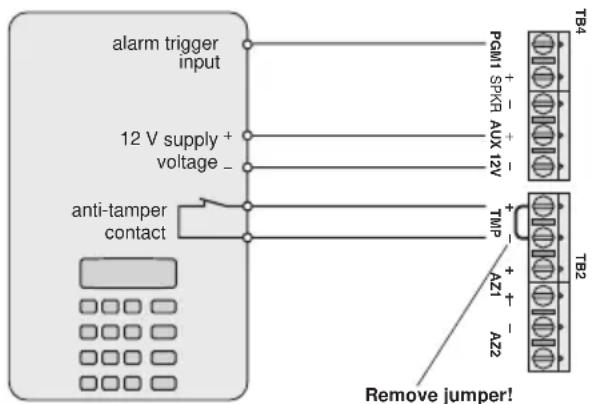
text_image
alarm trigger input 12 V supply + voltage _ anti-tamper contact PcM1 SPKR AUX 12V T84 + - + - TMP + - AZ1 AZ2 TB2 Remove jumper!Fig. 12 Automatic telephone dialling unit
The control output "PGM1" of the terminal TB4 should be programmed with the function "alarm" (chapter 5.4).
4.5.10 Guiding the anti-tamper loops of the alarm zones to the connection TMP
Combine the anti-tamper loops of all alarm zones as follows and connect them to the contact TMP of the terminal TB2 (9):
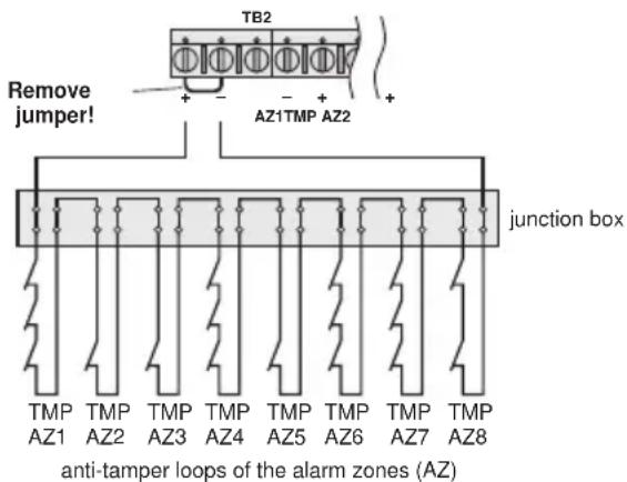
text_image
TB2 Remove jumper! AZ1TMP AZ2 junction box anti-tamper loops of the alarm zones (AZ)Fig. 13 Connection of anti-tamper loops of all alarm zones
4.5.11 12 V rechargeable battery
For emergency power supply in case of a mains failure and for power supply of an alarm unit in case of alarm a 12 V rechargeable battery with a minimum capacity of 2 Ah (e. g. NPA-12/7 from MONACOR) must be inserted. Connect the red cable lug (13) to the positive pole of the rechargeable battery and the black cable lug (12) to the negative pole. Accommodate the rechargeable battery into the space provided (19).
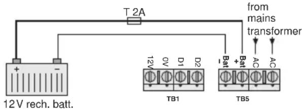
text_image
T 2A from mains transformer 12V rech. batt. TB1 TB5Fig. 14 12 V rechargeable battery
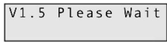
After connection of a rechargeable battery charged the display of the keypad controller shortly shows the version number of the software and the request to wait:
Then the display shows:
Normally the rechargeable battery is charged via the internal charging part. A slow-blow 2 A fuse in the holder (14) serves as a protection. To replace the fuse, unscrew the holder.
4.5.12 Mains voltage
Connect the 230 V power supply of the alarm control system to the terminal block on the bottom left (positions 16 to 18):
Neutral conductor to the lower terminal
Earthed conductor to the central terminal – however, the earthed conductor must not be connected because the alarm control system corresponds to protective
class II. The terminal only serves for fixing an earthed conductor which may exist.
Phase to the upper terminal; the mains fuse (15) is located exactly above it
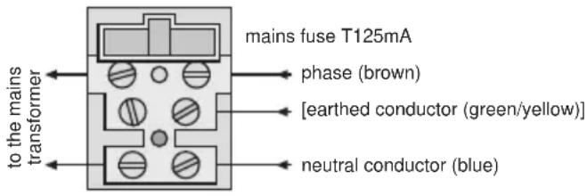
text_image
to the mains transformer mains fuse T125mA phase (brown) [earthed conductor (green/yellow)] neutral conductor (blue)Fig. 15 Mains connection
As soon as the mains voltage is applied, the LED1 (7) shows green.
Important!
After all connections have been made, place the housing cover of the alarm control system and tightly screw it so that the anti-tamper contact (11) will be closed and no alarm will be triggered!
5 Programming
Programming is possible from each connected keypad controller. If you are already quite familiar with the programming, you can proceed by means of the overview of the programme menu on the two separate DIN A3 sheets supplied. The best thing is to enter all settings made on the last page of these instructions and on the last page of the operating instructions so that yourself and the operators will always be informed about all parameters.
Make sure that no unauthorized persons get hold of the installation instructions, the operating instructions, and the menu overview!
5.1 Programming the features of the zones
First programme each zone separately for the required features. The feature is composed of the alarm response and the mode.
- Alarm response (type) -
12 Hr
In case of an alarm recording the zone immediately triggers alarm if the alarm control system is activated (standard setting without extra function).
E/E (entry/exit)
After activating the alarm control system, the zone is not activated until the exit delay time (exit time) has expired. In case of an alarm recording it only responds after the entry delay time (entry time) has expired. This feature is especially provided for the doors through which the operators of the alarm control system enters and leaves the building. For programming the delay times see chapter 5.2.
Access
In case of alarm recording in this zone no alarm will be triggered if another zone with the feature E/E has activated the entry delay before. However, if this delay was not activated, a recording will immediately trigger alarm. This feature is especially provided for motion detectors intended for the access doors for the operators.
Panic
The zone always immediately triggers alarm in case of an alarm recording even if the alarm control system is deactivated. This feature is especially provided for raid detectors (panic button).
24 Hr
The zone always immediately triggers alarm in case of an alarm recording. If the alarm control system is deactivated, the alarm triggering is only made via the buzzers of the keypad controllers and via the speaker. With the system activated, the siren connected is additionally activated.
Fire
In case of an alarm recording the zone always immediately triggers alarm even if the alarm control system is deactivated. To recognize the fire alarm, a siren connected will sound in a pulsed way. This feature is especially provided for smoke and fire detectors.
Alert
With the system deactivated and an alarm recording, the buzzers of the keypad controllers and the speaker will sound. This feature is especially provided for doors which are to be kept closed when present (e.g. emergency doors or fire doors). With the system activated, this zone is excluded from the alarm recording.
ET (Exit Terminator)
The exit delay time in the zones with the setting E/E is only terminated when a recording is made in the "ET" zone. The function "ET" has to be programmed in the system setting for the mode of the exit delay (exit mode) [see chapter 5.2, step 22]. However, an alarm cannot be triggered by an "ET" zone. This feature is especially provided for systems for which the operators need more than 99 seconds to leave the last zone after activation.
Pt E/E (Part Entry/Exit)
If only a part of the alarm system is activated, this zone responds like a zone with the feature E/E. If the complete system is activated, this zone has the feature "Access".
Key
This function is especially provided for a key switch or a code lock with pulsed contact (momentary pushbutton) and can only be programmed for the zone 5. For the mode, "Full" must be programmed (see operating step 14). Also the exit delay time is activated by these settings when activating via the key switch.
As soon as the function "Key" has been programmed, the zone 5 is no longer suitable for the connection of alarm sensors.
- Mode -
Part 1
If the alarm control system in the mode "Part 1" is partially activated, a recording in one zone with the mode "Part 1" or "Part 3" does not trigger an alarm. Thus, e.g. motion detectors inside the building can be excluded from the alarm recording when authorized persons are present in their monitoring area. However, a recording in zones with another mode triggers alarm (e.g. by an opening detector at a window).
Part 2
Corresponds to the feature "Part 1", however, in the mode "Part 2", zones with the mode "Part 2" or "Part 3" are excluded from alarm triggering.
Part 3
If the alarm control system is partially activated in mode "Part 3", a recording in the zones with the mode "Part 1", "Part 2", or "Part 3" does not trigger an alarm.
Chime
If the alarm control system is deactivated and an alarm is recorded in this zone, the buzzers in the keypad controllers and the speaker are able to emit four short audio signals. This function can be switched on and off for all "Chime" zones together via the keypad controller (see operating instructions).
With the alarm control system activated and an alarm recording in a “Chime” zone always all signal devices are normally activated.
Ch/P1
If the alarm control system is deactivated and an alarm has been recorded in this zone, the buzzers in the keypad controllers and the speaker can emit four short beep tones (also see mode "Chime"). With the alarm control system activated in mode "Part 1" or "Part 3" and an alarm recording in this zone no alarm will be activated.
Ch/P2
Same as Ch/P1, however, with the alarm control system activated there will be no alarm triggering in the mode "Part 2" or "Part 3".
Ch/P3
Same as Ch/P1, however, with the alarm control system activated there will be no alarm triggering in the mode "Part 1", "Part 2", or "Part 3".
Full
With the alarm control system activated and an alarm recording in this zone all signal devices are normally activated (standard setting without extra function).
- Operating steps -
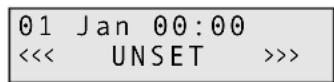
1) After applying the voltage of the rechargeable battery or mains voltage, the display of the keypad controller shows:
| 01 Jan 00:00 | ||
| << | UNSET | >>> |
The alarm control system is not activated. To switch to the programming mode, enter the 4-digit programming code (default setting: 1, 2, 3, 4) with the numerical keys. Each pressing of the buttons is confirmed by a short beep tone. After entering the programming code, another audio signal sounds and the display shows:
| Do You Want to.. Set Engineer ? |
2) Press the button No within 15 seconds, otherwise the programming mode will be exited. The display shows:
| Do You Want to..Test ? |
3) Press again the button No. The display shows:
| Do You Want to..Delete Zone ? |
4) Press the button No once more. The display shows:
| Do You Want to..Select Options ? |
5) Press the button Yes. The display shows:
| Do You Want to..Program Chime ? |
6) Press the button No. The display shows:
| Do You Want to..Program Codes ? |
7) Press the button No again. The display shows:
| Do You Want to.. Set Date/Time ? |
8) Press the button No once more. The display shows:
| Do You Want to..View Log ? |
9) Press the button No. The display shows:
| Program | ...... |
| Zones ? |
10) Press the button Yes. The display shows:
| Select | 1..8 |
11) Enter the number of the zone to be set, e. g. button "1" for zone 1. The display shows:
| Zone | 1 | Type |
| E/E |
12) Press the button No so many times until the required type of the alarm response (type) is shown: 12 Hr, E/E, Access, Panic, 24 Hr, Fire, Alert, ET, Pt E/E, or Key. If the zone is to trigger alarm e. g. also with deactivated alarm control system:
| Zone 1 Type24 Hr |
13) To confirm press the button Yes. The display shows e.g.:
| Zone | 1 | Mode |
| Chime |
14) Press the button No so many times until the required mode is shown: Part 1, Part 2, Part 3, Chime, CH/P1, CH/P2, CH/P3, Full For activating this zone both in the full activation mode and partial activation mode:
| Zone | 1 | Mode |
| Full |
Note: If the key function is selected for the zone 5, the mode "Full" must be programmed.
15) To confirm press the button Yes. The display e.g. shows:
Zone 1 Text Zone1
16) The characteristic of the zone is shown in the lower display line. The default setting is: "Zone" and the number of the zone. For keeping the default setting press the button Yes and continue with the operating step 19.
For indicating another characteristic press the button No. The display shows:
Zone 1 Text
17) With the numerical keys enter 16 letters, numbers, and, if necessary, blanks. Press the corresponding numerical key so many times until the desired character appears:
| Button | Character |
| 1 A, | B, C |
| 2 D, | E, F |
| 3 G, | H, I |
| 4 J, | K, L |
| 5 M, | N, O |
| Button | Character |
| 6 P, | Q, R |
| 7 | S, T, U |
| 8 | V, W, X |
| 9 | Y, Z, blank |
| 0 | 1, 2, 3, ... 9, 0 |
If the desired character is displayed, actuate the button Yes and enter the next letter. If not all 16 characters are required, complete the remaining positions with blanks.
18) As soon as the 16th character is confirmed with the button Yes, the display goes to the settings for the next following zone. Repeat the operating steps 12) to 17) for all zones used.
19) To exit the level for the zone settings, press the button 0. The display shows:
Program ..... Zones ?
5.2 Entry delay and exit delay Signalizing when activating Quick activation
20) Starting from the operating step 19) of the previous chapter press the button No. The display shows:
Program ...... Exit/Entry ?
21) Press the button Yes. The display shows:
F-Exit Time 30
“F-Exit Time” is the exit delay time in the activation mode “Full” (all zones activated). 30 seconds are programmed as a default setting. For keeping this delay time press the button Yes.
To programme another time, press the button No. The display changes to:
F - Exit Time 0 0 ←
Enter a time between 00 and 99 seconds with the numerical keys. A wrong input can be corrected by writing over it.
22) To confirm the selected time, press the button Yes The display changes to:
F-Exit Mode Time
Press the button No so many times until the required mode for the exit delay time is displayed:
Time
The exit delay time ends after the time adjusted before.
T/EE (Time or Entry/Exit)
The exit delay time either ends after the time adjusted before or if a recording was made in a zone with the feature "E/E".
ET (Exit Terminator)
The exit delay time will not end before a recording is made in the zone with the feature "ET".
E/E (Entry/Exit)
The exit delay time will not end before a recording is made in a zone with the feature “E/E”.
23) To confirm the selected mode, press the button Yes. The display changes to:
P-Exit Mode Time
"P-Exit Time" is the exit delay time in the activation mode "Part..." (certain zones are deactivated). 30 seconds are programmed as a default setting. For keeping this delay time, press the button Yes.
Another time and the mode for the exit delay time are programmed as for the activation mode "Full" (see operating steps 21 and 22).
24) To confirm the selected mode, press the button Yes. The display changes to:
P-Exit Sounder Aud.
Press the button No so many times until the desired mode for the acoustical signaling of the exit delay time in the activation mode "Part ..." is displayed:
Aud.
During the exit delay time an audio signal sounds continuously. Adjust the volume for the speaker with the control VR1 (8). However, in case of an alarm the speaker will always sound at maximum volume.
Silent
During the exit delay time no audio signal will sound. When the time has expired, however, a short signal will sound.
P1 Aud.
The signal will only sound in the activation mode "Part 1" and "Part 3" during the exit delay time.
P2 Aud.
The signal will only sound in the activation mode "Part 2" during the exit delay time.
The acoustical signaling is made via the buzzers of the keypad controllers and via the speaker.
25) To confirm the selected mode, press the button Yes. The display changes to:
Confirm Mode
Off
Press the button No so many times until the desired visual confirmation of the activation is displayed:
Off
There is no visual signaling if the alarm control system is activated.
Any
As soon as the alarm control system is activated (both in the mode "Full" and in one of the modes "Part ...") the connected strobelight will be activated for some seconds.
Full
Only after the alarm control system is activated in the mode "Full", the strobelight will be activated for some seconds.
26) To confirm the selected mode, press the button Yes. the display changes to:
Quick Set
On
With this adjustment the alarm control system can also be activated with the button Quick at one keypad controller even without entering a user code. For keeping this adjustment press the button Yes.
To deactivate this activation facility, press the button No. The display shows:
Quick Set
0ff
27) To confirm the selected adjustment, press the button Yes. The display changes to:
Entry 1 Time
30
Here the entry delay time is programmed which is composed of two partial times. This delay time is available to the operators when crossing an "E/E" zone to deactivate the zone without triggering alarm. While the first partial time is running (Entry 1 Time, default setting 30 seconds), the buzzers of the keypad controllers and the speaker signalize a pulsating tone. Then the second partial time starts (Entry 2 Time, default setting 10 seconds). An audio signal of a different sound now warns that the end of the entry delay time is coming near. The alarm control system must be deactivated before, otherwise an alarm will be triggered.
For keeping the default setting for the first partial time (30 seconds) press the button Yes. Otherwise press the button No and enter the desired time with the numerical keys with two digits.
28) To confirm the first partial time, press the button Yes. The display changes to:
Entry 2 Time
10
Proceed the same way with the second partial time.
29) To confirm the second partial time, press the button Yes. The display returns to:
F-Exit Time
30
Program .....
Exit/Entry ?
5.3 Settings for the alarm triggering and the panic button
30) Starting from operating step 29) of the previous chapter press the button No. The display shows:
Program ......
Bell & Panic ?
31) Press the button Yes. The display shows:
Ring Time 20
The time for the acoustical alarm is preset to 20 minutes. However, the strobelight is activated until the alarm control system is deactivated again.
Important!
If it siren is installed outdoors, the siren time must be limited in some countries (in Germany to 3 minutes as a maximum). Longer alarm times may be reported to the police because of a disturbing noise.
To programme another time, press the button No. The display changes to:
Ring Time
0 0 <
Enter the siren time in minutes with the numerical keys.
Ring Time
03←
32) To confirm the selected setting, press the button Yes. The display changes to:
Bell Delay
00
There is no default setting of the response delay time for the visual and acoustical alarm triggering. For keeping this setting press the button Yes.
To programme a delay, press the button No. The display shows:
Bell Delay
0 0 ←
Enter the delay time in minutes with the numerical keys. A delayed response is e. g. useful for triggering a silent alarm via the telephone dialling unit first.
33) To confirm the selected setting, press the button Yes. The display changes to:
Bell Re-Arms 99
Here the alarm repeat is programmed, i. e. how many times a response of the siren is repeated after its alarm time has expired and another recording is made in a zone but the alarm has not yet been reset. 99 repeats are preset. For keeping this setting press the button Yes.
For an outside siren, however, the setting 00 (no repeat) is recommended so that no unnecessary disturbing noise occurs. For this purpose press the button No. The display shows:
Bell Re-Arms
00←
Either press the button Yes for no repeat or first enter the desired number with the numerical keys and then press the button Yes. The display changes to:
Bell Mode SAB
34) Select the siren type. SAB (self actuating bell) is preset, i. e. for sirens without time limit of their own. For the time of the acoustical alarm triggering a 12 V voltage is applied at the connections "Bell" of the terminal TB3 (5). To confirm this setting, press the button Yes or for selection of the type SCB (self contained bell = siren with time limit and power supply of its own) press the button No. The display changes to:
Bell Mode
SCB
With this setting a 12 V control voltage is applied at the connections "Bell" if no alarm is present. This voltage drops in the alarm mode. Then the siren will sound until the time adjusted at it has expired. The advantage of this siren type is that in case of tampering actions the siren immediately and independently responds due to the missing control voltage when the siren control cable is cut. The model SAG-14 and an additional relay of the product range from MONACOR are recommended for this purpose.
35) To confirm the setting, press the button Yes. The display changes to:
Tamper Ring
Off
If the anti-tamper contact of the siren (or the alarm unit) is opened and if the alarm control system is deactivated, only the buzzers of the keypad controllers and the speaker will sound (with activated alarm control system of course additionally the strobelight and siren). For keeping this setting press the button Yes.
However, for additional response of the strobelight and the siren in any case, switch with the button No to:
Tamper Ring
On
36) To confirm the setting, press the button Yes. The display changes to:
Panic Mode On
If an alarm is triggered via a connected panic switch, this setting results in a visual and acoustical alarm triggering. For keeping the setting press the button Yes.
However, for a silent alarm only (signalizing only via the display of the keypad controllers and, if required, via the control output PGM1 – see chapter 5.4), press the button No. The display changes to:
Panic Mode Sil.
37) To confirm the selected setting, press the button Yes. The display returns to:
Ring Time 20
To exit this menu level, press the button 0. The display shows:
Program ......
Bell & Panic ?
5.4 Control output PGM1
38) Starting from operating step 37) of the previous chapter press the button No. The display shows:
Program ..... Output & Digi ?
39) Press the button Yes. The display shows:
PGM 1 Mode
SW12V
Select the function for the control output PGM1 of the terminal TB4 (5). The respective voltage is always measured against the connection "AUX 12 V−". "SW12V" is preset, i. e. with the alarm control system activated the output voltage goes from 0 V to 12 V (already while the exit delay time is running). For keeping this setting press the button Yes.
To select another function, press the button No so many times until the display shows the corresponding indication:
Puls+
When activating, the voltage goes from 0 V to 12 V for approx. 3 seconds (already while the exit delay time is running).
Bell
As long as the siren sounds, 12 V are present.
Strb.
As long as the strobelight is activated, 12 V are present (even if the strobelight is only shortly activated to confirm the activation).
EX/EN
12 V are present while the entry delay time or exit delay time is running.
Walk
As long as the test mode (walk testing ...) is activated, 12 V are present.
IntAI
In case of alarm triggering 12 V are present until the alarm is reset via the keypad controller (also when triggering a “panic” zone or “alert” zone).
Alarm
During an alarm triggering 12 V are present until the alarm is reset (not when releasing a “panic” zone or “alert” zone).
Panic
If a zone with the feature "Panic" has been activated, 12 V are present until the alarm is reset.
Puls-
When activating, the voltage goes from 12 V to 0 V for approx. 3 seconds (already while the exit delay time is running).
40) To confirm the selected setting, press the button Yes. The display changes to:
| Chan.1 | Mode |
| Fire |
This menu item is not required for the DA-8000. Please do not change the setting "Fire".
41) Press the button Yes. The display changes to:
| Alarm | Restore |
| Off |
Also this menu item is not required for the DA-8000. Please do not change the setting "Off".
42) Press the button Yes again. The display returns e.g. to:
| PGM 1 ModeSW12V |
To exit this menu level, press the button 0. The display shows:
| Program .....Output & Digi ? |
5.5 Alarm reset authorization and alarm triggering via the keypad controller
43) Starting from the operating step 42) of the previous chapter press the button No. The display changes to:
| Program .......Reset & Keypad ? |
44) Press the button Yes. The display shows:
| Tamper | Reset |
| Any |
Here the alarm reset authorization while recording a tampering action is programmed. The default setting is that in case of tampering actions the alarm is terminated by entering a desired access code. For keeping this setting press the button Yes.
For the option "Eng" (Engineer), press the button No once. The display shows:
| Tamper | Reset |
| Eng |
With this setting the acoustical signaling can also be terminated with any access code, however, then the display shows:
| !! SERVICE DUE ! |
This is to indicate that a technician has to repair the damage caused by tampering first before the alarm control system can be reactivated.
45) To confirm the setting, press the button Yes. The display changes to:
| Alarm | Reset |
| Mast |
Here the alarm reset authorization after an alarm triggering is programmed. The default setting is that the alarm can only be terminated by entering a master code (default setting: 5, 6, 7, 8) and by pressing the button Reset subsequently. For keeping this setting press the button Yes.
To select another authorization, press the button No so many times until the corresponding indication is displayed:
Anti (anti code reset)
The alarm triggering can in fact be terminated by entering a master code (default setting: 5, 6, 7, 8). However, the alarm cannot be reset with the button Reset so that the alarm control system cannot be reactivated. For this purpose a special software and a PC are required.
Eng. (engineer)
The acoustical signaling can in fact be terminated with a desired access code, however, the alarm can only be reset with the button Reset after entering the access code for programming previously (default setting: 1, 2, 3, 4).
Any
The alarm can only be reset by entering a desired access code and pressing the button Reset subsequently.
46) To confirm the authorization, press the button Yes. The display changes to:
Service Time 99
Attention!
Do not change this default setting "99" (99 = timer off), otherwise the service timer will be started. If this has expired, the alarm control system can only be reactivated if the timer was reset before. For this purpose a special software and a PC are required!
If the timer is started by entering another number, it counts the time (in weeks) up to the next servicing.
47) Press the button Yes. The display changes to:
Alert Mode Panic
It is possible to select at this menu item which alarm type is triggered by simultaneously pressing the numerical keys 1 and 3 at a keypad controller:
Panic
With this setting an alarm is immediately triggered by pressing the keys 1 and 3 simultaneously, even is the alarm control system is deactivated. This function can thus be used as raid detector (panic switch).
Fire
With this setting a fire alarm is immediately triggered by pressing the keys 1 and 3 simultaneously, even if the alarm control system is deactivated. To recognize the fire alarm, a siren connected will sound in a pulsed way. This function can thus be used as a fire detector.
Alert
Only with deactivated alarm control system an alarm is triggered by pressing the keys 1 and 3 simultaneously. However, this is only signalized by the buzzers of the keypad controllers and the connected speaker. Thus, this function can e.g. serve as internal emergency detector.
Off
No function is triggered by pressing the buttons 1 and 3 simultaneously.
5.6 Terminating the programming mode
Unless it is expected to enter a number as the next operating step, independent of the actual menu level press the button 0 so many times until an audio signal confirms the termination of the programming mode and the display again shows date, hour, and <<< UNSET >>>.
5.7 Changing the access code for programming
Two access codes are factory-set:
-
Access code for activating/deactivating and calling the operating menu (master code); default setting: 5, 6, 7, 8 for the user No. 1. Via this code up to eight further access codes for activating/deactivating with different access authorization can be provided (see operating instructions).
-
Access code for programming; default setting: 1, 2, 3, 4. This can be changed as follows:
1) The alarm control system must be deactivated. Enter the access code for programming which is valid at present. The display shows:
Do You Want to.. Set Engineer?
2) Press the button No within 15 seconds, otherwise the programming mode will be exited. The display shows:
Do You Want to..
Test ?
3) Press the button No two more times. The display must now show:
Do You Want to.. Select Options ?
4) Press the button YES. The display shows:
Do You Want to.. Program Chime?
5) Press the button No. The display shows:
Do You Want to.. Program Codes?
6) Press the button Yes. The display shows:
Code
7) Press the button No. The display shows:
Code 0000
8) Enter the new access code with the numerical keys:
Important!
The access code is set to 1, 2, 3, 4 again while resetting to the factory default (chapter 5.9), however, it is not reset if it starts with 9. Such a code can, however, be changed in the programming mode again but make sure to remember it!
To confirm the code entered, press the button Yes. The display returns to:
Do You Want to.. Program Codes ?
9) To exit the programming level, press the button 0 twice so that date, hour, and <<< UNSET >>> are displayed again.
5.8 Changing the mode for the log
It is possible to store respectively:
A the last 64 events with date and hour (factory default) or
B the last 256 events without indication of date and hour
Attention!
By changing the mode setting all previous events are deleted. This procedure is indicated in the log as entry "L/Rst" (Log Reset).
1) Disconnect the mains voltage and the rechargeable battery or simply remove the corresponding fuses (14 and 15).
2) Wait for at least 10 seconds.
3) Apply the mains voltage again. (Insert mains fuse again).
4) As soon as the display shows "V... Please Wait", for the option B of 256 events: press the buttons 0, 0, 7, No or
for the option A of 64 events:
press the buttons 9, 1, 7, No. This setting is kept even when resetting to the factory default.
The entry must be terminated even before the display switches to the indication of date, hour, and <<< UNSET >>>, otherwise the mode will not be changed. A change of the mode is neither indicated acoustically nor visually.
5) Apply the voltage of the rechargeable battery again.
5.9 Resetting to the factory default
When supplied, the alarm control system is programmed to the values of the factory default. These values are indicated on page 39. If required, the alarm control systems can be reset to this factory default. The log is not deleted by this.
1) Disconnect the mains voltage and the rechargeable battery or simply remove the corresponding fuses (14 and 15).
2) Wait for at least 10 seconds.
3) Apply the mains voltage again (insert mains fuse again).
4) As soon as the display shows "V... Please Wait", press the buttons 1, 4, 7, No. The entry must be terminated even before the display switches to the indication of date, hour, and <<< UNSET >>>, otherwise no resetting will be made. The resetting is neither indicated acoustically nor visually.
5) Apply the voltage of the rechargeable battery again.
5.10 Further information on the operation
Further information is indicated in the operating instructions especially made for the operators of the alarm control system:
- Change the access code for the operators and provide further codes (if necessary with different access authorization)
- Adjust the time and the date
- Switch on and off the function "Chime"
- Activate or partially activate the alarm control system and deactivate it again
- Exclude certain zones from the alarm recording
- Meaning of the alarm messages displayed
- Resetting the alarm
- Reading the log
6 Test Mode
The complete alarm system should be checked after programming. For this purpose all alarm sensors can successively be triggered in the test mode without response of the siren and the strobelight.
1) The system must be deactivated. Enter the access code for programming which is valid at present (default setting: 1, 2, 3, 4). The display shows:
Do You Want to.. Set Engineer?
2) Press the button No within 15 seconds otherwise the programming mode is exited. The display shows:
Do You Want to..
Test ?
3) Press the button Yes. The display must now show:
Walktesting.....
Ok!
4) Trigger all sensors and detectors successively. The buzzers of the keypad controllers and the speaker will sound for the time of the alarm recording. During this time the display shows the corresponding zone.
5) To test the siren and the strobelight, press the numerical key 9. To switch off, press the key 9 again.
6) To switch off the test mode and to exit the programming mode, press the button 0 three times so that date, time, and <<< UNSET >>> are shown again.
Important!
The programming (delay times, zone features, etc.) cannot be checked in the test mode. For this purpose the alarm control system must be activated. To prevent a disturbing noise, the siren should be disconnected during this test.
Always reconnect the siren again after the test!
7 Trouble Shooting
The LED for indicating the mains voltage (7) does not light up
Check the mains connection and the mains fuse (15).
No indication in the display of the keypad controller (off) Check the fuse F2 (3), the correct connection (chapter 4.4), and the connection cables to the keypad controllers. Is the control for the display contrast on the rear side of the keypad controller correctly adjusted?
The exit delay time does not terminate after the activation and the display shows an open loop (zone ...), although all alarm contacts are closed
Remove the lines for the zone indicated from the terminal strip TB2 (9) and replace them by a jumper (e.g. contacts AZ5 + - in case of the indication "zone 5"). If the alarm control system can now be activated without problems, the error is either due to a defective alarm sensor or due to an interrupted connection line. Locate the error with a continuity tester.
In case of a short circuit between the connection cable of the zone and the connection cable for the anti-tamper loop (contacts TMP + -) an alarm is likewise indicated.
When using NO contacts, the factory-set jumper must not be removed (fig. 10 on the right)!
Tampering actions are shown on the display:
Case Tamp = The anti-tamper contact of the alarm control system is opened
KP Tamper = The anti-tamper contact of a keypad controller is opened
Bell Tamp = The anti-tamper contact of the alarm unit (or of the siren or strobelight) is opened
Tamper = One of the contacts in the common anti-tamper loop of the sensors (connections "TMP" of the terminal TB2) is opened
Is the corresponding housing correctly closed? Is the spring on the anti-tamper contact correctly placed? Is the cable of the anti-tamper loop interrupted? Has this cable a short circuit to another connection? Is the service timer expired?
By activating an alarm sensor or by opening an alarm contact no alarm can be triggered
For NC contacts: Are all contacts connected in series? (see figs. 4 and 6). If only one is connected in parallel, it is not possible to record via this contact and the contacts following it! Has the factory-set jumper been removed? Has the zone correctly been programmed?
For NO contacts: Are all contacts connected in parallel and are they correctly connected? (see fig. 10 on the right). If only one is connected in series, it is not possible to record via this contact and the contacts following it! Has the zone correctly been programmed?
For alarm sensors supplied with 12 V: Measure at the contacts AUX 12V of the terminal TB4 (6) if 12V are present. If not, check the fuse F1 (3) and replace it, if necessary. The current load of all consumers connected must not exceed a total of 1 A, otherwise this fuse will melt again (also see fig. 4). Check the connection cables to the detector not responding for interruption and short circuit.
The siren or flashlight does not respond.
Check the fuse F1 (3), the correct connection (chapter 4.5.2) and the connection cables for these components. To exclude a defect of the siren and strobelight, connect their connection cables directly to the rechargeable battery (observe the correct polarity!). If the siren or strobelight responds now, check the programming.
Alarm unit with a power supply of its own responds without alarm recording
Check the correct connection sequence and connection cables (interruption?) for the alarm unit. Has the setting SCB (menu item "Bell Mode") been selected while programming? See chapter 5.3, operating step 34. 12 V must be present at the contacts "Bell" of the terminal TB3 (5). Otherwise check the fuse F1 and replace it, if necessary.
Anti-tamper alarm is not recorded although an anti-tamper contact is opened
Are all anti-tamper contacts connected in series? See chapter 4.5.10. If only one is connected in parallel, it is not possible to record via this contact and the contacts following it! Ashort circuit in the wiring also prevents an anti-tamper alarm.
A false alarm is triggered
If all alarm sensors have been mounted, adjusted, and connected in the zone indicated according to the information of the manufacturer? The connection cables must not be interrupted or short-circuited. Is there an intermittent contact?
Motion detectors must always point into the room and must not be directed to heat sources.
In case of opening sensors at windows and doors (reed contacts) the distance between magnet and contact must not be too large. In closed condition there must not occur too much movement between them.
All screw connections must be tightened and all solder connections must be neatly executed.
Connection cables near mains cables or other cables with high voltages may also lead to a false alarm.
The access codes have been forgotten
Reset the programming to the default setting. Then the programming access code (1, 2, 3, 4) and the master code 1 (5, 6, 7, 8) are valid again. However, if the code for the programming was changed into one starting with a 9, this code can only be reset by means of a special software and a PC!
There is confusion while programming
Proceed with the help of the diagram of the programme menu. If necessary, reset the programming to the default setting and start from the beginning.
The alarm control system seems to have a malfunction
Only in a very few cases the alarm control system is defective. In most cases this is due to a faulty wiring or programming error. Disconnect all cables from the alarm control system and reinsert the jumpers in the loops. Then reset the programming to the default setting. Now check again the defective function.
8 Specifications
Number of
zones (loops):....8 zones, features can be programmed; 1 anti-tamper loop for all alarm sensors together; 1 anti-tamper loop for one alarm unit
Max. admissible
resistance of a loop: . . . 2 kΩ
Trigger time: 300 ms
Entry delay: .... adjustable from 0 s to 198 s, default setting 40 s
Exit delay:.... adjustable from 0 s to 99 s, default setting 30 s; the delay can, however, also be terminated much earlier or later by activating an “ET” zone (Exit Terminator)
Alarm time:.... adjustable from 1 to 99 min., default setting 20 minutes
Default setting =
factory default ..... see table fig. 16 on the following page
Number of
access codes:.... 1 code for programming, max. 9 codes for the operators
Log: 64 events with indication of date and hour (default setting) or 256 events without further indications
Power supply:.... 230 V\~/50Hz/50 VA and 12 V rechargeable battery, min. 2 Ah
Current consumption
stand-by
alarm control
system: 12V, max. 50mA
for each keypad
controller: ..... 12 V, max. 40mA
in case of alarm: . . . depending on the connected signal devices
Mains failure fuse: . . . . via 12 V rechargeable battery
Fuses
mains fuse:.... 125 mA, slow-blow
F1 for siren, strobelight, 12 V AUX: ..... 1 A quick acting
F2 for the keypad controllers: ..... 250 mA, quick-acting
Ambient temperature: . . 0–50 °C
Dimensions
alarm control system: 250 x 195 x 75 mm
keypad controller: . . 90 x 115 x 25 mm
Weight
alarm control system: 1.3 kg
keypad controller: . . 150 g
Subject to technical modification.
CE
| Function Default setting | ||||
| Zones Type* | Mode* | Text | ||
| 1 E/E | Chime | zone 1 | ||
| 2 | Pt E/E | Full | zone 2 | |
| 3 | 12 Hr | Full | zone 3 | |
| 4 | 12 Hr | Part1 | zone 4 | |
| 5 | 12 Hr | Part2 | zone 5 | |
| 6 E/E Full | zone 6 | |||
| 7 | Panic | Full | zone 7 | |
| 8 | 12 Hr | Full | zone 8 | |
| *meaning of the settings see chapter 5.1 | ||||
| Menu item | Function | |||
| Entry delay and exit delay | ||||
| F-Exit Time | exit delay time with full activation | 30 seconds | ||
| F-Exit Mode time = according to the time adjusted full activation | ||||
| P-Exit Time | 30 secondsexit delay time with partial activation | |||
| P-Exit Mode time = according to the time adjusted with partial activation | ||||
| P-Exit Sounder | Aud. = audio signal with partial activation | |||
| Confirm Mode | Off = no confirmation by the strobelight confirmation of the activation | |||
| Quick-Set On | = is possibleactivation with the button “Quick” | |||
| Entry 1 Time 30 secondsentry delay 1st partial time | ||||
| Entry 2 Time 10 secondsentry delay 2nd partial time | ||||
| Alarm triggering and panic button | ||||
| Ring Time | siren time | 20 minutes | ||
| Bell Delay | 00 secondsresponse delay of the siren | |||
| Bell Re-Arms | alarm repeats of the siren | 99 times | ||
| Bell Mode | siren type | SAB (self-actuating bell) = siren without time limit | ||
| Tamper Ring | alarm triggering in case of tampering actions of the siren and deactivated alarm control system | Off = no alarm triggering by the siren and the strobelight (only by the buzzers of the keypad controllers and the speaker) | ||
| Panic Mode | alarm triggering by actuating a panic button | Aud. = siren, strobelight, speaker and buzzers of the keypad controller respond | ||
| Control output PGM1 | ||||
| PGM 1 Mode | control output PGM1 | SW12V = 12 V are present with activated alarm control system | ||
| Chan. 1 Mode | not relevant for the DA-8000 | Fire, please do not change | ||
| Alarm Restore | not relevant for the DA-8000 | Off, please do not change | ||
| Alarm reset authorization and function with simultaneously pressing the buttons 1 + 3 | ||||
| Tamper Reset | alarm reset authorization in case of tampering actions | Any = resetting is possible with any code | ||
| Alarm Reset | alarm reset authorization in case of alarm | Mast = resetting by the master code only | ||
| Alert Mode | function when pressing the buttons 1 + 3 | Panic = panic button | ||
| Access codes | ||||
| for programming of the alarm control system | 1, 2, 3, 4 (however, if the code was changed to one with a 9 at the beginning, it will not be reset*) | |||
| for the operators | 5, 6, 7, 8 (master code 1) | |||
| Mode of the log | ||||
| Number of the events which | 64 events (with date + time); a change to can be stored 256 events without time indications will not be reset* | |||
Fig. 16 Default setting
* when resetting to the default setting
ET (Exit Terminator)
Pt E/E (Part Entry/Exit)
| Do You Want to.. Set Engineer ? |
| Do You Want to..Test ? |
| Do You Want to..Delete Zone ? |
| Do You Want to..Select Options ? |
| Do You Want to..View Log ? |
Program ...... Exit/Entry ?
T/EE (time ou Entry/Exit)
ET (Exit Terminator)
Program ...... Exit/Entry ?
Do You Want to.. Set Engineer?
Do You Want to.. Program Chime?
Do You Want to.. Program Codes?
Do You Want to.. Program Codes?
Do You Want to.. Set Engineer?
ET (Exit Terminator)
Pt E/E (Part Entry/Exit)
Do You Want to.. Set Engineer?

Do You Want to.. Delete Zone ?
Do You Want to.. Program Chime ?
Do You Want to.. View Log ?
| Program .......Exit/Entry ? |
T/EE (Time or Entry/Exit)
ET (Exit Terminator)
Program .....
Exit/Entry ?
Do You Want to.. Set Engineer?
Do You Want to.. Program Chime?
Do You Want to.. Set Engineer?