
DMR604 - Surveillance Camera Monacor - Free user manual and instructions
Find the device manual for free DMR604 Monacor in PDF.
| Product type | Digital video recorder (DVR) for surveillance |
| Brand | Monacor |
| Model | DMR604 |
| Number of video inputs | 4 (BNC) |
| Number of video outputs | 1 BNC + 1 VGA |
| Audio inputs | 4 RCA |
| Audio outputs | 1 RCA |
| Video compression | H.264 |
| Maximum resolution | 720 × 576 (PAL) / 720 × 480 (NTSC) |
| Max recording rate | 100 fps (PAL 352×288) / 120 fps (NTSC 352×240) |
| Alarm inputs | 4 (selectable NO/NC contact) |
| Alarm output | 1 relay switch (24 V / 500 mA max.) |
| PTZ control | Via RS-485 (PELCO-D, PELCO-P, etc.) |
| Network interfaces | 1 RJ45 Ethernet (10/100 Mbps) |
| USB ports | 2 USB 2.0 (mouse, USB flash drive) |
| Supported hard drives | 2 SATA drives up to 1 TB each |
| Power supply | 12 V / 5 A (power adapter included) |
| Power consumption | 60 W max. |
| Dimensions (W × H × D) | 300 × 62 × 375 mm |
| Weight | 4.5 kg |
| Operating temperature | 0 to 40 °C |
| Allowable humidity | Indoor, avoid splashes and high humidity |
| Maintenance and cleaning | Dry soft cloth, no chemicals or water |
| Security | Password protection (8 levels), key lock |
| Repairability | Service only by qualified technician |
Frequently Asked Questions - DMR604 Monacor
User questions about DMR604 Monacor
0 question about this device. Answer the ones you know or ask your own.
Ask a new question about this device
Download the instructions for your Surveillance Camera in PDF format for free! Find your manual DMR604 - Monacor and take your electronic device back in hand. On this page are published all the documents necessary for the use of your device. DMR604 by Monacor.
USER MANUAL DMR604 Monacor
text_image
H.264 DIGITAL VIDEO RECORDER ESC MONACOR CALL COPY DOME SEQ FREEZE PLAY/STOP MODE SEARCH MENUDMR-604
Best.-Nr. 18.2520
DMR-608
Best.-Nr. 18.2530
DMR-616
Best.-Nr. 18.2540
BEDIENUNGSANLEITUNG
INSTRUCTION MANUAL
MODE D'EMPLOI
ISTRUZIONI PER L'USO
VEILIGHEIDSVOORSCHRIFTEN
GB Before switching on ...
We wish you much pleasure with your new MONACOR unit. Please read these operating instructions carefully prior to operating the unit. Thus, you will get to know all functions of the unit, operating errors will be prevented, and yourself and the unit will be protected against any damage caused by improper use. Please keep the operating instructions for later use.
The English text starts on page 24.
text_image
④ a b a b II ID Inhalt
5.2 Audioanschlüsse 6
text_image
Input Username admin A B C D E F G H I J K L M N O P Q R S T U V W X Y Z a b c d e f g h i j k l n n o p q r s t u v w x y z 0 1 2 3 4 5 6 7 8 9 . ! @- - , " + = *
◀ ▶ Backspace Delete Cancel OKtext_image
Password Verification Press Channel Keys To Enter Password (4-8 Digits) Press◀Key To Deletetext_image
System Setup⑩ Hauptmenü
Monitor Setup
Camera Setup
text_image
1.Analog Camera Select 2.Dome Protocol 3.Dome ID 4.Camera Title 5.Covert 6.Brightness 7.Contrast 8.Saturation 9.HueRecord Setup
text_image
1.Record Mode Setup 2.Schedule Setup 3.Preset Config 4.Per Camera Config 5.ezRecord Setup 6.Data Lifetime 7.Circular Recording 8.Audio Recording 9.Purge DataSequence Setup
Event Setup
text_image
1. Internal Buzzer 2. Event Icon 3. Email Notice 4. Email Attachment 5. Event Full Screen 6. Event Duration 7. Per Channel ConfigDatabase Setup
Configuration
Shutdown
⑬ Menüstruktur
Configuration
text_image
System Setuptext_image
Monitor Setuptext_image
Monitor Setup 1.Show Camera Title Yes 2.Screen Center Adjust 3.VGA Resolution 1280*1024 4.Show Color Bar Executetext_image
Camera Setuptext_image
Camera Title Ch1 A B C D E F G H I J K L M N O P Q R S T U V W X Y Z a b c d e f g h i j k l n n o p q r s t u v w x y z 0 1 2 3 4 5 6 7 8 9 . ! 0- _ , " + = *
◀ ▶ Backspace Delete Cancel OKtext_image
System Setup Daylight Saving Time Setup 1.Daylight Saving Time ON 2.DST Start Mar,Last Sun,01:00 3.DST End Mar,Last Sun,01:00 4.DST Bias 60Min②3 Untermenü „Daylight Saving Time Setup“
192.43.244.18, 131.107.1.10, 69.25.96.13
206.246.118.250, 208.184.49.9, 64.125.78.85
207.200.81.113, 64.236.96.53, 68.216.79.113
text_image
Unit Name My_DMR-608 A B C D E F G H I J K L M N O P Q R S T U V W X Y Z a b c d e f g h i j k l m n o p q r s t u v w x y z 0 1 2 3 4 5 6 7 8 9 . ! @- , " + = +
◀ ▶ Backspace Delete Cancel OKtext_image
Sequence Setuptext_image
Sequence Setup Main Monitor Schedule 1▶ 2▶ 3▶ 4▶ 5▶ 6▶ 7▶ 8 Press Channel Keys To Select Channel Press Key To Deletetext_image
Record Setuptext_image
Record Setup ezRecord Setup How Many Days To Record 25Days Daytime Record Yes Night Record Yes Weekend Record Yes Record Info Average Normal PPS 1 Average Normal Quality Best③2 Untermenü „ezRecord Setup“
text_image
Record Setup Per Camera Config Camera Select Day Night Weekend Normal PPS 25 6.25 6.25 Normal Qlty Best Best Best Event Max PPS 25 25 25 Event Qlty Best Best Best Event Act Both Both Both Bothtext_image
Search Search By Time From: W 2009/12/15 16:39:06 End: W 2010/01/06 13:10:09 Select: W 2010/01/06 12:40:00 Begin Playback Calendar Search Search by Event Select Channel: CH1 CH2 CH3 CH4 Event List③5 Fenster „Search“
| Event List | |||
| Date | Time | Ch | Type |
| W 2010/02/06 | 23:54:03 | 1 | Loss |
| W 2010/02/06 | 15:40:32 | 7 | Motion |
| W 2010/02/06 | 13:30:40 | 4 | Motion |
| W 2010/02/06 | 12:40:00 | 7 | Motion |
| W 2010/01/15 | 03:56:10 | 7 | Alarm |
| W 2010/01/05 | 13:20:02 | 1 | Alarm |
| W 2010/01/05 | 06:12:20 | 3 | Alarm |
| W 2010/01/02 | 22:42:05 | 4 | Motion |
| W 2010/01/02 | 15:43:06 | 4 | Alarm |
| W 2010/01/02 | 11:50:20 | 4 | Motion |
| W 2010/01/02 | 10:33:21 | 7 | Motion |
| W 2010/01/02 | 09:20:34 | 3 | Motion |
Selected Device: USB BAR
Exported Required Size = 15MB
Real Export Range:
From: 2010/01/13 09:51:34
To: 2010/01/13 09:52:54
text_image
Event Setuptext_image
1. Internal Buzzer OFF 2. Event Icon ON 3. Email Notice OFF 4. Email Attachment OFF 5. Event Full Screen Both 6. Event Duration 20Sec 7. Per Channel ConfigN/C Kontaktart Öffner (normally closed)
natural_image
Abstract geometric pattern of gray squares on a grid background (no text or symbols)text_image
Internal Disks Device Name Active Action WDC WD800AAJS-00PSAO Yes Nonetext_image
Account Setup Account ID PWD Authority admin Edit Edit Level 8 user Edit Edit Level 8 user1 Edit Edit Disable user3 Edit Edit Disable user4 Edit Edit Disable user5 Edit Edit Disable user6 Edit Edit Disable user7 Edit Edit Disabletext_image
Configurationtext_image
Screenshot of a software interface with Chinese labels and a grid workspace, likely from an older application or design tool.text_image
Shutdown I1 Operating Elements and Connections .. 24
1.1 Front side of recorder 24
1.2 Rear side of recorder 25
2 Safety Notes 25
3 Applications 25
4 Installing a Hard Disk 26
5 Connecting Units 26
5.1 Video connections ..... 26
5.1.1 Selecting the video system ..... 26
5.2 Audio connections 26
5.3 Alarm and control connections 26
5.3.1 Alarm inputs 26
5.3.2 Alarm output 26
5.3.3 Camera remote control (DOME) ..... 26
5.4 Mouse 26
5.5 Computer network (LAN) 26
5.6 Mains connection 26
5.7 USB storage medium 26
6 Operation 27
6.1 Activating the OSD menu 27
6.1.1 Menu control with the mouse ..... 27
6.1.2 Menu overview 27
6.2 Basic settings 28
6.2.1 Changing the menu language ..... 28
6.2.2 Key beep and audio output ..... 28
6.2.3 Monitor settings 28
6.2.4 Camera titles 28
6.2.5 Correcting image properties ..... 29
6.2.6 Visibility of camera images ..... 29
6.2.7 Date and time 29
6.2.8 Unit name 29
7 Live Surveillance 30
7.1 Configuring the sequence function ..... 30
7.2 Activating the sequence function ..... 30
7.3 Additional monitor (DMR-608 / DMR-616 only) 30
8 Recording 30
8.1 Settings for recording 30
8.1.1 Configuring "ezRecord" 31
8.1.2 Configuring individual camera channels . 31
8.1.3 Defining the recording schedule ..... 31
9 Replay 32
9.1 Searching for recordings ..... 32
9.1.1 Event list 32
9.2 Exporting video files 32
9.2.1 Exporting from the event list ..... 33
10 Alarm Functions 33
10.1 Alarm configuration 33
11 Data Management 33
11.1 Deleting recordings .... 33
11.2 Hard disk management .... 33
12 Camera Remote Control (DOME) ..... 34
12.1 Configuring the control parameters ..... 34
12.1.1 Configuring the RS-485 interface ..... 34
12.1.2 Camera settings 34
12.2 Controlling a camera 34
12.2.1 Storing camera settings ..... 34
12.2.2 Reactivating camera settings ..... 34
13 Password Protection .... 34
13.1 Configuring the password protection ..... 35
13.2 Key lock 35
14 Managing the Recorder Settings ..... 35
14.1 Storing settings 35
14.2 Loading settings 36
14.3 Resetting 36
15 Indication of System Information ..... 36
16 Remote Access via Computer Network . 3 6
16.1 Setting up a network connection .....36
16.1.1 Configuring notification via e-mail ..... 36
16.1.2 Configuring DDNS 36
16.2 Remote control via the programs Windows Internet Explorer or CMS ..... 37
16.2.1 Camera remote control via IE ..... 38
16.2.2 Disconnecting 38
17 Shutting Down or Restarting the System 38
18 Specifications 38
18.1 Recording capacity 39
18.1.1 Video system PAL....39
18.1.2 Video system NTSC 40
All operating elements and connections de - scribed can be found on the fold-out page 3.
1 Operating Elements and Connections
1.1 Front side of recorder
1 Buttons 1 – 16
during live surveillance and when replaying a recording: to select the camera channel for full image display
in the OSD menu: for direct input of the numbers 0 - 9 with the buttons 10/0 and 1 - 9
for camera remote control:
button 1 to activate the list of stored camera settings
button 2 to activate/deactivate the help window buttons 11 – 16 for quick access to the stored camera settings 1 – 6
2 Power indication
3 Alarm indication
4 Indication for remote access
5 Recording indication REC
6 Button ENTER to zoom in an image (2×) and to return to the normal size again; in the OSD menu: to confirm a selection or to store settings for camera remote control: to activate autofocus and automatic iris control
7 Button ESC to exit the main menu, a submenu or an input field
in the OSD menu: to select a menu item or an input field and to change a value; during the replay: ◀ and ▶ to change the direction and the speed
for camera remote control:
to align a camera
with enlarged view:
to select the image section
9 USB port to connect an external storage medium (e.g. USB flash drive) for data storage or processing of video recordings or to connect a mouse
10 Button CALL to select the camera channel for display on an additional monitor (not for version DMR-604)
for camera remote control:
together with the button ENTER (6): to activate the OSD menu of a camera; together with the arrow buttons: to navigate through this menu
with the on-screen keyboard inserted: for direct input of a full stop "."
11 Button COPY to activate the export function during the replay
12 Button DOME to activate /deactivate the remote control mode for the camera currently shown in full image display
with the on-screen keyboard inserted:
to delete the last character entered
13 Button SEQ to start and stop the sequence function during live surveillance and to activate/deactivate the deflicker function (to prevent flicker) during the replay
for camera remote control:
for focus setting (near)
14 Button FREEZE to freeze the image (still image) during live surveillance and to stop and restart the replay (pause)
for camera remote control: for focus setting (far)
15 Button PLAY/STOP to start and stop the replay for camera remote control: to close the iris
16 Button MODE to switch between various split-screen arrangements (4, 9, 16 camera images) on the main monitor
for camera remote control:
to open the iris
when defining the coverage for automatic motion detection:
to activate / deactivate all grid fields
17 Button SEARCH to search for particular recordings according to recording time or event
for camera remote control:
to zoom out
with the on-screen keyboard inserted:
for quick input of the word "user"
18 Button MENU to activate the OSD menu
for camera remote control:
to zoom in
with the on-screen keyboard inserted:
for quick input of the word "admin"
1.2 Rear side of recorder
19 Jack LAN to connect a computer network (Ethernet) for remote control via a computer
20 Jack VGA to connect a computer monitor with VGA input
21 BNC jack VIDEO OUT or MAIN MONITOR to connect the (main) monitor
22 Video inputs as BNC jacks to connect the cameras (CH 9 - CH 16 for DMR-616 only)
23 Strain relief strap for the power supply cable to prevent accidental disconnection
24 USB port to connect a mouse
25 Selector switch PAL / NTSC to select the video system
26 D-Sub connection jack for the camera remote control via RS-485 and the alarm connections pin configuration:
DMR-604
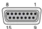
⑤ 15-pole D-Sub jack "IO"
1 alarm output: NO contact
2 alarm output: common contact
3 RS485 D+
4 RS485 D -
5 alarm input of channel 1
6 alarm input of channel 2
7 alarm input of channel 3
8 alarm input of channel 4
9 alarm output: NC contact
10 – 15 ground
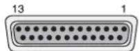
DMR-608 and DMR-616
⑥25-pole D-Sub jack "IO"
1 alarm output: NO contact
2 alarm output: common contact
3 RS485 D+
4 RS485 D -
5 not used
6 alarm input of channel 1
7 alarm input of channel 2
8 alarm input of channel 3
9 alarm input of channel 4
10 alarm input of channel 5
11 alarm input of channel 6
12 alarm input of channel 7
13 alarm input of channel 8
14 alarm output: NC contact
15–17 not used
18 alarm input of channel 9 (DMR-616 only)
19 alarm input of channel 10 (DMR-616 only)
20 alarm input of channel 11 (DMR-616 only)
21 alarm input of channel 12 (DMR-616 only)
22 alarm input of channel 13 (DMR-616 only)
23 alarm input of channel 14 (DMR-616 only)
24 alarm input of channel 15 (DMR-616 only)
25 alarm input of channel 16 (DMR-616 only)
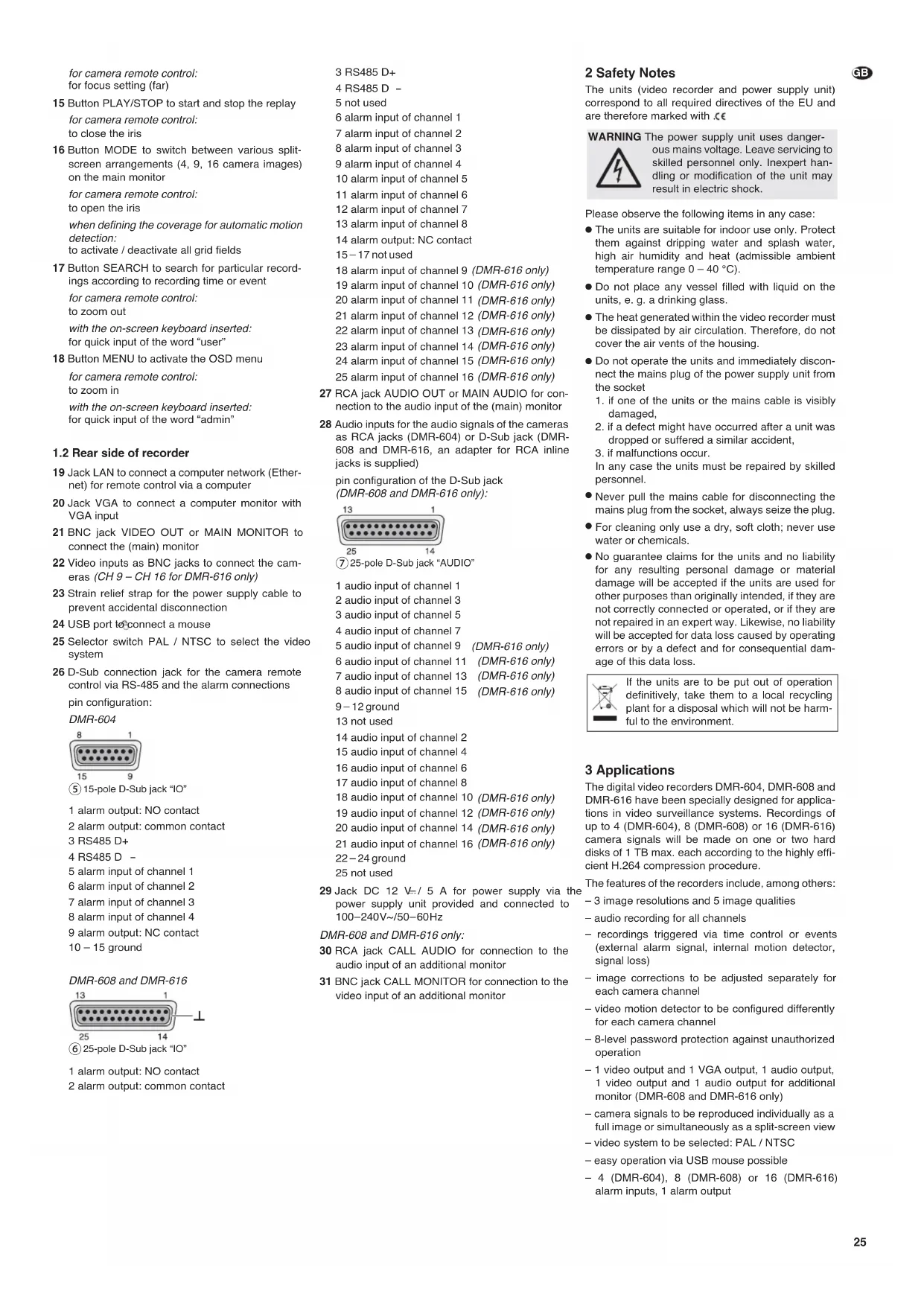
27 RCA jack AUDIO OUT or MAIN AUDIO for connection to the audio input of the (main) monitor
28 Audio inputs for the audio signals of the cameras as RCA jacks (DMR-604) or D-Sub jack (DMR-608 and DMR-616, an adapter for RCA inline jacks is supplied)
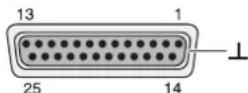
pin configuration of the D-Sub jack (DMR-608 and DMR-616 only):
25 14
⑦ 25-pole D-Sub jack "AUDIO"
1 audio input of channel 1
2 audio input of channel 3
3 audio input of channel 5
4 audio input of channel 7
5 audio input of channel 9 (DMR-616 only)
6 audio input of channel 11 (DMR-616 only)
7 audio input of channel 13 (DMR-616 only)
8 audio input of channel 15 (DMR-616 only)
9–12 ground
13 not used
14 audio input of channel 2
15 audio input of channel 4
16 audio input of channel 6
17 audio input of channel 8
18 audio input of channel 10 (DMR-616 only)
19 audio input of channel 12 (DMR-616 only)
20 audio input of channel 14 (DMR-616 only)
21 audio input of channel 16 (DMR-616 only)
22-24 ground
25 not used
29 Jack DC 12 V-/5 A for power supply via the power supply unit provided and connected to 100-240V\~/50-60Hz
DMR-608 and DMR-616 only:
30 RCA jack CALL AUDIO for connection to the audio input of an additional monitor
31 BNC jack CALL MONITOR for connection to the video input of an additional monitor
2 Safety Notes
The units (video recorder and power supply unit) correspond to all required directives of the EU and are therefore marked with .€
WARNING

The power supply unit uses dangerous mains voltage. Leave servicing to skilled personnel only. Inexpert handling or modification of the unit may result in electric shock.
Please observe the following items in any case:
- The units are suitable for indoor use only. Protect them against dripping water and splash water, high air humidity and heat (admissible ambient temperature range 0 – 40 °C).
- Do not place any vessel filled with liquid on the units, e. g. a drinking glass.
- The heat generated within the video recorder must be dissipated by air circulation. Therefore, do not cover the air vents of the housing.
- Do not operate the units and immediately disconnect the mains plug of the power supply unit from the socket
-
if one of the units or the mains cable is visibly damaged,
-
if a defect might have occurred after a unit was dropped or suffered a similar accident,
-
if malfunctions occur. In any case the units must be repaired by skilled personnel.
- Never pull the mains cable for disconnecting the mains plug from the socket, always seize the plug.
- For cleaning only use a dry, soft cloth; never use water or chemicals.
- No guarantee claims for the units and no liability for any resulting personal damage or material damage will be accepted if the units are used for other purposes than originally intended, if they are not correctly connected or operated, or if they are not repaired in an expert way. Likewise, no liability will be accepted for data loss caused by operating errors or by a defect and for consequential damage of this data loss.

If the units are to be put out of operation definitively, take them to a local recycling plant for a disposal which will not be harmful to the environment.
3 Applications
The digital video recorders DMR-604, DMR-608 and DMR-616 have been specially designed for applications in video surveillance systems. Recordings of up to 4 (DMR-604), 8 (DMR-608) or 16 (DMR-616) camera signals will be made on one or two hard disks of 1 TB max. each according to the highly efficient H.264 compression procedure.
The features of the recorders include, among others:
- 3 image resolutions and 5 image qualities
– audio recording for all channels
- recordings triggered via time control or events (external alarm signal, internal motion detector, signal loss)
– image corrections to be adjusted separately for each camera channel
– video motion detector to be configured differently for each camera channel
- 8-level password protection against unauthorized operation
- 1 video output and 1 VGA output, 1 audio output, 1 video output and 1 audio output for additional monitor (DMR-608 and DMR-616 only)
– camera signals to be reproduced individually as a full image or simultaneously as a split-screen view
– video system to be selected: PAL / NTSC
– easy operation via USB mouse possible
- 4 (DMR-604), 8 (DMR-608) or 16 (DMR-616) alarm inputs, 1 alarm output

– alarm triggering via motion detection, external alarm signal, video signal loss
– USB 2.0 interface for exporting video files
- RS-485 interface for remote control of suitable cameras (PTZ)
- LAN interface for connection to a computer network/tothe Internet
- remote access for live surveillance, replay of recordings and configuration of the recorder via LAN/Internetbycomputer
– recording, live surveillance and remote access possible at the same time
– program to replay exported recordings will be exported by the recorder
4 Installing a Hard Disk
To make video recordings, install a hard disk (connection type SATA, 1 TB max.) first. If necessary, install a second hard disk (also connection type SATA, 1 TB max.). To install the hard disk(s):
1) Disconnect the recorder from the power supply. Important: If the recorder is already operated with a hard disk, shut down the system of the recorder via the OSD menu ( chapter 17) before disconnecting the power supply.
2) Release the screws fixing the cover of the housing, then remove the cover.
3) Connect the plugs of the power supply cable (b) to the contacts of the hard disk(s) according to figure 4. Connect the data output of the first hard disk (I) via one of the data cables provided to the connection "SATA MASTER" on the PCB; connect the data output of the second hard disk (II) to the connection "DATA SLAVE".
4) Fasten the first hard disk (I) via two screws on the right to the housing. Fasten the second hard disk (II) via two screws on the left to the mounting brackets. Additionally use two screws each to fasten the two hard disks on the bottom plate.
5) Replace the cover of the housing and retighten the screws.
Notes
- If the file system of the hard disk inserted is not compatible to the file system of the recorder, the recorder will reformat the hard disk without warning. All data on this hard disk will be deleted!
- Before removing a hard disk already operated in the recorder, deactivate it via the OSD menu (Chapter 11.2).
5 Connecting Units
Figures 74 and 75 on the last pages of this instruction manual show an example for connection each for DMR-604 and DMR-616; however, it will not be necessary to use all of the connection possibilities shown. The connection possibilities of the DMR-608 only differ from those of the DMR-616 in the number of channels.
Before connecting any units or changing any existing connections (except for USB connections), shut down the system of the recorder via the OSD menu ( Chapter 17 ) and disconnect the recorder from the power supply.
5.1 Video connections
1) Connect the video outputs of the cameras to the jacks CH1-CH4 or CH1-CH8/16 (22).
2) Connect the video input of a monitor to the jack VIDEO OUT or MAIN MONITOR (21). To connect an additional monitor allowing to view individual cameras in full image display, independently of the main monitor, use the jack CALL MONITOR (31) provided on the recorders DMR-608 and DMR-616.
3) To connect a computer monitor with VGA input, use the jack VGA (20). The video signal corresponds to that at the output for the main monitor (21).
5.1.1 Selecting the video system
Set the recorder to the video system of the cameras used with the selector switch PAL/NTSC (25). When switching over during operation, the system must be restarted so that the change will become effective (Chapter 17).
5.2 Audio connections
1) For audio recordings and/or live surveillance, the RCA input jacks AUDIO IN CH1 – CH4 (28) allow to connect, for example, the audio outputs of cameras with integrated microphones or the preamplifiers of microphones set up separately. The recorders DMR-608 and DMR-616 each are supplied with an adapter with RCA inline jacks for connection to the 25-pole D-Sub jack AUDIO (28).
2) For audio reproduction, the audio signal of the channel currently displayed will be available at the RCA output jack AUDIO OUT (27) on the DMR-604. Correspondingly, on the DMR-608 and DMR-616, the audio signal will be available at the jack MAIN AUDIO (27) for the output MAIN MONITOR (21) and at the jack CALL AUDIO (30) the audio signal for the output CALL MONITOR (31). Define in the operating menu if live and replay sound, live sound only or no sound will be reproduced.
To reproduce the audio recording or the live sound via a monitor with integrated speaker or via an audio system, connect one of the outputs to the audio input of the monitor or to a line input of the audio system.
5.3 Alarm and control connections
Via the D-Sub jack IO (26), the recorder offers various inputs and outputs for control and alarm evaluation.
5.3.1 Alarm inputs
As alarm sensors, use e. g. motion detectors or light barriers equipped with NO (normally open) contacts or NC (normally closed) contacts. Connect the sensors to the following contacts of the D-Sub plug supplied:
DMR-604
sensor for channel 1 to contact 5 and ground sensor for channel 2 to contact 6 and ground sensor for channel 3 to contact 7 and ground sensor for channel 4 to contact 8 and ground ground = contacts 10 - 15
DMR-608 and DMR-616
sensor for channel 1 to contact 6 and ground sensor for channel 2 to contact 7 and ground sensor for channel 3 to contact 8 and ground sensor for channel 4 to contact 9 and ground sensor for channel 5 to contact 10 and ground sensor for channel 6 to contact 11 and ground sensor for channel 7 to contact 12 and ground sensor for channel 8 to contact 13 and ground
A contact pin for ground is not provided on the jack IO. For ground connection, use, for example, the body of the plug (shielding) or the GND contacts of the jack AUDIO (28).
DMR-616
sensor for channel 9 to contact 18 and ground sensor for channel 10 to contact 19 and ground sensor for channel 11 to contact 20 and ground sensor for channel 12 to contact 21 and ground sensor for channel 13 to contact 22 and ground sensor for channel 14 to contact 23 and ground sensor for channel 15 to contact 24 and ground sensor for channel 16 to contact 25 and ground Adjust the contact type (NO or NC) separately for each channel in the OSD menu of the recorder (chapter 10.1).
5.3.2 Alarm output
As a floating alarm output, a relay with normally open (NO) and normally closed (NC) contact (with a maximum load of 24 V/500 mA) is available. The alarm output allows to connect, for example, an audible or visible alarm device.
NO contact = contact 1
NC contact = contact 9 (DMR-604)
contact 14 (DMR-608 and
DMR-616)
common contact = contact 2
5.3.3 Camera remote control (DOME)
Via the RS-485 interface, remote control of suitable cameras will be possible. According to the features of the camera, movements such as pan and tilt, but also zoom, iris and automatic iris / autofocus will be controlled via the recorder.
Connect the plug contacts 3 (D+) and 4 (D-) to the corresponding contacts of the camera. It will be possible to connect another camera in parallel to the connections of the first one and a further camera to this one again, etc. until all cameras have been connected. To reduce interference, it is recommended to use twisted cables.
On the last camera, terminate the data bus by connecting the two cables via a 120 Ω resistor (this will often be possible via a switch on the camera).
Assign an individual address to the cameras so that the recorder will be able to address them separately. This is usually made via an OSD menu or DIP switches on the camera. Make the corresponding settings on the recorder, i.e. the address to control the corresponding camera and the transmission parameters and protocol required (Chapter 12.1).
5.4 Mouse
For a more convenient operation of the recorder, connect a USB mouse with PS/2 protocol to USB port ∅(24) or ↓(9). This will also be possible during operation.
5.5 Computer network (LAN)
For remote control of the recorder via a computer, connect the two units via the RJ45 jack LAN (19) or link the recorder to a local computer network (e.g. via a router) or make a connection to the Internet.
Note: For direct connection to a computer, a crossover cable will be required.
5.6 Mains connection
Finally connect the power supply unit provided to the jack 12 V\~/5 A (29) and connect the mains plug to a socket (100 - 240 V\~/47 - 63 Hz).
To prevent accidental disconnection, clamp the cable leading to the recorder to the strain relief strap (23).
As a sudden power failure during operation may result in data loss and cause damage to the recorder, it is highly recommended to use an uninterruptible power supply (UPS).
5.7 USB storage medium
For external backup of the recordings or for transmission to a computer, it will be possible to connect, for example, a USB flash drive (flash EEPROM memory) to the USB port ♂(9). For recognizing this external storage medium, it must be connected while the recorder is operated.
6 Operation
When the supply voltage has been applied, the recorder will be switched on. The power indication ♀ (2) will light up. The recorder will start a self-test. First, a test pattern and the results of the self-test will appear on the screen, then a split screen will be displayed showing all camera images selected for live surveillance (Chapter 6.2.6).
To end the operation, shut down the system of the recorder via the operating menu first ( F_55 chapter 17) before disconnecting the recorder from its supply voltage; otherwise data loss or damage to the recorder may result.
6.1 Activating the OSD menu
The settings of the recorder are made via OSD menu. For this purpose, use the buttons on the recorder or a computer mouse. Various menu languages will be available (Selection of menu language i: chapter 6.2.1). This instruction manual only refers to the English menus preset in the factory.
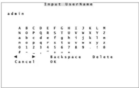
To activate the menu, press the button MENU (18). If the password protection has been activated, a request will appear to enter a valid user name (fig. 8).
text_image
Input Username admin A B C D E F G H I J K L M N O P Q R S T U V W X Y Z a b c d e f g h i j k l m n o p q r s t u v w x y z 0 1 2 3 4 5 6 7 8 9 . ! @- _ , " + = *
◀ ▶ Backspace Delete Cancel OK⑧ Input window for user name
To enter a character, select it with the buttons ▲, ◀
▶ and (8) and confirm with the button ENTER (6).
To enter numbers directly, use the camera channel buttons 1 - 10/0 (1); to enter a full stop “.” directly use the button CALL (10).
Move the cursor in the word via the icons and ▶. To correct it, use Delete to delete the character near the cursor; use Backspace or press the button DOME (12) to delete the character on the left of the cursor.
Two possible user names are factory-set: "admin" with full access permission and "user" with limited access permission (Chapter 13). To enter "admin" quickly, press the button MENU (18); to enter "user", press the button SEARCH (17).
When the name is complete, store it with OK or exit the input with Cancel.
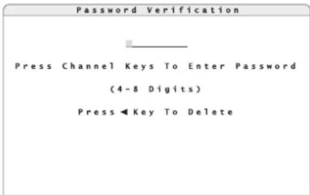
After the user name has been entered, the window for entering the password will appear (fig. 9).
text_image
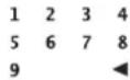
Password Verification Press Channel Keys To Enter Password (4-8 Digits) Press◀Key To Delete⑨ Password input window
Enter the corresponding password via the buttons 1 - 10/0 (1). To delete an incorrect number, use the button (8).
The preset password for "admin" is "1234"; for "user" it is "4321".
Terminate the input with the button ENTER (6).
Note: To prevent unauthorized access, it is highly recommended to change the preset passwords (chapter 13).
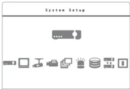
After the correct combination of user name and password has been entered, the main menu (fig. 10) will appear. In case of an input error, the message "You do not have proper authority to access this function" will appear.
To deactivate this message, press any button.
text_image
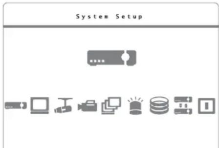
System Setup⑩ Main menu
Select the desired submenu with the button (8) and activate it with the button ENTER (6). If not all submenus are available, the access permission level for the user name entered is too low (chapter 13.1).
Select the desired line in the submenus with the buttons and (8). To change a setting, press the button ENTER in the marked line first. The current setting will flash; use the buttons and to change it. To store the changed setting, press the button ENTER. To exit an input field without changing the setting, press the button ESC (7).
If "Execute" is shown on the right of a line, the corresponding action will be executed when the button ENTER is pressed. For some menu lines, another submenu will be activated each time the button ENTER is pressed.
To exit a submenu and to exit the operating menu, press the button ESC. The menu will automatically disappear approx. 90 seconds after the last operation.
If the password protection has been activated, the access permission level (1 - 8) will be displayed in the upper right corner of the screen. After exiting the menu, the user is still logged in and will be able to reactivate the menu or other functions without having to enter the user name and the password again. If the button ESC is pressed once again or if no menu function has been activated for more than 5 minutes, the user will be logged out. Instead of the access permission level, "N" will appear.
6.1.1 Menu control with the mouse
If a USB mouse with wheel has been connected (chapter 5.4), use it to make the menu settings.
1) Press the right mouse button. The following window will appear:
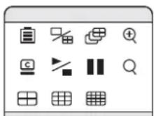
⑪ Mouse palette
2) Click the icon Menu with the left mouse button. If the password protection has been activated, a request to enter a valid user name will appear (fig. 8). Enter the user name as described in chapter 6.1, however, it will be possible to click the characters to be entered directly with the mouse. For entering the password subsequently, a number palette (fig. 12) will additionally appear when a mouse has been connected.

⑫ Input of numbers with the mouse
Click the numbers or click to delete the last input. To terminate the input, click next to the palette with the left mouse button.
After the correct combination of user name and password has been entered, the main menu (fig. 10) will appear. In case of an input error, the message "You do not have proper authority to access this function" will appear. To deactivate this message, press a mouse button.
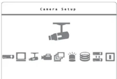
3) Click the corresponding icon in the main menu to activate the desired submenu. The name of the submenu will be displayed at the top once the mouse pointer is moved over the icon.
4) Click the desired line in the submenu to change a setting, to activate another submenu or to execute an action.
5) Use the mouse wheel to change a setting and click the left mouse button to store the input.
6) To exit an input field without changing the setting, press the right mouse button.
7) To exit a submenu and to deactivate the operating menu, press the right mouse button.
6.1.2 Menu overview
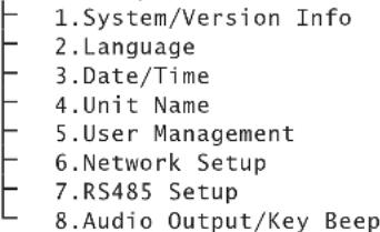
An overview of the menu structure with the most important submenus can be found in figure 13.
An overview of the menus:
System/Version Info
Indication of recorder type, video system, recorder version, firmware version and MAC address
Language
Selection of menu language
Date/Time
Setting of date and time, indication format, time zone, automatic change to daylight saving time, time synchronization via network
Unit Name
Input of a recorder name
User Management
Definition of the access permission levels for the operating functions and of the access permission for users, definition and activation of the password protection
Network Setup
Parameters for network connection
RS485 Setup
Settings of RS-485 transmission parameters for the cameras to be controlled via data bus
Audio Output/Key Beep
Settings for audio output and activation / deactivation of key beep
Monitor Setup
Activation/deactivation of camera titles, image centring, resolution for the VGA output, test pattern (colour bars)
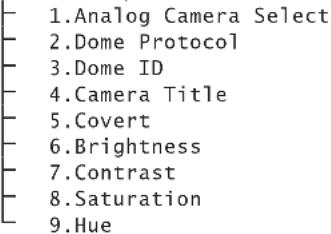
Camera Setup
Settings for camera inputs: remote control protocol, camera title, visibility, image corrections (brightness, contrast, saturation, hue)
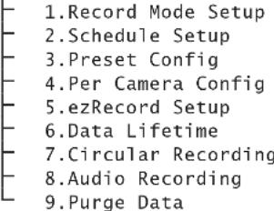
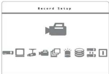
Record Setup
Recording presets (resolution, quality, recording schedule, storage time, overwrite mode, audio recording), deletion of recordings
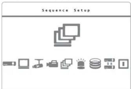
Sequence Setup
Settings for sequence function (order of cameras and dwell time) on the main monitor and additional monitor
Event Setup
Settings for evaluating events such as signal loss, automatic motion detection via camera images, signals at the alarm inputs

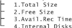
Database Setup
Indication of information concerning the internal hard disks and activation, deactivation and formatting of the hard disks
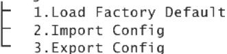
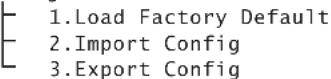
Configuration
Export or import of all settings of the recorder, reset to factory settings
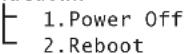
Shutdown
Shutdown of the system (to switch off) or restart of the system
MENU
System Setup
text_image
1.System/Version Info 2.Language 3.Date/Time 4.Unit Name 5.User Management 6.Network Setup 7.RS485 Setup 8.Audio Output/Key BeepMonitor Setup

Camera Setup
text_image
1.Analog Camera Select 2.Dome Protocol 3.Dome ID 4 turner Title 5.Covert 6.Brightness 7.Contrast 8.Saturation 9.HueRecord Setup
text_image
1.Record Mode Setup 2.Schedule Setup 3.Preset Config 4.Per Camera Config 5.ezRecord Setup 6.Data Lifetime 7.Circlear Recording 8.Audio Recording 9.Purge DataSequence Setup
Event Setup
text_image
1. Internal Buzzer 2. Event Icon 3. Email Notice 4. Email Attachment 5. Event Full Screen 6. Event Duration 7. Per Channel ConfigDatabase Setup
Configuration
Shutdown

⑬ Menu structure
6.2 Basic settings
6.2.1 Changing the menu language
The preset language for the settings and dialogues in the OSD menu is English. This instruction manual refers to this language. To change the language:
1) As described in chapter 6.1, activate the main menu (fig. 14) and then the submenu System Setup (fig. 15).
text_image
System Setup⑭ Main menu: "System Setup" selected
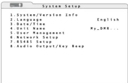
text_image
1. System/Version Info 2. Language English 3. Date/Time 4. Unit Name My_DMR... 5. User Management 6. Network Setup 7. RS4&5 Setup 8. Audio Output/Key Beep⑮ Submenu "System Setup"
2) Select the desired menu language in the line 2.Language.
6.2.2 Key beep and audio output
To deactivate the beep whenever a button is pressed:
1) Via the main menu (fig. 14), activate the submenu System Setup (fig. 15).
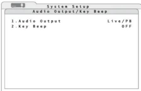
2) Via the line 8. Audio Output/Key Beep, activate the corresponding submenu (fig. 16).
text_image
System Setup Audio Output/Key Beep 1. Audio Output Live/PB 2. Key Beep OFF⑯ Submenu "Audio Output / Key Beep"
3) In the line 2. Key Beep, define if a beep will sound whenever a button is pressed (ON) or not (OFF).
To define the audio signal at the audio output AUDIO OUT or MAIN AUDIO (27):
4) In the line 1. Audio Output, select live sound only (Always Live), change-over to the sound of the recording while replaying (Live/PB) or no sound (OFF).
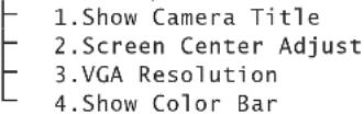
6.2.3 Monitor settings
To set the main monitor:
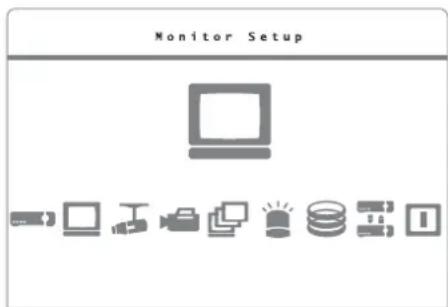
1) Via the main menu (fig. 17), activate the submenu Monitor Setup (fig. 18).
text_image
Monitor Setup⑰ Main menu: "Monitor Setup" selected
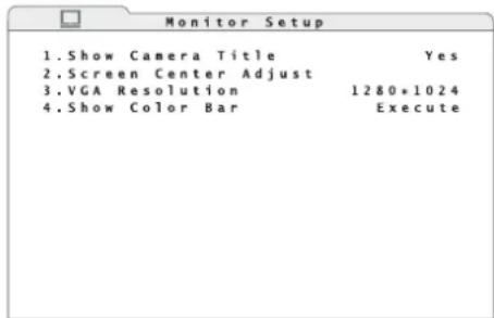
text_image
Monitor Setup 1.Show Camera Title Yes 2.Screen Center Adjust 3.VGA Resolution 1280*1024 4.Show Color Bar Execute⑱ Submenu "Monitor Setup"
2) In the line 3.VGA Resolution, select the desired resolution for the VGA output (pixels horizontal × vertical).
Note: If you select a higher resolution than the monitor will be able to display, "No Signal" will appear on the screen. In this case, press the button ESC (7) to keep the previous setting.
3) To centre the image on the monitor, use the function 2. Screen Center Adjust. Move the image with the buttons ,▲, ◀ and ▶ (8) in▼ such a way that it will be displayed in the centre of the monitor.
If a mouse has been connected, click the cross inserted in the centre to move the image. Move the mouse to position the image in the centre. To store this setting, press the left mouse button.
4) To set the colours of a monitor, insert a test pattern of vertical colour bars via the function 4.Show Color Bar. To return to the menu, press the button ENTER (6) or ESC (7) or a mouse button.
5) In the line 1. Show Camera Title, it will also be possible to define if the camera titles will be displayed on the monitor (Yes) or not (No) [Chapter 6.2.4]
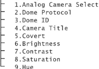
6.2.4 Camera titles
For each camera channel, it will be possible to insert a title of up to 11 characters in the image. To assign titles to the cameras:
1) Via the main menu (fig. 19), activate the submenu Camera Setup (fig. 20).
text_image
Camera Setup⑲ Main menu: "Camera Setup" selected
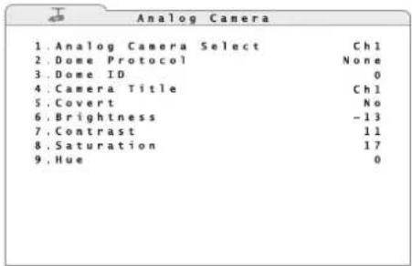
text_image
Analog Camera 1. Analog Camera Select Ctrl 2. Dome Protocol None 3. Dome ID 0 4. Camera Title Ctrl 5. Covert No 6. Brightness -13 7. Contrast 11 8. Saturation 17 9. Hue 0⑳ Submenu "Camera Setup /Analog Camera"
2) In the line 1. Analog Camera Select, select the channel for the camera to be titled. The current camera title will be displayed on the right of the line 4. Camera Title.
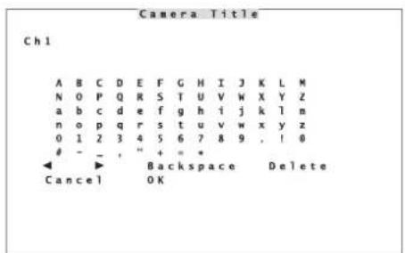
3) To change the title, activate the input window for characters (fig. 21) via the line 4. Camera Title.
text_image
Camera Title Ch1 A B C D E F G H I J K L M N 0 P Q R S T U V W X Y Z a b c d e f g h i j k l m n o p q r s t u v w x y z 0 1 2 3 4 5 6 7 8 9 , ! 0- - " + = *
◀ ▶ Backspace Delete Cancel OK②1 Input window "Camera Title"
4) To enter a character, select it with the buttons ▲ ◀, ◀und (8) and confirm with the button ENTER (6). Alternatively, click the character with the mouse. To enter numbers directly, use the camera channel buttons 1 - 10/0 (1); to enter a full stop “.” directly, use the button CALL (10).
Via the icons and , move the cursor in the word. To correct it, use Delete to delete the character near the cursor; use Backspace or press the button DOME (12) to delete the character on the left of the cursor.
5) After entering, store the title with OK or exit the input window with Cancel without changing the title.
It depends on the setting 1. Show Camera Title in the submenu Monitor Setup ( chapter 6.2.3) whether or not the camera titles will be displayed on the monitor.
6.2.5 Correcting image properties
If necessary, correct the properties of the camera images.
1) Via the man menu (fig. 19), activate the submenu Camera Setup (fig. 20).
2) In the line 1. Analog Camera Select, select the channel for the camera image to be corrected.
3) The following image properties may be corrected:
6. Brightness
-
Contrast
-
Saturation
-
Hue
Note: To view the changes, select the option No in the line 5. Covert.
6.2.6 Visibility of camera images
For recording the signals of a camera without displaying them on the main monitor in the normal mode, set the corresponding channel to "covert".
1) Via the main menu (fig. 19), activate the submenu Camera Setup (fig. 20).
2) In the line 5. Covert, define if the camera image will be covert (Yes) or if it will be visible on the monitor during live surveillance and during replay of recordings (No).
Note: This setting will not affect the display of a camera signal on an additional monitor connected to the output CALL MONITOR (31).
6.2.7 Date and time
The recorder is equipped with a clock. Due to a battery, this clock will keep running when the recorder is switched off or in case of power failure. To set the date and time:
1) Via the main menu (fig. 14), activate the submenu System Setup (fig. 15).
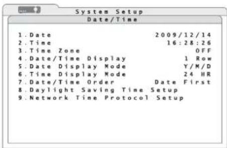
2) Via the line 3. Date/Time, activate the sub-menu Date/Time (fig. 22).
text_image
System Setup Date/Time 1. Date 2009/12/14 2. Time 16:28:26 3. Time Zone OFF 4. Date/Time Display 1 Row 5. Date Display Mode Y/M/D 6. Time Display Mode 24 HR 7. Date/Time Order Date First 8. Daylight Saving Time Setup 9. Network Time Protocol Setup② Submenu "Date/Time"
3) In the line 5. Date Display Mode, select the date format to be displayed:
D/M/Y
M/D/Y
Y/M/D
Note: A change of date and time will affect future recordings only. The time indications of existing recordings will not be changed. To prevent any resulting data inconsistency, it is recommended to format the hard disk(s) after changing the date or the time (chapter 11.2).
After changing the settings described below, a warning will appear on the screen pointing out this problem. To confirm the change, press the button ENTER (6) or the left mouse button; to cancel the change, press the button ESC (7) or the right mouse button.
4) In the line 1. Date, enter the current date in the format selected.
5) In the line 6. Time Display Mode, define if the time will be indicated in 12-hour format (12 HR) or 24-hour format (24 HR).
6) Enter the current time accordingly in the line 2.Time.
7) In the line 7. Date/Time Order, define if the date will be indicated before the time (Date First) or if the time will be indicated before the date (Time First).
8) In the line 4. Date/Time Display, define if the date and the time will be indicated in two lines (2 Rows), in one line (1 Row) or not at all (OFF).
9) In the line 3. Time Zone, select the time zone for the place of application (e.g. 00:00 for UK).
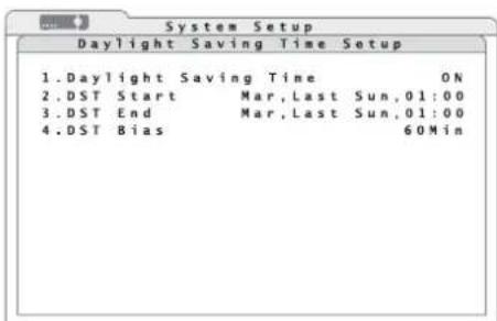
10) For automatic change between daylight saving time and standard time, activate the corresponding submenu (fig. 23) via the line 8. Daylight Saving Time Setup.
text_image
System Setup Daylight Saving Time Setup 1.Daylight Saving Time ON 2.DST Start Mar,Last Sun,01:00 3.DST End Mar,Last Sun,01:00 4.DST Bias 60Min②3 Submenu "Daylight Saving Time Setup"
11) In the line 1. Daylight Saving Time, activate (ON) or deactivate (OFF) the automatic
change between daylight saving time and standard time. With automatic change, an "S" (summer time) for daylight saving time or a "W" (winter time) for standard time will appear in front of the time indication.
12) In the line 2. DST Start, define the time for changing from standard time to daylight saving time (e.g. Mar, Last Sun, 02:00 for always switching over on the last Sunday in March at 2 a.m.).
In the line 3. DST End, define the time for changing from daylight saving time to standard time (e.g. Oct, Last Sun, 03:00 for always switching back on the last Sunday in October at 3 a. m.).
In the line 3. DST Bias, define the time difference (60 minutes in most countries).
13) For automatic synchronization of time via a computer network / via the Internet, it is recommended to set up the network connection first ( Chapter 16.1).
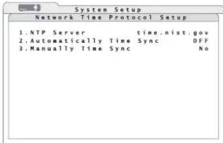
Via the line 9. Network Time Protocol Setup, activate the corresponding submenu (fig. 24). This menu item will not be available until the time zone has been defined (step 9).
text_image
Network Time Protocol Setup 1.NTP Server time.nist.gov 2.Automatically Time Sync OFF 3.Manually Time Sync No⑳ Submenu "Network Time Protocol Setup"
14) Enter the network / Internet address (URL) of the desired NTP server via the line 1. NTP Server or keep the preset server. Enter it as described for the camera title (chapter 6.2.4).
Further examples for IP addresses of NTP servers:
129.6.15.28, 129.6.15.29, 132.163.4.101
132.163.4.102, 132.163.4.103, 128.138.140.44
192.43.244.18, 131.107.1.10, 69.25.96.13
206.246.118.250, 208.184.49.9, 64.125.78.85
207.200.81.113, 64.236.96.53, 68.216.79.113
15) In the line 2. Automatically Time Sync, define if the clock of the recorder will be automatically synchronized every hour via the network (ON) or not (OFF).
16) To synchronize the clock of the recorder immediately via the network, enter "Yes" in the line 3. Manually Time Sync. The recorder will try to make a connection to the NTP server immediately. The message "Time syncing/please stand by" will appear.
If the message "Fail to time sync/Press any key to return" appears, the synchronization has failed. In this case, check the network connection and the network settings (Chapter 16.1). To return to the menu, press any button.
If the clock does not keep the time until the recorder is switched on again, the battery (button cell inside the recorder) may be exhausted and must be replaced.
6.2.8 Unit name
When operating several recorders at the same time, it will be possible to assign an individual name to each recorder (to distinguish them for remote access via a computer network).
1) Via the main menu (fig. 14), activate the submenu System Setup (fig. 15).
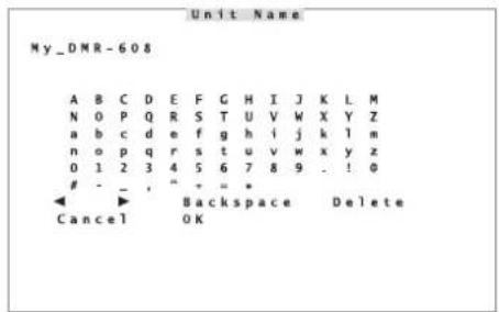
2) The name "DVR" is preset. To change the name, activate the window Unit Name (fig. 25) via the line 4.Unit Name.
text_image
Unit Name My_DMR-608 A B C D E F G H I J K L M N O P Q R S T U V W X Y Z a b c d e f g h i j k l m n o p q r s t u v w x y z 0 1 2 3 4 5 6 7 8 9 . ! 0- _ , " + = *
◀ ▶ Backspace Delete Cancel OK⑲ Input window "Unit Name"
3) Change the name of the recorder as described for the camera titles in chapter 6.2.4.
7 Live Surveillance
The display of the camera images for live surveillance is independent of the recording activity of the recorder.
To switch between full image display of a camera and simultaneous display of several camera images on the main monitor, press the button MODE (16). It depends on the number of inputs on the corresponding version which of the split-screen arrangements (2 × 2, 3 × 3, 4 × 4) will be available.
To display a camera image as a full image, press the corresponding camera channel button (1). To return to the split-screen view, press the button MODE.
To "freeze" the display (still image), press the button FREEZE (14). In the lower left corner, Freeze will be inserted. To return to the live images, press the button once again.
To zoom in an image section by the factor 2 in the full image display, press the button ENTER (6). In the lower left corner, X2 Zoom will be inserted. To move the section, use the arrow buttons (8). To return to normal-size display, press the button ENTER once again.
If a mouse has been connected, click an image on the split-screen view with the left mouse button to display this camera channel as a full image. To return to a split-screen view, click the image once again. Alternatively, activate the mouse palette (fig. 11) with the right mouse button and click the icon "Mode" with the left mouse button or directly select the desired split-screen arrangement 12 × 2 ; "33 3" or "4 × 4". To freeze the display, click Freeze"; to zoom it in, click Zoom". To move the section zoomed in, click the directional arrows inserted. Click the left mouse button to freeze the image zoomed in; click the right mouse button to return to the live image. Click the right mouse button again to return to normal-size display.
7.1 Configuring the sequence function
With the sequence function, the view will change automatically during live surveillance. To configure the sequence function:
1) Via the main menu (fig. 26), activate the submenu Sequence Setup (fig. 27).
text_image
Sequence Setup⑳ Main menu: "Sequence Setup" selected
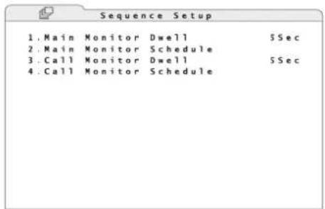
text_image
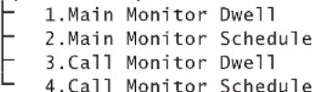
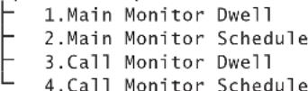
1.Main Monitor Dwell SSec 2.Main Monitor Schedule 3.Call Monitor Dwell SSec 4.Call Monitor Schedule⑳ Submenu "Sequence Setup"
2) In the line 1. Main Monitor Dwell, define the dwell time for each camera channel.
3) Activate the corresponding submenu (fig. 28) via the line 2.Main Monitor Schedule.
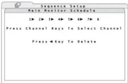
text_image
Sequence Setup Main Monitor Schedule 1▶ 2▶ 3▶ 4▶ 5▶ 6▶ 7▶ 8 Press Channel Keys To Select Channel Press Key To Delete⑳ Submenu "Main Monitor Schedule"
4) To change the sequence of the camera channels displayed, delete the preset channels with the button (6) and enter the desired cameras with the channel buttons (1). Do not use a channel more than once in the sequence. To store the changes, exit the submenu with the button ENTER (6) or press the button ESC (7) to cancel the changes.
For operation with a mouse, icons will be inserted in the lower part of the window; click them for input. To store the changes and to exit the submenu, click the left mouse button at any other place; to cancel the changes, click the right mouse button.
5) For an additional monitor (DMR-608 / DMR-616 only), make the settings performed in steps 2) to 4) in the same way via the lines 3. Call Monitor Dwell and 4. Call Monitor Schedule.
7.2 Activating the sequence function
To activate the sequence function, press the button SEQ (13). The automatic change of camera channels will start and Sequence Mode will be inserted in the lower left corner.
Note: If the zoom has been activated (insertion X2 Zoom) or the display has been frozen (insertion Freeze), deactivate these functions first.
To deactivate the sequence function, press the button SEQ or the button ESC (7).
To start the sequence function with a mouse, activate the mouse palette (fig. 11) with the right mouse button and click the icon "Sequence". To deactivate the sequence function, click the right mouse button.
7.3 Additional monitor
(DMR-608/DMR-616only)
An additional monitor connected to the output CALL MONITOR (31) is used to display live images of a camera as a full image while a multiple camera display or the replay of a recording is shown on the main monitor. It will not be possible to replay a recording on the additional monitor.
To select the camera channel to be displayed:
1) Press the button CALL (10). In the lower left corner of the main monitor, Call Mode will be inserted.
When using a mouse, activate the mouse palette (fig. 11) with the right mouse button and then click the icon "Search" with the left mouse button.
2) Switch the desired camera channel to the additional monitor with the channel buttons (1) or start the sequence function for the additional monitor with the button SEQ (13) [Configuring the sequence function chapter 7.1]. To stop the sequence, also press the button SEQ.
For operation with a mouse, icons will be inserted in the lower part of the window; click them for input.
3) To exit the Call mode, press the button CALL or the button ESC (7); when using a mouse, click the right mouse button.
8 Recording
The video signals will be recorded on the internal hard disks. These hard disks must be formatted before making the first recordings with the video recorder. To save storage space, the video signals will be compressed according to the highly efficient standard H.264 (MPEG-4 /AVC). The image quality of the recording (and thus the compression rate) will be adjustable.
It will be possible to record the camera signals permanently, according to a schedule or depending on events (automatic motion detection or signal at one of the alarm inputs). The recording status will be inserted in the lower left corner of the image displayed on the main monitor:
REC = permanent or time-controlled recording
EVENT ONLY = recording in case of events only Additionally, the indication REC (5) on the recorder will flash to indicate recording.
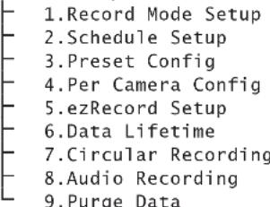
8.1 Settings for recording
1) Via the main menu (fig. 29), activate the submenu Record Setup (fig. 30).
text_image
Record Setup 1⑲ Main menu: "Record Setup" selected
text_image
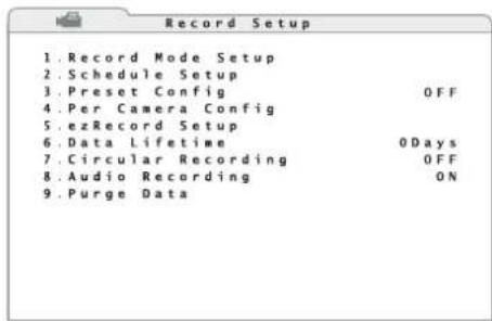
Record Setup 1. Record Mode Setup 2. Schedule Setup 3. Preset Config OFF 4. Per Camera Config 5. ezRecord Setup 6. Data Lifetime 0Days 7. Circular Recording OFF 8. Audio Recording ON 9. Purge Data③0 Submenu "Record Setup"
2) To facilitate the settings, presets for various requirements will be available via the line 3.Preset Config:
The presets 512/256/128Kbps DSL offer permanent recording of all camera channels at a constant data rate and corresponding memory requirements for each image with a fixed resolution:
| PAL | 720 × 288, 50 PPS |
| NTSC | 720 × 240, 60 PPS |
| 512Kbps DSL | 4KB/image |
| 256Kbps DSL | 3KB/image |
| 128Kbps DSL | 2KB/image |
For the presets Best Quality, Standard and Extended Record, the resolution will also be selectable:
| PAL | 720 × 576, 25 PPS | 720 × 288, 50 PPS | 360 × 288, 100 PPS |
| NTSC | 720 × 480, 30 PPS | 720 × 240, 60 PPS | 360 × 240, 120 PPS |
| Best Quality | 22 KB/ image | 12 KB/ image | 6 KB/ image |
| Standard | 14 KB/ image | 8 KB/ image | 4 KB/ image |
| Extended Record | 6 KB/ image | 4 KB/ image | 2 KB/ image |
To select the resolution, activate the corresponding submenu (fig. 31) via the line 1. Record Mode Setup.
text_image
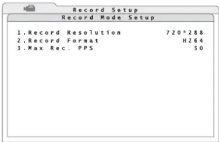
Record Setup Record Mode Setup 1. Record Resolution 720*288 2. Record Format H264 3. Max Rec. PPS 50③1 Submenu "Record Mode Setup"
Define the desired resolution (pixels horizontal × vertical) in the line 1. Record Resolution.
In the line 3. Max Rec. PPS define a maximum picture rate (PPS = pictures per second) depending on the resolution. (For DMR-604, the maximum picture rate will be defined by the resolution selected.)
Note: If a change has been made in the submenu Record Mode Setup, a message requiring a system restart will appear when exiting the submenu.
For the presets mentioned above, the total picture rate will principally be divided among all input channels, regardless of whether or not there is a camera signal at an input. For the preset ezRecord, however, the memory will be used more effectively: Only the channels with a camera signal applied will be recorded. To configure this preset chapter 8.1.1.
For recording in case of alarm triggering only (by motion detection or via an alarm input), select the preset Event Only. Define the type of events and their evaluation under Alarm Functions (Chapter 10).
If no preset has been selected (OFF), it will be possible to set each camera channel individually for recording via the line 4. Per Camera Config now accessible ( chapter 8.1.2).
3) In the line 6. Data Lifetime, define the number of days for which a recording will be available for replay. If no limit is desired for the replay time, set the value to 0Days.
Note: This setting will not affect the actual existence of a recording; it will limit the replay time intentionally. For replaying a recording made earlier, increase the value accordingly.
4) In the line 7. Circular Recording, define if the oldest data on the hard disk will be automatically overwritten (ON) and thus permanent recording will be possible. If the overwrite mode has been deactivated (OFF), the recording will stop once the hard disk(s) is (are) full and a signal will sound.
5) In the line 8. Audio Recording, define if audio signals will also be recorded (ON) or not (OFF).
8.1.1 Configuring "ezRecord"
The preset "ezRecord" allows a simple and effective setting for recording. To configure this preset:
1) Via the line 5.ezRecord Setup, activate the corresponding submenu (fig. 32).
text_image
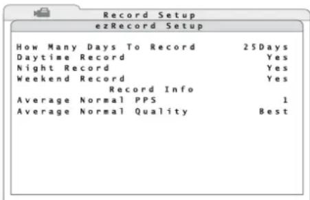
Record Setup ezRecord Setup How Many Days To Record 25Days Daytime Record Yes Night Record Yes Weekend Record Yes Record Info Average Normal PPS 1 Average Normal Quality Best③2 Submenu "ezRecord Setup"
2) In the line How Many Days To Record, define the minimum number of days for recording.
3) In the lines Daytime Record, Night Record and Weekend Record, define if normal recordings (i. e. without alarm triggering) will be made during these periods (Yes) or not (No). The periods will be defined in the recording schedule (chapter 8.1.3). If the option "Weekend Schedule" has been deactivated in the recording schedule, it will not be possible to set the line Weekend Record.
Depending on the capacity of the hard disk(s) installed and the preset values, the change of the other values will be calculated and displayed immediately when entering data, e. g. the average picture rate to be achieved with the presets will be displayed in the line Average Normal PPS and the corresponding quality will be displayed in the line Average Normal Quality.
Likewise, the possible recording time will be calculated immediately when the picture rate or the quality is changed.
Note: Only channels with a camera signal applied will be recorded. Calculations in this submenu will be based on the cameras currently connected. It is therefore recommended to repeat the setting in this submenu when the number of cameras connected is changed.
8.1.2 Configuring individual camera channels
If none of the presets for recording is the optimum solution for the application, it will be possible to configure the camera channels individually for recording. For this purpose, select the option OFF in the line 3.Preset Config.
1) Via the line 4. Per Camera Config, activate the corresponding submenu (fig. 33).
| Record Setup | ||||
| Per Camera Config | ||||
| Camera Select | CH1 | |||
| Day | Night | Weekend | ||
| Normal | PPS | 25 | 6.25 | 6.25 |
| Normal | Qlty | Best | Best | Best |
| Event | Max PPS | 25 | 25 | 25 |
| Event | Qlty | Best | Best | Best |
| Event | Act | Both | Both | Both |
③3 Submenu "Per Camera Config"
2) In the line Camera Select, select the channel of the camera to be adjusted.
3) In the line Normal PPS, define the picture rates (pictures per second) for the normal recording mode. The columns Day, Night and Weekend refer to the periods defined in the recording schedule (Chapter 8.1.3). If the option "Weekend Schedule" has been deactivated in the recording schedule, the values in this column will be insignificant. Set the picture rate to 0 if a camera signal is not to be recorded in the normal mode (only in case of alarm).
In the line Normal Qlty, select the quality of the video signal in the normal mode. With increased quality (Low → Fair → Mid → High → Best), the required memory space will also increase.
4) In the line Event Max PPS, define the maximum picture rates for the recording mode in case of alarm. The actual picture rate for recording a channel will depend on the number of channels recorded simultaneously in case of alarm.
In the line Event Q1ty, select the quality for recording the video signal in case of alarm. With increased quality (Low → Fair → Mid → High → Best), the required memory space will also increase.
5) In the line Event Act, define the type of event triggering an alarm recording.
Motion motion detection
Alarm signal at an alarm input
Both motion detection or signal at an alarm input
None no alarm recording
The type of event triggering an alarm recording also depends on the settings in the submenu "Event Setup" (Chapter 10).
Note: The total amount of picture rates for all channels may be the total picture rate as a maximum, i. e. before increasing the picture rate of a channel in normal mode, it may be necessary to decrease the picture rate of another channel. In case of alarm, the channel with the event triggering the alarm will take priority. The remaining picture rate will be divided among the channels recording normally.
8.1.3 Defining the recording schedule
For the recording preset "ezRecord" and for the individual recording configuration of the camera channels it will be necessary to define the recording times.
1) Via the line 2. Schedule Setup, activate the corresponding submenu (fig. 34).
text_image
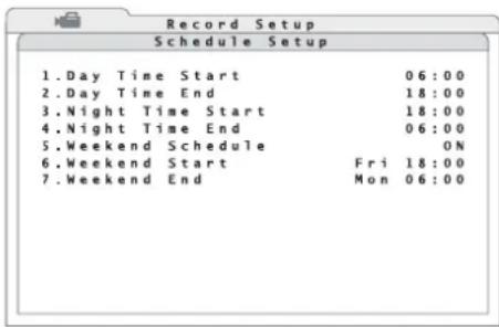
Record Setup Schedule Setup 1.Day Time Start 06:00 2.Day Time End 18:00 3.Night Time Start 18:00 4.Night Time End 06:00 5.Weekend Schedule ON 6.Weekend Start Fri 18:00 7.Weekend End Mon 06:00③4 Submenu "Schedule Setup"
2) In the line 1. Day Time Start, define the start of the recording period "day".
3) In the line 2. Day Time End, define the end of the recording period "day".
4) In the line 3. Night Time Start, define the start of the recording period "night".
5) In the line 4. Night Time End, define the end of the recording period "night".
6) In the line 5. Weekend Schedule, define if the recorder will distinguish between weekdays and weekend (ON) or not (OFF).
If ON has been selected, define the start of the weekend period in the line 6. Weekend Start and the end of the weekend period in the line 7. Weekend End.
Note: While recording, it will not yet be possible to replay a part of the latest recording as the data will still be in the buffer.

GB 9 Replay
1) To start the replay of a recording, press the button PLAY/ STOP (15). The replay will start where it ended the last time. When the button is pressed for the first time, the replay will start at the beginning of the recording. When searching for a specific recording, use the search function (Chapter 9.1).
The insertion “▶1” in the lower left corner of the image means that a recording is replayed forwards at single speed.
2) To modify the direction and the speed of the replay from "32" (32-fold speed, backwards) to "32" (32-fold speed, forwards), use the buttons and (8) At the end of the recording, END OF VIDEO will be inserted.
Note: While recording, it will not yet be possible to replay a part of the latest recording as the data will still be in the buffer.
3) The selection of the view is largely the same for the replay as for the live surveillance. The button MODE (16) is used to switch between the full image display of the recording of a camera channel and the simultaneous display of several channels on the main monitor. It depends on the number of inputs on the corresponding version which of the split-screen arrangements (2 × 2, 3 × 4 × 4) will be available.
To display a camera image as a full image, press the corresponding camera channel button (1). To return to the split-screen view, press the button MODE.
4) To pause the replay, press the button FREEZE (14). In the lower left corner, the icon will be inserted. To go backwards and forwards image by image, use the button or (8) in the pause mode. To replay individual images continuously, keep the button pressed. Press the button FREEZE once again to continue the replay.
5) To zoom in an image section by the factor 2 in the full image display during replay, press the button ENTER (6). In the lower left corner, X2 Zoom will be inserted. To move the section, use the arrow buttons (8). To stop and restart the replay with the image zoomed in, press the button FREEZE. To return to normal-size display during replay, press the button ENTER once again.
6) For replaying recordings with the highest resolution containing many movements, it will be possible to activate the deflicker function via the button SEQ (13) to prevent annoying flicker (insertion DEFLICKER ON). To deactivate the function, press the button SEQ once again (insertion DE - FLICKER OFF).
7) To stop the replay and to return to the display of live images, press the button PLAY/ STOP once again.
8) For operation with a mouse, activate the mouse palette (fig. 11) with the right mouse button and then click the icon "Playback" with the left mouse button to start or stop the replay. Use the mouse wheel to modify the replay direction and the replay speed.
To display the recording of a camera channel as a full image, click an image on the split screen with the left mouse button. To return to a split-screen view, activate the mouse palette (fig. 11) with the right mouse button and click the icon "Mode" with the left mouse button or directly select the desired split-screen arrangement "2 × 2", "3" or "4". To pause the dis-
play, click the icon "Freeze"; to zoom it in (during replay only), click "Zoom". To move the section zoomed in, click the arrow icons inserted. Click the image with the left mouse button to interrupt the replay with the image zoomed in; click the icon "Freeze" in the mouse palette to continue the replay. Click the right mouse button to return to normal-size display. To activate/deactivate the deflicker function, click the icon "Deflicker" in the mouse palette.
9.1 Searching for recordings
The search function allows to replay specific recordings made within a particular period or triggered via a particular event.
1) To activate the search function during live surveillance or during replay of a recording, press the button SEARCH (17). When using a mouse, activate the mouse palette (fig. 11) with the right mouse button and then click the icon "Search" with the left mouse button. The window Search (fig. 35) will appear.
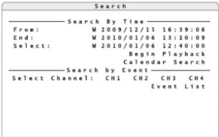
text_image
Search Search By Time From: W 2009/12/15 16:39:06 End: W 2010/01/06 13:10:09 Select: W 2010/01/06 12:40:00 Begin Playback Calendar Search Search by Event Select Channel: CH1 CH2 CH3 CH4 Event List③5 Window "Search"
2) The lines From and End show the start and the end of the period for which recordings are available. If automatic change of time has been selected in the system settings ( chapter 6.2.7), an "S" (summer time) for daylight saving time or a "W" (winter time) for standard time will appear in front of the date.
To replay the start of all recordings, activate the line From.
To replay them shortly before the end, activate the line End.
To replay recordings made at a particular point of time, enter the date and the time in the line Select and activate Begin Playback.
If there is no recording available for the time entered, the next recording available will be replayed.
3) If you do not know the precise point of time, activate the function Calendar Search (fig. 36).

text_image
Calendar Search S M T W T F S 3 4 5 6 7 8 9 10 11 12 13 14 15 16 17 18 19 20 21 22 23 24 25 26 27 28 29 30 31 Search by Time 0 4 8 12 16 20 24 Select: W2010/01/06 12:40:00③6 Window "Calendar Search"
In the top line, define the year and the month. When the month is entered, the numbers highlighted in the calendar will show the days for which recordings are available.
Select a day in the calendar. When the day is selected, the time bar at the bottom will show the periods for which recordings are available. Yellow blocks are time-controlled recordings and red blocks are recordings triggered by events (alarm recordings).
To define the desired point of time, move the arrow on the time bar or directly enter it in the line Select:. Start the replay via the icon ▶
9.1.1 Event list
In the window Search (fig. 35), it will be possible to create an event list under Search by Event.
1) In the line Select Channel:, select the camera channels to be used for creating the list.
Select the channels with the buttons and (8) and activate or deactivate each of the channels with the button ENTER (6) [or with the left mouse button]. Dark channel numbers mean that events of this channel will not be listed.
2) Start creating the list via the line Event List. Figure 37 shows an example of a list created. The entries are sorted by order of occurrence with the latest event listed at the top.
If the message "No available items!" appears instead of the submenu, no events have been stored for the camera channels selected. To
return to the search window, press the button ESC (7).
| Event List | ||||
| Date | Time | Ch | Type | |
| W 2010/02/06 | 23:54:03 | 1 | Loss | |
| W 2010/02/06 | 15:40:32 | 7 | Motion | |
| W 2010/02/06 | 13:30:40 | 4 | Motion | |
| W 2010/02/06 | 12:40:00 | 7 | Motion | |
| W 2010/01/15 | 03:56:10 | 7 | Alarm | |
| W 2010/01/05 | 13:20:02 | 1 | Alarm | |
| W 2010/01/05 | 06:12:20 | 3 | Alarm | |
| W 2010/01/02 | 22:42:05 | 4 | Motion | |
| W 2010/01/02 | 15:43:06 | 4 | Alarm | |
| W 2010/01/02 | 11:50:20 | 4 | Motion | |
| W 2010/01/02 | 10:33:21 | 7 | Motion | |
| W 2010/01/02 | 09:20:34 | 3 | Motion | |
③7 Window "Event List"
The columns Date and Time list the date and the time of the corresponding event. If automatic change of time has been selected in the system settings ( chapter 6.2.7), an "S" (summer time) for daylight saving time or a "W" (winter time) for standard time will appear in front of the date. The column Ch will indicate the number of the camera channel. The column Type will indicate the type of event:
Motion motion detection
Alarm signal at the alarm input
Loss loss of video signal
3) To start replaying the video recordings referring to this event, select the corresponding line in the list. In case of video signal loss, the last seconds before the loss will be recorded so that the cause of the video signal loss may possibly be identified.
9.2 Exporting video files
It will be possible to export a video recording, or just a part of it, to an external storage medium to replay the video file on a computer not connected to the recorder via network.
1) Connect the storage medium (e. g. USB flash drive) to the USB port (9) at the front of the recorder.
2) Start the replay of the recording.
3) At the start of the passage to be exported, press the button COPY (11). In the lower left corner of the image, "ezBurn TimeA" will appear.
4) At the end of the passage to be exported, press the button COPY again. In the lower left corner of the image, "ezBurn TimeB" will appear. The data export will start.
If the message "No exportable device detected. Please install the target device/media to the DVR." appears, no storage medium has been connected or has not correctly been recognized. It may be necessary to disconnect the USB connection and to reconnect the storage medium so that it will be recognized. Then press the button ENTER (6) or cancel with ESC (7).
To confirm recognition of the storage medium, the extent of the data to be exported will be indicated, e. g.:
ezBurn Confirmation
Selected Device: USB BAR
Exported Required Size = 15MB
Real Export Range:
From: 2010/01/13 09:51:34
To: 2010/01/13 09:52:54
The following information will be indicated: The storage medium (in this case: USB BAR), the storage space required (in this case: 15 MB) and the time when the recordings to be exported were made.
5) To start the storage process, press the button ENTER; to cancel, press the button ESC.
After successful storage, the message "Export ok!" will appear. The message will disappear when any button is pressed.
Notes
- The video files will be stored in a special format (*.DRV) and may only be reproduced with a special program. However, this program (DVR PLAYER) will also be stored on the storage
medium when exporting data and may be started directly from it.
- Depending on the size of the video sequence to be exported, the storage process may take 10 minutes to 1 hour.
9.2.1 Exporting from the event list
If the replay of a recording was started by selecting an event from the list described in chapter 9.1.1, it will not be necessary to define the start and the end of the passage to be exported. To export the video data referring to this event, press the button COPY (11) once. To confirm, the storage medium selected for export, the storage space required, the time of the event, the camera channel concerned and the type of event will be indicated.
Proceed as described above.
10 Alarm Functions
It will be possible to trigger an alarm via the internal motion detector, via an alarm input for external sensors (e.g. light barrier or motion detector), via video signal loss or when the hard disk is full or missing. The symbol (3) will light up on the recorder in this case. Depending on the configuration of the recorder, there are various responses to an alarm, e.g. start of a recording, activation of the alarm output, acoustic alarm signal, insertion of a message on the screen, switching to the full image display of the camera channel concerned, transmission of an e-mail with a short video sequence of the object triggering the alarm.
10.1 Alarm configuration
In the menu, define the events triggering an alarm and the resulting action.
1) Via the main menu (fig. 38), activate the submenu Event Setup (fig. 39).
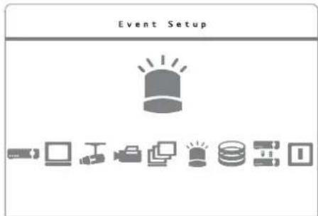
text_image
Event Setup③8 Main menu "Event Setup" selected
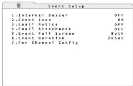
text_image
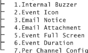
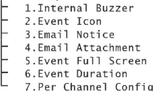
1. Internal Buzzer OFF 2. Event Icon ON 3. Email Notice OFF 4. Email Attachment OFF 5. Event Full Screen Both 6. Event Duration 20Sec 7. Per Channel Config⑲ Submenu "Event Setup"
2) In the line 1. Internal Buzzer, define if in case of alarm a buzzer will sound (ON) or not (OFF).
3) In the line 2. Event Icon, define if in case of alarm an icon corresponding to the event triggering the alarm will be inserted on the screen (ON) or not (OFF):
M = motion detection
L = signal loss
A = alarm input
4) In the line 3. Email Notice, define if in case of alarm an e-mail message will be sent (ON) or not (OFF). In the line 4. Email Attachment, define if the e-mail message will have short video sequences in AVI format as an attachment (ON) or not (OFF). For each channel concerned, an AVI file will be attached (total size approx. 2 MB).
A free computer program for reproduction is available for download on the website www.divx.com.
Notification by e-mail will require a connection of the recorder to the Internet and the correct setting of network parameters in the submenu System Setup/ Network Setup (chapter 16.1). Also enter the access data for an existing e-mail account here ( chapter 16.1.1).
5) In the line 5. Event Full Screen, define if in case of alarm the camera channel concerned will be displayed as a full image on the main monitor (Main), on the additional monitor (Call) or on both (Both) or if switching to full image display is not desired (None).
6) In the line 6. Event Duration, define the duration in seconds for the insertion of the icon, for the buzzer and for the activity of the alarm output after an event has triggered an alarm.
7) Via the line 7. Per Channel Config, activate the corresponding submenu (fig. 40) for the alarm configuration of the individual input channels.
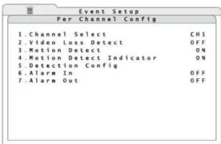
text_image
Event Setup Per Channel Config 1. Channel Select CHI 2. Video Loss Detect OFF 3. Motion Detect ON 4. Motion Detect Indicator ON 5. Detection Config 6. Alarm In OFF 7. Alarm Out OFF④0 Submenu "Per Channel Config"
8) In the line 1. Channel Select, select the channel for which the settings are to be made.
9) In the line 2. Video Loss Detect, define if in case of video signal loss an alarm will be triggered (ON) or not (OFF).
10) In the line 3. Motion Detect, define if in case of motion detection via the internal motion detector an alarm will be triggered (ON) or not (OFF).
11) In the line 4. Motion Detect Indicator, define if in case of active motion detection the grid fields where a motion was detected will be highlighted (ON) or not (OFF).
12) In the line 6. Alarm In, define if the alarm input of this channel is to be evaluated and define the contact type of the detector connected:
OFF the input will be ignored
N/0 normally open contact
N/C normally closed contact
13) In the line 7. Alarm Out, define if an alarm triggering of this channel will activate the alarm output (ON) or not (OFF).
14) If motion detection for this channel has been activated in the line 3. Motion Detect (ON), activate the submenu to configure the motion detector (fig. 41) via the line 5. Detection Config
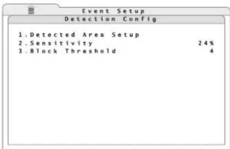
text_image
Event Setup Detection Config 1.Detected Area Setup 2.Sensitivity 24% 3.Block Threshold 4④1 Submenu "Detection Config"
15) To define the coverage, activate the line 1. Detected Area Setup. The camera image will be displayed with a grid of 16 × 12 fields over it (fig. 42). The coloured fields will mark the coverage for motion detection.
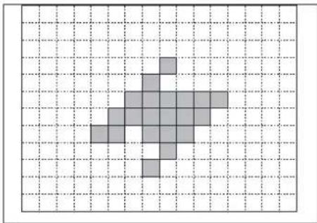
natural_image
Pixelated gray arrow shape on a grid background (no text or symbols)④2 Motion detection grid
To change a field, select it with the arrow buttons (8) and press the button ENTER (6) or click it with the mouse pointer. To make the input easier, all fields will be activated or deactivated again with the button MODE (16).
To exit the area definition, press the button ESC (7) or the right mouse button.
16) In the line 2. Sensitivity, define the sensitivity for motion detection. The higher the value, the more sensitive the response of alarm triggering.
17) In the line 3. Block Threshold, define the minimum number of grid fields where a motion must be detected before an alarm will be triggered.
11 Data Management
11.1 Deleting recordings
1) Via the main menu (fig. 29), activate the submenu Record Setup (fig. 30).
2) Via the line 9. Purge Data, activate the sub-menu to delete recordings (fig. 43).
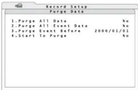
text_image
Record Setup Purge Data 1.Purge All Data No 2.Purge All Event Data No 3.Purge Event Before 2000/01/01 4.Start To Purge No④3 Submenu "Purge Data"
3) In the line 1. Purge All Data, define if all recordings on the active hard disks will be deleted (Yes) or not (No).
4) To delete only recordings triggered by an event (alarm), select the option Yes in the line 2. Purge All Event Data.
5) To delete only recordings triggered by an event (alarm) and made before a particular time, define the desired date in the line 3. Purge Event Before.
6) To start deleting, select the option Yes in the line 4. Start To Purge.
After successful deletion, the message "Purging ok" will appear. The message will disappear when any button is pressed.
11.2 Hard disk management
1) Via the main menu (fig. 44), activate the submenu Database Setup (fig. 45).
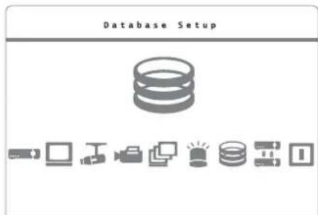
text_image
Database Setup④4 Main menu: "Database Setup" selected
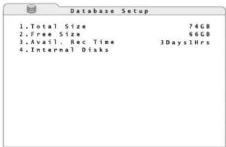
text_image
Database Setup 1.Total Size 74GB 2.Free Size 66GB 3.Avail. Rec Time 3Days1Hrs 4.Internal Disks④5 Submenu "Database Setup"
2) The line 1. Total Size will indicate the size of the entire storage space on the internal hard disks.
The line 2. Free Size will indicate the size of the free storage space on the internal hard disks.
The line 3. Avail. Rec Time will indicate the resulting maximum recording time. This time also depends on the settings for recording (chapter 8.1).
If the option "Circular Recording" for overwriting old recordings automatically has been activated in the submenu "Recording Setup" (ON), "(Circular)" will appear instead of the free storage space and the recording time available.
3) To list the internal hard disks, activate the corresponding submenu (fig. 46) via the line 4. Internal Disks.
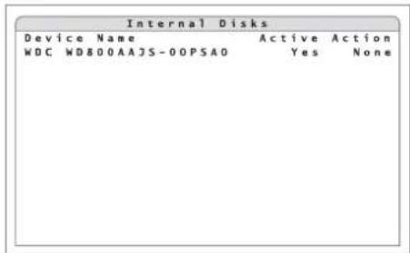
text_image
Internal Disks Device Name Active Action WDC WD800AAJS-00PSAO Yes None④6 Submenu "Internal Disks"
The column Device Name will show the names of the internal hard disks. The column Active will indicate if the corresponding hard disk is active, i.e. if it is available for recording (Yes) or not (No).
4) In the column Action, one of the following functions will be activated:
Add activation of hard disk
Remove deactivation of hard disk
Format formatting of hard disk
After successful formatting, the message "Format ok" will appear. The message will disappear when any button is pressed.
None To exit the input field without activating one of the functions above.
Notes
— Before removing a hard disk, deactivate it via the function Remove.
- Once the function Format has been selected and confirmed with the button ENTER (6) [or the left mouse button], formatting of the hard disk selected will start without prior confirmation prompt. All data on this hard disk will be deleted!
- If no hard disk has been activated and the menu is not inserted, "NO DISK" will appear in the upper right corner of the screen.
12 Camera Remote Control (DOME)
It will be possible to remote-control suitable cameras from the recorder via an RS-485 data bus at the jack IO (26) [ chapter 5.3.3]. According to the features of the camera, remote control of movements such as pan and tilt, but also focus, zoom and iris will be possible. It will even be possible to store certain camera positions or settings and to reactivate them later.
12.1 Configuring the control parameters
12.1.1 Configuring the RS-485 interface
Proceed as described below to adjust the RS-485 interface to the requirements of the cameras connected to be controlled:
1) Via the main menu (fig. 14), activate the submenu System Setup (fig. 15).
2) Via the line 7. RS485 Setup, activate the corresponding submenu (fig. 47).
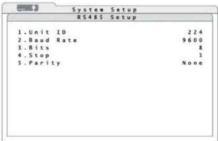
text_image
RS485 Setup 1. Unit ID 224 2. Baud Rate 9600 3. Bits 8 4. Stop 1 5. Parity None④7 Submenu "RS485 Setup"
3) In the line 1. Unit ID, enter the address of the recorder for the RS-485 data bus. Each of the units connected to one data bus must have an individual address.
4) In the other lines, define the transmission parameters of the interface:
Baud Rate data transmission rate 2400, ..., 57600 bauds
Bits number of data bits 6, 7, 8
Stop number of stop bits 1, 2
Parity parity NONE, ODD, EVEN
Note: The changes made will become effective after exiting the menu.
12.1.2 Camera settings
To set the control parameters for the individual cameras:
1) Via the main menu (fig. 19), activate the submenu Camera Setup (fig. 20).
2) In the line 1. Analog Camera Select, select the channel of the camera for which the settings will be made.
3) In the line 2. Dome Protocol, define the control protocol for the camera or select None if the camera is not to be controlled.
4) In the line 3. Dome ID, select the data bus address adjusted on the camera.
5) To set further cameras, repeat steps 2 - 4.
Note: The changes made will become effective after exiting the menu.
12.2 Controlling a camera
To control a camera during live surveillance:
1) Activate the full image display of the camera to be controlled [press the corresponding channel button (1) or click the image on the split screen with the left mouse button, chapter 7].
2) Press the button DOME (12). The insertion "Dome Control" in the lower left corner of the image shows that the camera control has been activated. In addition, a help text will be inserted showing the functions of the buttons differing in this mode. If required, deactivate or reactivate the text with the channel button 2 (1).
3) Control the camera via the following buttons:
FREEZE (14) focus far
MENU (18) zoom in
SEARCH (17) zoom out
ENTER (6) activation of autofocus and automatic iris control
channel button 1 (1) storage and reactivation
of camera settings (following chapters)
Furthermore, the buttons CALL (10) and ENTER (6) will activate the OSD menu of the camera, activate submenus in it and confirm inputs. To navigate through the OSD menu of the camera and to change settings, use the button CALL and the arrow buttons ▶, ▶, ▲, ▼ (8).
Note: It will depend on the features of the camera used which of the settings mentioned above can be remote-controlled.
4) To exit the camera control, press the button DOME or ESC.
12.2.1 Storing camera settings
Align and adjust the camera as described in chapter 12.2. To store this setting:
1) Press the button for the camera channel 1 (1). The list Dome Preset (fig. 48) will appear.
Dome Control
④8 List "Dome Preset"
2) In the column Index, select the storage location number where the camera setting will be stored. Select the option Yes in the column Set Preset behind this number.
The setting will be stored to be reactivated again. The list will disappear.
Note: The list has 256 positions. The number of storage locations actually available will depend on the corresponding camera.
12.2.2 Reactivating camera settings
Activate the mode to control a camera as described in chapter 12.2. To reactivate a camera setting stored:
1) Press the button for the camera channel 1 (1). The list Dome Preset (fig. 48) will appear.
2) In the column Index, select the storage location number where the camera setting has been stored. Select the option Yes in the column Go Preset behind this number.
The camera will be aligned according to the setting stored. The list will disappear.
In the mode "Dome Control", it will be possible to directly activate the storage positions 1 - 6 via the buttons 11 - 16 (1) without reactivating the list.
13 Password Protection
To protect the recorder against unauthorized operation, it is provided with an 8-level password protection of various configurations.
In addition to the preset user name "admin" with the highest access permission level, it will be possible to define seven user accounts with arbitrary user names, individual password and an access permission level. It will also be possible to define the
required access permission level for each of the various functions and menu areas.
To enter the user name and the password when the password protection has been activated see chapter 6.1.
13.1 Configuring the password protection
1) Activate the main menu (Chapter 6.1, fig. 14).
2) Activate the submenu System Setup (fig. 15).
3) Via the line 5. User Management, activate the corresponding submenu (fig. 49).
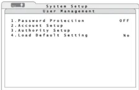
text_image
System Setup User Management 1. Password Protection OFF 2. Account Setup 3. Authority Setup 4. Load Default Setting No④9 Submenu "User Management"
4) In the line 1. Password Protection, define if the password protection will be activated (ON) or not (OFF).
5) To define the access permission levels required for the operating functions and menu areas, activate the corresponding submenu (fig. 50) via the line 3. Authority Setup.
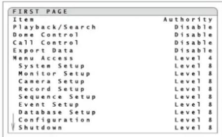
text_image
FIRST PAGE Item Authority Playback/Search Disable Done Control Disable Call Control Disable Export Data Disable Menu Access Level 4 System Setup Level 8 Monitor Setup Level 8 Camera Setup Level 8 Record Setup Level 8 Sequence Setup Level 8 Event Setup Level 8 Database Setup Level 8 Configuration Level 8 Shutdown Level 8⑤0 Submenu "Authority Setup"
For the functions Playback/Search, Dome Control, Call Control, Export Data, Menu Accesss and for the individual submenus, define in each case the minimum access permission level (Level 1-Level 8) required of a user for activating this function. If you select Disable, no password protection will be activated for this function.
Note: The option Disable will not be available for Menu Access.
6) To define the user access permissions, exit the submenu Authority Setup and activate the corresponding submenu (fig. 51) in the submenu User Management via the line 2.Account Setup.
| Account Setup | |||
| Account | ID | PWD | Authority |
| admin | Edit | Edit | Level 8 |
| user | Edit | Edit | Level 8 |
| user1 | Edit | Edit | Disable |
| user3 | Edit | Edit | Disable |
| user4 | Edit | Edit | Disable |
| user5 | Edit | Edit | Disable |
| user6 | Edit | Edit | Disable |
| user7 | Edit | Edit | Disable |
⑤1 Submenu "Account Setup"
7) The user names are listed under Account. To change a user name, click Edit in the column ID next to the name. The input window Edit UserName will appear which is similar to the input window for the user name when activating the menu with password protection (fig. 8). Enter a user name consisting of up to 14 characters in the same way as described in chapter 6.1.
8) In the column PWD of the user entered, activate the window to define the password for this user via Edit. Enter a password consisting of 4 - 8 numbers as described in chapter 6.1 and memorize it well! To confirm, enter the password a second time. If the second input is identical, the message "Passwd changing ok" will appear. If the message "Password mismatch!" appears, the input is incorrect; repeat the input of the password. The message will disappear when any button is pressed.
9) In the column Authority, enter the access permission level (Level 1 - Level 8) for this user. If Disable is selected, the user will have no access to the protected functions.
Note: It will not be possible to change the preset user name "admin" and its access permission level (Level 8); however, it is highly recommended to change the preset password "1234".
10) For resetting all settings concerning the users and the access permission levels for the operating functions to the factory settings, set the function 4. Load Default Setting in the submenu User Management to Yes. The message "Default setting loaded" will appear to confirm the reset. The message will disappear when any button is pressed.
13.2 Key lock
If the password protection has been deactivated (in the submenu "User Management", the option OFF has been selected for 1.Password Protection), it will be possible to easily protect some buttons against accidental operation.
To activate the key lock, press the button ESC (7) for more than 5 seconds in the live surveillance mode when the menu has been deactivated.
With the key lock activated, the icon ^ will appear at the bottom of the image.
Those of the buttons CALL (10), DOME (12), PLAY/ STOP (15), SEARCH (17), MENU (18) will be locked for which the function in the submenu "Authority Setup" (Chapter 13.1) has not been set to Disable.
To deactivate the key lock, press the button ESC for more than 5 seconds in the live surveillance mode.
The icon ^ will disappear.
14 Managing the Recorder Settings
It will be possible to store all system settings of the recorder made by the user on an external storage medium, to reload them or to reset them to the factory settings.
For managing the recorder settings, use the main menu (fig. 52) to activate the submenu Configuration (fig. 53).
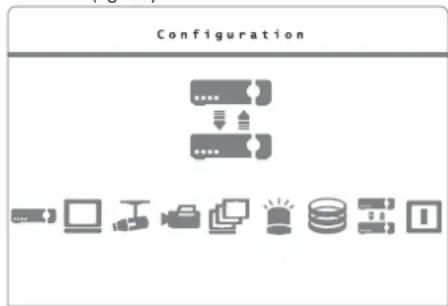
text_image
Configuration⑤2 Main menu: "Configuration" selected
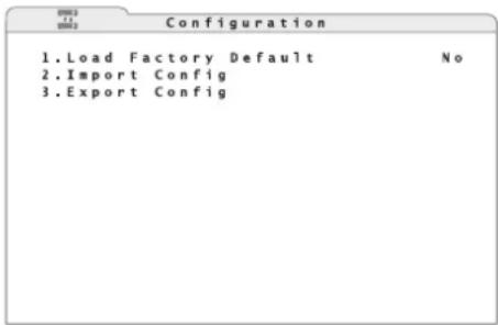
text_image
Configuration 1.Load Factory Default No 2.Import Config 3.Export Config⑤3 Submenu "Configuration"
14.1 Storing settings
The settings of the recorders will be stored on an external storage medium connected to the USB port (9) at the front of the recorder. For each storage process, it will be possible to assign an individual name to the settings so that different settings are easily distinguished.
1) Via the line 3. Export Config, activate the corresponding submenu (fig. 54).
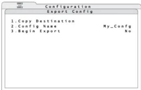
text_image
Configuration Export Config 1. Copy Destination 2. Config Name My_Config 3. Begin Export No⑤4 Submenu "Export Config"
2) Via the line 1. Copy Destination, activate the corresponding submenu (fig. 55).
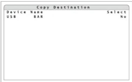
text_image
Copy Destination Device Name Select USB BAR No⑤5 Submenu "Copy Destination"
3) In the column Device Name, the names of the storage media connected (e.g. USB flash drive) will be listed.
If the message "No available items!" appears instead of the submenu, check whether or not the storage medium has been correctly connected. It may be necessary to disconnect the USB connection and to reconnect the storage medium so that it will be recognized. Select Yes in the column Select for the storage medium to be used for storing the settings. Then return to the submenu Export Config [press the button ESC (7)].
4) In the line 2. Config Name, enter a name consisting of up to 15 characters for storing the settings. Enter the name as described for the camera title (Chapter 6.2.4).
5) To store it, select the option Yes in the line 3.Begin Export.
If the settings have been correctly stored, the message "Export ok." will appear. If the message "Please specify destination first!" appears instead, you failed to define the storage location (steps 2 and 3). If "Please specify config name first!" appears, no name for storing has yet been entered (step 4).
The message will disappear when any button is pressed.

14.2 Loading settings
To load settings stored previously:
1) Via the line 2. Import Config in the submenu Configuration, activate the corresponding submenu (fig. 56).
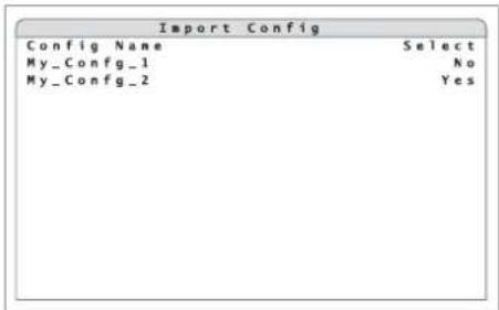
text_image
Import Config Config Name Select My_Config_1 No My_Config_2 Yes⑤6 Submenu "Import Config"
2) In the column Config Name, the names of the available settings will be listed.
If the message "No available items!" appears instead of the submenu, no storage medium (e.g. USB flash drive) containing stored settings has been connected. If this is not the case, it may be necessary to disconnect the USB connection and to reconnect the storage medium so that it will be recognized.
In the column Select, select Yes for the name of the settings to be loaded.
A warning will appear pointing out that the system will be restarted if loading of stored settings results in different recording settings. Confirm the loading of settings with the button ENTER (6) or cancel with the button ESC (7).
If the settings have been loaded successfully, the message "Import ok" will appear. The message will disappear when any button is pressed.
14.3 Resetting
Resetting to the factory settings will also be possible. When resetting, all settings made by the user will be lost irretrievably unless a backup has been made earlier on an external storage medium (E chapter 14.1).
To start resetting, select Yes in the line 1.Load Factory Default of the submenu Configuration (fig. 53).
If the factory settings have been loaded successfully, the message "Loading factory default ok" will appear. The message will disappear when any button is pressed.
15 Indication of System Information
To indicate the system information of the recorder:
1) Via the main menu (fig. 14); activate the submenu System Setup (fig. 15).
2) Via the line 1. System/Version Info, activate the corresponding submenu (fig. 57).
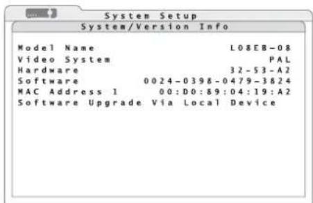
text_image
System Setup System/Version Info Model Name L08EB-08 Video System PAL Hardware 32-53-A2 Software 0024-0398-0479-3824 MAC Address 1 00:D0:89:04:19:A2 Software Upgrade Via Local Device⑤7 Submenu"System/Version Info"
The following information will be indicated:
Model Name internal model name
Video System video system currently selected with selector switch PAL/NTSC(25)
Hardware version number of recorder hardware
Software version number of recorder firmware
MAC Address hardware address of recorder (Media Access Control Address) for clear identification of the recorder in a computer network (Ethernet)
3) The line Software Upgrade via Local Device is used to update the software (firmware) of the recorder by means of a storage medium connected via USB.
Note: A firmware update is made at your own risk. If the update is not correctly installed or if it is interrupted (e.g. due to power failure), the recorder may not operate correctly any more.
16 Remote Access via Computer Network
Via its connection jack LAN (19), it will be possible to connect the video recorder to an individual computer, to a local computer network or, e. g. via a router, to the Internet. For correct configuration, knowledge of computer network technology will be essential.
16.1 Setting up a network connection
To set up a connection to a computer network:
1) Via the main menu (fig. 14), activate the submenu System Setup (fig. 15).
2) Via the line 6. Network Setup, activate the corresponding submenu (fig. 58).
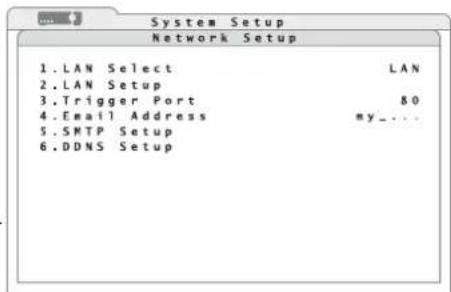
text_image
1. LAN Select 2. LAN Setup 3. Trigger Port 4. Email Address 5. SMTP Setup 6. DDNS Setup⑤8 Submenu "Network Setup"
3) In the line LAN Select, select the type of network connection:
LAN Local Area Network
PPPoE Point-to-Point Protocol over Ethernet, e. g. for a direct Internet connection via DSL modem
None
4) If required, change the port number 80 (usual port number for web servers) preset in the line 3. Trigger Port.
5) To set up the parameters required for the type of network, activate the corresponding submenu (fig. 59 or 60) via the line 2. LAN Setup.
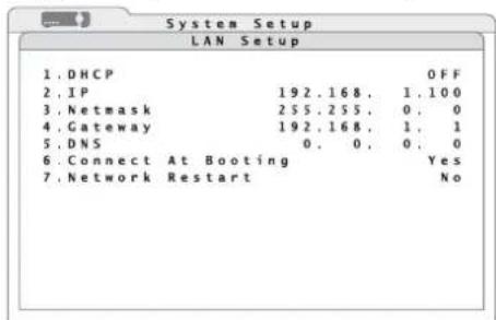
text_image
System Setup LAN Setup 1. DHCP OFF 2. IP 192.168. 1.100 3. Netmask 255.255. 0. 0 4. Gateway 192.168. 1. 1 5. DNS 0. 0. 0 6. Connect At Booting Yes 7. Network Restart No⑤9 Submenu "LAN Setup"
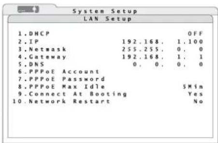
text_image
System Setup LAN Setup 1.DHCP 2.IP 192.168. 1.100 3.Netmask 255.255. 0. 0 4.Gateway 192.168. 1. 1 5.DNS 0. 0. 0. 0 6.PPPoE Account 7.PPPoE Password 8.PPPoE Max Idle 5Min 9.Connect At Booting Yes 10.Network Restart No⑥0 Submenu "LAN Setup (PPPoE)"
6) To assign the network configuration to the recorder by a DHCP server (e.g. the router), select ON in the line 1.DHCP (Dynamic Host Configuration Protocol). For manual input of the parameters 2.IP, 3.Netmask, 4.Gateway and 5.DNS, select the option OFF.
7) If PPPoE has been selected as the type of network connection, additional lines will appear in the submenu LAN Setup. In the lines 6. PPPoE Account and 7. PPPoE Password, enter the access data made available by the Internet service provider. Enter the data as described for the camera title (Chapter 6.2.4).
In the line 8.PPPoE Max Idle, enter the maximum idle time after which the modem will disconnect when the computer connected does not respond.
8) In the line 6. or 9. Connect At Booting, select automatic network connection when starting the recorder (Yes) or not (No).
9) For manual, immediate restart of the network connection, select the option Yes in the line 7. or 10. Network Restart.
16.1.1 Configuring notification via e-mail
To send an e-mail message in case of alarm to an address defined previously, make the following settings:
1) Enter the e-mail address for the message in the line 4. Email Address of the submenu Network Setup (fig. 58). Enter the address as described for the camera title ( chapter 6.2.4).
2) Via the line 5. SMTP Setup, activate the corresponding submenu (fig. 61).
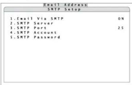
text_image
Email Address SMTP Setup 1.Email Via SMTP ON 2.SMTP Server 3.SMTP Port 2$ 4.SMTP Account 5.SMTP Password⑥1 Submenu "SMTP Setup"
3) In the line 1. Email via SMTP, define if e-mail transmission via the recorder will be possible (ON) or not (OFF).
4) In the line 2. SMTP Server, enter the mail server to be used for sending the message. Enter the server name as described for the camera title ( chapter 6.2.4).
5) In the line 3. SMTP Port, define the port number for transmission. For SMTP servers the usual port number is the preset Port 25.
6) In the line 4. SMTP Account, enter the user name for the e-mail account used.
7) In the line 5. SMTP Password, enter the password for access to the e-mail account.
16.1.2 Configuringi DDNS
For remote access, the IP address of the recorder must be known. However, many Internet service providers change it each time a connection is made (dynamic IP address). To solve this problem, use a DDNS server, i.e. a network service offered by several service providers. The recorder will be addressed via a subdomain of the DDNS server.
The use of a DDNS server will usually be configured in the router connecting the recorder to the Internet, but will also be possible with the recorder. For this recorder, the manufacturer's own DDNS server will be available.
Each time a connection is made, the router or recorder will send its current IP address to the DDNS server which will store it and accordingly route any queries made to the subdomain to the recorder.
To configure the recorder for using the manufacturer's own DDNS server:
1) In the submenu Network Setup (fig. 58), activate the corresponding submenu (fig. 62) via the line 6.DDNS Setup.
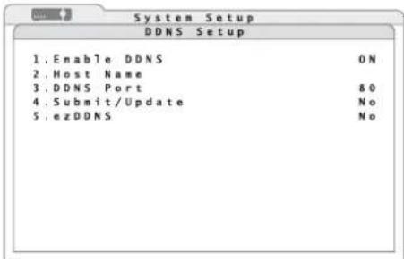
text_image
System Setup DDNS Setup 1. Enable DDNS ON 2. Host Name 3. DDNS Port &0 4. Submit/Update No 5. ezDDNS No⑥2 Submenu "DDNS Setup"
2) In the line 1. Enable DDNS, define if the recorder will use DDNS (ON) or not (OFF).
3) In the line 2.Host Name, enter the desired name for the recorder.
The name of the subdomain to address the recorder will be:
"http://[Host Name].ddns.iview-ddns.com"
When using several recorders, each recorder will require its own subdomain.
4) To make a connection to the DDNS server, select the option Yes in the line 4. Submit/Update.
5) To make it easier to log in to the DDNS server of the manufacturer, use the function ezDDNS. The "Host Name" will be assigned automatically. To start this function, select the option Yes in the line 5. ezDDNS.
Note: To execute this function, connect the recorder to the Internet via a "real" (public) IP address entered manually or assigned by a DHCP server or by port forwarding via a router.
16.2 Remote control via the programs Windows Internet Explorer or CMS
Via the network, the programs Windows Internet Explorer(IE) or the CMS (Central Management System) provided will be able to access the recorder in order to display live images of the cameras or to replay recordings, regardless of the view selected on the recorder. Furthermore, it will be possible to change settings of the recorder.
The computer used should meet the following minimum requirements:
| Processor / Memory: ..... Intel Pentium® M,1.40 GHz, 512 MB RAMrecommended:Intel® CoreTM 2Quad CPU Q66002.4 GHz, 2 GB RAM |
Hard disk memory: ..... 20 MB required for program installation
Operating system:.... Windows XP, Windows Vista
Web browser: Windows Internet Explorer, version 6 or higher
Monitor resolution: ..... 1024 × 768 pixels with 16-bit colour display
Network card: 10BASE-T (10 Mbps) or 100BASE-TX (100 Mbps)
Windows is a registered trademark of Microsoft Corporation in the U.S.A. and other countries.
This instruction manual is restricted to operation via IE. The operation of the program CMS is similar, but offers various additional functions. The comprehensive instruction manual in English is supplied on the CD together with the program.
To set up a connection from the computer to the recorder, enter the IP address of the recorder (or the public IP address of the router to which the recorder has been connected) in the address bar of the IE.
Notes
- Do not enter any leading zeroes in the individual sections of the address (e.g. enter "192.068.080.006" as "192.68.80.6").
- If the preset trigger Port 80 has been changed, e. g. to Port 81, enter the IP address as "192.68.80.6:81".
When the first connection is made via IE, the IE will download an extension required (ActiveX control element) from the recorder and will install it on the computer. If necessary, relax the security settings of the IE to permit this process:
1) Start the IE. Select the menu item "Tools" from the main menu of the browser, select "Internet Options" and click the tab "Security".
2) To define the security settings, select the menu item "Trusted Sites" and click "Sites".
3) Uncheck "Require server verification (https:) for all sites in this zone". Enter the IP address of the recorder in the field and click "Add" to add this website to the zone.
4) In the security level area, click "Custom Level".
Under "ActiveX controls and plug-ins", set all menu items to "Enable" or "Prompt".
5) Click "OK" to accept the settings and close the window "Security Settings".
For making a connection, it is also necessary to enter a user name and the corresponding password from the user accounts created in the recorder (Chapter 13.1), even if the password protection in the recorder has been deactivated.
A user logged in as "admin" and two other users may access the recorder at the same time. If a user activates the setting menu locally on the recorder as "admin" at the same time, this user will take priority over a remote access. A message stating that the recorder is being operated locally will appear on the computer.
If access is granted, the following window will appear:
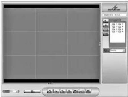
text_image
Screenshot of a software interface with a screen and toolbar, featuring a 'MORATOR' logo and a grid of icons.⑥3 Remote control window in the IE
At the beginning, in the split-screen area, all camera images will be displayed which have not been set to "covert" in the recorder (chapter 6.2.6). The camera channels will be listed on the right. Cameras to be remote-controlled via the recorder will be marked with the icon static cameras with the icon.
To view a camera as a full image, click the corresponding icon or double-click the image in the split-screen view.
To return to a split-screen arrangement, click the corresponding button:
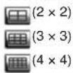
It depends on the number of input channels of the recorder connected if these display arrangements will be available.

Button to activate the transmission of the camera sound. When the sound has been activated, the icon will change to:

To deactivate the sound, click the button once again.

Button to record the video signals of the cameras currently displayed as video files on the computer, independently of recordings made by the recorder. The file format will correspond to the recording format of the recorder (file extension *.drv). First, a dialog box will open for defining the file name and the storage location. Then recording will start. The button will look as if it has been pressed. To stop the recording, click the button once again.

In the list field "Bandwidth", the update rate of the camera images will be matched to the transmission bandwidth that is available.

In the list field "Picture size", the display size of the camera images will be defined.

Button "4 : 3" to switch the display in the image area between a fixed aspect ratio (width : height = 4 : 3) and proportions depending on the size of the program window.

Button "Playback" to reproduce recordings from the recorder or to download them to the computer, provided that the user logged in is authorized. When downloading recordings, it will be possible to define the recording time and to select particular camera channels. It will also be possible to reproduce recordings from the computer and to check the authenticity of files exported from the video recorder. (To prevent manipulation, the recorder will provide the data with a digital signature. Therefore, in addition to *.drv/.*.avi video files, also files of the type *.sig and *.gpg will be stored.) While a recording is reproduced, the following buttons to control the replay will be indicated in the lower right corner:

⑥4 Replay control
The button is used to pause and continue the replay. The other two buttons will change the direction and the speed (1 ×, 2 ×, 4 ×, 8 ×, 16 ×, 32 ×) of the replay; when the replay is paused and one of the buttons is pressed, the replay will go forwards or backwards image by image.

Button "Live" to exit the replay mode and to return to live camera images.

Button "Configuration" to change the menu settings of the recorder, provided that the user logged in is authorized.

Button "Search" to indicate the event list of the recorder (see chapter 9.1.1). Download the video file for a marked list entry to the computer via the button "Download" or double-click the list entry to reproduce it immediately, provided that the user logged in is authorized.

Click "Snapshot" to store a screenshot of the current program window in the desktop directory as a "Snapshot-x.jpg" with "x" as a consecutive number.

Button "Health" to indicate status information concerning the internal hard disks and the storage media of the recorder connected via USB.

Button "Download DVRPlayer" to download a program from the
recorder to the computer which will reproduce the *.drv video files even on computers not connected to the recorder.
With a click on the corresponding buttons where operating elements on the right and below the image area will disappear and a larger image area will be available.

16.2.1 Camera remote control via IE
If a camera with remote control has been selected as a full-image display while live camera images are displayed, the field for camera control (fig. 65) will appear on the right.
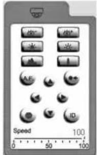
text_image
Speed 100 0 50 100⑥5 Camera control

direction control of the camera

focus setting

iris setting

zoom setting
activation of the automatic iris control / auto focus function
activation of a camera setting stored "Go preset" Select the storage location number from the list inserted.
storage of a camera setting "Set preset" Select the storage location number from the list inserted. The number of available storage locations will depend on the features of the camera used.
selection of the camera to be controlled "Dome ID" In the field "ID", select the data bus address of the desired camera; select the required control protocol in the field below it. When the parameters are changed here, it will not affect the menu setting of the recorder.
The sliding control "Dome speed" will affect the motion speed of the camera.
Note: It will depend on the features of the camera used which of the settings mentioned above can actually be remote-controlled.
16.2.2 Disconnecting
When the program window of the IE is closed, the user will be logged off and disconnected automatically.
17 Shutdown or Restart of the System
To prevent data loss or damage to the recorder, down the system before disconnecting the record from its power supply.
1) Activate the main menu (fig. 66) as described in chapter 6.1.
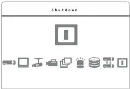
text_image
Shutdown I⑥ Main menu: "Shutdown" selected
⑥7 Submenu "Shutdown"
3) To shut down the system, select the line 1. Power Off and confirm with the button ENTER (6).
When shutting down the system, the message "System shutting down..." will flash on the screen. When the message "You can safely turn off DVR now!" appears, the process is terminated and the recorder may be disconnected from the power supply.
4) For simply restarting the recorder [e. g. after selecting the video system with the selector switch PAL / NTSC (25)], select the line 2. Reboot and confirm with the button ENTER (6). The system will be restarted.
18 Specifications
Video standard:....PAL/NTSC selectable
Video inputs
DMR-604: 4 BNC
DMR-608: 8 BNC
DMR-616: 16 BNC
Video outputs
DMR-604: 1 BNC, 1 VGA
DMR-608 / DMR-616: ... 2 BNC, 1 VGA
Audio inputs
DMR-604: 4 RCA
DMR-608: 8 via 25-pole D-Sub jack, adapter to RCA supplied
DMR-616: 16 via 25-pole D-Sub jack, adapter to RCA supplied
Audio outputs
DMR-604: 1 RCA
DMR-608 / DMR-616: ... 2 RCA
Video compression: ..... H.264
Maximum recording rate with resolution selected (pixels, horizontal × vertical)
DMR-604:
| PAL | |
| 352 × 288 | 100images/s |
| 720 × 288 | 50images/s |
| 720 × 576 | 25images/s |
| NTSC | |
| 352 × 240 | 120images/s |
| 720 × 240 | 60images/s |
| 720 × 480 | 30images/s |
DMR-608, DMR-616:
| PAL | |
| 352 × 288 | 200images/s |
| 720 × 288 | 100images/s |
| 720 × 576 | 50images/s |
| NTSC | |
| 352 × 240 | 240images/s |
| 720 × 240 | 120images/s |
| 720 × 480 | 60images/s |
Alarm inputs
DMR-604: 4, NO / NC contact, selectable
DMR-608: 8, NO / NC contact, selectable
DMR-616: 16, NO / NC contact, selectable
Alarm output: 1 change-over contact, 24V/500mA max.
Camera remote control: .. via RS-485
Protocols: .... PELCO-D, PELCO-P, Panasonic_N, Panasonic_C, JVC, Fastrax 2, AD422, DynaColor
Interfaces: 2 USB 2.0 ports for storage medium and mouse, 1 RJ45 Ethernet for computer network
Power supply: 12 V ≠5 A max. via power supply unit provided
Dimensions: 300 × 62 × 375 mm
Weight
DMR-604: 4.5 kg
DMR-608: 5 kg
DMR-616: 6 kg
Subject to technical modification.
18.1 Recording capacity
The tables below list the maximum recording times depending on the video system selected, the resolution selected, the storage capacity of the integrated hard disks, the picture rate and quality selected. They are based on permanent video recording without audio recording.
The values in the tables are based on tests and are guideline values. The actual recording capacity may vary since the compression rate of the data will depend, among other things, on the image contents of the video signals.
When recording the audio signals, e. g. for 8 channels, an additional storage capacity of approx. 8 Kbps (corresponding to 0.7 GB per day) will be required.
18.1.1 Video system PAL
68
| Recording time (days) for permanent recordingVideo system PAL, resolution 720 x 576, no audio recording | ||||||
| Hard disk capacity | Total picture rate (PPS) of all channels | Image quality selected (storage space required per image) | ||||
| Low (6 KB/ image) | Fair (10 KB/image) | Mid (14 KB/ image) | High (18 KB/ image) | Best (22 KB/ image) | ||
| 320 GB | 25 23.6 14.1 10.1 7.85 6.42 | |||||
| 12.5 47.1 28.3 20.2 15.7 12.8 | ||||||
| 6.25 94.2 56.5 40.4 31.4 25.7 | ||||||
| 500 GB | 25 37.1 22.3 15.9 12.4 10.1 | |||||
| 12.5 74.2 44.5 31.8 24.7 20.2 | ||||||
| 6.25 148 89.1 63.6 49.5 40.5 | ||||||
| 750 GB | 25 56 33.6 24 18.7 15.3 | |||||
| 12.5 112 67.1 48 37.3 30.5 | ||||||
| 6.25 224 134 95.9 74.6 61 | ||||||
| 1 TB | 25 76.6 46 32.8 25.5 20.9 | |||||
| 12.5 153 91.9 65.7 51.1 41.8 | ||||||
| 6.25 306 184 131 102 83.6 | ||||||
69
| Recording time (days) for permanent recordingVideo system PAL, resolution 720 x 288, no audio recording | ||||||
| Hard disk capacity | Total picture rate (PPS) of all channels | Image quality selected (storage space required per image) | ||||
| Low (4 KB/image) | Fair (6 KB/image) | Mid (8 KB/image) | High (10 KB/image) | Best (12 KB/image) | ||
| 320 GB | 50 17.7 11.8 8 | 83 7.06 5.89 | ||||
| 25 35.3 23.6 1 | 7.7 14.1 11.8 | |||||
| 12.5 70.6 47.1 | 35.3 28.3 23.6 | |||||
| 6.25 141 94.2 | 70.6 56.5 47.1 | |||||
| 500 GB | 50 27.8 18.6 1 | 3.9 11.1 9.28 | ||||
| 25 55.7 37.1 2 | 7.8 22.3 18.6 | |||||
| 12.5 111 74.2 | 55.7 44.5 37.1 | |||||
| 6.25 223 148 | 111 89.1 74.2 | |||||
| 750 GB | 50 42 28 21 16 | 8 14 | ||||
| 25 83.9 56 42 | 33.6 28 | |||||
| 12.5 168 112 | 83.9 67.1 56 | |||||
| 6.25 336 224 | 168 134 112 | |||||
| 1 TB | 50 57.5 38.3 2 | 8.7 23 19.2 | ||||
| 25 115 76.6 5 | 7.5 46 38.3 | |||||
| 12.5 230 153 | 15 91.9 76.6 | |||||
| 6.25 460 306 | 230 184 153 | |||||
70
| Recording time (days) for permanent recordingVideo system PAL, resolution 352 x 288, no audio recording | ||||||
| Hard disk capacity | Total picture rate (PPS) of all channels | Image quality selected (storage space required per image) | ||||
| Low (2 KB/image) | Fair (3 KB/image) | Mid (4 KB/image) | High (5 KB/image) | Best (6 KB/image) | ||
| 320 GB | 100 17.7 11.8 8 | 8.83 7.06 5.89 | ||||
| 50 35.3 23.6 1 | 7.7 14.1 11.8 | |||||
| 25 70.6 47.1 3 | 5.3 28.3 23.6 | |||||
| 12.5 141 94.2 | 70.6 56.5 47.1 | |||||
| 6.25 283 188 | 141 113 94.2 | |||||
| 500 GB | 100 27.8 18.6 | 13.9 11.1 9.28 | ||||
| 50 55.7 37.1 2 | 7.8 22.3 18.6 | |||||
| 25 111 74.2 5 | 5.7 44.5 37.1 | |||||
| 12.5 223 148 | 111 89.1 74.2 | |||||
| 6.25 445 297 | 223 178 148.4 | |||||
| 750 GB | 100 42 28 | 21 16.8 | 14 | |||
| 50 83.9 56 | 42 33 | 6 28 | ||||
| 25 168 112 83 | 9 67.1 56 | |||||
| 12.5 336 224 | 168 134 112 | |||||
| 6.25 671 448 | 336 269 224 | |||||
| 1 TB | 100 57.5 38.3 | 28.7 23 | 19.2 | |||
| 50 115 76.6 5 | 7.5 46 | 38.3 | ||||
| 25 230 153 1 | 5 91.9 76.6 | |||||
| 12.5 460 306 | 230 184 153 | |||||
| 6.25 919 613 | 460 368 306 | |||||
18.1.2 Video system NTSC
71
| Recording time (days) for permanent recordingVideo system NTSC, resolution 720 x 480, no audio recording | ||||||
| Hard disk capacity | Total picture rate (PPS) of all channels | Image quality selected (storage space required per image) | ||||
| Low (6 KB/image) | Fair (10 KB/image) | Mid (14 KB/image) | High (18 KB/image) | Best (22 KB/image) | ||
| 320 GB | 30 | 19.6 11.8 8.41 | 6.54 5.35 | |||
| 15 | 39.2 23.6 | 16.8 | 13.1 10.7 | |||
| 7.5 78.5 | 47.1 33.6 | 26.2 | 21.4 | |||
| 500 GB | 30 | 30.9 | 18.6 | 13.3 | 10.3 | 8.43 |
| 15 | 61.9 | 37.1 26.5 | 20.6 16.9 | |||
| 7.5 | 124 | 74.2 | 53 | 41.2 | 33.7 | |
| 750 GB | 30 | 46.6 | 28 | 20 | 15.5 | 12.7 |
| 15 | 93.3 | 56 | 40 | 31.1 | 25.4 | |
| 7.5 | 186 | 112 | 79.9 | 62.2 | 50.9 | |
| 1 TB | 30 | 63.8 | 38.3 27.4 | 21.3 17.4 | ||
| 15 | 128 | 76.6 | 54.7 | 42.6 | 34.8 | |
| 7.5 | 255 | 153 | 109 | 85.1 | 69.6 | |
72
| Recording time (days) for permanent recordingVideo system NTSC, resolution 720 x 240, no audio recording | ||||||
| Hard disk capacity | Total picture rate (PPS) of all channels | Image quality selected (storage space required per image) | ||||
| Low (4 KB/image) | Fair (6 KB/image) | Mid (8 KB/image) | High (10 KB/image) | Best (12 KB/image) | ||
| 320 GB | 60 | 14.7 | 9.81 | 7.36 | 5.89 | 4.91 |
| 30 | 29.4 | 19.6 | 14.7 | 11.8 | 9.81 | |
| 15 | 58.9 | 39.2 | 29.4 | 23.6 | 19.6 | |
| 7.5 | 118 | 78.5 | 58.9 | 47.1 | 39.2 | |
| 500 GB | 60 | 23.2 | 15.5 | 11.6 | 9.28 | 7.73 |
| 30 | 46.4 | 30.9 | 23.2 | 18.6 | 15.5 | |
| 15 | 92.8 | 61.9 | 46.4 | 37.1 | 30.9 | |
| 7.5 | 186 124 | 92.8 74.2 | 61.9 | |||
| 750 GB | 60 | 35 | 23.3 | 17.5 | 14 | 11.7 |
| 30 | 69.9 | 46.6 | 35 | 28 | 23.3 | |
| 15 | 140 | 93.3 | 69.9 | 56 | 46.6 | |
| 7.5 | 280 186 140 112 | 93.3 | ||||
| 1 TB | 60 | 47.9 | 31.9 | 23.9 | 19.2 | 16 |
| 30 | 95.7 | 63.8 | 47.9 | 38.3 | 31.9 | |
| 15 | 191 128 | 95.7 76.6 | 63.8 | |||
| 7.5 | 383 255 191 153 | 128 | ||||
73
| Recording time (days) for permanent recordingVideo system NTSC, resolution 352 x 240, no audio recording | ||||||
| Hard disk capacity | Total picture rate (PPS) of all channels | Image quality selected (storage space required per image) | ||||
| Low (2 KB/image) | Fair (3 KB/image) | Mid (4 KB/image) | High (5 KB/image) | Best (6 KB/image) | ||
| 320 GB | 120 14.7 9.81 7 | .36 5.89 4.91 | ||||
| 60 29.4 19.6 | 4.7 11.8 9.81 | |||||
| 30 58.9 39.2 | 29.4 23.6 19.6 | |||||
| 15 118 78.5 5 | 8.9 47.1 39.2 | |||||
| 7.5 235 157 | 118 94.2 78.5 | |||||
| 500 GB | 120 23.2 15.5 | 11.6 9.28 7.73 | ||||
| 60 46.4 30.9 | 23.2 18.6 15.5 | |||||
| 30 92.8 61.9 | 46.4 37.1 30.9 | |||||
| 15 186 124 9 | 2.8 74.2 61.9 | |||||
| 7.5 371 247 | 186 148 124 | |||||
| 750 GB | 120 35 23.3 17 | 5 14 11.7 | ||||
| 60 69.9 46.6 | 35 28 23.3 | |||||
| 30 140 93.3 6 | 9.9 56 46.6 | |||||
| 15 280 186 1 | 40 112 93.3 | |||||
| 7.5 559 373 | 280 224 186 | |||||
| 1 TB | 120 47.9 31.9 | 23.9 19.2 16 | ||||
| 60 95.7 63.8 | 47.9 38.3 31.9 | |||||
| 30 191 128 9 | 5.7 76.6 63.8 | |||||
| 15 383 255 1 | 91 153 128 | |||||
| 7.5 766 511 | 383 306 255 | |||||
⑤ prise Sub-D 15 pôles, "IO"
⑥ prise Sub-D 25 pôles, "IO"
Configuration prise Sub-D
(uniquement DMR-608 et DMR-616):
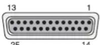
⑦ Prise Sub-D 25 pôles "AUDIO"
1 entrée audio canal 1
2 entrée audio canal 3
3 entrée audio canal 5
4 entrée audio canal 7
5 entrée audio canal 9 (uniquement DMR-616)
6 entrée audio canal 11 (uniquement DMR-616)
7 entrée audio canal 13 (uniquement DMR-616)
8 entrée audio canal 15 (uniquement DMR-616)
9–12 masse
13 non utilisé
14 entrée audio canal 2
15 entrée audio canal 4
16 entrée audio canal 6
17 entrée audio canal 8
18 entrée audio canal 10 (uniquement DMR-616)
19 entrée audio canal 12 (uniquement DMR-616)
20 entrée audio canal 14 (uniquement DMR-616)
21 entrée audio canal 16 (uniquement DMR-616)
22–24 masse
25 non utilisé
contact commun = contact 2
text_image
Input Username admin A B C D E F G H I J K L M N O P Q R S T U V W X Y Z a b c d e f g h i j k l n n o p q r s t u v w x y z 0 1 2 3 4 5 6 7 8 9 . ! 0- - , " + = *
◀ ▶ Backspace Delete Cancel OKtext_image
Password Verification Press Channel Keys To Enter Password (4-8 Digits) Press◀Key To Deletetext_image
System Setup⑩ menu principal
| 1.Show Camera Title |
| 2.Screen Center Adjust |
| 3.VGA Resolution |
| 4.Show Color Bar |
Camera Setup
| 1.Analog Camera Select |
| 2.Dome Protocol |
| 3.Dome ID |
| 4.Camera Title |
| 5.Covert |
| 6.Brightness |
| 7.Contrast |
| 8.Saturation |
| 9.Hue |
Record Setup
| 1.Record Mode Setup |
| 2.Schedule Setup |
| 3.Preset Config |
| 4.Per Camera Config |
| 5.ezRecord Setup |
| 6.Data Lifetime |
| 7.Circular Recording |
| 8.Audio Recording |
| 9.Purge Data |
Sequence Setup
| 1.Main Monitor Dwell | |
| 2.Main Monitor Schedule | |
| 3.Call Monitor Dwell | |
| 4.Call Monitor Schedule |
Event Setup
| 1. Internal Buzzer |
| 2. Event Icon |
| 3. Email Notice |
| 4. Email Attachment |
| 5. Event Full Screen |
| 6. Event Duration |
| 7. Per Channel Config |
Database Setup
| 1.Total Size |
| 2.Free Size |
| 3.Avail.Rec Time |
| 4.Internal Disks |
Configuration
| 1.Load Factory Default |
| 2.Import Config |
| 3.Export Config |
Shutdown
| E | 1.Power Off2.Reboot |
⑬ structure du menu
text_image
System Setuptext_image
Monitor Setuptext_image
1.Show Camera Title Yes 2.Screen Center Adjust 3.VGA Resolution 1280*1024 4.Show Color Bar Execute⑱ sous-menu "Monitor Setup"
text_image
Camera Setuptext_image
Camera Title Ch1 A B C D E F G H I J K L M N O P Q R S T U V W X Y Z a b c d e f g h i j k l n n o p q r s t u v w x y z 0 1 2 3 4 5 6 7 8 9 . ! 0- - , " + = *
◀ ▶ Backspace Delete Cancel OKtext_image
System Setup Daylight Saving Time Setup 1.Daylight Saving Time ON 2.DST Start Mar,Last Sun,01:00 3.DST End Mar,Last Sun,01:00 4.DST Bias 60Min②3 sous-menu "Daylight Saving Time Setup"
text_image
Unit Name My_DMR-608 A B C D E F G H I J K L M N O P Q R S T U V W X Y Z a b c d e f g h i j k l m n o p q r s t u v w x y z 0 1 2 3 4 5 6 7 8 9 . ! @- , " + = *
◀ ▶ Backspace Delete Cancel OKtext_image
Sequence Setuptext_image
Sequence Setup Main Monitor Schedule 1▶ 2▶ 3▶ 4▶ 5▶ 6▶ 7▶ 8 Press Channel Keys To Select Channel Press Key To Delete⑳ sous-menu "Main Monitor Schedule"
text_image
Record Setuptext_image
Record Setup ezRecord Setup How Many Days To Record 25Days Daytime Record Yes Night Record Yes Weekend Record Yes Record Info Average Normal PPS 1 Average Normal Quality Best③2 sous-menu "ezRecord Setup"
text_image
Record Setup Per Camera Config Camera Select CH1 Day Night Weekend Normal PPS 25 6.25 6.25 Normal Qlty Best Best Best Event Max PPS 25 25 25 Event Qlty Best Best Best Event Act Both Both Both 25 25 Both③3 sous-menu "Per Camera Config"
text_image
Search —— Search By Time ——— From: W 2009/12/15 16:39:06 End: W 2010/01/06 13:10:09 Select: W 2010/01/06 12:40:00 Begin Playback Calendar Search —— Search by Event ——— Select Channel: CH1 CH2 CH3 CH4 Event List③5 fenêtre "Search"
| Event List | ||||
| Date | Time | Ch | Type | |
| W 2010/02/06 | 23:54:03 | 1 | Loss | |
| W 2010/02/06 | 15:40:32 | 7 | Motion | |
| W 2010/02/06 | 13:30:40 | 4 | Motion | |
| W 2010/02/06 | 12:40:00 | 7 | Motion | |
| W 2010/01/15 | 03:56:10 | 7 | Alarm | |
| W 2010/01/05 | 13:20:02 | 1 | Alarm | |
| W 2010/01/05 | 06:12:20 | 3 | Alarm | |
| W 2010/01/02 | 22:42:05 | 4 | Motion | |
| W 2010/01/02 | 15:43:06 | 4 | Alarm | |
| W 2010/01/02 | 11:50:20 | 4 | Motion | |
| W 2010/01/02 | 10:33:21 | 7 | Motion | |
| W 2010/01/02 | 09:20:34 | 3 | Motion | |
Selected Device: USB BAR
Exported Required Size = 15MB
Real Export Range:
From: 2010/01/13 09:51:34
To: 2010/01/13 09:52:54
text_image
Event Setuptext_image
1. Internal Buzzer OFF 2. Event Icon ON 3. Email Notice OFF 4. Email Attachment OFF 5. Event Full Screen Both 6. Event Duration 20Sec 7. Per Channel Config⑲ sous-menu "Event Setup"
N/0 contact fermeture (normally open)
N/C contact ouverture (normally closed)
natural_image
Abstract geometric pattern of gray squares arranged in a cross shape on a dotted grid background (no text or symbols)text_image
Internal Disks Device Name Active Action WDC WD800AAJS-00PSAO Yes None④6 sous-menu "Internal Disks"
| Account Setup | |||
| Account | ID | PWD | Authority |
| admin | Edit | Edit | Level 8 |
| user | Edit | Edit | Level 8 |
| user1 | Edit | Edit | Disable |
| user3 | Edit | Edit | Disable |
| user4 | Edit | Edit | Disable |
| user5 | Edit | Edit | Disable |
| user6 | Edit | Edit | Disable |
| user7 | Edit | Edit | Disable |
⑤1 sous-menu "Account Setup"
text_image
Configurationtext_image
System Setup System/Version Info Model Name L08EB-08 Video System PAL Hardware 32-53-A2 Software 0024-0398-0479-3824 MAC Address 1 00:00:00:00:00:00:00:00:00:00:00:00:00:00:00:00:00:00:00:00:00:00:00:00:00:00:00:00:00:00:00:00:00:00:1 Software Upgrade Via Local Device⑤7 sous-menu "System/Version Info"
text_image
Screenshot of a software interface with Chinese labels, showing a grid-based control panel and buttons.text_image
Shutdown Itext_image
Input UserName admin A B C D E F G H I J K L M N O P Q R S T U V W X Y Z a b c d e f g h i j k l n n o p q r s t u v w x y z 0 1 2 3 4 5 6 7 8 9 , ! 0- - , " + = *
◀ ▶ Backspace Delete Cancel OKtext_image
Password Verification Press Channel Keys To Enter Password (4-8 Digits) Press◀ Key To Delete⑨Finestra per digitare la password
text_image
System Setup⑩ Menù principale
text_image
1. Internal Buzzer 2. Event Icon 3. Email Notice 4. Email Attachment 5. Event Full Screen 6. Event Duration 7. Per Channel ConfigDatabase Setup
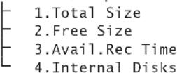
Configuration
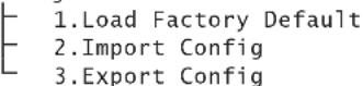
Shutdown
text_image
System Setuptext_image
Monitor Setuptext_image
Monitor Setup 1.Show Camera Title Yes 2.Screen Center Adjust 3.VGA Resolution 1280*1024 4.Show Color Bar Execute⑱ Sottomenù "Monitor Setup"
text_image
Camera Setuptext_image
Camera Title Ch1 A B C D E F G H I J K L M N O P Q R S T U V W X Y Z a b c d e f g h i j k l m n o p q r s t u v w x y z 0 1 2 3 4 5 6 7 8 9 , ! 0- - , " + = *
◀ ▶ Backspace Delete Cancel OK②1Finestra d'input "Camera Title"
text_image
System Setup Daylight Saving Time Setup 1.Daylight Saving Time ON 2.DST Start Mar,Last Sun,01:00 3.DST End Mar,Last Sun,01:00 4.DST Bias 60Min②3 Sottomenù "Daylight Saving Time Setup"
text_image
Unit Name My_DMR-608 A B C D E F G H I J K L M N O P Q R S T U V W X Y Z a b c d e f g h i j k l m n o p q r s t u v w x y z 0 1 2 3 4 5 6 7 8 9 . ! 0- , " + = *
◀ ▶ Backspace Delete Cancel OKtext_image
Sequence Setuptext_image
Sequence Setup Main Monitor Schedule 1▶ 2▶ 3▶ 4▶ 5▶ 6▶ 7▶ 8 Press Channel Keys To Select Channel Press Key To Delete⑳ Sottomenù "Main Monitor Schedule"
text_image
Record Setuptext_image
Record Setup ezRecord Setup How Many Days To Record 25Days Daytime Record Yes Night Record Yes Weekend Record Yes Record Info Average Normal PPS 1 Average Normal Quality Best③2 Sottomenù "ezRecord Setup"
| Record Setup | ||||
| Per Camera Config | ||||
| Camera Select | CH1 | |||
| Day | Night | Weekend | ||
| Normal | PPS | 25 | 6.25 | 6.25 |
| Normal | Qlty | Best | Best | Best |
| Event | Max PPS | 25 | 25 | 25 |
| Event | Qlty | Best | Best | Best |
| Event | Act | Both | Both | Both |
text_image
Search Search By Time From: W 2009/12/15 16:39:06 End: W 2010/01/06 13:10:09 Select: W 2010/01/06 12:40:00 Begin Playback Calendar Search Search by Event Select Channel: CH1 CH2 CH3 CH4 Event List| Event List | ||||
| Date | Time | Ch | Type | |
| W 2010/02/06 | 23:54:03 | 1 | Loss | |
| W 2010/02/06 | 15:40:32 | 7 | Motion | |
| W 2010/02/06 | 13:30:40 | 4 | Motion | |
| W 2010/02/06 | 12:40:00 | 7 | Motion | |
| W 2010/01/15 | 03:56:10 | 7 | Alarm | |
| W 2010/01/05 | 13:20:02 | 1 | Alarm | |
| W 2010/01/05 | 06:12:20 | 3 | Alarm | |
| W 2010/01/02 | 22:42:05 | 4 | Motion | |
| W 2010/01/02 | 15:43:06 | 4 | Alarm | |
| W 2010/01/02 | 11:50:20 | 4 | Motion | |
| W 2010/01/02 | 10:33:21 | 7 | Motion | |
| W 2010/01/02 | 09:20:34 | 3 | Motion | |
③7 Finestra "Event List"
Selected Device: USB BAR
Exported Required Size = 15MB
Real Export Range:
From: 2010/01/13 09:51:34
To: 2010/01/13 09:52:54
text_image
Event Setuptext_image
1. Internal Buzzer OFF 2. Event Icon ON 3. Email Notice OFF 4. Email Attachment OFF 5. Event Full Screen Both 6. Event Duration 20Sec 7. Per Channel Config⑲ Sottomenù "Event Setup"
N/C contatto di riposo NC (normally closed)
natural_image
Abstract geometric pattern of gray squares on a dotted grid background (no text or symbols)text_image
Internal Disks Device Name Active Action WDC WD&00AAJS-00PSAO Yes None④6 Sottomenù "Internal Disks"
| Account Setup | |||
| Account | ID | PWD | Authority |
| admin | Edit | Edit | Level 8 |
| user | Edit | Edit | Level 8 |
| user1 | Edit | Edit | Disable |
| user3 | Edit | Edit | Disable |
| user4 | Edit | Edit | Disable |
| user5 | Edit | Edit | Disable |
| user6 | Edit | Edit | Disable |
| user7 | Edit | Edit | Disable |
⑤1 Sottomenü "Account Setup"