BO710 - Cooker BOMPANI - Free user manual and instructions
Find the device manual for free BO710 BOMPANI in PDF.

User questions about BO710 BOMPANI
0 question about this device. Answer the ones you know or ask your own.
Ask a new question about this device
Download the instructions for your Cooker in PDF format for free! Find your manual BO710 - BOMPANI and take your electronic device back in hand. On this page are published all the documents necessary for the use of your device. BO710 by BOMPANI.
USER MANUAL BO710 BOMPANI
Instructions for use and maintenance of gas, gas-electric and electric cookers. Series:
RU
PyKOBODCTBO NO yCTaHOBKe H 3KcJIpyaTaUHN Ra3OBbIX,PyKOM6HnHnPOBaHHbIX H 3JIeKTPnueCKHX PJIHT. CepHH:KOM6H
PT
ACCENSIONEL BRUCIATORE FORNO
1,0 kW - Plaque Normale
1,5 kW - Plaque Rapide
0 180
1,5 kW - Plaque Normale
2,0 kW - Plaque Rapide
PUISSANCES DES ELEMENTS
résistance sole
1,5 kW
résistance plafond
0.7 kW
RECOMMANDATIONS IMPORTANTES:
FOURS AVEC THERMOSTAT
Technical data and specifications. 28
Installation 29 - 32
Ventilation 29
Positioning. 29
Gas connection 29
Adapting to different types of gas. 30
Replacing the injectors 30
Regulating the air 30
Minimum setting 30
Electrical connection 31
Electric ignition 31
Safety device. 31
For the user 32 - 38
Ventilation 32
Igniting the burners 32
Igniting the gas oven 32
Igniting the gas grill 33
Safety device. 33
Electrical switch-on. 33
Using the gas hob 33
Using the electric hot-plates .... 33
Using the gas oven. 34
Using the gas or electric grill ... 34
Using the static electric oven... 35
Using the electric fan oven .... 35
Using the multifunction electric oven with 4 cooking programs. 35
Using the multi-function electric oven 36
Using the rotisserie. 37
Oven with thermostat 37
Using the minute minder 37
Using the single-control cooking timer 37
Warming compartment 37
Advice and precautions 37
Figures 78-80
Introduction
-
Thank you for choosing one of our quality products, capable of giving you the very best service. To make full use of its performance features, read the parts of this manual which refer to your appliance carefully. The Manufacturer declines all responsibility for injury or damage caused by poor installation or improper use of the appliance.
-
To ensure its appliances are always at the state of the art, and/or to allow constant improvement in quality, the manufacturer reserves the right to make modifications without notice, although without creating difficulties for users.
- When ordering spare parts, inform your dealer of the model number and serial number punched on your appliance's nameplate, visible inside the warming compartment or on the back of the cooker.
-
APPLIANCE COMPLYING WITH THE FOLLOWING DIRECTIVES:
-
EEC 90/396
- EEC 73/23 and 93/88
- EEC 89/336 (radio-frequency interference)
- EEC 89/109 (contact with foods)
FOREWORD
Refer only to the headings and sections covering accessories actually installed on your cooker.
GB Technical data and specifications
| Nominal external C dimensions 50x50 | ookers C okers 54x54 | |
| Height at hob cm 85,0 | cm 85,0 | |
| Height with lid raised c | cm 133,0 cm | 137,0 |
| Height w. glass lid raised | cm 133,3 cm | 137,5 |
| Depth with door closed | cm 50,0 c | 54,0 |
| Depth with door open | cm 96,0 cm | 100,0 |
| Width cm 50,0 cm 54,0 | ||
| Usable Oven dimensions | Fan dimensions | oven |
| Width | cm. 39,5 | cm. 39,5 |
| Depth | cm. 42,0 | cm. 40,0 |
| Height | cm. 31,5 | cm. 31,5 |
| Volume | I. 52,0 | I. 50,0 |
GAS BURNERS (injectors and flow-rates)
| Gas | Burner | Injector | low flow-rate (kW) | nominal flow-rate (kW) |
| G20 | auxiliary | 70 | 0,40 | 0,90 |
| 20 | semi-rapid | 99 | 0,40 | 1,85 |
| mbar | rapid | 126 | 0,85 | 3,00 |
| oven | 130 | 1,00* | 3,00 | |
| grill 110 | 2,00 | |||
| G30 | auxiliary | 48 | 0,40 | 0,90 |
| 28-30 | semi-rapid | 68 | 0,40 | 1,85 |
| mbar | rapid | 86 | 0,85 | 3,00 |
| G31 | oven | 86 | 1,00* | 3,00 |
| 37 | grill 70 | 2,00 | ||
| mbar |
- For thermostat. In case of oven with tap: 1.3 kW
ELECTRIC HOTPLATES
0 145 1,0 kW - Normal hotplate 1,5 kW - Rapid hotplate
0 180 1,5 kW - Normal hotplate 2,0 kW - Rapid hotplate
HEATING ELEMENT POWERS
| bottom element | 1.5 kW |
| top element | 0.7 kW |
| oven circular element | 2.0 kW |
| grill | 2.0 kW |
| fan | 25 W |
| oven light | 15 W |
Cat.: see nameplate on cover; Class 1 or 2.1
Type "X" cookers
EQUIPMENT
All models are equipped with safety device for oven and grill burners.
Depending on the models, cooker may also have:
- Safety device for one or more hob burners
- Electric ignition on top burners
- Electric ignition on oven and grill burners
- Oven thermostat (or tap)
- Electric oven lighting
- Rotisserie
- Grill burner
- Mechanical timer
- Single-control end of cooking timer
- One or more electric hotplates
For the LAYOUT OF HOB BURNERS see the models illustrated in figure 1 at the back of this manual.
For the ELECTRIC WIRING DIAGRAM see figure 2 at the back of this manual.
The electrical power is stated on the nameplate visible inside the warming compartment (if present) or on the back of the cooker.
A copy of the nameplate is glued to the cover of this manual (for gas or gas-electric products only).
GB
Installation
INSTALLATION
The appliance must be installed by qualified staff working in accordance with the regulations in force.
Before installing, ensure that the appliance is correctly preset for the local distribution conditions (gas type and pressure).
The presettings of this appliance are indicated on the nameplate shown on the cover. This appliance is not connected to a flue gas extractor device. It must be installed and connected in accordance with the regulations in force.
This appliance may only be installed and may only operate in rooms permanently ventilated in accordance with national regulations in force.
VENTILATION
The rooms in which gas appliances are installed must be well ventilated in order to allow correct gas combustion and ventilation. The air flow necessary for combustion is at least 2m^3 /h for each kW of rated power.
POSITIONING
Remove the packaging accessories, including the films covering the chrome-plated and stainless steel parts, from the cooker.
Position the cooker in a dry, convenient and draft-free place. Keep at an appropriate distance from walls which may be damaged by heat (wood, linoleum, paper, etc.).
The cooker may be free-standing (class 1) or between two units (in class 2 st 2-1) the sides of which must withstand a temperature of 100^ and which must not be higher than the working table.
CONNECTING TO THE GAS SUPPLY
Before connecting the cooker, check that it is preset for the gas to be used. Otherwise, make the conversion as described in the section headed "Adapting to different gas types". The connection is on the right; if the pipe has to pass behind the cooker, it must be kept low down where the temperature is
about 50^
- Rigid connection (see fig. 3 A + B)
The connection to the mains gas supply may be made using a rigid metal pipe or with a metal hose. Remove the hose connector (if already fitted) and screw the rigid union onto the threaded connection of the gas train (see fig. 3A). The union for rigid connection may already be fitted on the gas train, or may be amongst the cooker accessories. Otherwise, it can be obtained from your dealer.
If national regulations permit, a metal hose complying with the national standards can be screwed directly onto the threaded connection of the gas train, fitting a seal (see fig. 3B). However, users are strongly recommended always to fit the rigid union. - Connection using a rubber hose (see fig. 3C). (For butane/propane gas only).
Connect a rubber hose carrying the conformity mark currently in force to the hose connector. The hose must be replaced at the date indicated at the latest, and must be secured at both ends using standard hose clamps. It must be absolutely accessible to allow its condition to be checked along its entire length.
CAUTION:
- Use of the hose connector is only permitted for free-standing installation. If the appliance is installed between two class 2 st. 2-1 unions, the rigid union is the only form of connection permitted.
IMPORTANT: - After installation, check that the connections are airtight.
- For operation with butane/propane, check that the gas pressure is as indicated on the nameplate.
- Use only standard rubber hoses. For LPG, use a hose which complies with the national regulations in force.
- Avoid sharp bends in the pipe and keep it well way from hot surfaces.
References to the regulations covering the gas connection to the appliance: ISO 7-1.
ADAPTING TO DIFFERENT TYPES OF GAS
If the cooker is not already preset to operate with the type of gas available, it must be converted. Proceed as follows:
- Replace the injectors (see table on page 24);
- regulate the primary air flow;
- regulate the minimum settings.
N.B.: every time you change the type of gas, indicate the new type of gas on the serial number label.
REPLACING THE HOB BURNER INJECTORS (fig. 4)
- Remove the lid of the cooker by lifting it off its supports;
- remove the grids, burner caps and burners, lifting them off;
- unscrew the 2 screws (above) or nuts (below) at the back which secure the work top, and pull it out forward.
- remove the mixer pipes and replace the injectors using a 7 mm socket wrench.
REPLACING THE OVEN BURNER INJECTOR (Fig. 5)
- Loosen the screw which secures the bottom of the oven;
- remove the oven bottom (pulling it forward);
- remove the oven burner, after taking out the screw which secures it;
- replace the injector using a 7 mm socket wrench.
REPLACING THE GRILL BURNER INJECTOR (Fig. 6)
- Remove the burner after taking out the two screws which secure it;
- replace the injector using a 7 mm socket wrench.
IMPORTANT:
- Never over-tighten the injectors;
- after replacing, check that all the injectors are airtight.
REGULATING THE BURNER AIR
Refer to the table below (indicative values) for regulation of the gap H in mm (fig. 4 for the hob, fig. 6 for the grill).
| Burner G20 | 20mbar G30 | 28-30mbar G31 37mbar |
| Auxiliary 3 | 4 | |
| Semi-rapid 3 | 3 | |
| Rapid 4 6 | ||
| Oven - - | ||
| Grill 3 8 |
Check operation of the burner:
- Ignite the burner at maximum flame;
- the tongue of the flame must be clear and with no yellow tip, and must adhere closely to the burner. If too much air is supplied, the flame detaches from the burner and may be dangerous. If the air supply is insufficient, the flame has a yellow tip and soot may form.
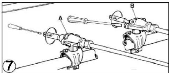
SETTING HOB BURNER MINIMUM LEVELS
If the cooker is to work on bottled gas (butane/propane), the tap by-pass must be screwed right down.
The cooker may be equipped with type A taps, with by-pass inside (accessed by inserting a small screwdriver into the rod) or type B taps, with by-pass on the outside on the right (accessed directly). See figure 7.
If the cooker is to work on natural gas, proceed as follows for both types of tap:
- Ignite the burner at maximum flame;
- pull off the knob, without using a lever against the control panel, which might be damaged;
- access the by-pass with a small screwdriver and back off by about 3 turns (turning the screwdriver anti-clockwise);
- turn the tap rod anti-clockwise again until it stops: the burner will be at maximum flame;
- screw the by-pass slowly back in, without pushing the screw-driver, until the flame has apparently shrunk to 1/4 of the maximum size, checking that it is sufficiently stable
GB
Installation
even in quite strong draughts.
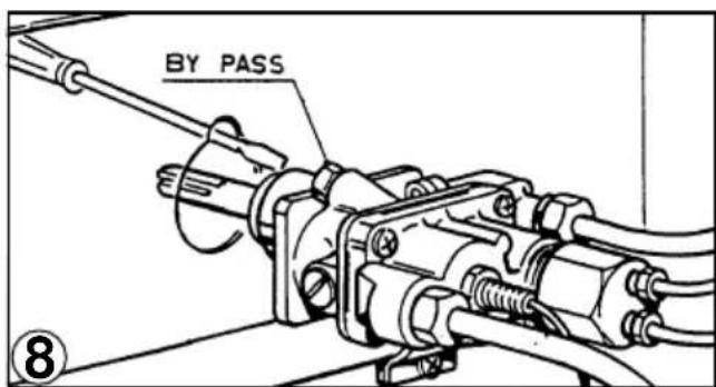
SETTING OVEN BURNER MINIMUM LEVELS
If the cooker is to work on bottled gas (butane/propane), the thermostat by-pass must be screwed right down.
If the cooker is to work on natural gas, proceed as follows:
- Remove the oven bottom (loosen the screw to remove the bottom);
- ignite the oven burner, turning the knob pointer to the maximum setting;
- shut the oven door;
- access the thermostat or tap by-pass (see fig. 8);
- back off the thermostat by-pass by about 3 turns;
- after 5 or 6 minutes, turn the knob pointer to the minimum setting;
- slowly re-tighten the by-pass, watching the flame decrease in size through the window in the closed oven door until the tongue of the flame is about 4mm long. Never keep the flame too low. It must be stable even when the oven door is opened or closed quickly;
- turn off the burner and replace the oven bottom.
CONNECTING TO THE ELECTRICAL MAINS
Before making the connection, check that:
- the mains voltage is as indicated on the nameplate;
- the earth connection is in good working order.
If the socket is not easily accessible, the installation engineer must provide a switch with a contact breaking gap of 3mm or more.
If the appliance power lead is not fitted with a plug, use an approved standard type, remembering that:
- the green-yellow wire must be used for the earth connection;
- the blue wire is the neutral;
-
the brown wire is live;
-
the lead must never touch hot surfaces over about 75 degrees C;
- replacement leads must be of type H05RR-F or H05V2V2-F of suitable size (see diagrams in fig. 2).
- if the appliance is supplied without lead, using type H05RR-F or H05V2V2-F cable of suitable size (see diagrams in fig. 2).
IMPORTANT: the manufacturer declines all liability for damage due to failure to comply with the regulations and standards in force. Check that the appliance is correctly connected to the earth (see diagrams in fig. 2 at the back of the manual).
FOR COOKERS WITH ELECTRIC IGNITION
The correct gaps between the electrode and the burner are shown in figures 4, 5 and 6. If no spark is generated, do not keep on trying as this might damage the generator.
Possible causes of malfunctions:
- spark plug damp, dirty or broken;
- electrode-burner gap not correct;
- spark plug wire broken or without sheathing;
- spark discharging to earth (to other parts of the cooker);
- generator or microswitch damaged;
- air has built up in the pipes (particularly if the cooker has been out of use for a long time);
- air-gas mixture incorrect (poor fuel setting).
THE SAFETY DEVICE
The correct gap between the end of the thermocouple sensor and the burner is shown in figures 4, 5 and 6.
To check that the valve is working properly, proceed as follows:
- ignite the burner and leave it to work for about 3 minutes;
- turn off the burner by returning the knob to off position () ;
- after 90 seconds for hob burners, 60 seconds for oven and grill burners, turn the knob pointer to the "on" position;
GB Installation
- release the knob in this position and move a burning match towards the burner; IT MUST NOT IGNITE.
Time needed to excite the magnet during ignition: 10 seconds approx.
Automatic tripping time, after flame has been turned off: not more than 90 seconds for hob burners; not more than 60 seconds for oven and grill burners.
IMPORTANT
- Before doing any work inside the cooker, disconnect the mains plug and shut the gas tap.
- Never use matches to check the gas circuit for leaks. If a specific control device is not available, foam or very soapy water can be used.
- When re-closing the hob, check that the electrical wires of the spark plugs (if present) are not close to the injectors, so that they cannot run across them.
For the user
HOW TO USE THE COOKER
VENTILATION
All gas cooking appliances produce heat and moisture in the rooms where they are installed. Take care to ensure that the kitchen is well ventilated; keep the ventilation openings unobstructed or install an extractor hood with fan.
In case of intensive or prolonged use, additional ventilation may be required; open a window, or increase the extractor fan power.
IGNITING THE HOB BURNERS
- Press the knob and turn it anti-clockwise until it reaches the symbol on the control panel (maximum flame position);
- at the same time, move a burning match towards the burner head;
- to reduce the flame, turn the knob further in the same direction until its pointer is against the symbol (minimum flame position).
FOR HOB BURNERS EQUIPPED WITH SAFETY DEVICE
- Press the knob and turn it anti-clockwise until it reaches the symbol on the control panel (maximum flame position);
- move a burning match towards the burner, keeping the knob pressed right dow for about 10 seconds;
- then release the knob and check that the burner remains on. Otherwise, repeat the operation.
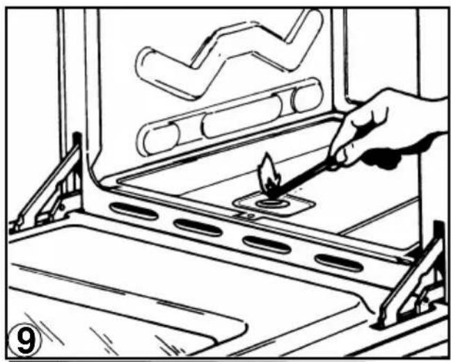
IGNITING THE OVEN BURNER
- Open the oven door;
- press the knob and turn it anti-clockwise to the maximum flame position;
- move a burning match towards the hole in the centre of the oven bottom and press the knob right down (see fig. 9);
- check that the burner has ignited, looking through the hole in the centre of the bottom, keeping the knob pressed all the time;
GB
For the user
- after about 10 seconds, release the knob and check that the burner remains on. Otherwise, repeat the operation.
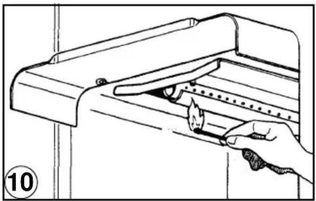
IGNITING THE GRILL BURNER (GAS GRILLS)
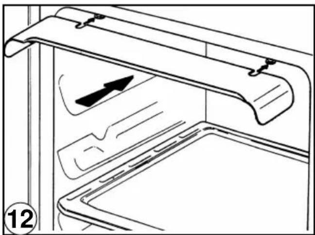
- Fit the control knob guard as shown in fig. 12;
- press the oven knob and turn it to the right until it reaches the stop;
- move a burning match towards the perforated burner pipe and press the knob right down (see fig. 10);
- check that the burner has ignited, keeping the knob pressed down;
- after about 10 seconds, release the knob and check that the burner remains on. Otherwise, repeat the operation.
SAFETY DEVICE
Burners equipped with this device have the advantage that they are protected if they accidentally go out. If this occurs, the supply of gas to the burner concerned is automatically cut off, preventing the hazards deriving from a leak of unburnt gas. The gas supply must be cut off within no more than 60 seconds for the oven and grill burners or 90 seconds for the hob burners.
FOR COOKERS WITH ELECTRIC IGNITION
All the above applies, except that the match is no longer required; a spark is obtained by pressing the button on the control panel once or more, or by pressing the knob of the burner to be ignited.
If electronic ignition is difficult with some types of gas, set the knob on the low (small flame) setting.
- For cookers with electric ignition of the oven and grill burners, ensure the oven door is completely open when these burners are ignited;
- Do not operate the ignition device for more than 10 seconds when igniting the oven and grill burners. If the burner has not lit after
these 10 seconds, stop using the device, leave the door open and wait one minute before trying again to ignite the burner. If the ignition device malfunctions again, light the burner with a match and call the after-sales service.
IMPORTANT
- Difficulty in igniting burners is normal if the cooker has been out of use for some time. The air accumulated in the pipes will be expelled in a few seconds;
- Never allow too much unburnt gas to flow from the burners. If ignition is not achieved within a relatively short time, repeat the procedure after returning the knob to the off position ().
- when the oven and grill are lit for the first time, a smell may be noticed and smoke may come out of the oven. This is because of the surface treatment and oily residues on the burners.
HOW TO USE THE HOB BURNERS
Use pans of diameter suitable for the burner type. The flames must not project beyond the base of the pan. Recommended sizes:
- for auxiliary burners = pans of at least 8 cm
- for semi-rapid burners = pans of at least 14 cm
- for rapid burners = pans of at least 22 cm. N.B.: Never keep the knob at settings between the maximum flame symbol and the off position () .
FOR COOKERS EQUIPPED WITH ELECTRIC HOTPLATES
The different heat settings are obtained as follows:
- 1 = minimum setting for all hotplates;
- 6 = maximum setting for normal and rapid hotplates (with red disc);
-0=off.
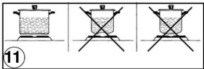
Pans must never be smaller in diameter than the hotplates and their bottoms must be as flat as possible (see fig. 11).
IMPORTANT:
- Never leave hotplates on without pans,
except when first used; leave for about 10 minutes to dry oil or moisture residues;
- if the hotplate is to be out of use for a long time, apply a little grease to its painted surface;
- do not allow spills to burn onto the hotplate, requiring the use of abrasive cleaners.
- After igniting the burner, leave the oven to heat up for about 10 minutes;
- place the food for cooking in an ordinary oven dish and place it on the chrome-plated shelf;
- place the food in the oven, using the shelf on the third pair of runners whenever possible, and turn the knob pointer to the desired setting;
- cooking can be observed through the window in the door with the oven light on. This will avoid opening and closing the door frequently, unless oil or fat has to be added to the dish.
| Thermostat Temperature knob setting in°C | |
| 1 150 | |
| 2 170 | |
| 3 190 | |
| 4 210 | |
| 5 230 | |
| 6 250 | |
| 7 270 | |
IMPORTANT: never place foods directly on the drip tray for cooking; it is there only to collect any drips of fat during grilling.
N.B.: For cookers without thermostat:
with the knob on the maximum setting = 270 degrees C
- with the knob on the minimum setting = 150 degrees C
- All other temperatures between 150 and 270 degrees C are obtained approximately by positioning the knob between the maximum and minimum settings.
Never leave the knob in positions between the maximum symbol and the off setting () .
HOW TO USE THE GAS OR ELECTRIC GRILL
- fit the knob guard (see fig. 12);
- ignite the burner and wait a few minutes to allow it to warm up, or switch on the heating element;
- place the foods on the chrome-plated shelf;
- insert on the highest runner;
- insert the drip tray on the bottom runner;
- gently close the oven door, resting it against the knob guard;
- after a few minutes, turn the food to expose the other side to the infrared radiation (the cooking time depends on the type of food and personal taste).
N.B.: the first time the grill is used smoke will come out of the oven. Before inserting foods for cooking, wait until any oil residues on the burner have completely burnt away.
The grill must only be used at its full rated heat.
IMPORTANT: accessible parts may be hot when the grill is in use! Keep children well away.
The grill element in the top of the oven is switched on by turning the thermostat knob clockwise to the grill symbol on the control panel.
The red light will come on to show the element is in operation.
The table below will serve as a guide; bearing in mind that cooking times and temperatures may vary depending on the type and amount of foods cooked and personal taste.
| Food to be Time (minutes) | ||
| grilled 1st side 2nd | side | |
| Thin pieces of meat | 6 4 | |
| Fairly thick pieces of meat | 8 5 | |
| Thin fish or fish without scale 10 8 | ||
| Fairly thick fish 15 12 | ||
| Sausages 12 10 | ||
| Toasted sandwiches | 5 2 | |
| Small poultry 20 15 | ||
GB
For the user
STATIC ELECTRIC OVEN
- The oven shelf is designed to take normal oven dishes for cooking sweets or roasts, or is used without a pan for cooking foods under the grill.
- The drip tray is only there to collect any juice from foods and must never be used as a cooking surface.
There is a single control knob for the oven or grill.
Starting from the 0 (off) position, the knob can be turned clockwise to the following settings:
- symbol: oven lamp on (it will remain on even if the knob pointer is turned to the other settings).
-
Setting from 1 to 8 (or from 60 to 250 degrees C): oven heat settings, with thermostat control.
-
symbol: grill on (in roof of oven)
- symbol: rotisserie start with grill on.
Turn the knob anti-clockwise to return to the 0 (off) position.
N.B. - The yellow light switches on and off as the thermostat is tripped.
Before placing food inside, allow the oven to heat up for at least 10 minutes.
| Thermostat Temperature knob setting in°C | |
| 1 60 | |
| 2 80 | |
| 3 110 | |
| 4 140 | |
| 5 170 | |
| 6 200 | |
| 7 220 | |
| 8 250 | |
ELECTRIC FAN OVEN
- The oven shelf is designed to take normal oven dishes for cooking sweets or roasts, or is used without a pan for cooking foods under the grill.
- The drip tray is only there to collect any juice from foods and must never be used as a cooking surface.
There is a single control knob for the oven or grill.
Starting from the 0 (off) position, the knob can be turned clockwise to the following settings:
symbol: oven lamp on (it will remain on even if the knob pointer is turned to the other settings) and operation of the fan.
- Setting from 60 to 220 degrees C: oven heat settings, with thermostat control.
symbol:grill on (in roof of oven)
Turn the knob anti-clockwise to return to the 0 (off) position.
N.B. - The yellow light switches on and off as the thermostat is tripped.
Before placing food inside, allow the oven to heat up for at least 10 minutes.
| Thermostat knob setting Temperature in°C |
| 60 |
| 80 |
| 100 |
| 120 |
| 150 |
| 180 |
| 200 |
| 220 |
MULTIFUNCTION ELECTRIC OVEN WITH 4 COOKING PROGRAMS
With different heating elements controlled using a selector switch and regulated by a thermostat, this oven offers various cooking programs. There are three principle sources of heat:
a) Forced heat diffusion (fan oven)
b) Spontaneous heat diffusion (static oven)
c) Infra-red rays (grill)
Starting from the position 0 (off) the selector knob can be turned clockwise to the following positions:
- symbol : oven light and red warning light on
GB
For the user
- symbol or : conventional "static" oven cooking, the oven temperature is controlled using the thermostat knob.
- symbol or cooking with fan oven, on one or two levels, the oven temperature is controlled using the thermostat knob.
- symbol or grill on (on oven top element), the thermostat knob must be set at maximum temperature.
In all positions except zero (0) the red warning light and the oven light are on.
NOTE: The yellow warning light comes on according to thermostat variations. Before putting food in to be cooked, the oven should be pre-heated for at least 10 minutes.
- The oven shelf is designed to take normal oven dishes for cooking sweets or roasts, or is used without a pan for cooking foods under the grill.
- The drip tray is only there to collect any juice from foods and must never be used as a cooking surface.
- Remember that cooking times may vary if food is cooked on two shelves at the same time.
| Thermostat knob setting Temperature in°C |
| 50 |
| 80 |
| 110 |
| 130 |
| 150 |
| 170 |
| 190 |
| 210 |
| 230 |
| 250 |
MULTI-FUNCTION ELECTRIC OVEN
With different heating elements controlled using a selector switch and regulated by a thermostat, this oven offers various cooking methods. There are three principle sources of heat:
a) Forced heat diffusion (fan oven)
b) Spontaneous heat diffusion (static oven)
c) Infra-red rays (grill)
Starting from the position 0 (off) the selector knob can be turned clockwise to the following positions:
symbol or oven light and
red warning light on, operation of fan.
symbol or:conventional
"static" oven cooking, the oven temperature is controlled using the thermostat knob.
- symbol , cooking with
fan oven, on one or two levels, the oven temperature is controlled using the thermostat knob.
symbol , or : grill on (on
oven top element), the thermostat knob must be set at the maximum temperature.
symbol or :intra-red
cooking with fast grill, advised for long grilling: the thermostat knob should be set at the maximum temperature.
symbol , quick cooking
using the fan oven, the oven temperatures correspond to those under the symbol in the table.
symbol or: slow cooking
using fan oven, the oven temperatures correspond to those under the symbol in the table.
In all positions except zero (0) the red warning light and the oven light are on.
NOTE: The yellow warning light comes on according to thermostat variations. Before putting food in to be cooked, the oven should be pre-heated for at least 10 minutes.
- The oven shelf is designed to take normal oven dishes for cooking sweets or roasts, or is used without a pan for cooking foods under the grill.
- The drip tray is only there to collect any juice from foods and must never be used as a cooking surface.
- Remember that cooking times may vary if
GB
For the user
food is cooked on two shelves at the same time.
The table below will serve as a guide, bearing in mind that cooking times and temperatures may vary depending on the type and amount of foods cooked and personal taste.
| Thermostat knob setting Temperature in°C | |
| 60 50 | |
| 80 80 | |
| 110 110 | |
| 140 130 | |
| 170 150 | |
| 200 170 | |
| 220 190 | |
| 250 210 | |
| 230 | |
| 250 | |
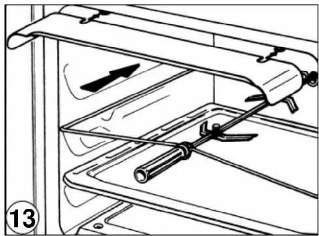
HOW TO USE THE ROTISSERIE
- fit the control knob guard as shown in figure 13.
- ignite the grill burner, or switch on the grill element;
- impale the meat for cooking on the spit and fix it in the centre of the two forks;
- insert the end of the spit into the motor drive socket;
- remove the handle from the spit;
- place the drip tray on the bottom runner of the oven;
- gently close the oven door, resting it against the knob guard;
- start the rotisserie motor by pressing the switch on the symbol.
- baste the meat from time to time. When cooked, screw the handle onto the spit and remove from the motor drive socket.
OVENS WITH THERMOSTAT
If cooking temperatures are not as set, call in an engineer to check the thermostat.
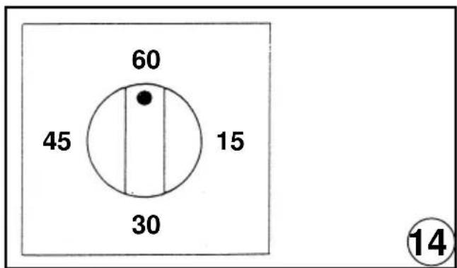
HOW TO USE THE MINUTE MINDER (Fig. 14)
Set the cooking time considered necessary by turning the timer knob clockwise. An alarm will sound at the end of the preset time.
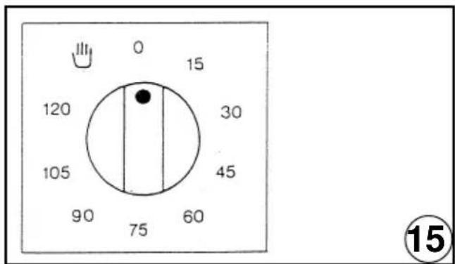
USE OF SINGLE-CONTROL END OF COOKING TIMER (WITHOUT CLOCK) (fig. 15)
This allows the cooking time to be programmed.
Operation:
- Move the knob to the desired cooking time (120 mins max. for the electric oven; 100 mins max. for the gas oven).
- Choose the temperature using the thermostat knob and move the selector knob to the required cooking method.
- When the programming knob is at the 0 position the oven will switch itself off. This is automatic.
- Move the thermostat knob back to symbol
- Move the selector knob to symbol 0.
N.B. If the timer is not used, the oven programming knob is to be set to the manual position
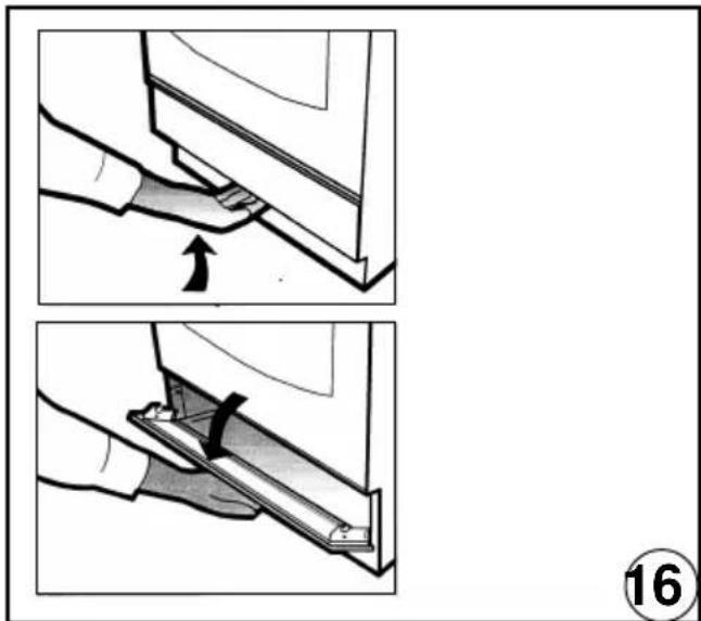
WARMING COMPARTMENT
To open the warming compartment, open the flap door with one hand (see figure 15).
To close the warming compartment, simply press the flap door back into place.
GENERAL PRECAUTIONS
- Always disconnect the power supply before any work inside the oven or where live parts may be accessed.
- Never use the warming compartment for storing inflammable liquids or items which do not withstand heat, such as wood, paper, aerosol cans, matches, etc.
- Make frequent checks on the rubber connection hose, ensuring that it is well away from hot surfaces, that there are no sharp bends or kinks, and that it is in good condition. The hose must be replaced at the latest at the indicated date and must be se
GB
cured at both ends using a standard hose clamp.
- If taps become stiff to operate over time, contact the After-Sales service.
- Wash enamelled or chrome-plated parts with soapy lukewarm water or non-abrasive detergents. A metal brush may be used to remove deposits from hob burners and flame caps. Dry thoroughly.
- Never use abrasives to clean enamelled or chrome-plated parts.
- Do not use too much water when washing the hob. Take care that no water or other substances enter the burner housing holes, as this may be dangerous.
- The spark plugs for electric ignition must be kept clean and dry; always check after use, particularly if there have been drips or overflows from pans.
- Never close glass lids until the hob burners or hotplates have cooled completely; it might shatter or crack.
- Never knock enamelled parts or ignition spark plugs (where present).
- The main or wall gas tap should be turned off when the cooker is not in use.
- Never lift the cooker by taking hold of the oven door handle.
No liability is accepted for injury or damage caused by poor installation or improper use of the cooker.
In case of malfunctions, particularly gas leaks or short-circuits, contact your engineer without delay.
RU
CoepeKaHne
TexHHueckne daHHbIe H
XapakTepeHCTNKN 40
YcTaHOBka 41-44
BeHTnJIaIeH IOMeIeHHN 41
Pa3MeIeHHe 41
IopKJIoueHne Kra3OpacPpeJeJIHTeJIbHOI ceTH 41
Hactpoika Ha
pa3JIHnHbI TnIbI r3a 42
3aMeHa KHKJepOB 42
PerylnpoBka IOnaUn BO3dyxa 42
PerylnpoBka
MHHMaJIbHOTo IJaMeHn 42
IIOKJIIOUeHHe K 3JIeKTPoCeTn 43
3JIeKTpNueeCKoe 3aXnraHHe 44
PpeOxpaHHTeJIbHOe Ra3OKOHtPOJbHOe
ycTPOIcTBO 44
HΦOpMaunIaI
noTpe6nteJIe 45-52
BeHTnJIaIeI NOMeIeHnI 45
3aKnHaHne ropeJIOK 45
BkJIoueHHe Ra3OBOn IyXOBKn 45
BkIoueHne r3oBOrO rpiJ 45
PpeoxpaHnteJbHoe
ycTPOIcTBo Ra3OKOHpOJIa 45
3JIeKTpHueeCKoe 3aXnHaHHe 46
HcnoJb3OBaHHe Ra3OBbIX TopeJIOK
paobouenIOBepxHocTHIJIHTbI 46
HcnoJb3OBaHHe
3JIeKTpHueccknx KOHΦOpok 46
HcnoJb3OBaHne ra3OBOI dyXOBKn 47
HcnoJb3ObaHne r3OBORo
HIN 3JIeKTPnuecKO rpnJr 47
HcnoJIb3OBaHne KOHBeKUHOHHoH
3JIeKTpHueeCKoI dyXOBKn 48
HcnoJb3ObaHne 3JIeKtpnueckoI
IyXOBKN C CHCTeMOB BeHTHJIaUN 48
HcnoJIb3OBaHHe 3JIeKTpHuYeCKoI
KOMHHPOBaHHOH JYXOBKN 49
HcnoJb3ObaHne 3JIeKtpnuecko
MHOROΦyHKUHOHaJIbHOJdyXOBKN 49
HcnoJb3OBaHneBepTeJa 50
DyXOBKn C TePMOpeYJITOpOM 51
HcnoJb3ObaHne TaIMepa 51
HcnoJb3ObaHne nporpaMMpyuioero
ycTpoHCTBa 6e3 yacOB 51
OTdJIeHne pa30rpeBa TapeJIOK 51
PekomehdaaHHIO
TexHHKe 6e3OpaHocTH 51
PncyHKn 93-95
JepXaHNCCTUJIeHneI
- Ha7a Фнрma ьаогадapnt Bac 3a Bb6op H NOKyNk OdHOrO H3 Ha7nx BBICOKOKaueCTBHeHbIX n3deJIn. Mbl Tropya HoHaJeEMcra, yTO B BaIHX pyKax Ha7n PJIHTbI 6ydyT fYHKUHOHPoBaTb C MaKCHMaJIbHOIOTdaeH HAnLYu7HMn pe3yJbTaTaMH, OIIpaBdbBa8 BCE BaIIN OxHJaHn. C 3ToI IeJIbIO ppeJIraeM Bam BHIMaTeJIbHO IIPOHTaTB HAcTOJWee pyKOBoDCTBO H IIpHIDepXHBaTbc8 Tex eRO yKa3aHH, rIpepehIeT O pHi6Opax n CnCTeMax, KOTOpBMN OChASeHa Ba7a PJIHTa. FApRkaFap - H3ROTOBNTeJIb CHHMaet C c68 BCaKyIO-H3I OTBeTCTBeHHocTb 3a IOBpeJDeHn,OTBe HeHCnPaBHOCTHn HecuaCTHbIe CJyuAn,HeNC BBi3BaHHbIe HecO6JIIODeHnEm peKOMeHdaUHNBBi3Ba IIO YCTAHOBKE IN 3KCNJIyatauH IN JIHTbI.No yCTaH
-ДЯTORO,YTO6bl BblnyckaTb ПЛNTbl B COOTBETCTBHN C COBpeMeHHbIMN TEXHOJIOrHuYeCKHM peSeHnMaH N/HJN DJIЯ NOCTOARHHORIO NobIeHnKaueCTBa HauHX H3deJIn,Φa6pHKa OCTaBJeT 3a CO6oI IpaBO BHeCEHn KaKHX-JH60 N3MeHeHn Jdaxe 6e3 PpeBapHTeJbHOrO PpeDynpEjKeHn,UTo,ODHaKO,He BB3bIBaEt PpO6JIem HJN 3aTpPydHeHn Prn 3KcPJIyaTaun.
- EcJH BO3HNKHeT HeoXOdHMocTb 3aKa3a 3anacte, Hado cdeJaTb 3anpoc BaWemy npOabuy, rde cJeDeyET yka3aTb Homep MOeJIH HOMep cepHHI INHTbl, «PPOHTaMnOBaHHbIe Ha φa6pHuHO ON03HaBaTeJbHO TaJIHKe. 3Ta TaJIHka MoKeT 6bITb pacIOJIOKeHa BHyTpN OTJeJIeHn pa3OrpeBa TaPeJIOk (ecJH ecTb) JIN Ha 3aADHe CTOpOHe IINTbl.
-ПЛИТа COOTBETCTBYeT HOPMaTHBaM;
-
CEE 90/396
-
CEE 73/23 n 93/68
-CEE89/336 (no ypoBHOpaHIOHOMex)
-CEE 89/109 (KoHTaKTnpoBaHne c HIIeBbIMN PPOyKTaM)
IIOYCHEHNE
-BHaCTOJHcEMpyKOBODCTBe npedCTaBJIaIOT HHTepec ToIbKO Te naparpaΦbl NIN pa3deJIbl, rIe roBOpHTbcra O npnbopax, KOToPbIMN OChAueHa Baasa nIHTa.
RU TexHnueckne daHHbIe H XapaKTePnCTNKN
0145 1,0 KBT - ObbyHaЯ KoHΦopKa
1,5 KBT - bICTpaKa KOHΦopKa
0 180 1,5 KBT - O6bUHaJ KOHΦopKa
2,0 KBT - BbICTpaKa KOHΦopKa
MOUHOCTH 3JIEMEHTOB
coPOTnBJIeHHe IoJa 1,5 KBT
CONPOTNBJIeHHe CBOda 0,7 KBT
KpyroBoe cOnpoTnBJIeHHe dYXOBKn 2,0 KBT
B uactHOCTH, KOJIuYeCTBO CBExKeRO BO3dyxa, Heo6xOJHMOrO IJIa RopeHHra3a, OJXHo 6bITb He MeHbIe, Yem 2 M3/uaC Ha KaXdbI KBT HOMHaJIbHOYcTaHOBJeHHo MOUHOCTH.
BJIIO6OMcIyuaeHaCToTeJIbHOpeKOMeHdyeTcNcNoJIb3OBAtMyΦTy.
-CoeHHeHcpe3nHObblmIHaHromHaWtUepeCoed (cmOTpn pnc.3CnD)
CoeHHeHne BbINOJHaeTc npn NOMOupe3NHOBOrO 7IaHra, MapKa KOTOPOROCOOTBcTByET DeiCTBYIOUHM HaUNOHJIbHBIMCTaHdApTaM. O6a KOHua 7IaHra DOJXHbI 6bITb3aKpeIIeHbI cTaHdApTHbIM 3axmAMn.Heo6xOIMO npOn3BOIDtB 3amEny 7IaHra BycTAHOBLeHHbI CpOK I DOCTyn K HEmy DOJXeHN D0C6bITb 06JIeYeh dJIa KOHTPOJIg ETOOCTOAHIN IO6bITbBCeI DnHE.BCe IINIHe.
BHIMAHHE:BHMMAHNE:
-IVcnoIb3OBAHHe wTyuepa Donyckaetc TOnbko- Hcnn dIa camocToTeIbHOYCTAHOBKn. B cnyae,dlra 0eJn IInTa YCTAHABINBAeTcM EMy DByMmGcn 3JeMeHTamn Me6nn KnaCCa 2 st. 2-1, ToJne
Donyckaetcra Nlub TOnbKO XecTKOE COeHHeHne.DonyckaemepdNlb TOnbKO XecTKOE CoeHHeHne.
BHIMAHHE:BHIMAHHE:
-0000 100KIOOeyHnI NNTbl
KnOcne PpeBapHnBHO KpeIeBBnH.
mora3opacneTeneHoCetn Heo6xmo
SaMeHTb KKnKJIep NCHTOE3Vr TOpueBOH
n.npoBepntBa3OHpOHnAeMOCTcOeONHn.
TpyoaTBn KJIIOpa3MePOM /MM.
ra3opacnpdeJeNTeJbHOcTeHneO6xOaUMora3OpaeJeNTeJbHOcTeHneO6xOaMnO
PPOBepNTb ra30HeNpOHnUcaEMoCTb COeHNHeHn.PPOBepNTb Ra30HeNpOHnUcaEMoCTb COeHNHeHn. TpyoQaTbKJIou pa3MePOM/ MM
-ДяфункungоноваяплntынБутанe/Пponане Heo6xOДМо y6eДNTbCЯТо Давлиенe ra3a cETN COOTBeTCTByET DAblenHIO, yka3aHHOMy Ha ФабрчHО onO3HaBaTeNbHOn Ta6nUKe.
- IcnoIb3OBAbToJIbKO cTaNapThbIe pe3HOBbIe ⅢaHr. Pn pa6oTe Ha cKJXKeHHOM HePfTahom Ra3y IcNoJIb3OBAbT b JlaHr, COOTBeTCTByIOuIM DeIcTBYIOUIM HaIOHOHaNbHbIM CTAHdApTaM.
-36eRaTb CnIbHbIX N3rN6OB H nepeXaTNI Tpy6bl NN IJIaHaR a n CTapaTBcA He npCNoHra TB erO K pa3OrPeTbIM CTEHKAM PNTbl.
- CoeINHeHne paAMnbl COOTBeTCTByeT HOpMaM ISO 228-1.
3AMEHA JHKJIEPOB TOPEJIKN PRHJIa (pnc.6)3AMEHA
- CHHMMTe TopeJky, PpeBapHTeJbHOOTKpyTNB Dba KpeIaune ee BnHTa
-3aMeHHTe KHKJIep, HcIOJIb3yJr TOPueBOH Tpy6aTbI KJIou Ha 7 MM.
PEKOMEHDAUHNEPEKOMEHDAUH
-Пи yctaHOBKe JHKJIePOB HNKoIgda H3JINHHe He 3aTЯHbAHTe HX KJIHOYOM
-ПослеЗamehbI BcexЖнКлерOB ПpoBepbTe INXra3OHeHpOHnUcaEMoCTb.
PEYJINPOBKAIIOAUNBO3DUXATOPEJKAMPERYJINP
HACTPOHKA HA PA3JIINHbIE TINbI FA3AHACTPO B clyuae, ecn HcnoJb3yeMbn DJIa FyHKUHOHPOBAHNAI IINTbI Ra3 OTJNUaETcR OYka3aHHoro, HeoXoIMHOACPTpOHT bIHTy, DeiCTByr CJeDyUHMM Obpa3OM:
-3aMeHHTb XHKJIepbl (B COOTBeTCTBHN C Ta6JIHcEHa cTpaHHc 34).
- BbIIOJIHHtB peRyJInpOBky IOnaun BO3Iyxa.
- BbIOJIHHTb peRyJINPOBky MHHMaJIbHOrO IIaMeHN BCex RopeJIOK.
IpiMeaHHe:PiN KaXDoI CMeHe Ra3a HaKJEnBaTb HaΦaOpHuYO Ta6JInuKy Ha3BaHHe HOBOrToHnPa Ra3a,Ha KOTOpBII HAcTPOeHa PJIHTa.
BHHMaTeJIbHO DaccMOTpHHe HxKeIPOBHeEHHyIO
Pika HA PA3JINuHbIE TINbI I A3A TaJIuCy (OpeHTnPoBOUHbIe DaHHbIe) JJIa peYJInpOBAHnnaPapMeTpa H, BblpaKeHHO BMM., Ha pnc. 4 JJIpaBoueH IOBepXHOCTN JIHTbI, Ha pnc. 6 JJIra rPiJIa.
PPOBepntb yHKUHOHPOBaHne RopeJok
3AMEHA JHKJIEPA FOPEJKN DYXOBKN (pnc.3AM 5)
-OTBnHTb BNHT, KpeIaH NHO yXOBKn.
- CHaTb dHO dYXOBKn (npoDbHHyB ero
AOPAOKAQHJIRBERYXOSEN
B cIyuae, ecJn nIHTa yHKUHOHpyeT Ha CxHXKeHHOM r3e (D/II), peryIInpoUhbl BnHT DoJIkeH 6bITb 3akpyueH Do yNopa.
RU
YCTAHOBKA.
JIHTa MoKeT 6bITb OCHaSeHa KpaHaMn TnPa
A》,cYCTaHOBJIeHHbIM BHyTpHpeRyJInPOBOUHbIM
BHTOM(peRyJInPOBaTb KOtOpbIM MOXHO IIpH
IOMOUI MaJIeHbKOI OTBePfKU Hepe3
CTepKeHb)IIH TNpa《B》C HApxHbIM
peRyJInPOBOUHbIM BHTOM C IpaBOI CTOpOHbl
(eRO MOxHO peRyJInPOBaTb HeIOcpeIcTBeHHO),
CMOTPN pnc.7.
EcnIyHKnHPOBaHHNJIHTbI HcNOJb3yeTcHaTypaJIbHbI Ra3,TO He3aBHCMOOTTHPaKpaHaJeCTBOBaTb CJeDyIOIMO6pa3OM:
3aXrnte ropeJky yctahOBHTe MaKcHMaJIbHOe IJaMa.
- CHHMTe pyky peryIaTopa, noTaNHyB ee Ha ce6, He HaxHMa Ha nepeDnIO nAHeJIb PINTb BO N36exaHHe ee NOBpeXDeHn.
-ПрнпомоиmaJIeHbKOI OTBepTKN OTKpyTHTe peRyJInpOBOuHb BnHT np6JIN3HTeJbHOHa TPh O6Opota(BpaaJa OTBepTKyIpOTNBacOBOnCTpeJKN).
-Повернеле се pa3 cTepeKeHb КраHa ПpoTHB Yacobои CTpeJKN Do eRo 6JIOKINPOBKN. B 3TOM CJIyuae 6yIeT MaKcHMaJIbHOe PJIaMЯ.
- OueHb MeIeHHO 3aKpyTHTpepyJInpOBOuHbI BnHT, He HaXHMaHa OTBepTKy, Do Tex NOp, Ioka IIaMRe He yMeHbIHNTcR Ha 3/4. PnI 3TOM ObpaHTe OCOboe BHMaHHe Ha To, YTO6bl IIaMRe 6blIO DOCTaTOUHO yCToIuHBbIM DaKe Iprn yMepeHHOM INOTKe BO3dYxa.
TePMOpErJyIaTopaHnKpaHa(pHC.8)
- OTKpyTHTe peRyJInpOBOuHbI BnHT np6Jln3HTeJIbHo Ha Tprn o6Opota.
-Yepe3 5-6 MHHyT yCTaHOBHTe yKa3aTeJb pyuKN B NOJIOKeHHe MHHMaJIbHOrO IIJaMeHN.
MeJIeHHO 3aKpyTHTe peRyJnHPOBOUHbI BnHT,Ha6JIIOJaYMeHbIIeHHe IJIaMeHN uepe3 CTekJIO B DBePue DyXOBKn (DBePua 3aKpbITa) Do Tex IOp, IOKa KOHyc IIaMeHN He yMeHbIHTcA Do 4 MM. PnH6JIH3NTeJIbHO. He peKOMeHdyeTcA CInIKOM yMeHbIaTb IJIaM. OHO DOJIxHO 6blTB CTA6NJbHbIM DaJKe Ipn 6bICTpOM OTKpbIBaHHN 3aKpbIBaHHN DBePbI DYXOBKN. - BbIKJIIOUHTe IopeJky uYcTaHOBHTe dHO DyXOBKn Ha MeCTO.
IOKJIIOUeHNEK 3JIeKTPOCETNIODKJIIOUeHNE K
IpeXdyeem NOdkJIOUaTb JHTy K 3JIeKTPocetH, Heo6xOdIMO y6eHNtbcra, YTO:
HaIIpIeHHe BHeIeHcETn COOTBeTCTByeT NaPaMeTpam, yKa3aHHbIM Ha a6pHuHO OIO3HaBaTeJIbHO TaJNuKe
-po3eTka 3a3eMJIeHnI yHKUHOHpyeTe EcIn po3eTKa IJIy IIOKJIuOeHnI IJIHTbI paCNOJIOXeHa B TpyDIOHOCTYINOM MeCTe, HalaJyNK DoJIKeH IpeDyCMOTpeTB BbIKIOUaTeJIb C 3a3OpOM pa3MbikHnI KOHTaKTOB paHBIM IJIH IpeBbIIaIOUHM 3 MM. EcIn IIHTa yKOMJIeKTOBaHa ceTeBBIM IHyPOM 6e3 BNIKN, TO IJIy IIOKJIIOUeHnI
PEYJINPOBKA MHHMAJIbHOI OIIAMEHHPEYNIRRBAKAcMnHBMAtbHoTApAMyEHBNky.
TOPEJKN DYXOBKNFOPEJIKN DYXOBKN IIpn 3TOM Heo6xOIMo yuHTbBaTb
B cIyue, ecJIn PJIHTa FyHKUOHNPyET Ha cJeDyIOOE:
- JKeJITo-3eJIeHbI IPOBOI DOLJKeH HcIOJIb3OBaTbCra ⅡJIa 3a3eMJIeHHA
TJyboI npBOI IJIa HeITpaJIH - KOPHHeBbI PNOBOd IJa HaPpJKeHnCeTH
- HHyp He DoJKeH COpnKacatbCn CoCTeHKaMn PJIHTbl, HarpeBaIOUHMnCn 6OJee 75^
- B Cnyuae 3aMeHbI ceTeBOrO uHypa HcNoJb3OBaTb uHyp Tnna HO5RR-F HnH HO5V2V2-F IOnxOJaero ceueHnA (CMOTPH CXeMbI Ha pnc. 2).
-ecJINIJIHTaIOCTaBJIeHa6e3ceTeBOrO
Hypa,PINIOJIKJIIOUeHHNHCNOJb3OBaTb
HypTNIIaHO5RR-FHNHO5V2V2-F
CKNKHeHHOMra3e(/II),peyJInpoUHbIN BnHT DOJIKeH 6blTb 3akpyueH Do yIopa.
EcnI JIyHKUHPOBaHHIJIHTbI HcNOJb3yeTcHaTpyaJIbHbIra3,TO He3aBnCHMOOTTHaKpaHapeRyJnPOBKa MHHMaJIbHOIJaMeHH BblIOJHAreTCs CJIeDyUOIM O6pa3OM:
- CHaTb DHO DyXOBKn (UTo6bI BbHyTb DHO, HEOOxMO OTBnHTnTb BNHT).
-3aKHTe ropeJky dYXOBKn H yCTaHOBHTe yKa3aTeJIb peRyJInpOBOuHOn pyuKn B NOJOxKeHHe MaKCHMaJIbHOrO IJaMeHN.
-3aKpOHTe DBepUy DyXOBKn.
HaIInTe peRyJINPOBOUHbI BnHT
RU
YCTAHOBKA
NODXODJaero CeueHna (CMOTPN CXEmbHa pnc.2).
BHIMAHHE:BHIMAHHE:
IPOH3BOIDTeJIb He HecET OTBeTCTBcHHOCTH 3a IOBpeJdeHnR, Bbl3BaHHbIe HecO6JIHODeHnEM BblEuyKa3aHHbIX Tpe6OBaHn I DeIcTByIOuHX IpaBnI NO TexHnke 6e3oNaChocTH nPn IPOKJIUoyEHn IIHTbl. O6raTeJIbHo IPOBepbTe, YTO IPOBOd 3a3eMJIeHnR IIHTbl IpaBnJIbHO COeIHHeH C CeTbIO 3a3eMJIeHnR (CMOTPN CXEmbHa pnc.2).
- Upe3 90 cekyH B clyuae KOHTpOJIra ropeIOK pa6oueH IOBepxHocTHn Upe3 60 cekyH B clyuae IopeJIOK dYXOBKN IprNJI IOBepHyTb pykU B NOJOKeHne «OTKpbITO».
- OctabbTe pyky B 3TOM IOJIOKeHHN H np6Jn3HTb 3aXKeHHyIO CCINuKy K ropeJIke: FOPEJKA HE DOJIKH A XKEUbCra. Bo BpeM 3aXnHaHn Tpe6yOTc nPn6Jn3HtEJIbHo 10 ceKyHd dIЯ BO36yKdEHn MaHHTa.
KJanaHra3OKOHpOJIcpaTaBBAeT aBTOMaTHueCKNIOcJIe BbIKIQUeHHIJIaMeHH
JIHTbl, OCHAUHbIE CNTTEMOJ3JEKTP03AXHNAGHHN3JEKTP03AXHNAGHHTouHbIe paCCTOHm MeKdy 3JEKTPoDm IropeIKoYka3aHbHa pnc.4,5,6.
EcHn HcKpa He Bb6HbAeTc, He yOpctBynte, T. K. MoXHo IOBpeNTb rHepePtoP. CnCTema 3aXnraHnMoXeT He cpaTaBbAtb NcJeDyUOuM pNCHHaM:
-BJIaXHa,HeICpBaHHaIIN3aFpy3HeHHa CBeua.
-HeIpaBnJbHo ycTaHO bJeHO pacCToHHe MeKdy 3JIeKTPODOM H RopeJkoH.
TOKOINPOBOJIAHNI INPOBOIDOK CBEHNIOBpejKeH HJN OTOJIeH.
- NCKPOBOI pa3pIyXOHTB 3eMJIIO (B)pyrHx YacTEx IJNTbI).
- IOBpeKdE H rHehepaTOp MKNPOBblKJIIOuAteJb.
- cKoJIeHHe BO3dUxa B Tpy6OpPoB0dx (OCO6eHHo NocJe JInTeJbHOro nepHOda HEnCIOJb3OBaHHra IIHTbl).
- HenpaBnJbHo COCTaBJHeHa Ra3OBO3dYuHna CMeCb (HenpaBnJbHoe TopeHne)
HbI6oJeOCHA HepEeCEkyCJTeMropeJOK paobouen NOBepxHocTN PnHTbN uepe3 60 CEkyHd IJIra RopeJOK DyXOBKN rpnJIA
HJH YcTaHaBJIbBa Ha MeCTO pa6Ouyo IOBepXHOCTb IInTbI y6eINTEcB, TTO 3JIeKTPnueCKHe PPOBOdkn CBeueE (ecJH HMeOTc) He COpPrkacAOToC XHKJIepaMn H He NepeKePbIBaIOT HX.
IPEIOXPAHHTeJIbHOE YCTPOINCTBOIPPEIOXPAHHTeJIbHOE YCTPOINCTBO I3OKOHPTOJIIA3OKOHPTOJIIA
IpaBnJIbHOe paCCToHHe MeKdy KOHcAMN UyBCTBHTeJIbHOrO 3JIeMeHtA TePMOnapbl H RopeJIKOJ NOKa3aHO Ha PNC.4,5,6. IJIaKHTPOJIaYHKUHOHpOBaHHa KJIaHaHa Ra3OKOHPToJIa DeHCTBOBaTb CJeDyUHIM O6pa3OM:
- 3aJrnte ropeIky H octaBbTe ee BkJIIOUeHHo INpN6JIH3NTeJIbHO Ha 3 MmHyTbI.
- BbIKJIOHTe rOpeJIky H NOBepHHTe pyUKy peRyJIaTOpa B NIOJIOKeHHe 3aKpblTO》, 0603HaueHHoe cHMBOJlOM ().
RU HHΦOPMALIJI JIOTPENEJIEN
KAK HCIOJIb3OBATb IIHTYKAK HcIOJIb3OBATb HHTYKAK Ha pyUky H NOBepHnTe ee npOTHB acobO B CTpeJKN DO NOLoJKeHn
BEHTNJIAIINI IOMEIIEHHBEBTHJIAIINI IOMEIIEHKCHMaJIbHOIJIaMeHN.
3KcJIyaTaunra3OBOI INHTbICOPPOBQJaETCBbldeJIeHHeM TeIIObI N BlaJXHOCTNBIIOMeHNN,Γe OHa yCTaHOBJIeHa.10TOMy,HEoBXoJIMo 06ecIeHuTB BeHTNJAICIINIOmeIeHHN I NOIDepKHBaTb OTKpbITbIMNECTeCTBeHHbIE BEHTNJAUNOHHbIE OTBepCTNHNJYCTaHOBTb BBITJXHOH 3OHT.
BcIyuae IJIHTeJIbHO r HHTeHCHBHOrO HCIOJIb3OBaHHr PJIITbI BO3HNKaet HeoXoJIMOCtB DOIOJIHHTeJIbHOI BEHTNJLrN, KaK, HaIPMHep, OTKpbITb OKHO JIN yBeJIuHTb MOIHOCtB BbIHxJDeHHOI BEHTNJLrN IN BBITXHO r 3OHtA.
- 3aTeM NOdHeCHTe 3aKkeHHyU cNnUky K UeHTpaJIbHOMy OTBepCTnIO Ha IHe dYXOBKN H NaKMITE Ha pyuKy Do yIopap (CMOTpn PnC.9).
-He OTnycka pyuKn y6eHntecb B TOM, YTO TopeJIka 3aXgIacb, H6JIIOaI IJaMaY uepe3 IeHTpaJIbHOe OTBepCTne Ha dHe dYXOBKn - Pn6JH3nteJIbHo uepe3 10 cekyHd OTnyCTHTe pyuKu I npOBepbTe, He NotyxJa JI H ropeJIka. B IpOTNBHom clyuae NOBTOpHTb BCE cHaJa.
BKJIIOUOHEHNE FOPEJIKN IPRJIA(A3OBbIBBKMJI HPNJIb)IPINJb)
BKJIIOUeyHNE I OPEJIOK PABOUEBKBJIIOUYEHNEHOBHTOPEIIOKaHky PAIOOHEaunTbI IOBEEPXHOCTN IIINTBIIIOBEPXHOCTN IIINTbl peyJInpOBOuHbIXpyeKOT NOTOka
- HaKMHTe H NOBepHHTe peRyJnHPOBOUHyIO pyuKy IpOTNB YacOBON CTpeJKN UcTaHOBHTb OTMeTKy HaIpOTNB CUMBOJa 06O3HaueHHORo Ha IpeEHN PaHeJN PJIHTbl (NOJOxKeHne MaKcMaJIbHORO PJIaMeHN).
- 3aTeM NOdHeCHTe 3aXKeHHyU cINuKy K TopeJIke.
-ДяуMeHbIeHnIJaMeHnIOBopaHBaIte pyky B TOM Ke HaIpaBJIeHN, yCTaHaBJIbAOTMeTKy HApPTHB CHMBOJa (IOJOKeHne MHHMaJIbHOrO IJaMeHN).
TROPaTeBO3dyxa,KaKya3aHOHaPnC.12. HaXmIteHapeRyJInpOBOuHyOpyuKy dyXOBKnHIOBepHnte ee BnPaBOIO KOHua.
- 3aTeM NOIHeCHTe 3aKKeHHyU cNHyK K nepΦopHPOBaHHo Tpye TpeJKN HaxMMTe Ha pyuKy Do yNopa (CMOTpn PnC. 10).
-He otnyckay pyuky ybeintecb, uTo ropejka 3aXrJacb.
-ПибЛиЗnteЛьно uepe3 10 cekyнд OTПуСТИЕ рУЧКИ YБЕДИТЕСВ,чTO rOpeJIka HeNotyxлa.ВпOTиВHOM cIyuae
BKJIIOUeHNE TOPEJOK PAOueHBKJIIOUeHNE TOPEJOK PAOueH NIOBEPXHOCTN, OCHAIIEHHbIX KJIAPAHOMIOBEPXHOCTN, OCHAIIIEHHbIX KJIAPAHOM IPIEDOXPAHNTIELbHOE YCTPOHC
HaKMHTe HIOBepHHTe peTyJINpOBOUHyO pyuKy IpoTnB YacOBOn CTpeJKN UyCTaHOBHTe OTMeTKy HaIPOTHB CmBOJa 06o3HaueHHOrO Ha IpeEHei NaHeJN IIJTbI (NoJIOXeHne MaKcHMajbHOrO PJIaMeHN).
- 3aTeM NOHeCHTe 3aXKeHHyU cHNUky K TOpEJIke HnKaMTe Ha pyKU Do yNopa N DePKeIte ee npJkaToB B TeueHn Pn6JIn3HTeJIbHo 10 ceKyHd.
- OTnycntte pyuky n y6eHNTecb, YTO ropeJka 3aXrIacb. B npOTnBHom cIyuae NOBtOpHTe BCE cHaaya.
A3OKOHPOJI A3OKOHPOJI
IpeHMyueCTBO OchaueHHbIX 3TUM
yCTPOIcTBOM IopeJIOK COCTOHT B TOM, YTO B
Clyuae HeIPOH3BOJbHOr RaIIeHnIaMeHN
CpaBaTbIBaET CNTeMa 3aIITbI. DeIcTBHTeJIbHO,
B 3TOM Clyuae aBTOMaTHueCKN PpeKpaIaetcR
NoJaHa ra3a K NOTyXWeI RopeJIke, No3BOJra
TaKHM Obpa3OM H36ExaTb ONacHOCTN yTeKN
ra3a. NocJe HeIPOH3BOJbHOr RaIeHnI
JIaMeHN KlaIaNr Ra3OKOHPOJIa cpaBaTbIBaET
aBTOMaTHueCKn He 6oJIee Yem uepe3 90
CEkyHd IJIra RoPeJIOk paBoUey IOBepxHOCTN
JIHTbI N Uepe3 60 CEkyHd IJIra RopeJIOK
DyXOBKn H rPJIJI.
BKJIIOUeyHNE IOPEJKN DYXOBKNBKBJIIOUeyHNE IOPEJKN DYXOBKN
-OTKPOITe DBePuy dyXOBKN
RU HHΦOPMAUЯДЯ NOTPEBNTEJIEN
IJIHTbl, OCHAUEHHbIE CNTTEMOIIJITMacIAOeMaHErpeKTEMOJ 3AJNFGAHNOIOT3JEKTPNUECKON NCKPbI3AJNFGAHNOIOT3JEKTPNUECKON NCKPbI
PnHnH 3aKHaHn TaKo KcKaONHcHO BbIe, 3a NCKJIHueHem TOrO, YTO BMeCTO CnUck HcNoJb3yeTcR NCKpa, NOJyAema np HaJatn, DaJce MHOrOKpaTHOM, paNIOJIOJKeHHo Ha IpeDHe N aHeJN KHOJKN, HJN JKe HaxHMaj Ha pyKoTky RopeJKN, KOtOpAra DOJXHa 6bITb BKJIOUeHa. B cLyuae, ecIn ropeJka He 3aXHraTeCra, IoppoBoBaTB eIe pa3, yCTaHOBnB peryJInpOBOuHyO pUky B NoJIOJKeHne MNHHMaJIbHOrO PJIaMeHN ().
HcIOJIb3OBAHNE KOHΦOPOK ΓA3OBONCIOJIb IINTblIITbl
HcnoJb3yIte KacTpOJIc DnHaMeTpOM dHa, IOxOJaIeRO K DaHHOMy pa3Mepy KOHOpKn. IJaM He IoJIxHO BbIPbBaTbcra N3 IOKacTpOJI.N PekOMeHdyeTc:
-ДЯ MaJIoI IopeJIKN HcIOJIb3OBaTb KaCTpIOJIN DHaMeTpOM 8 cm.
-ДЯсpeДнHeIROpeJKNHcIOJb3OBaTb KaCTpOJIINdHaMeTpOM14cm.
-ДябOЛьшОI ГорЕЛКИнспОЛьЗOBaТb
-EcIn nIInTa OcHauneHa cHCTeMOEcn KaIIpHAn DaaMeIpeHa22 CMCTeMoN 3JIeKTPo3aXnraHn rOpEIOK IyXOBKn HJIeK TPOBbAaHn HIOxPeJIOKHeYXoABHBnBaHTe RPNIA, pIN INX BKLIOUeHN NOpHTePNOBBAHOHOMeKyTOHoe IOJIOKeHne Mekdy DepeKaTb DBepu y DyXOBKn POJIHOCTbIODepeKaTb MaKyMaBbHOToHpaTeHn H OTKpbIToN.OTKpbIToN. IOJOOKeHnEM 3aKDyBaHn ()
-BoBpEmBAJIIOeHnI RopeJIOK LyXOBKn HrPnJI, OCHaUeHHbIX CnCTeMOJ 3JIeKTPO3aXnHaHn, He HaXmIte Ha KHOIIy 3aXnHaHn 6OJIee Yem Ha 10 cKeYHd. EcJN Upe3 10 cKeYHd RopeJka He 3aXkTeTc, OTNyCTHTe KHOIIky, OTKpoITe DBepCy DlXOBKn I NOoXdHTe NOKpaHHe Mepe MHNHY TnpEx De Yem IOBTOpHTb BKJIIOueHHe. EcJN Xe RopeJka He BKLIOuaETcN O npuHHe HenCnpaBHOCTn CnCTeMbI 3JIeKTPO3aXnHaHn, To 3aXnTe RopeJky BpyHyIO pHi NOMOUn CnNUCKn, a 3aTeM BbI3OBHTe CneUaJIHCTa NTo TEXO6CJyXHBHIO.
PpeDyIpyEeHHeNpEeDyIpyEeHHe
-06bIuHOIOcJIe IJIHTeJIbHOrEOHcNOJb3OBAHHaIIHTbI cpa3y He ydaetcraKechropeJIKn. PepeI 3aXnHaHem IOCTaTOUHO IOIOxJaTaHeCKoJbKOceKHyD, NOKa He BblDeT CKONBUnncB TpybOpPOBdoaX BO3dyX.
CTapaHTecb,HTObBI BMeCTe C BbIyCKaEMbIM H3ROpeJIOK BO3DyXOM He BbIJIIO MHOrO Ra3a. EcJIN RopeJka He 3axkretcB TeueHHN HeCKOJIbKHX CekyH, NOBTOpHTe 3aKnHaHne, IpeJBapHTeJIbHO IOBepHyB peYJInPOBOUHyO pyKy B NIOJIOKeHHe 3aKpbIBaHHa (●), a 3aTEM BHOBb OTKpbIB ee.
-KordaDyXOBKaHJn rpnJIb HcNOJIb3yIOCTcBnepBbIe, H3 OTBepCTnA DyXOBKn MoKeT NOABNTbcNdbIM N HePnAaTHbI 3aIax, Bbl3BaHHbI pa3OgpeBaHHemMaJIHPOBAHHORIOKpbITNA CTeHOK DyXOBKn OcTaTKOB
JIHTbIC 3JEKTPNUECKHM KOHΦOPKAMNIJNTbIC KOHΦOPKN HMeIOT pa3JIuHyIO INTeHCNBHOCTb HaRpeBaHnB 3aBNCMOCTH OT IIOJOKeHHpeYJITopa.
- NOJOxKeHHe 1 = MHHIMaJIbHOe HaIpeBaHHe BCex KOHΦOPOK
- NOJIOKeHHe 6 = MaKcHMaJIbHOe HaIpeBaHHe ObUHbIX N bICTpBX KOHΦOPOK (C KpaCHbIM DnCKOM)
- NOJokHe 0 = BbIKJoueHne BCex KOHΦOpOK.
He HcIOJIb3yIe KAcTpIOJH C dHaMeTpOM dHa MeHbIe dHaMeTpA KOHΦOpKN. DHO KAcTpIOJN DOJIKHO 6bITb KaK MOXHO 6OJIee IJIOCKHM, UTO6bl JyUWe IIpHJIeRaTb K IOBepXHOCTN KOHΦOpKN (CMOTPN pnc.11).
IPEyIPEJKDEHNEHPEyIPPEKDEHNE
-He octabJnTe KOHΦOpKy BKJIIOueHHoB 6e3 KacTpOJIn. EcJN Ke Bbl NcIIOJB3yeTe KOHΦOpKy BnepBbIe, To peKOMeHNyETcra OCTaBHTb ee BKJIIOueHHoIN pPi6JIIN3HTeJIbHO Ha 10 MHHytДЛЯ TORO, qTO6bl IpocuWHTb BJaFy IN OCTaTKn CMa3KN Ha ee NOBepXHOCTN.
- EcJIn KOHΦOpKa He HcNoJIb3YeTcB B TeueHHДЛNTeJIbHOro ПернDaВpeMeHN,peKOMeHdyeTcA CJIeRka CMa3aTb JnPoBOI CMA3KOI ee 3MaJIHPOBaHHYIO IOBepXHOCTb.
H36eTaIe IprHMeHeHHa6pa3HBbIX cpeIcTB npn OunchKe NOBepXHOCTN KOHΦOpKN.
RU HHΦOPMAUINJIJIY IOTPESHTEJEH
HCIOJIb3OBAHNE IAOBIOIyXOBKHNCSIOJIb3OBMIOIa3BOBHOHEXOBKINA3OBOI0 HJINHC
- IocJe BkJIOueHn rOpeJKN 3aKpOInTe KpbIHKy H OCTaBbTe dYXOBKY B TeueHHN 10 MHyT JIA pa3OrpeBaHHN.
- YIIOKHTe IprHrOToBJIeMyI O NIIuY Ha ObIiHyIO cKOBoPOdy 6e3 pyUKN IIOCTaBBTe ee Ha XpOMnPoBaHHyIO peIeTKy.
-ПомecтHTe peIeTKy BmEcTe CO cKOBOpOToB BДуXOBky Ha 3-IO CTyIeHb,И yCTaHOBHTe yka3aTeJIb pyuKN peTpyJIrTopa B JKeJaemoe IIOJIOKeHHe.
3a npnroTOBJIeHHeM NIIu MoJHo Ha6IIOdaTb uepe3 3aTeKJIeHHyU DBepuY dYXOBKN pN BKJIIOueHHOM 3JIeKTPnueCKOM OCBWeHHeHH. TaKIM O6pa3OM MoJHO H36ExKaTb NOCTOaHHOro OTKpbIBaHHa NDBepbl,ecIN B 3TOM HeT ONpeJeHHoH NaIObHOcTH, KaK,HaIPmEp, POJHTb TOTOBaIeEeC8BJIOxHpOM.
| Положения ПОJOЖЕСКЕРТУСТЕМЕСКЕРТУСТЕМЕСКЕРТУСТЕМЕСКЕP. | ПОJOЖЕСКЕРТУСТЕМЕСКЕP. |
| 1 150 | |
| 2 170 | |
| 3 190 | |
| 4 210 | |
| 5 230 | |
| 6 250 | |
| 7 270 |
IPEyIPEXKDEHNE: HNKoTda He yKJaDbBaHTe IprHrTOBJIReMyO BdyXOBKe NnUy IprMo Ha IpoTHBeHb. OH cJiyxHr TOJbKO Jlra TOrO, UTo6bHa HrO cTeKaJI BbIeJIaReMbI IIpn XapKe Knp.
ПРИМЕЧАНЕ: ДлЯ ПЛNT 6e3 TepMOpErYJIaTopa:
pyka peyjTopa B NOJKeHHMaKcHMaJIbHOHaRpeBa = 270^
pyka peryJIATopa B noJIOKeHHMHHMaJIbHOrO HaIpeBa 一 = 150^
-Bce npomexkytohhe Tempepatpy Mejdy 150^ n 270^ yctaHaBnBaHOTc np6Jn3HTeJbHo Mejdy NOJoxKeHHem MHHMaJIbHOrO H MaKcHMaJIbHOrO HaIpeBa. HkoTda He yctaHaBnBaHTe pyKy peryJrTopa B npomexkyTOuHoe NoJoxKeHHe Mejdy CHMBOJAmn MaKcHMaJIbHOrO HaIpeBa
HOTKJIIOUeHHyXOBKN()
3JIeKTPnueCKOTo TPNJIAJIeKTPnueCKOTo TPNJI
- YcTaHOBHTe IIaHky ⅡJIa3aIHTbI peryJInpOBOuHbIX pyueK OT NOTOKa rOpqEro BO3dYxa, KaYka3aHO Ha pnc.12.
-3aXHTe RopeIky IIOOxIHTe HeCKOJIbKO MHHyT, NOKa HaPeetcI yXOBka, HJN JKe BKJIouHTe 3JIeKTPnueckyU cIInpaJIb TpNJIA. - Pa3MecTHe Ha peWeTKe IprHrTOBJIaEmOE Ha rPnJIe KUHaHBe.
- YcTaHOBHTe peIIIETKy B IyXOBKY B CaMOe BepxHee IOJIOKeHHe.
- UyTb HnXe peWteKN NocTaBbTe npOTNBeHb.
-3aKpOHTe DBepy DyXOBKN, npHcJIOHЯ ee K 3aIHTHOJIaHKe.
-Hepe3 HeckoIbko MNHyT IpeBepHnTe KaHbUocHa rPiJe NnTu TaKHM O6pa3OM, uTo6bl oBe cTOPOhbl IOdBeprJncb OINHaKObOMy DeiCTBnIO HΦpaKpaCHOrO H3JIyuEHnI 3aKaHJNCb paBHOMepHO.
TpypeMa npHrTOBJIeHHaBHCNT OT TnnaI pOdyKta HnHdNbDyaJbHoRO BkyCa).
ПРИМЕЧАНЕ: РИ ВКЛЮЧЕНИ NгИДВперьге можно 3aMeNTb NOЯВЛeнe ДБIMaH3 dYxOBKN. Пржde чem пиctуNTb KПи�TOBJIeHNO ПИИ, peKOMeHДуETcЯПОJOДaTb NOka ПОЛHOCtBu He cROPЯOCTaTKI CMA3KN HeKOTOpbIX DeTaJIeN.
Bo Bpem npHrTOBJIeHHn HnHnHa rHJHe He npeBbIaTb HOMHaJIbHyIO yCTaHOBJeHHyIO TempepaTyP.
BHIMAHHE: Pn HcnoJb3OBaHHn FpHJIABHHn HapyXHbIe qactn dYXOBKn MOrT cHJbHOHaPy HaIpeBaTbc. He IIOIIyckaNTe DeTeN 6JIN3KoHaPcK dYXOBKe.K dYXOBKe.
3JIeKtpnuecka CnnpaJb rPnJIpaCIOJIOXeHHa B BepxHcN YXOBKN, BKJIOUaETc Pn IOBOPTe pyKTHepMOpEryTopa NocobOc TpeJIke Do CmBOJa Ha IpeIHeN NaHeJIN JIHTbI.
Ipn BkJIOueHHn rPHJ 3aropaetc KpacHa JAmnoUka, Oo3NauaOuJa BkJIooHeH eJKeKTPnueeCKo CnnpaJn.
Hnke npHBedeHa opHeHTnpHBouHa Ta6JIuaapeKIma npHrOToBJIeHHra pa3JIuHbIX 6JIIOd. He3a6bIbAaTe, qTO 3TN npapaMeTpbl MOryT H3MeHrTbcR B 3aBHCMOCTH OT KOJIHueCTBaH TIIa IIpHrTOBJIeEMoI INIIH INHNDBNdyaJIbHORO BKyca.
RU HHΦOPMAUHAДJIЯ NOTPEBNTEJIEN
Characteristicas techniques
Además, según los modelos, las cocinasSEOSEOSEOSEOSEOSEOSEOSEOSEOSEOSEOSEOSEOSEOSEOSEOSEOSEOSEOSEOSEOSEOSEOSEOSEOSEOSEOSEOSEOSEOSEOSEOSEOSEOSEOSEOSEOSEOSEOSEOSEOSEOSEOSEOSEOSEOSEOSEOSEOSEOSEOSEOSEOSEOSEOSEOSEOSEOSEOSEOSEOSEOSEOSEOSEOSEOSEOSEOSEOSEOSEOSEOSEOSEOSEOSEOSEOSEOSEOSEOSEOSEOSEOSEOSEOSEOSEOSEOSEOSEOSEOSEOSEOSEOSEOSEOSEOSEOSEOSEO SEOEO SEOEO SEOEO SEOEO SEOEO SEOEO SEOEO SEOEO SEOEO SEOEO SEOEO SEOEO SEOEO SEOEO SEOEO SEOEO SEOEO SEOEO SEOEO SEOEO SEOEO SEOEO SEOEO SEOEO SEOEO SEOEO SEOEO SEOEO SEOEO SEOEO SEOEO SEOEO SEOEO SEOEO SEOEO SEOEO SEOEO SEOEO SEOEO SEOEO SEOEO SEOEO SEOEO SEOEO SEOEO SEOEO SEOEO SEOEO SEOEO SEOEO SEOEQ
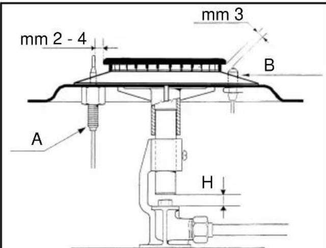
A = TERMOCOPPIA / THERMOCOUPLE / THERMOCOUPLE / TEPMOIAPATERSRMRPAR/ ΘEPMOSTOIXEIY / TERMOPAR
B=CANDELA/BOUGIE/SPARKPLUG/CBEHACBEHA 3AKHTAHRAAAMBOYZI/BUJIA
Figure/Figures/Figures/PnCyHKn/Figuras/Eikóvεç/Figuras