I 80 RH - Heating Jøtul - Free user manual and instructions
Find the device manual for free I 80 RH Jøtul in PDF.
| Product Type | Insert fireplace (I 80 RH) |
| Brand | Jøtul |
| Material | Cast iron |
| Surface treatment | Paint / enamel (depending on version: Classic, Harmony, Panorama) |
| Fuel | Wood only |
| Max log length | 50 cm |
| Connection | Top, diameter 200 mm |
| Nominal power | 9.0 kW |
| Efficiency | 71% (at 9.0 kW) |
| CO rate (13% O2) | 0.25% |
| Flue gas temperature | 350 °C |
| Recommended draft | 12 Pa |
| Flue gas mass flow | 8.4 g/s |
| Operating mode | Intermittent |
| Air supply | Adjustable top air inlet; proper room ventilation required |
| Safety distance to ceiling | 800 mm minimum from combustible ceiling |
| Maintenance and cleaning | Regular glass cleaning, ash removal, chimney sweeping at least 2 times per year |
| Spare parts available | Lining plates, deflector, glass, gaskets, draft key, grilles, side panels, etc. |
| Standard | EN 13229 |
| Warranty | Subject to Jøtul conditions (see manual) |
Frequently Asked Questions - I 80 RH Jøtul
User questions about I 80 RH Jøtul
0 question about this device. Answer the ones you know or ask your own.
Ask a new question about this device
Download the instructions for your Heating in PDF format for free! Find your manual I 80 RH - Jøtul and take your electronic device back in hand. On this page are published all the documents necessary for the use of your device. I 80 RH by Jøtul.
USER MANUAL I 80 RH Jøtul
GB - Installation and Operating Instructions 10
4.6 Klargjøring/montering
1.0 Relationship to the authorities 10
2.0 Technical data 10
3.o Safety precautions 11
4.o Installation 11
5.o Operation instructions 13
6.o Maintenance 14
7.o Service 15
8.o Optional Equipment 15
9.o Operational problems - troubleshooting .... 17
Figures 58
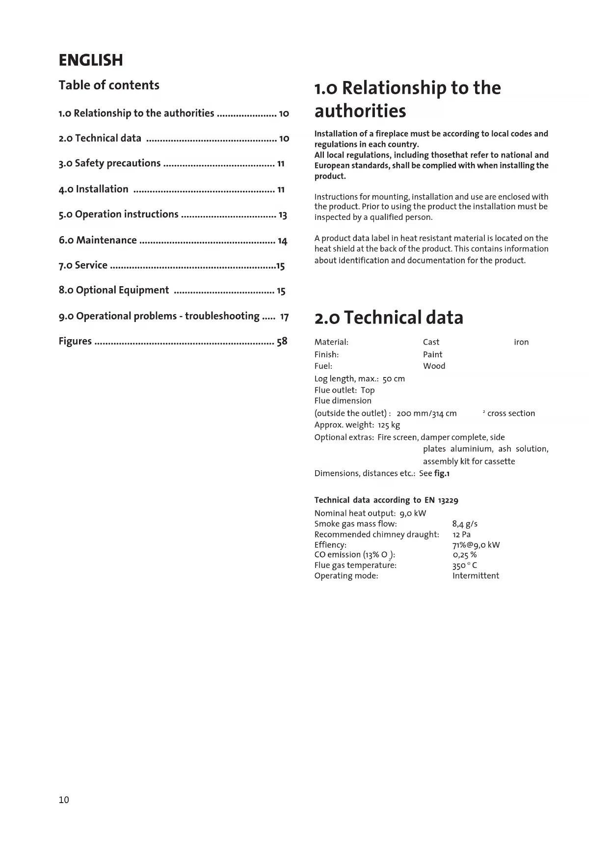
1.0 Relationship to the authorities
Installation of a fireplace must be according to local codes and regulations in each country.
All local regulations, including those that refer to national and European standards, shall be complied with when installing the product.
Instructions for mounting, installation and use are enclosed with the product. Prior to using the product the installation must be inspected by a qualified person.
A product data label in heat resistant material is located on the heat shield at the back of the product. This contains information about identification and documentation for the product.
2.0 Technical data
Material: Cast iron
Finish: Paint
Fuel: Wood
Log length, max.: 50 cm
Flue outlet: Top
Fluedimension
(Outside the outlet): 200 mm/314 cm ^2 cross section
Approx. weight: 125kg
Optional extras: Fire screen, damper complete, side
plates aluminium, ash solution, assembly kit for cassette
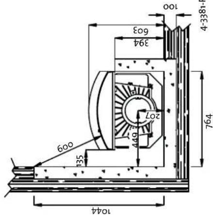
Dimensions, distances etc.: See fig.1
Technical data according to EN 13229
Nominal heat output: 9,0 kW
Smoke gas mass flow: 8,4 g/s
Recommended chimney draught: 12 Pa
Efficiency: 71% @9,o kW
CO emission (13% O): 0,25%
Flue gas temperature: 350°C
Operating mode: Intermittent
3.0 Safety precautions
3.1 Fire preventive measures
Any use of the fireplace may represent some danger. Therefore, respect the following instructions:
- Ensure that furniture and other flammable materials do not get too close to the fireplace.
- Let the fire die. Never put it out with water as this may damage the product.
- The fireplace gets warm when used and may cause burns if touched.
- Only remove ashes when the fireplace is cold.
- Ash must be properly disposed of outdoors, or emptied where it does not entail a fire hazard.
3.2 Air supply
Warning! Please ensure that there is adequate air supply from the outdoors to the room in which the fireplace is to be installed. Ensure that air vents in the room where the fireplace is located are not blocked.
An inadequate air supply could cause smoke gas to escape into the room. This is very dangerous! Symptoms of this include smoky smell, drowsiness, nausea and feeling ill.
Avoid using mechanical fan vents in a room with a fireplace. This may cause negative pressure and draw poisonous gasses into the room.
4.o Installation
4.1 Floor
Foundations
Ensure that the floor is strong enough for the fireplace. See «2.0 Technical data» for weights. It is recommended that flooring which is not fastened to the foundations - so-called floating flooring - is removed during installation.
Wooden floor protection
Requirements for the floor plate:
The floor plate must be in accordance with national laws and regulations. (See Building regulations)
We recommend that you contact the local Jøtul dealer prior to the installation.
Any flooring made of combustible material, such as linoleum, carpets, etc. must be removed from under the floor plate.
Requirement for protecting combustible flooring in front of fireplace
The front plate must be in accordance with national laws and regulations. Contact your local building authorities regarding restrictions and installation requirements.
4.2 Wall
Distance to walls made of combustible material covered by insulation - see fig. 1
Requirements for insulation
50 mm rock wool 120kg / m^3 foliated on one side with aluminium.
Distance from the product to the insulation on the back panel: o mm.
Requirements for the stove surround
The stove surround must be made in an combustible material and be carried out in accordance with the requirements indicated under section: 3.0 Safety precautions'.
Note that the entire back panel within the surround must be covered by insulation.
If the stove cowling is bricked up to the ceiling and the ceiling is made of combustible material, on top of the warming chamber and the cowling vents an extra ceiling panel must be installed to avoid heating the ceiling.
For example use:
Rock wool 100 mm thick on top of a steel plate min. 0,9 mm.
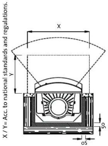
Ensure airing out the top of the stove cowling - for example an opening towards the ceiling, or approx. 5cm^2 opening (fig. 2).
Note: Remember that it should be possible to sweep and to inspect the installation.
4.3 Air circulation (fig. 2)
Air should be allowed to flow between the insert and the brickwork, and it is very important that there is a free air supply to the draft catcher on top of the insert. See fig. 2.
The required air vent sizes for Jøtul I 80 RH (for air circulation) are:
Base: Minimum of 500 cm ^2 free ventilation.
Top: Minimum of 750 cm free ventilation.
This is a safety measure to prevent a build up of heat in the surround, and also to ensure sufficient heat emission into the room.
If the house is badly ventilated, the room must be equipped with extra fresh air circulation, for example by means of separate air channels or a separate channel directly to the top of the fireplace.
The fresh air channel should be as straight as possible. It should be possible to close the channel with a damper in order to keep out cold air when the fireplace is not being used.
4.4 Ceiling
Jotul 180 RH have been approved for:
A min. 800 mm distance from warm air opening in the hood's top to a ceiling of combustible material.
ENGLISH
4.5 Chimney
- The fireplace can be connected to a chimney and flue pipe approved for solid fuel fired fireplaces with flue gas temperatures specified in «2.0 Technical data».
- The chimney's cross-section must be at least as big as the flue pipe's cross-section. See «2.0 Technical data» when calculating the correct chimney cross-section.
- Connection to the chimney must be carried out in accordance with the installation instructions from the supplier of the chimney.
- Before making a hole in the chimney the fireplace should be test-mounted in order to correctly mark the position of the fireplace and the hole in the chimney. See fig. 1 for minimum dimensions.
- Ensure that the flue pipe is inclined all the way up to the chimney.
- Use a flue pipe bend with a sweeping hatch that allows it to be swept.
Be aware of the fact that connections must have a certain flexibility in order to prevent movement in the installation leading to cracks.
N.B. A correct and sealed connection is very important for the proper functioning of the product.
Warning! Weight from the fireplace must not be transferred to the chimney. The fireplace must not interfere with the ability of the chimney to move and it must not be fastened to the chimney.
Note: A guide is published by the British Flue and Chimney Manufacturers' Association which contains general information on chimneys and flues.
Recommended chimney draught, see «2.0 Technical data», If the draught is too strong you can install and operate a flue damper to control the draught.
In case of chimney fire
- Close all hatches and vents.
- Keep the firebox door closed.
- Check the loft and cellar for smoke.
- Call the fire service.
- Before use after a fire an expert must check the fireplace in order to ensure that it is fully functional.
4.6 Preparation/installation
Make sure that the fireplace insert is free of damage before commencing with the installation.
The product is heavy! Make sure you have assistance when erecting and installing the fireplace.
Attaching the legs (fig. 3) and securing the base heat shield
- Unpack the insert. Take the box out with its contents and if necessary, the burn plates. Remove both the ash lip and the bottom frame (applies to Harmony/Panorama) situated at the rear of the combustion chamber. Close the doors.
- To make the installation easier, remove the entire front including the doors. See section: Service.
-
Place the wooden pallet and the cardboard packaging on the floor and lay the fireplace carefully down on its back.
-
Assemble the 3 legs (A) with the adjustable joints (C) with the aid of 3 screws and washers, which are in the plastic bag. Attach the joints to the product with the aid of 3 countersunk screws (B) M6x25mm and washers. These are already attached to the base of the fireplace. Adjust he legs so that the required height is achieved.
- Assemble the base heat shield (E) under the base of the fireplace by using 1 nut M6 and washer.
- Lift the combustion chamber up.
- NB! The product is heavy. You will need help during assembly and when the product is being placed into position.
- The final adjustments to the legs should only be made after the insert has had a trial assembly. The bracket (D) should be placed under the screw heads, both to protect the surface and to prevent the insert from slipping out of place. The final adjustment is done with the aid of M10x45mm screws which are attached to the joints.
- Replace the parts you removed in order to make the handling of the fireplace easier.
Ash lip
Place the ash lip next to the bottom frame.
Assembly of the flue connecting pipe (fig. 4)
- The flue connecting pipe (A), which is packed in the box, is placed on the top of the fireplace.
- Place one clamp iron (B) on each side. These are held in place with a screw (C) M8x30mm and with nuts.
4.7 Set up/installation
Assembly of the chimney
- First, have a trial assembly of the insert, without making holes in the chimney. See the measurements of the fireproof wall in figure 1.
- The insert may be assembled with an 200mm flue pipe.
- Place the insert into its final position. With the aid of a furnace cement (or possibly some rope seal), the flue pipe is placed in the insert's smoke outlet.
- NBI It is important that the joints are tightly sealed. False air or the like can impair the function of the fire.
4.8 Checking the operating parts (fig. 5)
When the insert is in place, always check the control equipment. These should be freely mobile and appear satisfactory. The loose handle can be used when the fireplace is hot.
Top draught (A)
Left position = closed.
Right position = fully open.
Door locks (Classic/Harmony) (B)
Place the handle in the groove on the right hand door and turn it upwards. Open and close the left door in the same way.
Door lock (Panorama) (C)
Damper (D)
Damper is accessory - (if equipped)
Pushed in = open.
Pulled out = closed.
5.o Operating instructions
5.1 Choice of fuel
Always use quality firewood. This will give you optimal results, and will not cause any damage to the product.
5.2 Jøtul's definition of quality firewood
With good quality firewood we mean logs of, for example: Birch, beech and oak.
Good quality wood should be dried so that the water content is approx. 20% .
To achieve that, the wood should be cut during late winter or early spring, then cut and stacked to ensure proper airing and covered to prevent it from absorbing rainwater. The logs should be taken indoors in autumn for use during the winter season.
The amount of energy obtainable from 1kg of wood varies very little. On the other hand the specific weight of the different kinds of wood varies considerably. As an example, a certain volume of birch will provide less kWh than the same volume of oak, which has a higher specific weight.
The amount of energy produced by 1 kg quality wood is about 3,8kWh.1kg of completely dry wood (0%) humidity) produces approximately 5kWh , while wood with a humidity level of 60% produces only around 1,5kWh / kg .
Consequences of using damp wood may include:
- Appearance of soot/tar on the glass, in the fireplace and in the chimney.
The fireplace emits little warmth. - Risk of chimney fire as a consequence of accumulation of soot in the fireplace, flue pipe and chimney.
The fire may die out.
Be especially careful never to lay a fire using any of the following materials:
Household waste, plastic bags, etc.
- Painted or impregnated wood (highly toxic)
- Chipboard or laminated boards
Driftwood
This may harm the product and pollute the atmosphere.
N.B. Never use combustible liquids such as petrol, kerosene, red spirit or similar to start the fire. This may cause harm to both yourself and the product.
5.3 Log length and amount
The maximum length of logs to be used is 50~cm . Nominal heat emission from a Jotul I 80 RH is 9,0 kWh. The requirement for nominal heat emission is 2,9 kg of quality firewood per hour. The Jotul I 80 RH is a product that uses an extra air supply to enable the afterburning of hazardous gases and particles. It is important that the system is used correctly.
Another important factor for proper fuel consumption is that the logs are the correct size. The size of the logs should be:
Kindling:
Length: Approx 35 cm
Diameter: 2-5 cm
Amount per fire: 8-10 pieces
Firewood (split logs):
Recommended length: 30-40 cm
Diameter: Approx. 8-12 cm
Intervals for adding wood: Approx. every 60 minutes
Size of the fire: 3kg
The product is intended for intermittent combustion. By intermittent combustion one means normal use of a fireplace, meaning that each fire should burn down to embers before new firewood is added.
- Open the air vent on the door fully by moving the vent all the way to the right (fig. 5A - 5B).
- Place two medium sized logs in/out on each side of the base.
- Crumple some newspaper (or birch/bark) between these and add some kindling wood in a criss-cross pattern on top and light the newspaper. Increase the size of the logs gradually.
- Leave the door slightly open until the logs catch fire.Close the ignition vent when the firewood has ignited and the fire is burning briskly.
- Check that the afterburning (secondary combustion) starts. This is best indicated by yellow, flickering flames at the air chamber.
- Then regulate the rate of combustion to the desired level of heating by adjusting the draught vent (fig. 5A). (Use a glove, for example, when the handle is warm.)
Nominal heat emission is achieved when the air vent is open approximately 80% (fig. 5A).
5.6 Adding firewood
Each load should burn down to embers before new firewood is added. Open the door slightly and allow the negative pressure to level out prior to opening the door completely.
- Add the wood and make sure that the air vent is fully open for a few minutes until the wood has caught fire.
- Close the air vent (fig.5A) once the wood has properly ignited and is burning well. Check that afterburning (secondary combustion) starts.
N.B. Danger of overheating: the fireplace must never be used in a manner that causes overheating.
Overheating occurs when there is too much wood and/or air so that too much heat is developed. A sure sign of overheating is when parts of the fireplace glow red. If this happens, reduce the ventilation opening immediately.
Upon suspicion of excessive/poor draught in the chimney, seek professional help. See also «2.0 Technical data» and «4.5 Chimney» for information.
5.7 Using fireplace during the transition from winter to spring
During a transitional period with sudden fluctuations in temperature, negative smoke draught or under difficult wind conditions, disturbances in the chimney draught may occur so that the smoke gasses are not drawn out.
ENGLISH
One should then use less firewood and have a larger opening in the air vents so that the wood burns fresher and faster. In this was the draught in the chimney will be maintained. To avoid accumulated ash, it should be removed more often than usual. See «6.2 Ash removal».
6.o Maintenance
6.1 Cleaning the glass
Jotul 80 RH is equipped with top draught (air wash). Through the air vent air is sucked in above the fireplace and washed down along the inside of the glass. This system has the advantage that it provides better combustion and reduces the buildup of soot deposits on the glass.
Still, some soot will always stick to the glass, but the quantity will depend on the local draught conditions and adjustment of the draught vent. Most of the soot layer will normally be burned off when the draught vent is opened all the way and a fire is burning briskly in the fireplace.
Good advice! For normal cleaning, moisten a paper towel with warm water and add some ash from the burn chamber. Rub it over the glass and then clean the glass with clean water. If it is necessary to clean the glass more thoroughly we recommend a glass cleaner (follow the instructions for use on the bottle).
6.2 Ash removal
- Use a scoop or similar to remove the ash through the door.
- Always leave some ash as a protective layer on the bottom of the fireplace.
- Ash must be placed in a metal container with a sealed lid.
Also see the description below about how to handle ash: "3.0 Safety precautions".
6.3 Cleaning and soot removal
Soot deposits may build up on the internal surfaces of the stove during use. Soot is a good insulator and will therefore reduce the stove's heat output. If soot deposits accumulate when using the product, they can be easily removed by using a soot remover. An annual internal cleaning is necessary to get the best heating effect from the product. It is a good idea to do this in connection with the sweeping of the chimney and flue pipes.
6.4 Sweeping of flue pipes to the chimney
The flue must be swept through the stove's door opening. The baffle plate must first be removed. See separate section under: "7.0 Service".
6.5 Control of the stove
Jotul recommends that you personally control your stove carefully after sweeping/cleaning. Check all visible surface areas for cracks. Also check that all joints are sealed and that
the gaskets are in the correct position. Any gaskets showing signs of wear or deformation must be replaced.
Thoroughly clean the gasket grooves, apply ceramic glue (available from your local Jotul dealer), and press the gasket well into place. The joint will dry quickly.
6.6 External maintenance
Painted products may, after a few years of use, change colour. The surface should be cleaned and brushed free of any loose particles before applying a new coat of paint.
Enamelled products must only be cleaned with a clean, dry cloth. Do not use water and soap. Any stains can be removed with a cleaning fluid (oven cleaner etc.).
7.o Service
Warning! Any unauthorised change to the product is illegal. Only use original spare parts!
7.1 Changing the burn plates (fig. 6)
- Lift up the ash moulding (A) on the one side so that it comes out of the harbours on the side of the combustion chamber and then remove it.
- Remove the side burn plates (B) by lifting these up slightly and pull out. If they are stuck, a screwdriver may be used to flip them up.
- Then lift the back burn plate (C) out.
- Start with the back burn plate first. Then the side burn plates are shoved into place.
7.2 Changing the baffle plate
- Lift the baffle plate up in the front edge and pull it out through the doors.
7.3 Dismantling/assembly of the doors
Classic and Harmony
- In order to remove the doors, they must first be opened.
- Loosen the grub screws and pull out the doors.
- When assembling the doors, any washers under the lowermost grab screws must be put in place.
- Change the gasket at the same time.
Panorama
- In order to remove the door, it must first be opened.
- Remove the self-locking mechanism, loosen the grab screw and pull out the door.
- When assembling the door, any washers under the grub screw must be put in place.
- Change the gasket at the same time.
7.4 Dismantling/assembly of the front (fig. 8)
- Dismantle the doors, ash lip, baffle plate and the damper - if it has been installed. (See relevant section).
- Unscrew the screws (A) in the lower front edge of the combustion chamber half way out and pull the washers all the way out towards the screw head.
- Loosen the screws (B) in the upper front edge of the combustion chamber. These screws have washers and nuts on the inside. When the last screw is loosened, you must support the front so that it does not fall forward.
- Lift the front off.
Assembly is achieved by placing the front on the two half-screwed-in screws (A) in point 2. The front has tracks where the screws should fit into place. - Push the frame into the upper edge - lift it up so that it reaches the top. Fasten the frame with screws (B) M6x30mm and washers with nuts on the inside of the combustion chamber.
8.o Optional equipment
8.1 Damper - cat. no. 340955 (fig. 9)
Assembly of the damper (prior to installation)
- Remove the flue connecting pipe if it has already been connected.
- Unscrew the screw (A) which is on the door frame at the top in the middle. (The nut is situated at the back).
- Hook the regulating bar (B) on the damper (C) from the left. Put it down into the smoke pipe opening through the hole in the door frame. Lower the damper so that the cams fall down into the harbours (D) on the smoke outlet. The damper is put into place with its curved part facing backwards.
Note! Included in the damper package is one control bar Jotul 180 Classic and one for Harmony/Panorama. The bar for Classic can be identified by a bend in the middle - in section E.
- Screw the knob on the regulating bar.
Dismantling/assembly of the damper (after the brickwork is completed)
- If the damper is to be dismantled, the burn plates, and baffle plate must be removed (see relevant sections).
- Screw the knob off the regulating bar.
- Lift the damper out of its harbour and pull it down. Unhook the regulating bar and the damper can be removed through the doors.
- Pull the regulating bar into the smoke bell and out again through the door opening.
- The damper is put into place with its curved side facing backwards. Hook the regulating bar on the damper from the left, lift it up and place it in its harbour in the flue pipe.
- Screw the knob back on to the regulating bar.
8.2 The top and bottom grids (fig. 10)
- Bottom grid: The bottom grid (A) should be placed under the front frame. The adjusting screws on the legs should be adjusted so that the bottom grid fits.
- Top grid: Place one cage nut (B) on each side of the top of the insert. Fasten the nuts loosely with a nut M6 and a washer, so that they can be pushed a little.
- Place the top grid (C) on the front frame and fasten it with two body screws (D).
- Adjust the top grid so that it is even with the front frame.
- Loosen the two body screws (D) and remove the top grid.
- Now the nuts which hold the cage nuts in place can be tightened.
- Re-fasten the top grid.
8.3 The aluminium panel
If you wish to cover up any openings at the side of the insert towards the side wall of the fireplace, black varnished side panels made of aluminium are available. These are 775mm high and are adapted to the insert which is assembled with a top and bottom grid. If adjustment is necessary, they are easy to cut with a bow saw or an angle grinder.
ENGLISH
Side panel, narrow: catalogue no: 340818 - breadth 76mm, height 775mm (packs of 2). Side panel, broad: catalogue no: 340817 - breadth 120mm, height 775mm (packs of 2).
The broad and narrow side panels can be combined to give a total breadth of 180mm, which may also be mounted at an angle if necessary.
Assembly of the aluminium panel (fig. 11)
- The bracket (A) is fitted onto the side walls of the fireplace with plugs and screws.
- Press the side panel (B) into the bracket. First put some mortar on the base of the fireplace behind the panel, as a support.
- If you combine the narrow and broad panels, the angle towards the side wall of the fireplace can only be max. 70^ .
8.4 Enamelled front panels (fig. 12)
Narrow side -
Catalogue no. 340996 (2 units of 35 × 573 ~mm )
Broad side -
Catalogue no. 340995 (2 units of 103x573)
- Remove the front (see relevant section on: Service).
- Attach the panels (A) with countersunk head screws through the 2 slits at the sides of the combustion chamber. Make sure that the panels are parallel, ie: equally far from the side borders and level with the ends of the front panel narrow top, if that has been installed.
- Put the front in place.
- Narrow top - Catalogue no. 340998 (703x103mm)
- Broad top - Catalogue no. 340997 (838x103mm)
- Screw the two clasps (C) to the panel with M6x10mm screws.
- Place the panel so that it lies on the inside of the front frame. Tighten the clasps with M6x20mm screws and nuts on the brackets for insert's heat shield.
8.5 Ash compartment cat.no.340732 (fig.13)
- Remove the internal screw in the middle of the bottom of the combustion chamber so that the fire plate and the cross bar can be removed.
- Lay a gasket (B) (enclosed in the box) along the edge of the hole.
Lower the ash pail mantle (C) down through the bottom of the combustion chamber. - Lock the ash pail mantle with 4 plate screws from the inside.
- Fasten the heat shield to the floor (fig. 4-A) under the bottom of the ash pail mantle with M6x10mm screws and nuts.
- Put the ash compartment (D) into position in the mantle. NB! The side which does not have a lip is placed against the back wall.
- Lay the fire grate (E) in place in the combustion chamber.
8.6 Fire screen
Classic : Cat. No. 340758
Harmony :Cat.No.340979
Panorama : Cat. No. 340979
When the fireplace is being used with the doors open, always use a fire screen. It can be put in place with two claws at the bottom end and a spring clip which is pressed into the opening of the door at the top.
8.7 Self-closing door mechanism (Panorama)
Adjusting the door mechanism (fig. 14)
- When adjusting/dismounting, the spring must be set tighter or looser if the door is too hard or to easy to close.
- First loosen the adjustment screw (A). Use universal tool (B) or similar tool and tighten the spring by turning the screw at the top of the shaft (C) clockwise.
- Keep the spring under tension while the adjustment screw is tightened again.
- The spring tension may be reduced with time and will then have to be adjusted again.
9.o Operational problems -troubleshooting
Poor draught
- Check the length of the chimney and that it complies with national laws and regulations. Make sure that the minimum cross section on the chimney is large enough. See also «2.0 Technical data» and «4.5 Chimney» for information.
- Make sure that there is not anything preventing the smoke gasses from escaping: Branches, trees, etc.
The fire extinguishes after a while
- Make sure that the firewood is sufficiently dry
Find out whether there is negative pressure in the house, close mechanical fans and open a window close to the stove. - Check that the air vent is open.
- Check that the flue outlet is not clogged by soot.
Unusual amount of soot accumulates on the glass
Some soot will always stick to the glass, but the quantity depends on:
- Humidity of the fuel.
- The local draught conditions
Regulating the air vent.
Most of the soot will normally burn off when the air vent is opened all the way and a fire is burning briskly in the fireplace.«6.1 Cleaning the glass - good advice».
FRANCAIS
Sommaire
0 200mm/314 cm²section
Poids:
Ca.125 kg
Options:
Dimensions, distances
Voir fig.1.
a respecter,etc.:
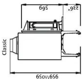
Mälene gjelder ubehandelde producerkter. Etter lakkering erer emaljering kan mälene variere noe Dimensions refer to untreated products. After painting or enamelling dimensions may have small divergences.
* = Adjustble up 100mm
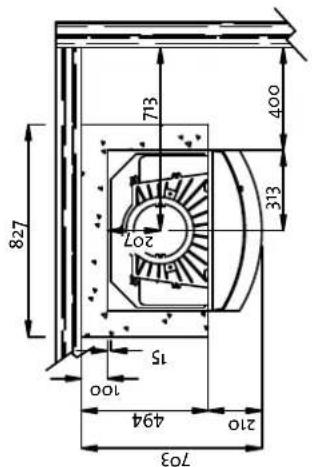
Min. installationsjalnsal / Min. installation measurements
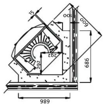
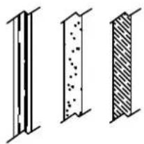
Combustible wall
Non combustible wall
Insulation
M'slare girderubehord
* = Adjustble up 100mm
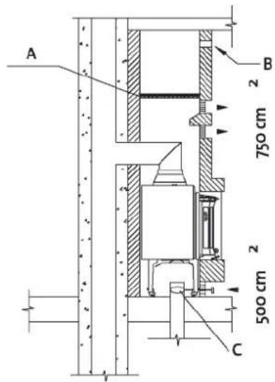
Fig. 2
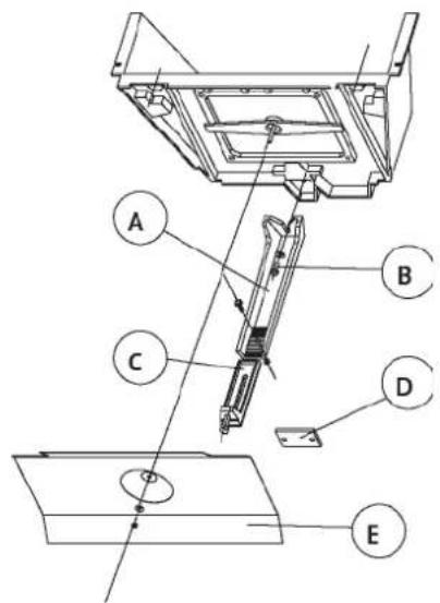
Fig. 3
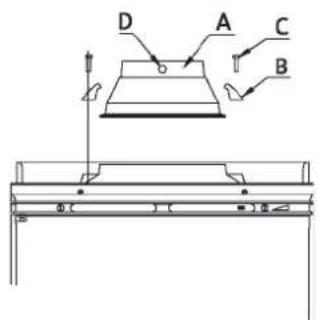
Fig.4 Fig.5
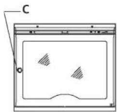
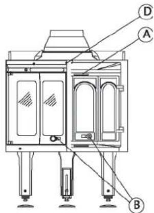
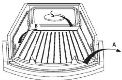
Fig. 6
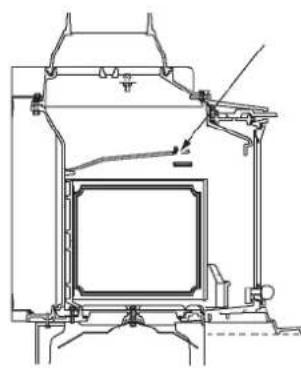
Fig. 7
| Fig. 8 Fig. 9 B A 72mm t80mm C D B A | C E B A |
| Fig. 10 | |
| Fig. 12 | Fig. 13 |
| Fig. 14 |
Checked
Utfort Kontrollpunkt Controlled item
Jøtul pursue a policy of constant product development. Products supplied may therefore differ in specification, colour and type of accessories from those illustrated and described in the brochure.
Jøtul AS has a quality system that conforms to NS-EN ISO 9001 for product development, manufacturing, and distribution of stoves and fireplaces. This policy gives our customers quality and safety piece of mind as a result of Jøtul's vast experience dating back to when the company first started in 1853.