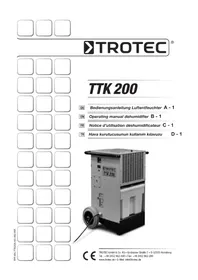
TTK 200 - Humidifier TROTEC - Free user manual and instructions
Find the device manual for free TTK 200 TROTEC in PDF.



| Product type | Condensing mobile dehumidifier |
| Brand | Trotec |
| Model | TTK 200 |
| Item number | 1.120.000.200 |
| Dehumidification performance (20°C/60% RH) | 17 L/24h |
| Max. performance | 35 L/24h |
| Recommended room volume | Up to 200 m³ |
| Continuous dehumidification volume | Up to 400 m³ |
| Operating temperature range | 0 °C to 40 °C |
| Relative humidity range | 35 % to 100 % RH |
| Airflow rate | 230 m³/h |
| Power supply | 230 V / 50 Hz |
| Average power consumption | 0.45 kW |
| Max. power consumption | 0.8 kW |
| Current draw | 2.8 A (protection 4 A) |
| Compressor | Rotary vane |
| Refrigerant | R407c |
| Sound level (at 3 m) | 52 dB(A) |
| Condensate tank capacity | 11 L |
| Tank autonomy | Approximately 12 h |
| Dimensions (L x W x H) | 480 x 510 x 720 mm |
| Net weight | 34 kg |
| Service hour counter | Factory integrated |
| Air filter | Washable, included |
| Automatic defrost | Yes, by hot gas |
| Automatic tank full shutdown | Yes |
Frequently Asked Questions - TTK 200 TROTEC
User questions about TTK 200 TROTEC
0 question about this device. Answer the ones you know or ask your own.
Ask a new question about this device
Download the instructions for your Humidifier in PDF format for free! Find your manual TTK 200 - TROTEC and take your electronic device back in hand. On this page are published all the documents necessary for the use of your device. TTK 200 by TROTEC.
USER MANUAL TTK 200 TROTEC
INHALTSVERZEICHNIS
This publication replaces all previous announcements. No part of this publication may be reproduced, processed using electronic systems, replicated or distributed in any form, without our written authorisation. Subject to technical changes. All rights reserved. Names of goods are used without guarantee of free usage keeping to the manufacturer's syntax. The names of goods used are registered and should be considered as such. We reserve the right to modify design in the interest of on-going product improvement, such as shape and colour modifications. The scope of delivery may vary from that in the product description. All due care has been taken in compiling this document. We accept no liability for errors or omissions. © TROTEC®
01. SAFETY NOTES
This manual should be read carefully before setting up / using the apparatus, and it should always be kept close to the place of use or on the machine!
The apparatus was subjected to extensive material, function and quality tests before delivery.
Nevertheless, dangers can arise from the use of the apparatus if it is incorrectly used by untrained personnel!
Please observe the following instructions:
- The apparatus should not be set up and operated in rooms where a danger of explosion exists.
- The apparatus should not be set up and operated in saliferous environments or where the ambient air contains oil, sulphur or chlorine.
- The apparatus must be placed upright in a stable position.
- The apparatus should not be subjected to contact with running water.
- Unrestricted access to the air intake and air exhaust must always be guaranteed.
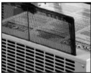
- The air intake side must be kept free of dirt and loose objects.
- Never insert foreign objects into the apparatus.
- The apparatus must never be covered or transported during operation.
- All electrical cables outside of the apparatus are to be protected from damage (e. g. by animals).
- Extension of the mains cables must be carried out with due regard for the installed load of the apparatus, cable length and application.
- The apparatus may only be transported upright, the condensate container must be emptied before each change of location.
- It is not permitted to operate or utilise the apparatus in a manner other than that described in this manual. All liabilities and warranty claims are invalidated in the event of non-compliance with this stipulation.
△ Work on the refrigeration system and the electrical equipment may only be carried out by an authorised & qualified company!
02. DESCRIPTION OF APPARATUS
The apparatus has been designed for automatic air dehumidification. It can be easily transported and set up due to its compact dimensions.
The apparatus works in accordance with the condensation principle. It is equipped with a hermetically-sealed refrigeration system, a low-noise, low-maintenance ventilator and a mains cable with plug.
The apparatus has an operating console for function control. The automatic control, the condensate container with integrated overflow protection and the connection piece for direct extraction of condensate permit fault-free continuous operation. The apparatus conforms with the fundamental health & safety requirements of the applicable EU legislation.
Application locations for the apparatus:
The apparatus is used wherever dry rooms are required and wherever subsequent economical damage (e.g. due to mould formation) is to be avoided.
The apparatus is predominantly used to dry and dehumidify:
• Living, sleeping, shower or cellar rooms
- Laundries, holiday homes, caravans and motor homes, boats
And for the continuous drying of:
- Warehouses, archives, laboratories
- Bathrooms, washing rooms & changing rooms.
Principle of operation:
The appliance works on the condensation principle (see figure A: schematic diagram of the operating principle).
The moist room air is sucked in by the ventilator and fed through the evaporator and the condenser which lies behind it.
Heat is extracted from the air in the cold evaporator. The room air is cooled to below the dew point and the water vapour in the air condenses as condensate or frost on the lamellae of the evaporator.
The dehumidified, cooled air is warmed again at the condenser (heat exchanger) and is blown out at a temperature of approximately 5 °C above room temperature. This treated, dryer air is then mixed with the ambient air. Due to the continuous room air circulation through the apparatus, the air humidity in the place of use is reduced continually to the desired relative humidity. Dependent on the air temperature and the relative air humidity, the condensed water drops continually, or only during the periodic defrosting phases, into the condensate pan and then into the condensate container located below via the integrated outlet.
When the maximum fill state of the condensate container is reached, the tank warning lamp on the operating console lights and the apparatus switches off. In the case of unattended continuous operation with external condensate connection, the condensate is continually drawn off via a hose connection (see the section “Continuous operation with external condensate connection”).
![graph TD A["A"] --> B["A1"] B --> C["A2"] C --> D["A3"] D --> E["A4"] E --> F["A5"] F --> G["A6"] G --> H["A7"] H --> I["A8"] I --> J["A9"] style A fill:#f9f,stroke:#333 style J fill:#bbf,stroke:#333](/content/2026/02/393688/images/59818e56491161073747eed3da90abaa6164d9d03b7cc206a3cdb8bb98fb178b.jpg)
A. Schematic representation of the principle of operation
| A.1 Moist room air | A.6 Solenoid valve |
| A.2 Evaporator | A.7 Fan |
| A.3 Condenser | A.8 Compressor |
| A.4 Drip tray | A.9 Dehumidified room air |
| A.5 Water outlet |
03. transportation of apparatus
The appliance is equipped with lockable wheels and grip recesses on both sides of the housing. Furthermore, the appliances can be stacked to save storage space.
When transporting the appliance it must be kept upright and secured by appropriate means such as lashing straps.
Each time before transporting:
- Before moving the apparatus, switch it off and remove the mains plug from the socket.
- Then empty the condensate container. Please watch out for subsequent dripping condensate.
- Do not pull the apparatus by its mains cable.
04. set-up
For optimised, economical and safe operation of the apparatus, you should in all cases observe the following instructions (see also diagram B).
- The apparatus is to be placed upright and stable to ensure unimpeded flow of the condensate into the condensate container.
- If possible, place the apparatus in the centre of the room to guarantee optimum air circulation.
- In all cases, the apparatus is to be kept at least 50 cm from walls.
- Make sure that air can be drawn in at the air inlet and exhausted at the rear air outlet without hindrance.
- Do not operate the apparatus in the heaters or other sources of heat.
- Ensure that the room that is to be dried or dehumidified is closed off from the surrounding atmosphere.
- Ensure that doors and windows are avoid frequently entering or leaving the room.
- If the apparatus is used in a dusty ensure that the applicable care & maintenance measures are followed. See the section “Care and maintenance”.
Important information on electrical connection:
- In accordance with DIN VDE 0100, Part apparatus must be connected to supply points with earth leakage protection.
- If the apparatus is used in wet areas such as laundries, bathrooms or similar, it must be protected by an inbuilt earth leakage protection switch that conforms with regulations.
B
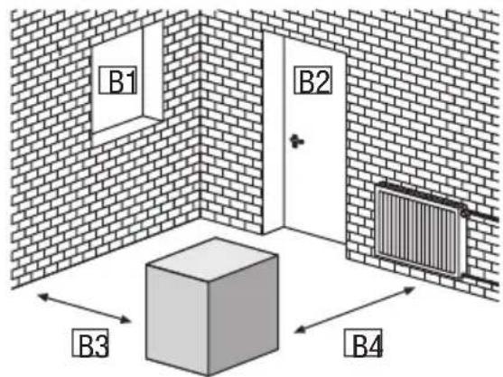
B. Set up
B.1 Keep windows closed
B.2 Keep doors closed
B.3 Keep apparatus at least 0,5m away from walls
B.4 Keep apparatus away from heaters or other sources of heat vicinity of
05.commissionInG osed, and
Before each commission, or dependent on local requirements, the intake and outlet openings must be checked for foreign bodies and the intake filter must be checked for fouling. Blocked or dirty grilles and filters should be cleaned immediately, see the section "care & maintenance".
Important instructions before commissioning: 704. the
- Cable extensions must have an adequate crosssection.
- Cable extensions must be either completely unrolled from the drum or completely rolled!
- The condensate container must be inserted correctly.
- Economical dehumidification is no longer guaranteed with this class of apparatus at room temperatures of less than 2 °C and/or relative air humidity of less than 35 %.
- Our product range contains special dehumidification for use under such climatic conditions. Our staff will be pleased to discuss your requirements with you.
Commissioning of the apparatus:
- Insert the apparatus' plug into a correctly-fused mains socket (230 V/50 Hz).
- Check that the tank warning lamp is not lit.
- Press the mains switch so that it is in operating mode "I".
- For dehumidifying operation, set the rotary control switch to the desired operating level.
The appliance is now operating and working at the desired dehumidifying level. To switch off the appliance, press the mains switch so that it is in operating mode "0".
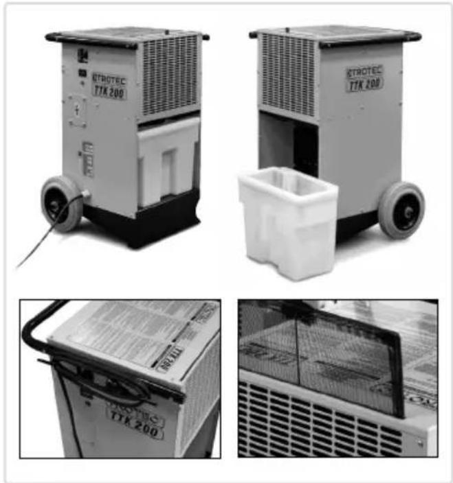
Information on operating the apparatus:
- The appliance works fully automatically after being switched on until it is switched off by the condensate tank rocker when the tank is full.
- If the power supply is interrupted during operation, the apparatus does not automatically switch itself on again when the power supply is restored.
- If the apparatus is to be used in continuous operation, mum position. with an external condensate connection, please read the section "Continuous operation with external condensate connection".
- The ventilator runs continually until the apparatus is switched off so that the sensor built into the apparatus can always correctly determine the air humidity within the room.
Information on first use and the different types of operation:
When using the dehumidifier for the first time, turn the rotary control switch to its maximum position. Let the appliance run for a while in this operating mode. At the start, the dehumidifier will absorb large quantities of moisture and will continue to do so until the relative humidity has been reduced. After that, the appliance will absorb less moisture. This does not mean that the dehumidifier is not working properly, but rather that the humidity of the air has been reduced.
As soon as you notice the pleasant feeling of dryer air and that the unpleasant odour of damp has disappeared, you can switch the appliance to one of two different operating modes: hygrostat control or permanent operation.
With stepless hygrostat control, you can now set the rotary control switch to a position between off and permanent operation, depending on your personal requirements. To automatically maintain the current humidity of the room air, carefully reduce the dehumidifying power by slowly turning the rotary control switch anticlockwise towards the off position and leaving it in the exact position where the compressor switches off. The built-in hygrostat stores the desired relative humidity value and automatically switches the appliance on or off respectively when the humidity drops below or exceeds this value, effectively maintaining the set humidity level.
In permanent operation mode, the appliance de-humidifies the air continuously, irrespective of the humidity of the air. For permanent operating mode, leave the rotary control switch unchanged at its max-
Information on dehumidification performance:
Dehumidification performance is exclusively dependent on environmental conditions, room temperature, relative air humidity and observation of the instructions in the section "Set-up".
The higher the room temperature and the relative humidity, the higher the dehumidification performance. For use in living quarters, a relative air humidity of approximately 50 to 60 % is sufficient, whilst this should not exceed 50 % in warehouses, archives, etc.
Automatic defrosting
The humidity contained in the ambient air condenses on cooling and, dependent on the air temperature and the relative humidity, coats the evaporator fins with frost or ice. This layer of frost or ice is automatically defrosted by the apparatus.
When required, the automatic hot gas defrosting system built into the apparatus starts the defrosting cycle. The dehumidification operation is halted briefly during the defrosting phase.
Condensate container
From time to time, it will be necessary to empty the incorporated condensate container. When the container is full, the dehumidification operation is interrupted and the tank warning lamp illuminates.
- Turn off the appliance
- Carefully pull out the condensate tank towards the front.
- Pour the condensate down the drain.
- Clean the tank with a clean cloth.
- Replace the tank in the appliance.
- Turn on the appliance again
Continuous operation with external condensate connection:
A connecting nozzle is located under the condensate (collecting) pan. A suitable water hose can be connected to this. If necessary, remove the condensate tank from the appliance to do this. During continuous operation, the condensate can now be drained into a receptacle placed at a lower level. Take care that the hose drains downhill into the receptacle so that the condensate can flow from the condensate pan in an unimpeded manner!
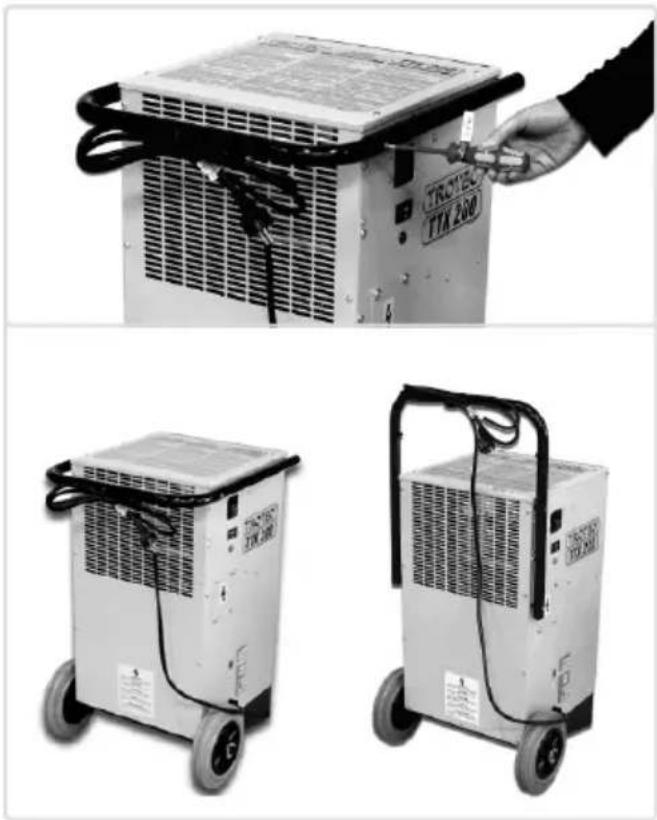
06. water Drain
Firstly, the water can be collected in the water tank included in the scope of delivery; secondly, a hose can be used to conduct the water into a drain or a large external tank and thirdly, a condensate pump can be used to constantly pump out the water (see section 8.2 Accessories)
6.1 Using the water tank and the automatic stop function
The tank has a capacity of 11 litres. The appliance switches itself off automatically when it is full and the liquid level indicator lamp lights up (see section 4.2). The lamp goes off and the appliance switches itself on again automatically as soon as the tank has been emptied.
6.2 Conducting the water away using a hose
The water tank can be reconfigured so as to allow the water to be conducted away into a drain or a large external tank via a hose. The tank has a connecting tube on the left frontal side. There is a plug on the end of the neck of the tube. Pull out the plug and put it in the small round drain opening on top of the tank. A normal or common hose (approx. 12mm in diameter) can be fitted to the connecting tube.
When using a hose, please ensure that the water can drain off by creating a gradient for the water to flow away.
6.3 Using a condensate pump
See section 8.2
Please observe the instructions for using a condensate pump as laid down in the operating manual when a employing a condensate pump.
07. CARE AND MAINTENANCE
Regular preventative maintenance and observation of certain prerequisites will guarantee fault-free operation and a long service life.
After every period of prolonged operation, and at least once per year, the apparatus should be checked and thoroughly cleaned.
All moving parts have been treated with low-maintenance permanent lubrication. The entire refrigeration system is a maintenance-free hermetically-sealed system and may only be maintained by authorised specialist companies.
The mains plug must be removed from the mains socket before any work is carried out on the apparatus!
- Keep the apparatus free from dust or other deposits.
-
Only use a dry or damp cloth to clean the apparatus. Do not use running water.
-
Do not use cleaning agents that are caustic or contain solvents and only use appropriate cleaning agents even in the case of heavy soiling.
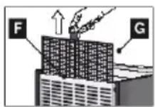
- Check the air intake filter regularly for fouling. It should be cleaned or replaced as necessary.
△ Work on the refrigeration system and the electrical equipment may only be carried out by an authorised & qualified company!
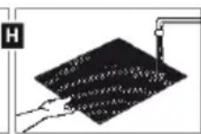
Cleaning the condenser and evaporator:
This work requires the apparatus housing to be opened, and therefore may only be carried out by authorised & qualified companies!
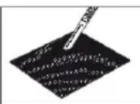
- Clean the condenser and the evaporator either by blowing or sucking them through, or by using a soft brush. Do not use running water.
- Please note that the fins can easily be or bent.
- Carefully clean the inside surfaces of the apparatus, the condensate pan with hose connection, the ventilator and the ventilator housing.
- Reinstall all dismounted parts correctly
- Check that the apparatus is functioning corr and carry out an electrical safety examination. Important recycling information! The apparatus uses the environmentally-friendly and ozoneneutral refrigerant. In accordance with legal stipulations, or those that apply locally, the refrigerant/oil mixture used in the apparatus must be disposed of correctly.
08. DehumIDIFler accessories
8.1 Hygrostat
A hygrostat can be installed to bring the relative humidity in the room down to the desired level. The appliance switches itself off automatically when the desired level has been reached and switches itself on again when the set values have been exceeded. The hygrostat is installed on the side of the appliance below the mains switch. All hygrostats are factory-fitted with this upgrade option. This allows new as well as used driers to be upgraded after the fact.sites will guarantee fault-free operation and a long service life.
8.2 Condensate pump set
A condensate pump ser can be installed on the inside of the appliance as an additional accessory. The kit is designed to accommodate configurations involving long water draining systems or for permanent drying of unsupervised rooms. The pump conducts the water away when, for example, there is a condensation dryer in the cellar. The innovative “plug & pump” technology enables quick and trouble-free installation.
- wirInG DlaGram
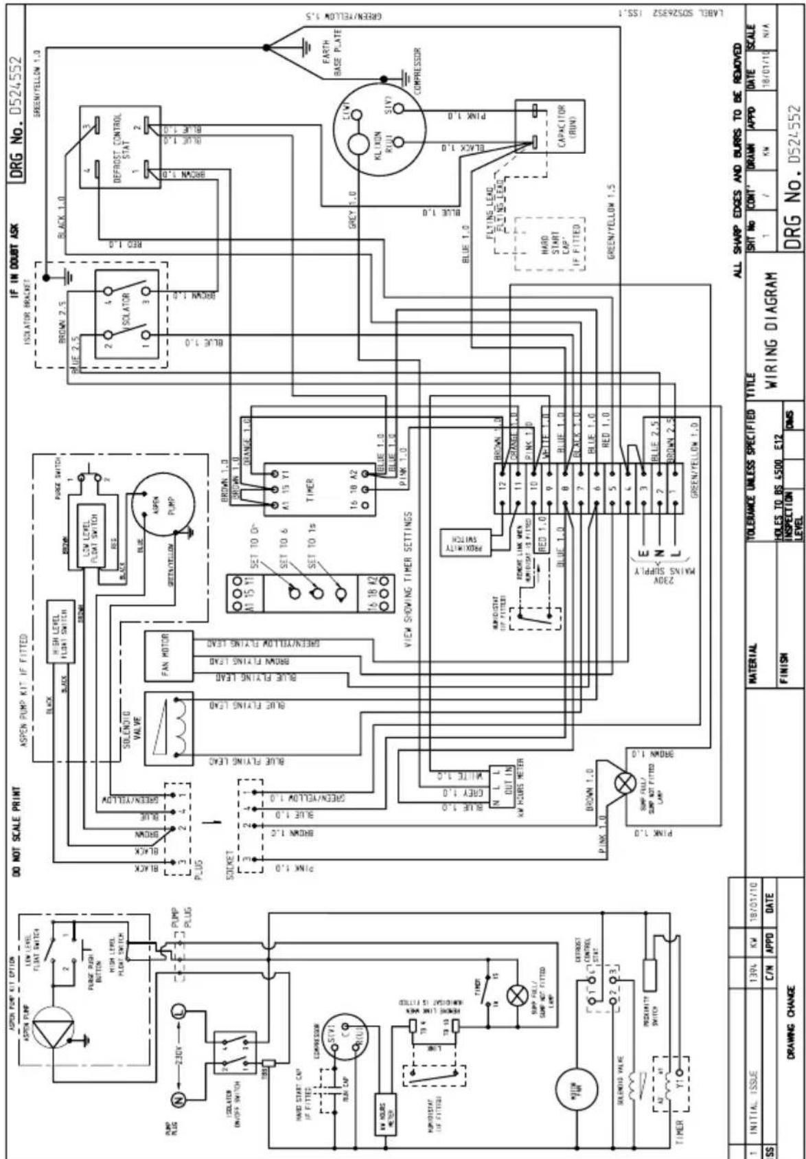
10. technical Data
Working range temperature 0 °C - 40 °C
Working range humidity 35 - 100 % r. H.
Dehumidifying capacity max. 61 l/day
Dehumidifying capacity (at 20 °C / 60 % r.F.) 17 l/day max. 35 l/day
Air performance max. 1.480 m 3 /h
Refrigerant R 407c
Refrigerant quantity 625 g
Electrical connection 230 V
Frequency 50 Hz
Nominal current max. 4,5 A
Power consumption max. 950 W
Sound pressure level LpA 1m 1) 52 dB (A)
Condensate container 12 l
Depth 510 mm
Width 480 mm
Height 720 mm
Weight 34 kg
1) Noise measuring DIN 45635 - 01 - KL 3
11. spare parts
You may only use spare parts that have been approved by the manufacturer. Original spare parts provide the necessary guarantee that the appliance can be operated safely and trouble-free. The position of the spare parts can be taken from the plan view and the side view.
-
Base plate
-
Top cover
-
Cover panel
-
Motor and blade
-
Ratary compressor
-
Electric panel assy
-
Spring
-
Side panel
-
Handle
-
Side panel controls
-
Blanking plate
-
Shield plate
-
Inlet grille
-
Microswitch
-
Solenoid valve
-
Solenoid coil
-
Pilot light amber 240v
-
Hours run meter (panel mount)
-
Plug/lead assembly
-
Refrigerant R 407c
-
Wheel
-
Rotary switch 2 pole on/off
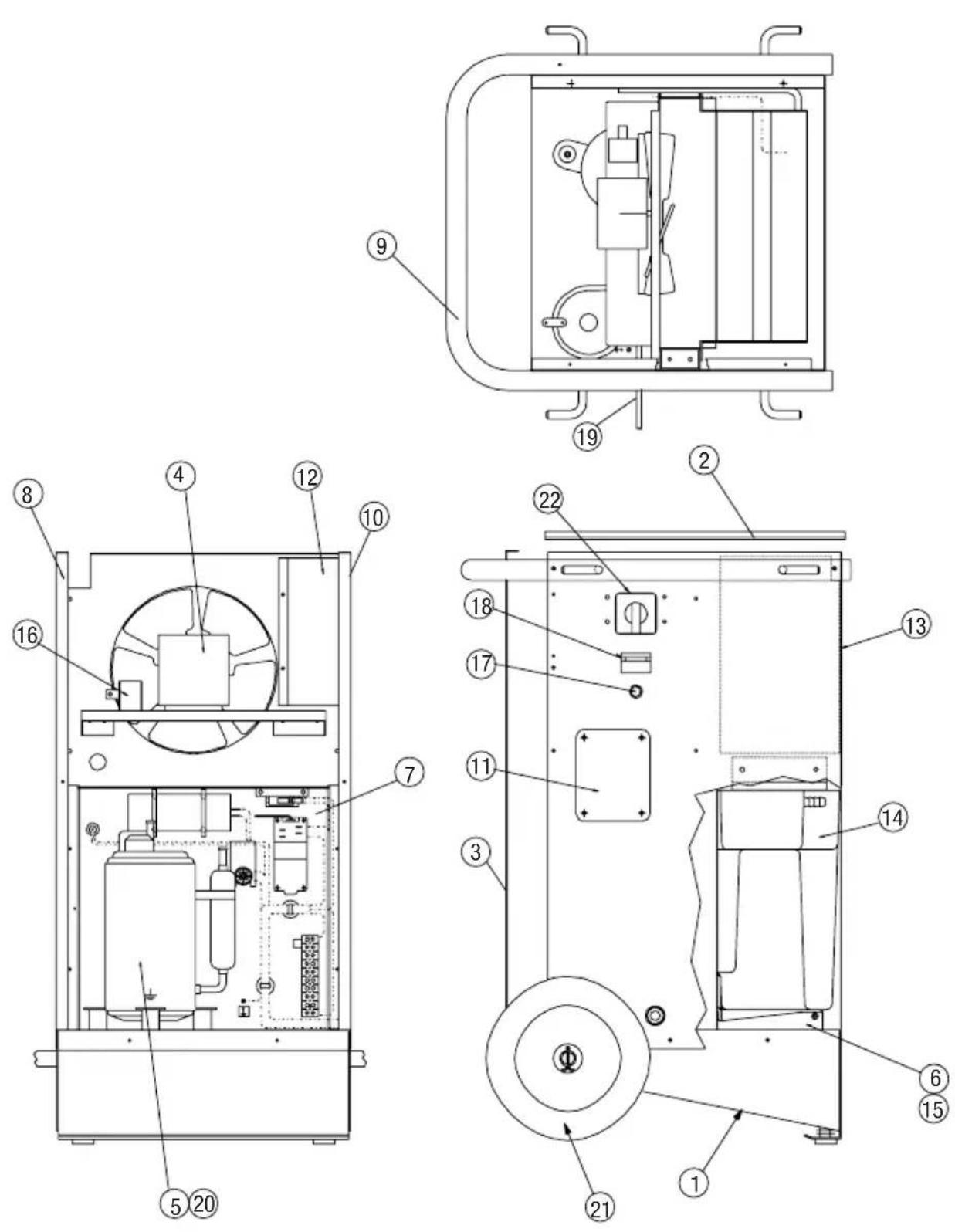
12. TROUBLESHOOTING
The fault-free operation of the apparatus has been confirmed by repeated tests at the factory. However, if a loss of function should occur, please check the apparatus in accordance with the following list.
The apparatus will not start:
- Check the mains connection. 230 V / 1 \~ / 50 Hz.
- Check the inbuilt mains fuse.
- Check the mains plug for damage.
The apparatus runs, but no condensation formation:
- Check the fluid level in the condensate tank. The 'tank full' indicator lamp must not be lit.
- Check the microswitch of the condensate tank rocker.
- Check the room temperature. The working range of the apparatus is between 2 and 32 °C.
- Check the air humidity: minimum 35 humidity.
- Check which operating mode is set. The humidity of the room air in which the unit is operating must be above the selected range. If necessary, turn the rotary control switch clockwise towards permanent operation.
- Check the air intake filter for fouling. Clean or replace it if necessary.
- Have the heat exchanger fins checked for soiling. This examination requires the apparatus to be opened up and hence must be carried out by an authorised specialist company.
The mains plug must be removed from the mains socket before any work is carried out on the apparatus.
The apparatus is making a lot of noise or vibrates, condensate is running out:
- Check that the apparatus is standing upright on a level surface.
- Have the condensate pan and connection pi checked for fouling.
If the apparatus does not function correctly after carrying out the above checks, please contact an authorised specialist company.
The mains plug must be removed from the mains socket before any work is carried out on the apparatus.
13. DISPOSAL
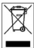
In the European Union electronic equipment must not be treated as domestic waste, but must be disposed of professionally in accordance with Directive 2002/96EU of the
European Parliament and Council of 27th January 2003 concerning old electrical and electronic equipment. At the end of its life please dispose of this instrument in a manner appropriate to the relevant legal requirements.
14. GUARANTEE
- The manufacturer guarantees the appliance against material or manufacturing faults arising from normal and orderly use in compliance with the operating instructions for the duration of a period of one year after the product has been delivered to the customer.
- The manufacturer will either replace or renew free of charge and as seen fitting any material or manufacturing fault that occurs within a year of having been delivered to the customer.
-
The manufacturer does not provide any further guarantees. This applies in particular to any damage resulting from improper use or any malfunctioning of the appliance as well as any costs or information that have not been expressly approved in writing by the manufacturer, or any other consequential damage.
-
Any damage that occurs as a result of dirt or soiling is also exempt from the guarantee.
• Appliances for which the guarantee still applies - Any damage that occurs as a result of dirt or soiling is also exempt from the guarantee.
- Appliances for which the guarantee still applies
are to be delivered free of transportation charges. The customer must bear the travelling costs in the event that any service technicians are required. - The guarantee no longer applies when the appliance has been altered outside the factory with regard to its configuration or technical construction.
- You may only use original Trotec spare parts. Repairs may only be carried out by Trotec. The guarantee is no longer valid in case of noncompliance.
TROTEC®
CE
EN Declaration of Conformity
The Manufacturer: TROTEC® GmbH & Co. KG
Grebbener Straße 7
D-52525 Heinsberg
hereby declares that the dehumidifier as described below is in conformity with EU guidelines as stated herein with respect to its conception and construction, as well as the type of model placed on the market.
Important Notice:
Any improper use, installation, servicing etc. or any alterations carried out by any other persons on the factory-made appliance render this declaration null and void.
Type of model: mobile dehumidifier
Series:
TTK
200
Applicable regulations: MA-RL 89/392/EWG Machine Guidelines (98/37/EG)
NS-RL 73/23/EWG Voltage Guidelines
EMV-RL 89/336/EWG EMV Directive
ElektroG-RL 2002/96/EG Electrical and Electronic Law
(2003/108/EG)
Applied Norms: EN 292-1; EN 292-2, EN 294; EN 349, EN 60204-1;
Heinsberg, 07 April 2009
ElektroG-RL 2002/96/EG Electrical and Electronic Law
(2003/108/EG)
6. su aKIŞI

- INHALTSVERZEICHNIS
- SAFETY NOTES
- PLEASE OBSERVE THE FOLLOWING INSTRUCTIONS
- DESCRIPTION OF APPARATUS
- APPLICATION LOCATIONS FOR THE APPARATUS
- AND FOR THE CONTINUOUS DRYING OF
- PRINCIPLE OF OPERATION
- TRANSPORTATION OF APPARATUS
- EACH TIME BEFORE TRANSPORTING
- SET-UP
- IMPORTANT INFORMATION ON ELECTRICAL CONNECTION
- SET UP
- 05.COMMISSIONING OSED, AND
- IMPORTANT INSTRUCTIONS BEFORE COMMISSIONING: 704. THE
- COMMISSIONING OF THE APPARATUS
- INFORMATION ON OPERATING THE APPARATUS
- INFORMATION ON FIRST USE AND THE DIFFERENT TYPES OF OPERATION
- INFORMATION ON DEHUMIDIFICATION PERFORMANCE
- AUTOMATIC DEFROSTING
- CONDENSATE CONTAINER
- CONTINUOUS OPERATION WITH EXTERNAL CONDENSATE CONNECTION
- WATER DRAIN
- 6.1 USING THE WATER TANK AND THE AUTOMATIC STOP FUNCTION
- 6.2 CONDUCTING THE WATER AWAY USING A HOSE
- 6.3 USING A CONDENSATE PUMP
- CARE AND MAINTENANCE
- CLEANING THE CONDENSER AND EVAPORATOR
- DEHUMIDIFLER ACCESSORIES
- 8.1 HYGROSTAT
- 8.2 CONDENSATE PUMP SET
- TECHNICAL DATA
- SPARE PARTS
- TROUBLESHOOTING
- THE APPARATUS WILL NOT START
- THE APPARATUS RUNS, BUT NO CONDENSATION FORMATION
- THE MAINS PLUG MUST BE REMOVED FROM THE MAINS SOCKET BEFORE ANY WORK IS CARRIED OUT ON THE APPARATUS
- THE APPARATUS IS MAKING A LOT OF NOISE OR VIBRATES, CONDENSATE IS RUNNING OUT
- DISPOSAL
- GUARANTEE
- TROTEC®
- CE
- THE MANUFACTURER: TROTEC® GMBH & CO. KG
- IMPORTANT NOTICE
- SU AKIŞI
Brand : TROTEC
Model : TTK 200
Category : Humidifier