
Balnea Silence SO6210 - Heating ROWENTA - Free user manual and instructions
Find the device manual for free Balnea Silence SO6210 ROWENTA in PDF.
| Brand | Rowenta |
| Model | Balnea Silence SO6210 |
| Category | Heating |
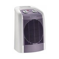
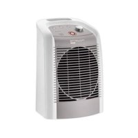
| Product Type | Fan-forced electric supplementary heater |
| Maximum power | 2400 W |
| Silence power | 1200 W |
| Power supply | 220-240 V ~ 50 Hz |
| Electrical class | II (double insulation) |
| Protection rating | IP21 |
| Installation | Vertical wall mounting with supplied bracket |
| Operating modes | Off, cold ventilation, Silence (1200W), Max (2400W) |
| Thermostat | Adjustable with frost protection setting |
| Frost protection | Automatically maintains temperature above 0°C |
| Safety | Thermal cut-off in case of overheating, thermal fuse |
| Maintenance | Clean air inlet and outlet grilles at least once a year |
| Cleaning | With a slightly damp cloth, without abrasive or corrosive products |
| Included accessories | Wall bracket, user manual |
| Recommended use | Damp rooms (bathroom, kitchen) in compliance with standards |
| Housing material | Flame retardant plastic |
Frequently Asked Questions - Balnea Silence SO6210 ROWENTA
User questions about Balnea Silence SO6210 ROWENTA
0 question about this device. Answer the ones you know or ask your own.
Ask a new question about this device
Download the instructions for your Heating in PDF format for free! Find your manual Balnea Silence SO6210 - ROWENTA and take your electronic device back in hand. On this page are published all the documents necessary for the use of your device. Balnea Silence SO6210 by ROWENTA.
USER MANUAL Balnea Silence SO6210 ROWENTA
natural_image
Line drawing of a vertical cylindrical device with horizontal slats and a top handle, showing internal structure without any text or symbols.Réf. NC00011665
DESCRIPTIF TECHNIQUE
F
fixe
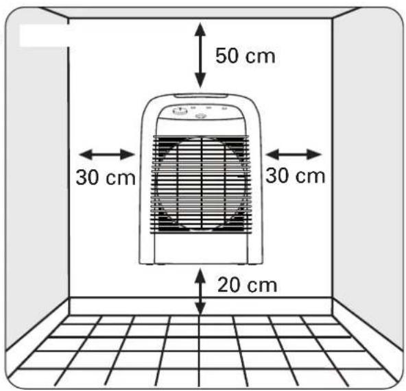
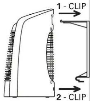
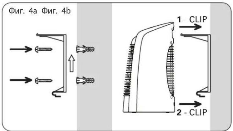
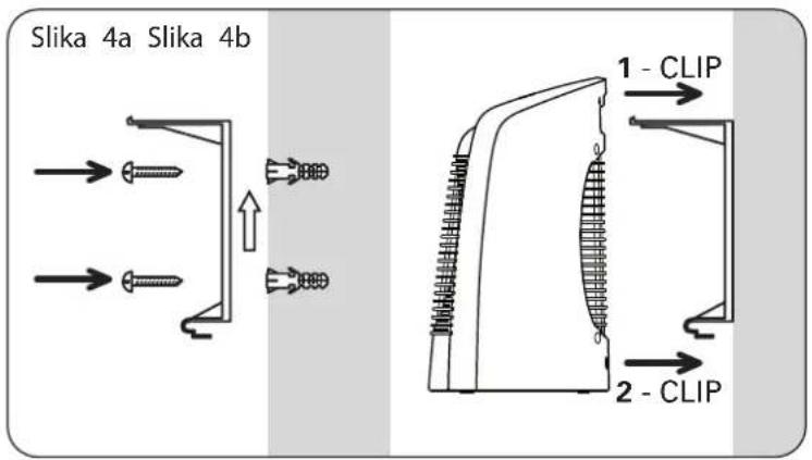
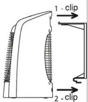
Figure 4a Figure 4b

AVERTISSEMENTS
F
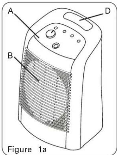
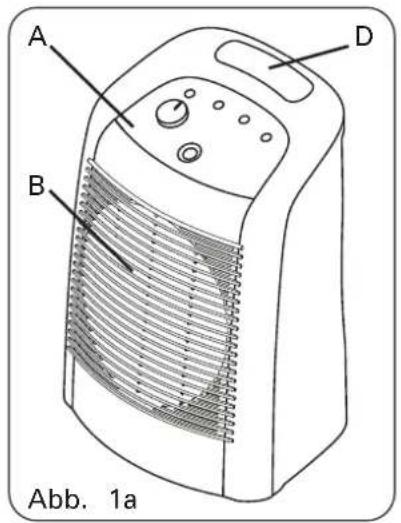
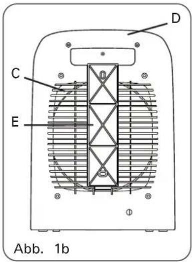
A. Control panel
B. Air outlet screen
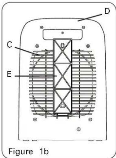
C. Air intake screen
D. Transport handle
E. Wall bracket
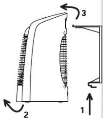
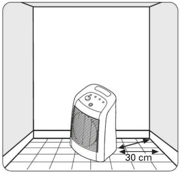
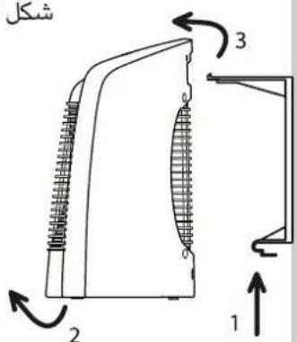
Fig 2. Mobile position Fig 3. Stationary position
natural_image
Line drawing of a portable electric heater inside a room with a 30 cm height dimension标注 (no text or symbols on the device itself)
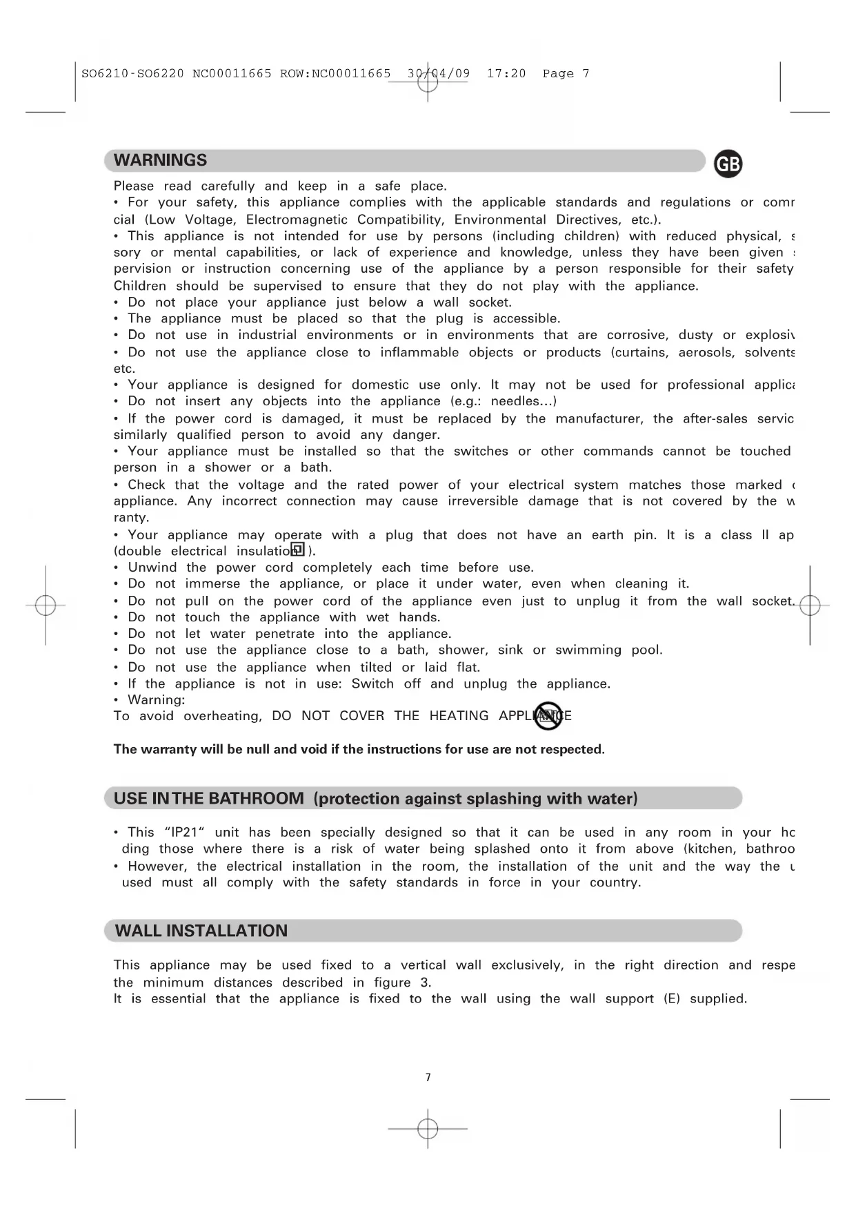
WARNINGS

Please read carefully and keep in a safe place.
- For your safety, this appliance complies with the applicable standards and regulations or commercial (Low Voltage, Electromagnetic Compatibility, Environmental Directives, etc.).
-
This appliance is not intended for use by persons (including children) with reduced physical, sensory or mental capabilities, or lack of experience and knowledge, unless they have been given a pervision or instruction concerning use of the appliance by a person responsible for their safety. Children should be supervised to ensure that they do not play with the appliance.
-
Do not place your appliance just below a wall socket.
- The appliance must be placed so that the plug is accessible.
- Do not use in industrial environments or in environments that are corrosive, dusty or explosive
- Do not use the appliance close to inflammable objects or products (curtains, aerosols, solvents etc.
- Your appliance is designed for domestic use only. It may not be used for professional applica
- Do not insert any objects into the appliance (e.g.: needles...)
- If the power cord is damaged, it must be replaced by the manufacturer, the after-sales service similarly qualified person to avoid any danger.
- Your appliance must be installed so that the switches or other commands cannot be touched person in a shower or a bath.
- Check that the voltage and the rated power of your electrical system matches those marked appliance. Any incorrect connection may cause irreversible damage that is not covered by the warranty.
- Your appliance may operate with a plug that does not have an earth pin. It is a class II ap (double electrical insulation).
- Unwind the power cord completely each time before use.
- Do not immerse the appliance, or place it under water, even when cleaning it.
- Do not pull on the power cord of the appliance even just to unplug it from the wall socket.
- Do not touch the appliance with wet hands.
- Do not let water penetrate into the appliance.
- Do not use the appliance close to a bath, shower, sink or swimming pool.
- Do not use the appliance when tilted or laid flat.
- If the appliance is not in use: Switch off and unplug the appliance.
- Warning:
To avoid overheating, DO NOT COVER THE HEATING APPLIANCE
The warranty will be null and void if the instructions for use are not respected.
USE IN THE BATHROOM (protection against splashing with water)
- This "IP21" unit has been specially designed so that it can be used in any room in your heating those where there is a risk of water being splashed onto it from above (kitchen, bathroom
- However, the electrical installation in the room, the installation of the unit and the way the U used must all comply with the safety standards in force in your country.
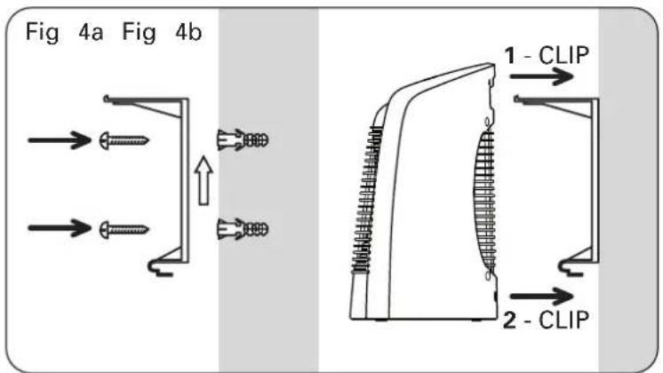
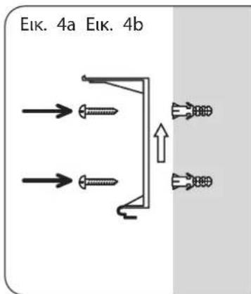
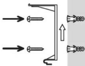
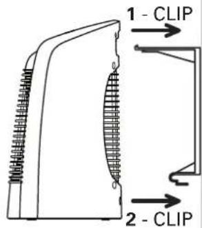
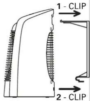
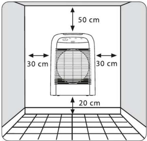
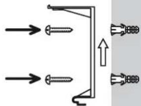
WALL INSTALLATION
This appliance may be used fixed to a vertical wall exclusively, in the right direction and respe the minimum distances described in figure 3.
It is essential that the appliance is fixed to the wall using the wall support (E) supplied.
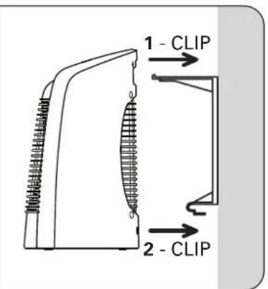
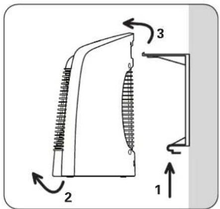
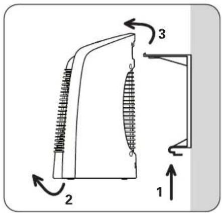
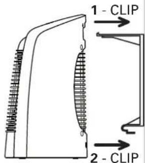
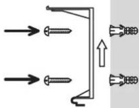
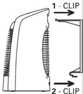
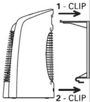
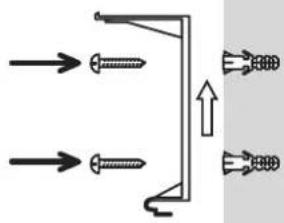
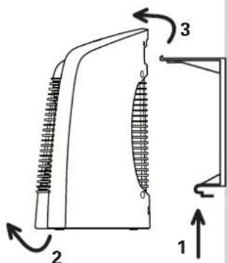
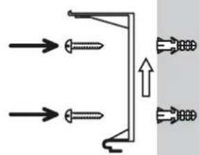
Wall Attachment: see fig. 4a.
- Attach the wall bracket with appropriate screws and plugs following the direction of the arrow
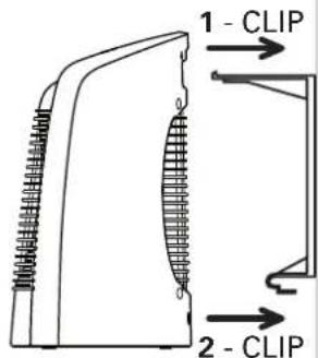
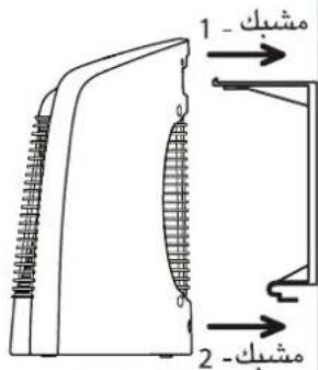
- Insert the upper wall-bracket hook in the unit's transport handle, and clip the lower wall-brack hook onto the unit.
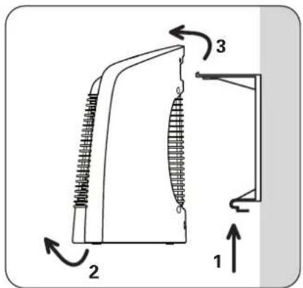
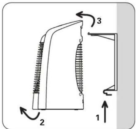
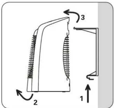
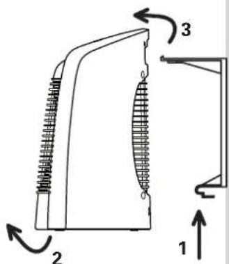
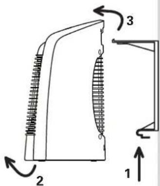
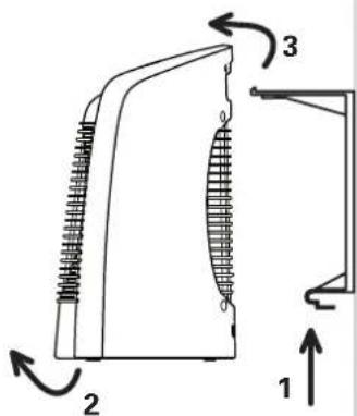
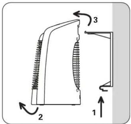
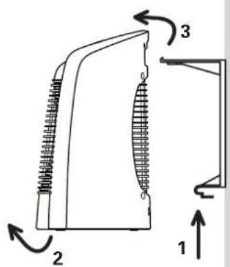
Taking Down the Unit: see fig. 4b.
- Maintain a solid grip on the unit and push down upon the lower tongue of the wall bracket
- Pull the unit out from the bottom.
- Lift the unit up and remove it from the upper hook.
SAFETY
In the event of abnormal overheating, a safety device shuts down the appliance and then autor cally restarts it once ithas cooled. If the fault persists or gets worse, a thermal fuse shuts the pliance down definitively and it must then be taken to an approved service centre.
OPERATION
Each time before use, check that the appliance is in good condition.
Especially check that:
- the position of the appliance described in these instructions is respected.
- the air inlet and outlet grids are in no way obstructed.
- the appliance is placed on a horizontal, stable surface.
MODEL SO6210 :
Button 1: Operating mode selector:
0 : OFF Position
: Cold ventilation position
● : "Silence" position, 1200W ventilated and regulated
●●: 2400W position, ventilated and regulated
Indicator light 2: The indicator light is lit when the appliance is operated with the knob 1.
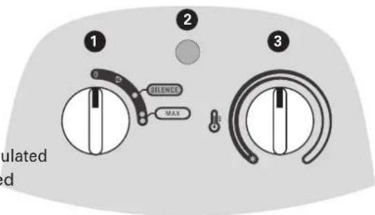
Button 3 : Thermostat (knob 1 must be in the ● or ●● position).
- Adjust the temperature setting, according to your own comfort.
- Frost-free setting: This setting enables you to automatically maintain the temperature above 0°C in a normally insulated room, whose volume corresponds to the power of your appliance.
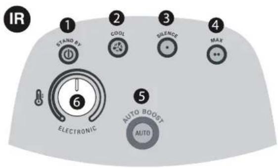
MODEL SO6220 :
When switching on the power to the appliance (appliance plugged into the mains), the appliance in the "STOP" mode, and the knob 1 is lit.
The appliance makes a beep every time the control knobs are moved.
Button 1 "STAND-BY": Switching off the appliance (a cooling cycle of a few seconds is carried out automatically each time before it is switched off; during this cycle, the button flashes)
Button 2 "COOL": Cold ventilation position.
Button 3 "SILENCE": "Silence" position, 1200W ventilated and regulated.
Button 4 « MAX » : 2400W position ventilated and regulated.
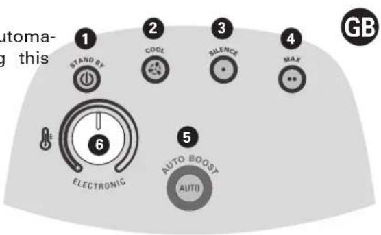
Button 5 "AUTO BOOST": Automatic operation mode
- 10 minutes: 2400W ventilated unregulated
- 20 minutes: 1200W ventilated and regulated (depending on the position of the button
- Stops automatically after the 30 minutes of operation.
Button 6 : Thermostat (on the SILENCE, MAX and AUTO-BOOST functions).
- Adjust the temperature setting, according to your own comfort.
- Frost-free setting: This setting enables you to automatically maintain the temperature above 0 in a normally insulated room, whose volume corresponds to the power of your appliance.
TAKING CARE OF YOUR APPLIANCE
• The appliance must be unplugged and left to cool down before carrying out any work on it.
- Do not clean it with abrasive or corrosive products.
- Clean with a damp cloth.
- Clean the air inlet and outlet grids at least once a year (with a vacuum cleaner if necessary)
STORAGE
- It is extremely important that the unit be allowed to cool down before it is put away.
- The power cord can be rewound for storage.
- When you are not using your appliance, store it in a dry place.
INTHE EVENT OF PROBLEMS
- Never dismantle your appliance yourself. A poorly repaired appliance may be dangerous for th
- Stop using your appliance and contact an Authorized Service Centre if :
- your appliance has fallen
- it does not work correctly
- Before contacting one of our Approved Service Centres (see enclosed list), ensure that:
- the appliance is set to normal operating mode;
- the air inlet and outlet grills are totally clear.
ENVIRONMENT PROTECTION FIRST!
① Your appliance contains valuable materials which can be recovered or recycled.
Leave it at a local civic waste collection point.
BESCHREIBUNG
D
HINWEISE
D
WAARSCHUWINGEN

AVVERTIMENTI
I
ADVERTENCIAS
E
AVISOS
P
natural_image
Line drawing of a portable electric heater inside a room with a 30 cm measurement dimension (no text or symbols on the device itself)
ΠΡΟΕΙΔΟΠΟΙΗΣΕΙΣ

natural_image
Line drawing of a portable electric heater inside a room with a 30 cm dimension label (no text or symbols on the device itself)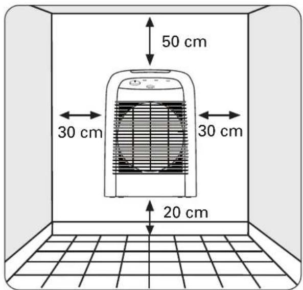

UYARILAR

natural_image
Line drawing of a portable electric heater inside a room with tiled floor and 30 cm dimension label (no text or symbols on the device itself)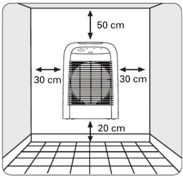

WARNINGAR
S
natural_image
Line drawing of a portable electric heater inside a room with a 30 cm height dimension标注 (no text or symbols on the device itself)

VAROITUKSIA

natural_image
Line drawing of a portable electric heater inside a room with a 30 cm height dimension标注 (no text or symbols on the device itself)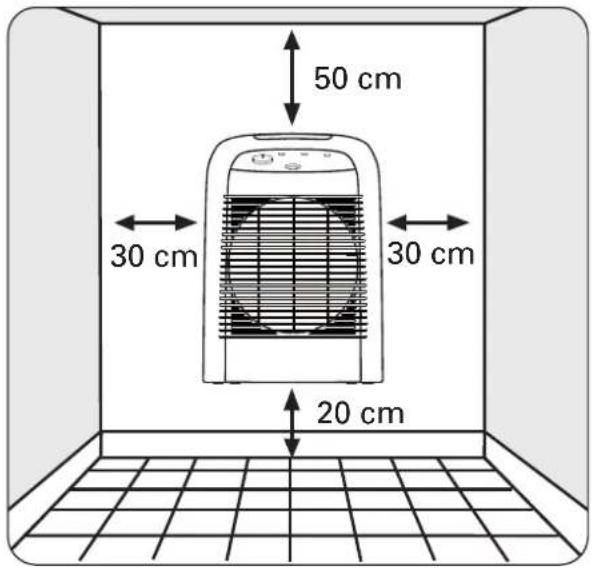

RÅD ANGÅENDE SIKKERHET OG BRUK

VEDLIKEHOLD AV APPARATET
natural_image
Line drawing of a portable electric heater inside a room with a 30 cm height dimension标注 (no text or symbols on the device itself)

SIKKERHEDSREGLER

DAEK IKKE VARMEAPPARATET TIL for at undgå overopvarming.
natural_image
Line drawing of a portable electric heater inside a room with a 30 cm height dimension标注 (no text or symbols on the device itself)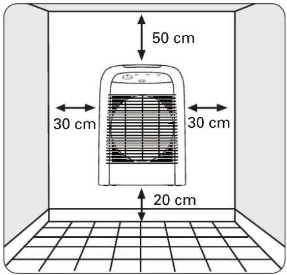
ВНИМАНИЕ

natural_image
Line drawing of a heating fan inside a room with a 30 cm height dimension标注 (no text or symbols on the fan or background)
Obr. 4a Obr. 4b


UPOZORNĚNÍ

natural_image
Line drawing of a portable electric heater inside a room with a 30 cm height dimension标注 (no text or symbols on the device itself)
Sl. 4a Sl. 4b


VAŽNE NAPOMENE

Od osnovne je važnosti pozorno pročitati ovu uputu i pratiti sljedeće preporuke:
Indikator 2: Indikator se pali čim se uređaj uključi na gumbu 1.
Gumb 3: Termostat (gumb 1 treba biti na položajili ●●).
- Temperaturu možete podešavati prema potrebi okretanjem sklopke (3).
- Položaj - temperatura iznad točke zamrzavanja * : Ovaj položaj omogućava podesiti temperaturu na stupanj viši od 0°C u sobi s normalnom termoizolacijom čije dimenzije odgovaraju kapacitetu vašeg uređaja.
MODEL SO6220 :
Kada se uređaj stavlja pod napon (uređaj priključen u utičnicu), on je u načinu rada „ISKLJUČEN“, gumb 1 svijetli. Uređaj daje zvučni signal pri svakom rukovanju upravljačkim gumbima.
Gumb 1 „STAND-BY“: Zaustavljanje uređaja (ciklus hlađenja od nekoliko sekundi se automatski odvija prije svakog zaustavljanja; tijekom tog ciklusa, gumb trepće)
natural_image
Line drawing of a portable electric heater inside a room with a 30 cm dimension label (no text or symbols on the device itself)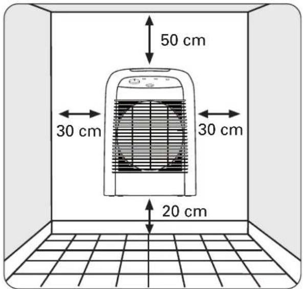
4a. ábra 4b. ábra

FONTOS TUDNIVALOK

natural_image
Line drawing of a portable electric heater inside a room with a 30 cm height dimension标注 (no text or symbols on the device itself)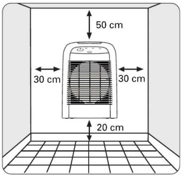
Rys. 4a Rys. 4b


WAŻNE ZALECENIA

natural_image
Line drawing of a portable electric heater inside a room with a 30 cm dimension标注 (no text or symbols on the device itself)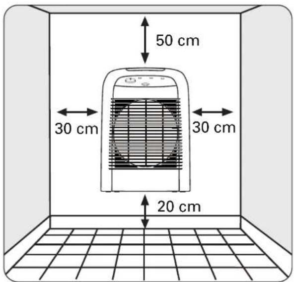
Fig. 4a Fig. 4b

ATENTIE

natural_image
Line drawing of a portable electric heater inside a room with tiled floor and 30 cm dimension label (no text or symbols on the device itself)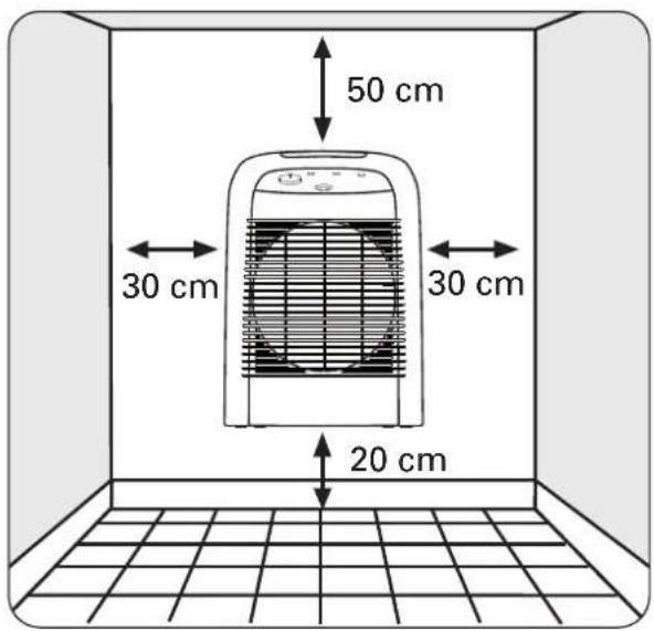
Obr. 4a Obr. 4b

UPOZORNENIA

natural_image
Line drawing of a portable electric heater inside a room with a 30 cm dimension标注 (no text or symbols on the device itself)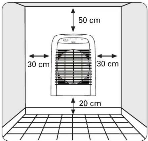
Sl. 4a Sl. 4b
POMEMBNA OPOZORILA

natural_image
Line drawing of a portable electric heater inside a room with a 30 cm height dimension标注 (no text or symbols on the device itself)

UPOZORENJA

Od osnovne je važnosti pažljivo pročitati ovo uputstvo i slijediti naredne preporuke:
natural_image
Line drawing of a heating fan inside a room with a 30 cm height dimension标注 (no text or symbols on the fan or background)

UPOZORENJA

Najvažnije je da pažljivo pročitate ovo uputstvo i da se upoznate sa sledećim savetima:
natural_image
Line drawing of a portable electric heater inside a room with a 30 cm height dimension标注 (no text or symbols on the device itself)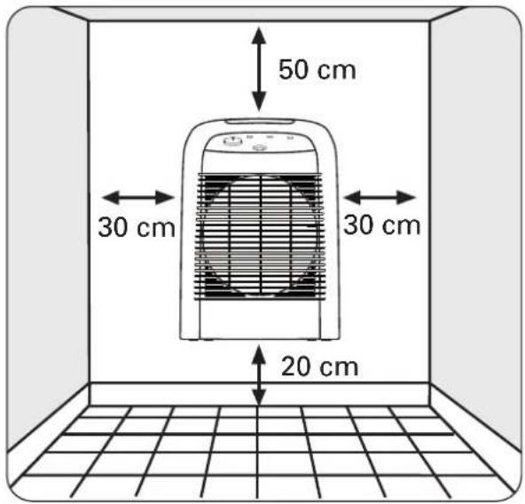


OLULINE

natural_image
Line drawing of a portable electric heater inside a room with a 30 cm dimension标注 (no text or symbols on the device itself)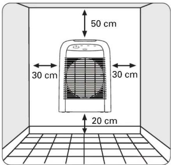

PERSPÈJIMAS

natural_image
Line drawing of a portable electric heater inside a room with a 30 cm height dimension标注 (no text or symbols on the device itself)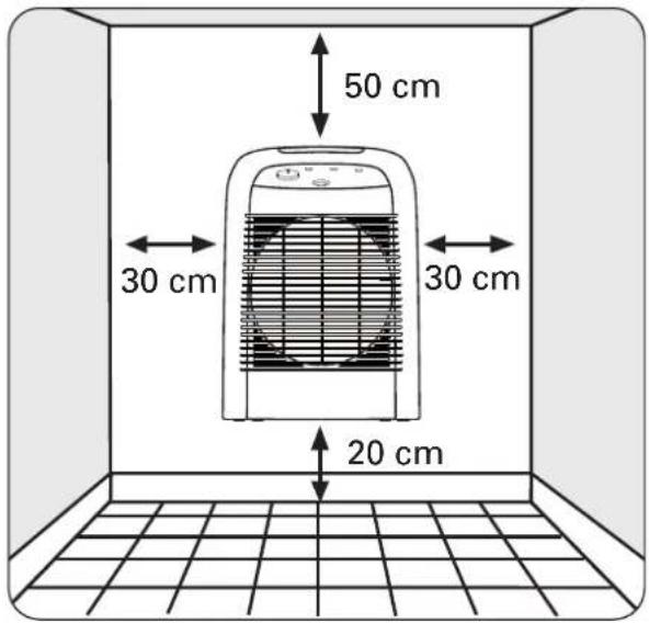
BRĪDINĀJUMI

natural_image
Line drawing of a portable electric heater inside a room with a 30 cm height dimension标注 (no text or symbols on the device itself)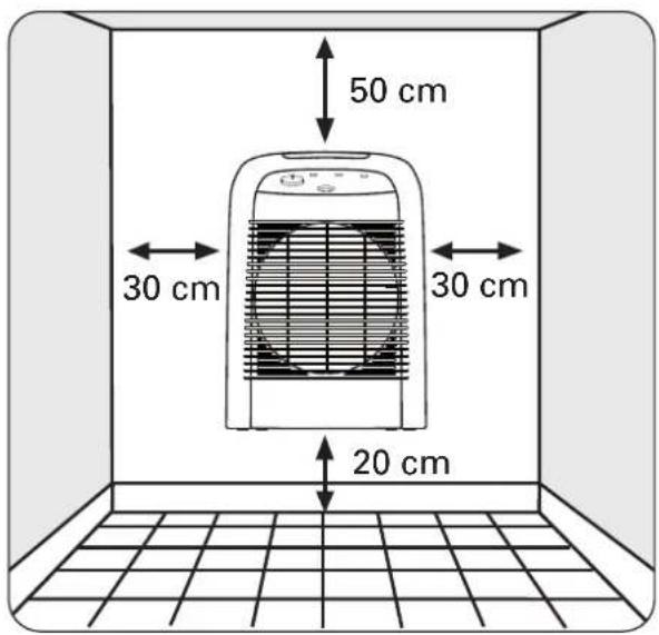
图4a 图4b


注意事项

natural_image
Line drawing of a portable electric heater inside a room with a 30 cm height dimension标注 (no text or symbols on the device itself)- وضعية " ثابت" شكل
4a شكل
natural_image
Line drawing of a portable electric heater inside a room with a 30 cm dimension标注 (no text or symbols on the device itself)- وضعیت ساکن - تصوير

4a شكل
4b شكل

- DESCRIPTIF TECHNIQUE
- F
- AVERTISSEMENTS
- WARNINGS
- USE IN THE BATHROOM (protection against splashing with water)
- WALL INSTALLATION
- SAFETY
- OPERATION
- MODEL SO6210 :
- MODEL SO6220 :
- TAKING CARE OF YOUR APPLIANCE
- STORAGE
- INTHE EVENT OF PROBLEMS
- ENVIRONMENT PROTECTION FIRST!
- BESCHREIBUNG
- D
- HINWEISE
- WAARSCHUWINGEN
- AVVERTIMENTI
- I
- ADVERTENCIAS
- E
- AVISOS
- P
- ΠΡΟΕΙΔΟΠΟΙΗΣΕΙΣ
- UYARILAR
- WARNINGAR
- S
- VAROITUKSIA
- RÅD ANGÅENDE SIKKERHET OG BRUK
- VEDLIKEHOLD AV APPARATET
- SIKKERHEDSREGLER
- ВНИМАНИЕ
- UPOZORNĚNÍ
- VAŽNE NAPOMENE
- FONTOS TUDNIVALOK
- WAŻNE ZALECENIA
- ATENTIE
- UPOZORNENIA
- POMEMBNA OPOZORILA
- UPOZORENJA
- OLULINE
- PERSPÈJIMAS
- BRĪDINĀJUMI
- 注意事项
Brand : ROWENTA
Model : Balnea Silence SO6210
Category : Heating