
BHG 1000W - Heating AEG - Free user manual and instructions
Find the device manual for free BHG 1000W AEG in PDF.
| Brand | AEG |
| Model | BHG 1000W |
| Product type | Electric wall heater for bathroom |
| Power | 1000 W |
| Power supply | 1/N ~ 230/240 V |
| Dimensions (H x W x D) | 1781 x 550 x 115 mm |
| Weight | 30 kg |
| Temperature setting range | 6 °C to 30 °C |
| Anti-freeze position | 6 °C |
| Protection rating (IP) | IP24 |
| Protection class | II |
| Color | Signal white (RAL 9016) |
| Material | Steel with coating |
| Heating type | Natural convection and radiation |
| Main functions | Room thermostat, Boost 2h, Auto 24h, Child lock |
| Operating mode | Manual (ON/OFF), Boost, Auto 24h |
| Indicator lights | Operation indicator, heating indicator |
| Included accessories | Wall mounting bracket, 2 towel hooks |
| Electrical connection | Wall socket with earth, fixed cable not allowed |
| Mounting | Wall mounting only, on a vertical wall resistant to 80 °C |
| Cleaning and maintenance | Soft cloth and usual products, avoid abrasive products |
| Warranty | Varies by country, contact local subsidiary |
| Repairability | Original spare parts recommended, qualified installer |
| Standards | Comply with national and local regulations |
Frequently Asked Questions - BHG 1000W AEG
User questions about BHG 1000W AEG
0 question about this device. Answer the ones you know or ask your own.
Ask a new question about this device
Download the instructions for your Heating in PDF format for free! Find your manual BHG 1000W - AEG and take your electronic device back in hand. On this page are published all the documents necessary for the use of your device. BHG 1000W by AEG.
USER MANUAL BHG 1000W AEG
Operation and installation 10
natural_image
Pure mechanical diagram showing a beam supported by two supports and a curved pipe with a load, without any text or symbols.26_07_80_0054

Hinweis
26_07_80_0056
- General information ...... 11
- Safety 11
- Appliance description....12
- Operation....12
- Cleaning, care and maintenance 13
- Troubleshooting 13
INSTALLATION
- Safety 13
- Appliance description....13
- Installation....13
- Power supply....14
- Troubleshooting 14
- Appliance handover 14
- Specification 15
GUARANTEE
ENVIRONMENT AND RECYCLING
SPECIAL INFORMATION
- Keep children under the age of 3 away from the appliance if constant supervision cannot be guaranteed.
Children from the age of 3 to 7 may switch the appliance on and off, provided they are supervised or have been instructed in the safe operation of the appliance and understand any risks that may result there from. This is subject to the appliance having been installed as described.
Children from the age of 3 to 7 must not plug the power cable into its socket nor regulate the appliance.
The appliance may be used by children aged 8 and up and persons with reduced physical, sensory or mental capabilities or a lack of experience and know-how, provided that they are supervised or they have been instructed on how to use the appliance safely and have understood the resulting risks.
Children must never play with the appliance. Children must never clean the appliance or perform user maintenance unless they are supervised.
- Parts of the appliance can get very hot and may cause burns.
Particular caution is advised when children or vulnerable persons are present.
- Never install the appliance directly below a wall socket.
• In the case of a permanent connection, the appliance must be able to be separated from the power supply by an isolator that disconnects all poles with at least 3 mm contact separation.
• In the event of damage to the power cable this must always be replaced by a qualified electrician authorised by the manufacturer, using original spare parts.
- Secure the appliance as described in chapter "Installation / Installation".
OPERATION
1. General information
The chapter "Operation" is intended for appliance users and qualified contractors.
The chapter "Installation" is intended for qualified contractors.

Note
Read these instructions carefully before using the appliance and retain them for future reference.
Pass on the instructions to a new user if required.
1.1 Safety instructions
1.1.1 Structure of safety instructions

KEYWORD Type of risk
Here, possible consequences are listed that may result from failure to observe the safety instructions.
» Steps to prevent the risk are listed.
1.1.2 Symbols, type of risk
Symbol Type of risk
| Injury | |
| Electrocution | |
| Burns(burns, scalding) |
1.1.3 Keywords
| KEYWORD | Meaning |
| DANGER | Failure to observe this information will result in serious injury or death. |
| WARNING | Failure to observe this information may result in serious injury or death. |
| CAUTION | Failure to observe this information may result in non-serious or minor injury. |
1.2 Other symbols in this documentation

Note
General information is identified by the symbol shown on the left.
» Read these texts carefully.
Symbol Meaning
| Material losses(appliance damage, consequential losses and environmental pollution) | |
| Appliance disposal |
» This symbol indicates that you have to do something.
The action you need to take is described step by step.
1.3 Units of measurement

Note
All measurements are given in mm unless stated otherwise.
2. Safety
2.1 Intended use
The appliance is an electric direct heater for installation on a wall.
This appliance has been designed as a booster heater for use between seasons. It is particularly suitable for bathrooms and drying bathrobes and towels.
This appliance is intended for domestic use. It can be used safely by untrained persons. The appliance can also be used in a non-domestic environment, e.g. in a small business, as long as it is used in the same way.
Any other use beyond that described shall be deemed inappropriate. Observation of these instructions and of instructions for any accessories used is also part of the correct use of this appliance.
2.2 General safety instructions

WARNING Injury
- Keep children under the age of 3 away from the appliance if constant supervision cannot be guaranteed.
Children from the age of 3 to 7 may switch the appliance on and off, provided they are supervised or have been instructed in the safe operation of the appliance and understand any risks that may result there from. This is subject to the appliance having been installed as described. Children from the age of 3 to 7 must not plug the power cable into its socket nor regulate the appliance.
The appliance may be used by children aged 8 and up and persons with reduced physical, sensory or mental capabilities or a lack of experience and know-how, provided that they are supervised or they have been instructed on how to use the appliance safely and have understood the resulting risks.
Children must never play with the appliance. Children must never clean the appliance or perform user maintenance unless they are supervised.

CAUTION Burns
Parts of the appliance can get very hot and may cause burns. Particular caution is advised when children or vulnerable persons are present.

Note
Operate the appliance only when fully installed and with all safety equipment fitted.
3. Appliance description
This appliance has been designed as a booster heater and is particularly suitable for bathrooms, as well as drying and warming bathrobes and towels. You can place your towels at various heights.
The appliance heats the room through natural convection and radiated warmth. The integral room thermostat keeps the room at the set temperature. For this, it is important that the appliance's heating output matches the room's heat demand. This only applies if no towels or bathrobes are hung on the appliance.
The boost function enables the appliance to be operated at full heating output without temperature control for a limited period of 2 hours. You can program the time at which the appliance starts automatically every day.
The appliance is ready for operation when it has been fixed to the wall and plugged into the mains.
4. Operation
4.1 User interface description
You operate the appliance by means of its user interface.

1 ON/OFF indicator
2 Heat indicator
3 Temperature selector
4 "24h auto" setting range
5 Rotary selector
4.2 Switching the appliance on
» Set the mode selector to "ON".
» Set the required room temperature with the temperature selector. You can choose between 10 °C and 30 °C.
The heat indicator lights up when the appliance starts to heat. The heat indicator goes off when the temperature set at the temperature selector is reached.

Note
If several appliances are installed in one room, a different temperature can be set at each one.

Note
To avoid excessive power consumption when windows are open, stop the appliance while venting.
4.3 2 h boost function
Enable
» Switch the appliance on.
» Press the mode selector for about a second.
The ON/OFF indicator and the heat indicator illuminate. The appliance heats for 2 hours at full output.
At the end of the 2 hours, the appliance returns to standard operation with the temperature selector. The heat indicator and ON/OFF indicator extinguish.
Disable
» Press the mode selector for about a second.
The heat indicator and ON/OFF indicator extinguish. The appliance returns to normal operation controlled by the temperature selector.
4.4 24 h automatic function
The 24 h automatic function repeats the 2 h boost function automatically every 24 hours.
Enable
Turn the mode selector fully clockwise to "24 h auto".
The ON/OFF indicator and the heat indicator illuminate. The appliance heats for 2 hours at full output.
At the end of the 2 hours, the appliance returns to standard operation with the temperature selector. The heat indicator and ON/OFF indicator extinguish.
The 2h boost function starts the following day 45 minutes before the time when the appliance was set to "24h auto".
Example:
You would like your bathroom to be at the required temperature at 07:00 h in the morning.
» On the first day at 07:00 h in the morning, set the rotary selector to "24h auto".
The appliance immediately starts heating as per the 2 h boost function. The next day, the 2h boost function automatically starts at 06:15 h in the morning, in order to heat up the bathroom for 07:00 h.
Interruption
You can interrupt the 2 h boost function at any time without changing the start time.
» Press the mode selector for about a second.
The heat indicator and ON/OFF indicator extinguish. The appliance returns to normal operation controlled by the temperature selector.
On the following day the 2 h boost function will resume from the usual start time.
Disable
» Turn the mode selector fully anti-clockwise to "ON".
The heat indicator and ON/OFF indicator extinguish. The appliance returns to normal operation controlled by the temperature selector.
4.5 Childproofing
This function prevents the temperature setting from being changed unintentionally.
If the childproof setting is active, the temperature and mode selectors are not operational. The ON/OFF indicator flashes if you adjust the mode selector/temperature selector.
Enable
» Press and hold the mode selector for more than three seconds.
The ON/OFF indicator flashes consecutively five times. This tells you that the childproof setting is active.
You can also use the 2 h boost function as usual when childproofing has been enabled.
Disable
» Press and hold the mode selector for more than three seconds.
The ON/OFF indicator flashes consecutively five times. This tells you that the childproof setting is disabled.
4.6 Shutting down the system
» Stop the appliance by turning the rotary selector to "OFF".
The ON indicator goes off.
» Pull the mains plug out of the wall socket.
5. Cleaning, care and maintenance
Clean the surfaces when cold with a soft cloth and ordinary cleaning products.

Note
Avoid abrasive or corrosive cleaning products.
6. Troubleshooting
6.1 Fault table
| Fault Cause Remedy | ||
| The heated air smells unpleasant. | This can be caused by dust during commissioning. | The smell will dissipate within a few minutes. |
| The appliance does not heat up. | The MCB/fuse has responded/blown. | Replace the fuse/reset the MCB. |
| The appliance heats continuously. | The appliance is subject to a continuous draught. | Remedy the cause of the draught. |
| The temperature setting was changed. | Set the required room temperature at the temperature selector. | |
| There is a fault with the power supply. | Disconnect the appliance from the power supply for 10 minutes and then switch it back on. If the problem occurs regularly, arrange for your power supply utility to check the power supply. | |
| The 24 h automatic function is not performed. | There was a power failure. | Set the 24 h automatic function again. |
| The setting at the operating mode selector was changed. | Set the 24 h automatic function again. | |
| The clocks have changed to summer/wintertime. | Set the 24 h automatic function again. | |
| The elements at the very top and bottom don't get as warm as the rest of the appliance. | The elements at the top have not completely filled. | The heating medium expands when it gets warm. It takes a little longer for these elements to heat up. |
| Dirty marks appear on the wall around the appliance. | Dirty marks are caused by contaminated air from the interior (candles, cigarette smoke, poor ventilation etc.). | Remedy the cause of any air contamination. |
If you cannot remedy the fault, notify your qualified contractor. To facilitate and speed up your request, provide the number from the type plate (000000-0000-000000). The type plate is located underneath the appliance on the right hand side.
INSTALLATION
7. Safety
Only a qualified contractor should carry out installation, commissioning, maintenance and repair of the appliance.
7.1 General safety instructions
We guarantee trouble-free function and operational reliability only if original accessories and spare parts intended for the appliance are used.
7.2 Instructions, standards and regulations

Note
Observe all applicable national and regional regulations and instructions.
8. Appliance description
8.1 Standard delivery
- Wall mounting bracket with fixing materials
- 2 bathrobe hooks
The appliance is delivered fully wired.
9. Installation
9.1 Installation site

Material losses
Observe the minimum clearances in chapter "Specification".

Material losses
Fit the appliance to a vertical wall that is temperature-resistant to at least 80 °C.

Material losses
Never install the appliance directly below a wall socket.
9.2 Wall mounting

Note
Observe the dimensions and minimum clearances in chapter "Specification".
» Drill the holes and insert rawl plugs.
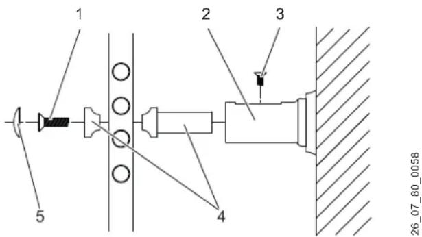
1 Retainer screw
2 Wall sleeve
3 Lock screw
4 Retainer
5 Cap
natural_image
Pure mechanical diagram showing a beam supported by two supports and a curved pipe with a spring, without any text or symbols.26_07_80_0054

Note
Note the alignment of the wall sleeves.
» Use screws to secure the wall sleeves.
» Secure the retainers to the rungs. Do not yet tighten the retainers.

natural_image
Pure mechanical diagram showing two screwdrivers and a vertical support structure without any text or symbols26 07 80 0056
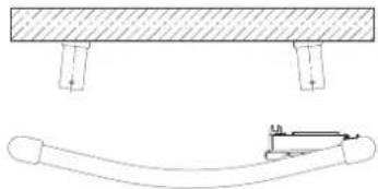
» Fit the wall mounting bracket. For this, observe the slot position. The slot must point respectively up or down.

» Assemble the appliance and wall mounting bracket.
» Insert and tighten the screws to secure the appliance.
9.3 Fitting the bathrobe hooks

26 07 80 0055
1 Bathrobe hook
2 Washer
3 Bathrobe hook backplate
» Fit the bathrobe hooks as shown.
10. Power supply

WARNING Electrocution
In wet rooms such as shower rooms and kitchens, install the flush box at least 25 cm above the floor.

WARNING Electrocution
Never operate the appliance with an extension cable or a multiple socket.

Material losses
Ensure the appliance can be separated from the power supply by an isolator that disconnects all poles with at least 3 mm contact separation. For this, use contactors, mains isolators, fuses, etc. Installation with a permanent power cable is not permitted.

Material losses
Observe the type plate. The specified voltage must match the mains voltage.

Note
Carry out all electrical connection and installation work in accordance with national and regional regulations.

Note
Ensure a standard socket or junction box for a permanent power supply is installed at a distance of at least 10 cm from the side of the appliance.
11. Troubleshooting
The power cable must only be replaced by a qualified contractor using original spare parts.
12. Appliance handover
» Explain the functions of the appliance to the user.
» Draw special attention to the safety instructions.
» Pass on the operating and installation instructions to the user.
13. Specification
13.1 Dimensions

D0000026162
| BHG | 500 W | BHG 750 W | BHG 750 C | BHG 1000 W | |||
| a10 | Appliance | Height | mm | 998 | 1453 | 1658 | 1781 |
| a20 | Appliance | Width | mm | 480 | 480 | 600 | 550 |
| a30 | Appliance | Depth | mm | 100 | 115 | 110 | 115 |
| i13 | Wall mounting bracket | Hole spacing vertical | mm | 779 | 1230 | 1435 | 1599 |
| Hole spacing horizontal | mm | 350 | 350 | 450 | 400 | ||
13.2 Minimum clearances

D0000026163
13.3 Data table
| BHG 500 W | BHG 750 W | BHG 750 C | BHG 1000 W | ||
| 236572 | 231950 | 231951 | 233861 | ||
| Electrical details | |||||
| Power supply | 1/N ~ 230/240 V | 1/N ~ 230/240 V | 1/N ~ 230/240 V | 1/N ~ 230/240 V | |
| Connected load | kW | 0,5 | 0,75 | 0,75 | 1,0 |
| Dimensions | |||||
| Height | mm | 998 | 1453 | 1658 | 1781 |
| Width | mm | 480 | 480 | 600 | 550 |
| Depth | mm | 100 | 115 | 110 | 115 |
| Weights | |||||
| Weight | kg | 12 | 16 | 24 | 30 |
| Versions | |||||
| Frost protection setting | °C | 6 | 6 | 6 | 6 |
| IP-Rating | IP24 | IP24 | IP24 | IP24 | |
| Protection class | II | II | II | II | |
| Colour | commercial white, RAL 9016 | commercial white, RAL 9016 | Chrome | commercial white, RAL 9016 | |
| Values | |||||
| Setting range | °C | 6-30 | 6-30 | 6-30 | 6-30 |
| BHG 500 W | BHG 750 W | BHG 750 C | BHG 1000 W | ||
| 236572 | 231950 | 231951 | 233861 |
| Electrical details | |||||
| Power supply | 1/N ~ 230/240 V | 1/N ~ 230/240 V | 1/N ~ 230/240 V | 1/N ~ 230/240 V | |
| Connected load | kW | 0,5 | 0,75 | 0,75 | 1,0 |
| Dimensions | |||||
| Height | mm | 998 | 1453 | 1658 | 1781 |
| Width | mm | 480 | 480 | 600 | 550 |
| Depth | mm | 100 | 115 | 110 | 115 |
| Weights | |||||
| Weight | kg | 12 | 16 | 24 | 30 |
| Versions | |||||
| Frost protection setting | °C | 6 | 6 | 6 | 6 |
| IP-Rating | IP24 | IP24 | IP24 | IP24 | |
| Protection class | II | II | II | II | |
| Colour | commercial white, RAL 9016 | commercial white, RAL 9016 | Chrome | commercial white, RAL 9016 | |
| Values | |||||
| Setting range | °C | 6-30 | 6-30 | 6-30 | 6-30 |
Guarantee
The guarantee conditions of our German companies do not apply to appliances acquired outside of Germany. In countries where our subsidiaries sell our products a guarantee can only be issued by those subsidiaries. Such guarantee is only granted if the subsidiary has issued its own terms of guarantee. No other guarantee will be granted.
We shall not provide any guarantee for appliances acquired in countries where we have no subsidiary to sell our products. This will not affect warranties issued by any importers.
Environment and recycling
We would ask you to help protect the environment. After use, dispose of the various materials in accordance with national regulations.
REMARQUES PARTICULIÈRES
UTILISATION
natural_image
Pure mechanical diagram showing a beam supported by two supports and a curved pipe with a spring, without any text or symbols.26_07_80_0054

Remarque
natural_image
Pure mechanical diagram showing two screwdrivers and a vertical support structure without any text or symbols26_07_80_0056
natural_image
Pure mechanical diagram showing a beam supported by two supports and a curved pipe with a spring, without any text or symbols.26_07_80_0054

Info
natural_image
Pure mechanical diagram showing two screwdrivers and a vertical support structure without any text or symbols26 07 80 0056
26 07 80 0055
natural_image
Pure mechanical diagram showing a beam supported by two supports and a curved pipe with a spring, without any text or symbols.26_07_80_0054

natural_image
Pure mechanical diagram showing two screwdrivers and a vertical support structure without any text or symbols26 07 80 0056
natural_image
Pure mechanical diagram showing a beam supported at the top and a curved pipe with a spring attached (no text or symbols)26_07_80_0054

Указание
natural_image
Pure mechanical diagram showing two screwdrivers and a vertical component mounted on a wall, without any text or symbols.26_07_80_0056
natural_image
Technical line drawing of a mechanical assembly with three views (top, front, side) showing structural components and mounting points (no text or symbols)natural_image
Technical diagram showing a beam supported at the top and a curved pipe with a small inset detail (no text or symbols)26_07_80_0054
Urzhumskaya street 4,
building 2
129343 Moscow
Tel. 0495 7753889
Fax 0495 7753887
Switzerland
STIEBEL ELTRON AG
Industrie West
Gass 8
5242 Lupfig
Tel. 056 4640-500
Fax 056 4640-501


- Hinweis
- INSTALLATION
- GUARANTEE
- ENVIRONMENT AND RECYCLING
- SPECIAL INFORMATION
- OPERATION
- General information
- Safety instructions
- Structure of safety instructions
- Symbols, type of risk
- Keywords
- Other symbols in this documentation
- Units of measurement
- Safety
- Intended use
- General safety instructions
- Appliance description
- Operation
- User interface description
- Switching the appliance on
- Note
- 2 h boost function
- Enable
- Disable
- 24 h automatic function
- Example:
- Interruption
- Childproofing
- Shutting down the system
- Cleaning, care and maintenance
- Troubleshooting
- Safety
- General safety instructions
- Instructions, standards and regulations
- Appliance description
- Standard delivery
- Installation
- Installation site
- Wall mounting
- Note the alignment of the wall sleeves.
- Fitting the bathrobe hooks
- Power supply
- WARNING Electrocution
- Material losses
- Troubleshooting
- Appliance handover
- Specification
- Dimensions
- Minimum clearances
- Data table
- REMARQUES PARTICULIÈRES
- UTILISATION
- Remarque
- Info
- Указание
- Switzerland
Brand : AEG
Model : BHG 1000W
Category : Heating