
PH 960 MST GH - Cooker Ariston Thermo - Free user manual and instructions
Find the device manual for free PH 960 MST GH Ariston Thermo in PDF.
| Product type | Mixed gas and electric cooker with ceramic hob and grill plate |
| Brand | Ariston Thermo |
| Model | PH 960 MST GH |
| Gas burners | 5 burners (1 Rapid, 1 Rapid Reduced, 1 Semi-rapid, 1 Auxiliary, 1 Triple crown, 1 Semi-fish) |
| Electric plates | 2 normal/rapid plates (depending on model) |
| Ceramic zone | With dual burner (circular and extendable) and residual heat indicator |
| Grill plate | Integrated with electric heating element and grease collection tray |
| Gas supply | Natural gas (G20/G25) or LPG (butane/propane) – adaptable |
| Power supply | 220-240 V ~ 50/60 Hz |
| Total gas power | Approximately 12 kW (depending on burners) |
| Total electric power | Approximately 6 kW (plates + grill + ceramic) |
| Dimensions (W x D x H) | 60 x 60 x 10 cm (built-in) |
| Weight | Approximately 55 kg |
| Safety | Safety device (thermocouple) on burners, residual heat indicator on ceramic hob |
| Maintenance and cleaning | Clean with damp cloth, non-abrasive products, scraper for ceramic hob, tap lubrication by a professional |
| Spare parts and repairability | Replacement injectors, fixing hooks, seals – available at authorized after-sales service |
| Conformity | Directives 73/23/EEC, 89/336/EEC, 90/396/EEC, 93/68/EEC, 2002/96/EC |
Frequently Asked Questions - PH 960 MST GH Ariston Thermo
User questions about PH 960 MST GH Ariston Thermo
0 question about this device. Answer the ones you know or ask your own.
Ask a new question about this device
Download the instructions for your Cooker in PDF format for free! Find your manual PH 960 MST GH - Ariston Thermo and take your electronic device back in hand. On this page are published all the documents necessary for the use of your device. PH 960 MST GH by Ariston Thermo.
USER MANUAL PH 960 MST GH Ariston Thermo
Importante: Anything applicable to the use of this material should be carefully checked before use.
Congratualtions on choosing an Ariston appliance, which you will find is dependable and easy to use. We recommend that you read this manual for best performance and to extend the life of your appliance. Thank you.
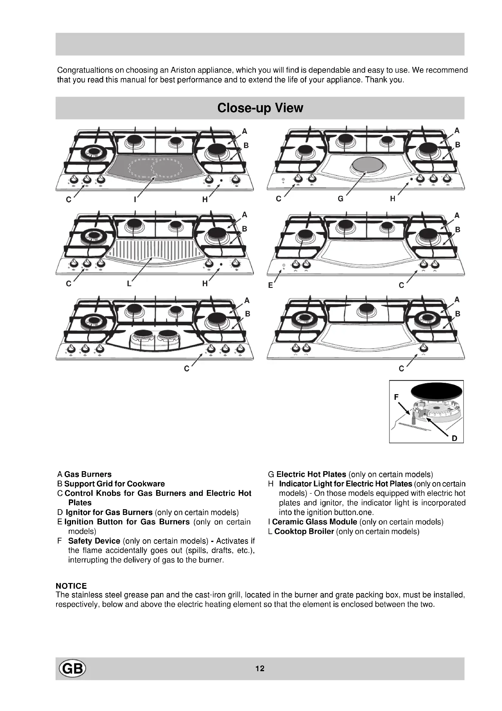
Close-up View
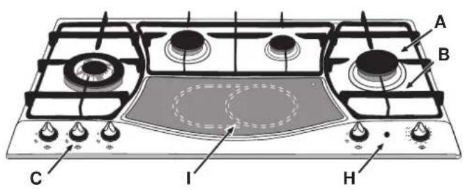
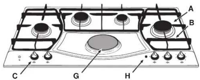
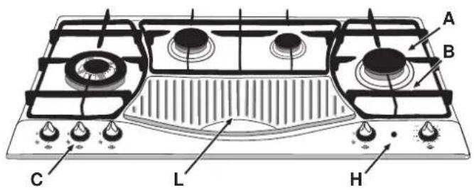
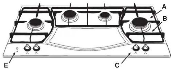
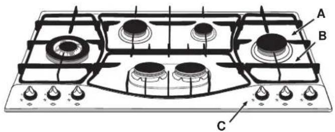
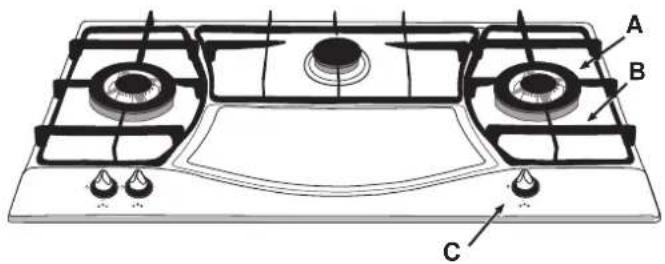
A Gas Burners
B Support Grid for Cookware
C Control Knobs for Gas Burners and Electric Hot Plates
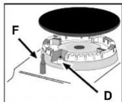
D Ignitor for Gas Burners (only on certain models)
E Ignition Button for Gas Burners (only on certain models)
F Safety Device (only on certain models) - Activates if the flame accidentally goes out (spills, drafts, etc.), interrupting the delivery of gas to the burner.
NOTICE
The stainless steel grease pan and the cast-iron grill, located in the burner and grate packing box, must be installed, respectively, below and above the electric heating element so that the element is enclosed between the two.
G Electric Hot Plates (only on certain models)
H Indicator Light for Electric Hot Plates (only on certain models) - On those models equipped with electric hot plates and ignitor, the indicator light is incorporated into the ignition button. one.
I Ceramic Glass Module (only on certain models)
Cooktop Broiler (only on certain models)
How To Use Your Appliance
The position of the corresponding gas burner or electric hot plate (if present) is indicated on each control knob.
Gas Burners
The burners differ in size and power. Choose the most appropriate one for the diameter of the cookware being used.
The burner can be regulated with the corresponding control knob by using one of the following settings:
- Off
High Low
To turn on one of the burners, place a lighted match or lighter near the burner, press the knob all the way in and turn in the counter-clockwise direction to the "High" setting.
On those models fitted with a safety device (F), the knob must be pressed in for about 6 seconds until the device that keeps the flame lighted warms up.
On those models fitted with an ignitor (D), the "E" ignition button, identified by the symbol, must first be pressed and then the corresponding knob pushed all the way in and turned in the counter-clockwise direction to the "High" setting.
Some models are equipped with an ignition switch incorporated into the control knob. If this is the case, the ignitor (D) is present, but not the "E" switch (the symbol is located near each knob).
To light a burner, simply press the corresponding knob all the way in and then turn it in the counter-clockwise direction to the "High" setting, keeping it pressed in until the burner lights.
Caution: If the burner accidentally goes out, turn off the gas with the control knob and try to light it again after waiting at least 1 minute.
To turn off a burner, turn the knob in the clockwise direction until it stops (it should be on the “·” setting).
Electric Hot Plates (only on certain models)
The hot plates vary in diameter and power: "normal" and "fast". The latter can be identified by a red boss in the center of the hot plate itself.
The hot plate can be regulated by turning the corresponding knob in the clockwise or counter-clockwise direction to any one of the 6 different settings:
0 Off
1 Low
2-5 Medium
6 High
The section entitled, "Practical Cooking Advise", provides information on the recommended settings for various types of food or cooking processes.
When the knob is on any of the settings other than "Off", the "H" operating light comes on.
Cooktop Broiler (only on certain models)
The broiler can be regulated by turning the corresponding knob in the clockwise or counter-clockwise direction to any of the 12 possible settings:
0Off
1 Low
2-11 Medium
12 High
When the knob is on any of the settings other than "Off", the "H" operating light comes on.
Ceramic Glass Module (only on certain models)
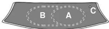
This cooktop is fitted with dual-ring radiant heating elements located beneath the glass. It is possible to turn on only the circular part of the element (identified by the letter "A") or the cooking surface can be enlarged by turning on both "A" and "B". To turn only the circular "A" element, simply turn the knob in the clockwise direction to any one of the 12 available settings. To add the "B" section, turn the knob to setting 12 and then click it into the setting. Then proceed by turning the knob in the counter-clockwise direction to one of the 12 settings.
The figure shows the heating zones, which become red when the element is turned on.
A. Circular heating zone;
B. Extended heating zone;
C. Indicator light to show when the cooking zone is above 60^ , even after the heating element has been turned off.
When the knob is on any of the settings other than "Off", the "H" operating light comes on.
How to Keep Your Cooktop in Shape
Before cleaning or performing maintenance on your appliance, disconnect it from the electrical power supply.
To extend the life of the cooktop, it is absolutely indispensable that it be cleaned carefully and thoroughly on a frequent basis, keeping in mind the following:
- Do not use steam equipment to clean the appliance.
- The enameled parts and the glass top, if present, must be washed with warm water without using abrasive powders or corrosive substances which could ruin
them;
- The removable parts of the burners should be washed frequently with warm water and soap, making sure to remove caked-on substances;
- On cooktops with automatic ignition, the end of the electronic ignition device must be cleaned carefully and frequently, making sure that the gas holes are not clogged;
-
The electric hobs should be cleaned using a damp cloth and then rubbed with oil while still warm;
-
Stainless steel can be stained if it remains in contact with highly calcareous water or aggressive detergents (containing phosphorous) for an extended period of time. It is recommended that these parts be rinsed thoroughly with water and then dried well. It is also a good idea to clean up any spills;
- Before using the ceramic glass module, the surface must be cleaned, using a damp cloth to remove dust or food residues. The ceramic glass surface should be cleaned regularly with a solution of warm water and a non-abrasive detergent. Periodically, special products will need to be used to clean the surface. First, remove all food buildup or grease with a cleaning scraper, e.g. CERA (not supplied) (Fig. A).
Clean the cooking surface when it is still warm with a suitable cleaning product and paper towels. Then rub with a damp cloth and dry. Aluminum foil, plastic items, objects made of synthetic material, sugar or foods with a high sugar content that have melted onto the surface must be removed immediatley with a scraper while the cooking surface is still hot. Special cleaning products for ceramic glass surfaces form a transparent protective layer which fights dirty buildup. This also protects the surface from damage caused by food with a high sugar content. Do not use abrasive sponges or cleaning products under any circumstances. This holds true for chemically aggressive cleaners, like oven sprays and stain removers (Fig. B);
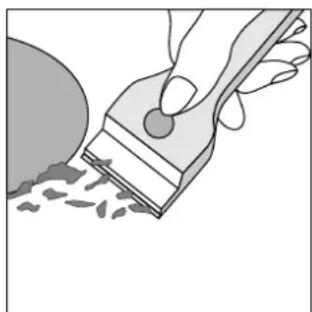
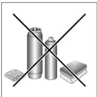
Fig.A Fig.B
- When cleaning the grill, it is recommended that you do so while it is still hot, using the handles provided to move it from the cooktop to the sink. To remove the pan beneath the grill, it is a good idea to wait until the heating element has cooled (roughly after 15 minutes).
Greasing the Taps
The taps may jam in time or they may become difficult to turn. If so, the tap itself must be replaced.
N.B.: This operation must be performed by a technician authorised by the manufacturer.
Practical Advice
Practical Advise on Using the Burners
For best performance, follow these general guidelines:
- Use the appropriate cookware for each burner (see table) in order to prevent the flame from reaching the sides of the pot or pan;
- Alwasy use cookware with a flat bottom and keep the lid on;
- When the contents come to a boil, turn the knob to "Low".
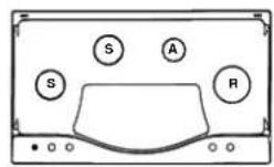
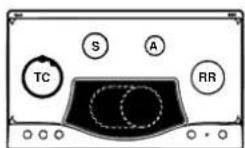
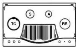
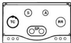
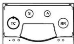
| Burner ø Cookware diameter (cm) |
| Fast (R) 24 - 26 |
| Reduced Fast (RR) 24 - 26 |
| Semi Fast (S) 16 - 20 |
| Auxiliary (A) 10 - 14 |
| Semi-Fischburner (SP) 16 - 20 |
| Triple Crown (TC) 24 - 26 |
To identify the type of burner, refer to the designs in the section entitled, "Burner and Nozzle Specifications".
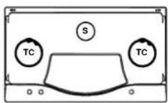
Practical Advice on Using the Half Fish-Kettle Burner
The two central burners, or Half Fish-Kettle burners, are elliptic in form and can be turned up to 90^ . This makes the cooktop more flexible in terms of how it can be used.
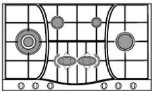
To turn the two central burners 90^ , proceed as follows:
Make sure that the burners are cool;
- Lift the burner completely out of its housing;
- Replace it in its housing in the position desired;
- Make sure that the burners are positioned correctly before use.
In addition, the two cetnral burners can be used in tandem or speartely with cookware of different shapes and sizes:
- Double burner for a fish-kettle or oval cookware (Fig. A).
- Double burner for a griddle or rectangular/square cookware with minimum dimensions of 28 × 28 cm (Fig. B)
- Double burner for large cookware (diameter of 26-28 cm) (Fig. C).
- Single burner for medium size cookware (diameter of 16 - 20cm ) (Fig. D).
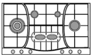
Fig. A
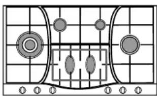
Fig.B
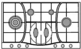
Fig. C
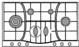
Fig. D
Practical Advice on Using the Electric Hot Plates
In order to avoid heat loss and damage to the hot plate, use cookware with a flat bottom the diameter of which is not less than that of the hot plate.
| Setting | Normal or Fast Plate |
| 0 Off | |
| 1 Cooking vegetables, fish | |
| 2 | Cooking potatoes (using steam) soups, chickpeas, beans. |
| 3 | Continuing the cooking of large quantities of food, minestrone |
| 4 | For roasting (average) |
| 5 For roasting (above average) | |
| 6 | For browning and reaching a boil in a short time. |
Before using the hot plates for the first time, you should heat them at maximum temperature for approximately 4 minutes, without any pans. During this initial stage, their protective coating hardens and reaches its maximum resistance.
Practical Advise on Using the Broiler
Preheat the broiler by turning the knob to 12. Settings 1-8 are recommended for reheating food or for keeping it warm after it has been cooked. In general, cooking vegetables can cause stains which are difficult to remove.
| Food | Weight (kg) | Knob Setting | Preheati- ng (min.) | Cooking Time (min.) |
| PorkChops | 0.5 | 12 | 5 | 15 |
| 10 20 | ||||
| Steak 0.6 12 5 | 10 | |||
| Sausages 0.45 | 10 5 20 | |||
| Shish Kabobs (meat) | 0.4 12 | 5 14 | ||
| Hamburgers 0.4 | 10 5 15 | |||
| Toasted Sandwiches | No. 3 1 | 5 2 | ||
| Bread | 3 Slices | 11 5 3 | ||
| Aubergines | 3 Slices | 12 5 | 5 + 7 | |
| Oven-roasted Tomatoes | No. 4 1 | 2 5 | 10 - 15 | |
Practical Advise on Using the Ceramic Glass Module
| Set. | Radiant Burner |
| 0 | Off |
| 1 | To melt butter and chocolate. |
| 2 | |
| 3 | To heat liquids. |
| 4 | For creams and sauces. |
| 5 | |
| 6 | For cooking at the boiling point. |
| 7 | |
| 8 | For roasts. |
| 9 | |
| 10 | For boiling large pieces of meat. |
| 11 | |
| 12 | For frying. |
| For utilising both cooking areas. |
For best performance, keep in mind the following:
- All types of cassetoles can be used on the ceramic glass cooking surface. However, it is important that the bottom be perfectly flat. Cassetoles with thicker bottoms distribute heat more evenly.

- Use cookware the diameter of which is at least as large as the cooking area so that all of the heat produced by the heating element is used.

- Make sure that the bottom of the pot is always dry and clean to insure good contact between the cookware and the cooking surface. This will also increase the life of the pots and of the ceramic glass surface as well.
- Do not use the same cookware that you use for gas burners because the concentrated heat they produce can deform the bottom of the pot. Therefore, you will not achieve best results when using these pots on the ceramic glass surface.
Notice: The glue used to seal the glass surface may leave traces on the appliance. We recommend that the module be cleaned with a non-abrasive cleaner before being used the first time. During the first few hours of use, you may detect the smell of rubber; this will disappear after a short time.
Is there a problem?
It may occur that the cooktop does not function or does not function properly. Before calling customer service for assistance, lets see what can be done.
First of all, check to see that there are no interruptions in the gas and electrical supplies, and, in particular, that the gas valves for the mains are open.
The burner does not light or the flame is not uniform around the burner.
Check to make sure that:
- The gas holes on the burner are not clogged;
- All of the movable parts that make up the burner are mounted correctly;
- There are no draughts around the cooking surface.
The flame does not stay lighted on the model with the safety device.
Check to make sure that:
- You press the knob all the way in;
- You keep the knob pressed in long enough to activate the safety device.
- The gas holes are not clogged in the area corresponding to the safety device.
The burner does not remain on when set to "Low".
Check to make sure that:
- The gas holes are not clogged.
- There are no draughts near the cooking surface.
- The minimum has been adjusted correctly (see the section entitled, "Minimum Regulation").
The cookware is not stable.
Check to make sure that:
- The bottom of the cookware is perfectly flat.
- The cookware is centered correctly on the burner or electric hot plate.
- The support grids have not been inverted.
If, despite all of these checks, the cooktop does not function properly and problem persists, call the nearest Merloni Elettrodomestici Customer Service Centre, informing them of:
- The type of problem.
- The abbreviation used to identify the model (Mod. ...) as indicated on the warranty.
Never call upon technicians not authorized by the manufacturer, and refuse to accept spare parts that are not original.
Safety Is a Good Habit to Get Into
To maintain the EFFICIENCY and SAFETY of this appliance, we recommend:
- call only the Service Centers authorized by the manufacturer
-
always use original Spare Parts
-
This manual is for a class 3 built-in cooktop.
- This appliance is designed for non-professional use in the home and its features and technical characteristics must not be modified.
These instructions are only valid for the countries the symbols for which appear on the manual and the serial plate. - The electrical system of this appliance is safe only when it is correctly connected to an adequate earthing system, as required by current safety standards.
Prevent children and the disabled from coming into contact or having access to the following, as they are possible sources of danger:
- The controls and the appliance in general;
- The packaging (plastic bags, polystyrene, nails, etc.);
- The appliance, during and immediately after use given the heat generated by its use;
- The ceramic glass cooking surface (if present) immediately before and after use, as the cooking surface will remain hot for at least a half hour after being turned off;
- The appliance when no longer in installed (in this case, all potentially dangerous parts must be made safe).
The following should be avoided:
- Touching the appliance with wet parts of the body;
- Using the appliance with bare feet;
- Pulling on the appliance or the power supply cord to disconnect them from the electrical outlet;
- Improper and/or dangerous use;
- Obstructing the ventilation or heat dissipation slots;
- Allowing the power supply cord of small appliances to come into contact with the hot parts of the cooktop;
- Exposure to atmospheric agents (rain, sun);
- Using flammable liquids nearby;
- Using adaptors, multiple outlet plugs and/or extensions;
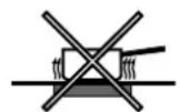
- Using unstable or deformed cookware;
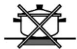
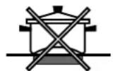
- Leaving the electric hobs on (or the ceramic glass cooking surface) without cookware on top of them;
- Using the ceramic glass cooking surface (if present) as a counter top;
-
Turning on the radiant heating elements (if present) when there is aluminum foil or plastic objects on the ceramic glass surface;
-
Striking the ceramic glass cooking surface (if present) with pointed objects;
- Closing the glass top (if present) while the gas burners or electrical hot plates are still hot;
- Trying to install or repair the appliance without the assistance of qualified personnel.
The assistance of qualified personnel must be called upon in the following cases:
- Installation (in accordance with the manufacturer's instructions);
- When in doubt about the operation of the appliance;
- Replacement of the electrical outlet because it is incompatible with the plug.
Contact service centers authorized by the manufacturer in the following cases:
When in doubt about the condition of the appliance after having removed the packing;
- Damage to or replacement of the power supply cord;
- In the case of a breakdown or malfunction: ask for original spare parts.
- In the event the ceramic glass cooking surface breaks.
It is recommended that you follow the guidelines below:
- Only use the appliance to cook food, avoiding all other uses;
- Check the condition of the appliance after it has been unpacked;
- Disconnect the appliance from the power supply in the event of malfunction and always before cleaning or maintenance;
- When not in use, disconnect the appliance from the power supply and turn off the gas valve (if present);
- Disconnect the appliance from the electrical supply in the event the ceramic glass cooking surface breakds.
- Always check to make sure that the control knobs are on the “·”/“.” setting when the appliance is not in use;
- Cut the power supply cord after disconnecting it from the electrical mains when you decide to no longer use the appliance.
- The manufacturer will not be held liable for any damages arising out of: incorrect installation or improper, incorrect or unreasonable use.
The following instructions are directed at the qualified installer so that the installation and maintenance procedures may be followed in the most professional and expert manner possible. Important: Unplug the electrical connection before performing any maintenance or regulation upkeep work.
Positioning for gas hob
Important: this unit may be installed and used only in permanently ventilated rooms according to the British Stancards Codes Of Practice:B.S.6172/B.S.5440,Par. 2 and B.S.6891 Current Editions. The following requirements must be observed:
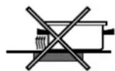
a) The room must be fitted with a ventilation system which vents smoke and gases from combustion to the outside. This must be done by means of a hood or electric ventilator that turns on automatically each time the hood is operated.
In a chimney stack or branched flue. Directly to the Outside (exclusively for cooking appliances)
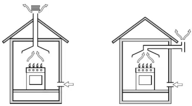
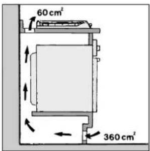
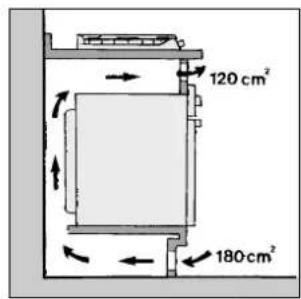
b) The room must also allow for the influx of the air needed for proper combustion. The flow of air for combustion purposes must not be less than 2m^3 /h per kW of installed capacity. The supply of said air can be effected by means of direct influx from the outside through a duct with a inner cross section of at least 100~cm^2 which must not be able to be accidentally blocked. Those appliances which are not fitted with a safety device to prevent the flame from accidentally going out must have a ventilation opening twice the size otherwise required, i.e. a minimum of 200cm^2 (Fig. A). Otherwise, the room can be vented indirectly through adjacent rooms fitted with ventilation ducts to the outside as described above, as long as the adjacent rooms are not shared areas, bedrooms or present the risk of fire (Fig. B).
Detail A Adjacent Room to be
Room Vented
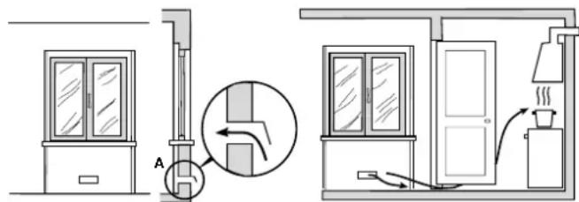
Examples of ventilation holes Enlarging the ventilation slot for comburant air. between window and floor.
Fig.A Fig.B
c) Intensive and prolonged use of the appliance may necessitate supplemental ventilation, e.g. opening a window or increasing the power of the air intake system (if present).
d) Liquidified petroleum gases are heavier than air and, as a result, settle downwards. Rooms in which LPG tanks are installed must be fitted with ventilation openings to the outside in order to allow the gas to escape in the event of a leak. Therefore, LPG tanks, whether empty or partially full, must not be installed or stored in rooms or spaces below ground level (cellars, ect.). It is also a good idea to keep only the tank currently being used in the room, making sure that it is not near sources of heat (ovens, fireplaces, stoves, etc.) that could raise the internal temperature of the tank above 50^ .
Installation of built-in stove tops
The appliance can be installed next to furniture units which are no taller than the top of the cooker hob. The wall in direct contact with the back panel of the cooker must be made of non-flammable material. During operation the back panel of the cooker could reach a temperature of 50^ above room temperature. For proper installation of the cooker, the following precautions must be taken:
a) The hob may be located in a kitchen, a kitonen/diner or bed sitting room, but not in a bathroom or shower room.
b) The furniture standing next to the unit, that is higher than the working boards, must be placed at least 110mm from the edge of the board.
c) The cabinets should be positioned next to the hood at a height of at least 420~mm (Fig. C).
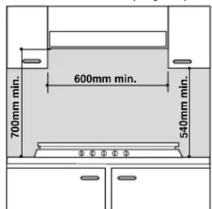
Fig.C
d) Should the hob be installed directly under a cupboard, the letter should be at least 700mm (millimetres) from the worktop, as shown in Fig. C.
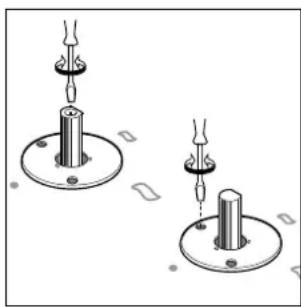
e) The dimensions of the room for the furniture must be those indicated in the figures in the last two pages of the cover. Fixing hooks are provided which allow to place the hob plate on work tops that measure from 20 to 40mm in thickness (see Fig. D). To obtain a good fixing of the hob plate it is advisable to use all the hooks supplied.
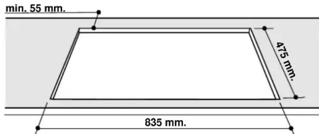
Fig. D
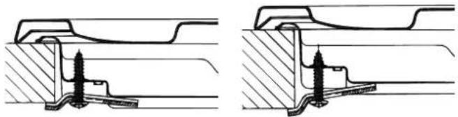
Hook position for Hook position for H=30mm top H=40mm top
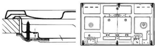
Hook position for Back H=20mm top
N.B: Use the hook contained in the "accessoires set"
f) In the event the cooktop is not installed above a built-in oven, a wood panel must be inserted as insulation. This panel must be placed at least 20mm from the bottom of the cooktop itself.
Important: When installing the hob above a built-in oven, the oven should be placed on two wooden strips; in the case of a joining cabinet surface, remember to leave a space of at least 45 × 560 ~mm at the back.
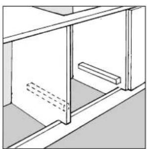
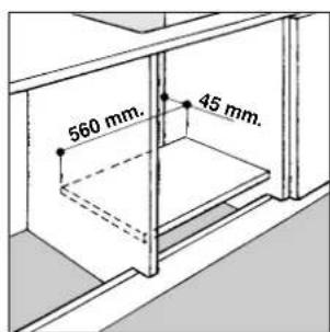
When installing on a built-in oven without forced ventilation, ensure that there are air inlets and outlets for ventilating the interior of the cabinet adequately.
Gas connection for gas hob
The cooker should be connected to the gas-supply by a corgi registered installer. During installation of this product it is essential to fit an approved gas tap to isolate the supply from the appliance for the convenience of any subsequent removal or servicing. Connection of the appliance to the gas mains or liquid gas must be carried out according to the prescribed regulation in force, and only after it is
ascertained that it is adaptable to the type of gas to be used. If not, follow the instructions indicated in the paragraph headed "Adaptation to different gas types". In the case of connection to liquid gas, by tank, use pressure regulators that conform to the regulation in force.
Important: For safety, for the correct regulation of gas use and long life of the appliance, ensure that the gas pressure conforms to the indications given in table 1 "Nozzle and burner characteristics".
Connection to non-flexible tube
(copper or steel)
Connection to the gas source must be done in such a way as to not create any stress points at any part of the appliance.
The appliance is fitted with an adjustable, "L" shaped connector and a gasket for the attachment to the gas supply. Should this connector have to be turned, the gasket must be replaced (supplied with the appliance).
The feeding connector of the gas to the appliance is threaded 1/2 gas male cylinder.
Connection to flexible steel tube
The gas feed connector to the appliance is a threaded, male 1/2'' connector for round gas pipe. Only use pipes and sealing gaskets that that conform to the standards currently in force. The maximum length of the flexible pipes must not exceed 2000mm . Once the connection has been made, ensure that the flexible metal tube does not touch any moving parts and is not crushed.
Check the Seal
Once the appliance has been installed, make sure all the connections are properly sealed, using a soapy water solution. Never use a flame.
Electrical Connection
The cooktops fitted with a tripolar electrical supply cord are designed to be used with alternating current according to the indications on the rating plate located under the cooktop. The earthing wire can be identified by its yellow-green colour.
In the case of installation over a built-in electric oven, the electrical connections for the cooktop and oven should be independent, not only for safety purposes, but also to facilitate removal of one or both in the future.
Electrical Connection for Gas Cooktop
Fit the supply cord with a standard plug for the demand rate indicated on the rating plate or connect it directly to the electrical mains. In the latter case, a single pole switch must be placed between the appliance and the mains, with a minimum opening between the contacts of 3mm in compliance with current safety codes (the earthing wire must not be interrupted by the switch). The power supply cord must be positioned so that it does not reach a temperature in excess of 50^ above room temperature at any point.
Before actual connection make sure that:
-
The fuse and electrical system can withstand the load required by the appliance;
-
That the electrical supply system is equipped with an efficient earth hook-up according to the norms and regulations prescribed by law;
-
That the plug or switch are easily accessible.
Important: the wires in the mains lead are coloured in accordance with the following code:
Green & Yellow - Earth
Blue - Neutral
Brown-Live
As the colours of the wires in the mains lead may not correspond with the coloured markings identifying the terminals in your plug, proceed as follows:
Connect the Green & Yellow wire to terminal marked "E"
or coloured Green or Green & Yellow.
Connect the Brown wire to the terminal marked "L" or coloured Red.
Connect the Blue wire to the terminal marked "N" or coloured Black.
Adapting the Cooktop for Different Types of Gas
To adapt the cooktop to a different type of gas than that for which it was designed, (see the sticker under the hob or on the packaging), the burner nozzles must be changed, as follows:
- Remove the pan supports and slide the burners out of the cooktop.
- Unscrew the nozzles using a 7mm socket wrench and replace them with those for the new type of gas. (See table 1, "Burner and Nozzle Specifications").
- Reassemble the parts following the instructions in reverse order.
- On completing the operation, replace the old rating label with the one showing the new type of gas; the sticker is available from our Service Centres.
If the gas pressure is different than that prescribed, a pressure regulator must be installed at the source, in compliance with national standards governing the use of piped gas regulators.
Regulation of Air Supply to the Burner
The burners do not need any primary air regulator.
Minimum Regulation
Minimum regulation:
- Turn the gas valve to minimum.
- Remove the knob and turn the regulator screw (positioned either on the side of the top or inside the shaft - Figs. A and B) clockwise until the flame becomes small but regular.
N.B.: In the case of liquid gas, the regulation screw must be fully screwed in (clockwise).
- Make sure that, when the knob is turned rapidly high to low, the flame does not go out.
- In the event of a malfunction on appliances with the security device (thermocouple) when the gas supply is set at minimum, increase the minimum supply levels using the regulator screw in Fig. A - B.
Once the adjustment has been made, apply sealing wax, or a suitable substitute, to the old seals on the by-pass.
Burners and Nozzle Specifications
| Table1 (For Hungary) G | 20 G 25.1 G 30 | |||||
| Burner | Thermal power kW | Nozzle 1/100 (mm) | Thermal power kW | Nozzle 1/100 (mm) | Thermal power kW | Nozzle 1/100 (mm) |
| Reduced Fast (RR) | 2,45 | 110 | 1,90 | 110 | 2,30 | 80 |
| Semi Fast (Medium) (S) | 1,60 | 96 | 1,25 | 96 | 1,50 | 64 |
| Auxiliary (Small) (A) | 0,90 | 71 | 0,65 | 71 | 0,90 | 50 |
| Triple Crown (TC) | 3,15 | 133 | 2,45 | 133 | 2,90 | 91 |
| Semi-FishBurner (SP) | 1,50 | 88 | 1,15 | 88 | 1,40 | 60 |
| Supply pressures | 25 mbar | 25 mbar | 30 mbar | |||
At 15^ and 1013 mbar-dry gas
P.C.I.G20 35,9MJ/M
P.C.I. G30 122,8 MJ/M³
P.C.I.G25.1 30,9MJ/M
| Table 1 Liquid gas Natural gas | ||||||||||
| Burner Diameter | (mm) | Thermal power kW (p.c.s.) | By-pass 1/100 (mm) | Nozzle 1/100 | Flow* g/h | Nozzler 1/100 | Flow* l/h | |||
| Nom. | Red. (1) (mm) *** ** | |||||||||
| Fast (Large) (R) | 100 | 3.00 | 0.7 | 41 | 39 | 86 | 218 | 214 | 116 | 286 |
| Reduced Fast (RR) | 100 | 2.60 | 0.7 | 41 | 39 | 80 | 189 | 186 | 110 | 248 |
| Semi Fast (Medium) (S) | 75 | 1.65 | 0.4 | 30 | 28 | 64 | 120 | 118 | 96 | 157 |
| Auxiliary (Small) (A) | 55 | 1.00 | 0.4 | 30 | 28 | 50 | 73 | 71 | 71 | 95 |
| Triple Crown (TC) | 130 | 3.25 | 1.3 | 60 | 57 | 91 | 236 | 232 | 133 | 309 |
| Semi-FishBurner (SP) | - | 1.50 | 0.7 | 41 | 39 | 60 | 109 | 107 | 88 | 143 |
| Supply pressures | Nominal (mbar) | 28-30 | 37 | 20 | ||||||
| Minimum (mbar) | 20 | 25 | 17 | |||||||
| Maximum (mbar) | 35 | 45 | 25 | |||||||
- At 15°C and 1013 mbar-dry gas
** Propane P.C.S. = 50,37 MJ/kg
*** Butane P.C.S. = 49,47 MJ/kg
Naturale P.C.S. = 37,78 MJ/m
(1) Only for appliances with security device (ref. F).
This appliance complies with the following European Economic Community directives:
- 73/23/EEC of 19/02/73 (Low Voltage) and subsequent modifications;
89/336/EEC of 03/05/89 (Electromagnetic Compatibility) and subsequent modifications;
90/396/EEC of 29/06/90 (Gas) and subsequent modifications;
93/68/EEC of 22/07/93 and subsequent modifications. - 2002/96/EEC
The European Directive 2002/96/EC on Waste Electrical and Electronic Equipment (WEEE), requires that old household electrical appliances must not be disposed of in the normal unsorted municipal waste stream. Old appliances must be collected separately in order to optimise the recovery and recycling of the materials they contain and reduce the impact on human health and the environment. The crossed out "wheeled bin" symbol on the product reminds you of your obligation, that when you dispose of the appliance it must be separately collected. Consumers should contact their local authority or retailer for information concerning the correct disposal of their old appliance.
PH 940 M / PH 940 MS
PH 941 M / PH 941 MS

PH 941 MSTV PH 941 MSTV GH
PH 930...
PH 941 MSTB PH 941 MSTB GH
PH 960 MST PH 960 MST GH PH 960 MST R
PH 940 MST
Raccordement gaz (Pour la France)

- Close-up View
- A Gas Burners
- NOTICE
- How To Use Your Appliance
- Gas Burners
- Electric Hot Plates (only on certain models)
- Cooktop Broiler (only on certain models)
- Ceramic Glass Module (only on certain models)
- How to Keep Your Cooktop in Shape
- Greasing the Taps
- Practical Advice
- Practical Advise on Using the Burners
- Practical Advice on Using the Half Fish-Kettle Burner
- Practical Advice on Using the Electric Hot Plates
- Practical Advise on Using the Broiler
- Practical Advise on Using the Ceramic Glass Module
- Is there a problem?
- The burner does not light or the flame is not uniform around the burner.
- The flame does not stay lighted on the model with the safety device.
- The burner does not remain on when set to "Low".
- The cookware is not stable.
- Safety Is a Good Habit to Get Into
- Prevent children and the disabled from coming into contact or having access to the following, as they are possible sources of danger:
- The following should be avoided:
- The assistance of qualified personnel must be called upon in the following cases:
- Contact service centers authorized by the manufacturer in the following cases:
- It is recommended that you follow the guidelines below:
- Positioning for gas hob
- Installation of built-in stove tops
- Hook position for Back H=20mm top
- Gas connection for gas hob
- Connection to non-flexible tube
- Connection to flexible steel tube
- Check the Seal
- Electrical Connection
- Electrical Connection for Gas Cooktop
- Adapting the Cooktop for Different Types of Gas
- Regulation of Air Supply to the Burner
- Minimum Regulation
- Burners and Nozzle Specifications
- This appliance complies with the following European Economic Community directives:
- Raccordement gaz (Pour la France)
Brand : Ariston Thermo
Model : PH 960 MST GH
Category : Cooker