AH 290 - Boiler A.O. Smith - Free user manual and instructions
Find the device manual for free AH 290 A.O. Smith in PDF.
| Product type | Air/water heat pump for domestic hot water production (DHW) |
| Brand | A.O. Smith |
| Model | AH 290 |
| Dimensions (H x D) | 1815 x 660 mm (with fittings, total height) |
| Weight | 105 kg |
| Tank volume | 285 liters |
| Power supply | 230 V / 50 Hz |
| Recommended fuse | 13 A |
| Refrigerant | R134a (0.9 kg) |
| COP (coefficient of performance) | 3.2 (at air 15°C / water 15-45°C) |
| Heating power | 1.96 kW |
| Absorbed electrical power | 0.56 kW |
| Backup electric heating element | 1.5 kW |
| Max water temperature | 65°C (with electric cartridge) |
| Ambient air temperature range | 8°C to 35°C |
| Sound level | 50 dB(A) at 1 m |
| Air flow | 280 m³/h |
| Tank material | Specially enameled steel |
| Max service pressure | 10 bars |
| Maintenance | Periodic cleaning of the evaporator and anode check every 2 years |
| Safety | High pressure switch and safety circuit breaker for the heating element |
| Warranty | 1 year on parts (subject to installation and use conditions) |
Frequently Asked Questions - AH 290 A.O. Smith
User questions about AH 290 A.O. Smith
0 question about this device. Answer the ones you know or ask your own.
Ask a new question about this device
Download the instructions for your Boiler in PDF format for free! Find your manual AH 290 - A.O. Smith and take your electronic device back in hand. On this page are published all the documents necessary for the use of your device. AH 290 by A.O. Smith.
USER MANUAL AH 290 A.O. Smith
Installation, User and Service Manual
Manuel d installation, Mode d employi, Manual d entretien
Read this manual carefully
Warning
Read this manual carefully before starting up the water heater. Failure to read this manual and to follow the instructions in this manual may lead to accidents, personal injury, and damage to the appliance.
Copyright © 2008 A.O. Smith Water Products Company
All rights reserved.
Nothing from this publication may be copied, reproduced and/or published by means of printing, photocopying or by whatsoever means, without the prior written approval of A.O. Smith Water Products Company.
A.O. Smith Water Products Company reserves the right to modify specifications stated in this manual.
Trademarks
Any brand names mentioned in this manual are registered trademarks of their respective owners.
Liability
A.O. Smith Water Products Company accepts no liability for claims from third parties arising from improper use other than that stated in this manual and in accordance with the General Conditions registered at the Eindhoven Chamber of Commerce.
Refer further to the General Conditions. These are available on request, free of charge.
Although considerable care has been taken to ensure a correct and suitably comprehensive description of all relevant components, the manual may nonetheless contain errors and inaccuracies.
Should you detect any errors or inaccuracies in the manual, we would be grateful if you would inform us. This helps us to further improve our documentation.
More information
If you have any comments or queries concerning any aspect related to the appliance, then please do not hesitate to contact:
A.O. Smith Water Products Company
PO Box 70
5500 AB Veldhoven
Netherlands
Telephone: 0870-AOSMITH
0870-2676484
General: +31 40 294 25 00
Fax: +31 40 294 25 39
E-mail: info@aosmith.nl
Website: www.aosmithinternational.com
In the event of problems with connecting to the gas, electricity or water supply, please contact your installation's supplier/installation engineer
Table of contents
A
1.About the product 37
1.1 Scope of delivery 37
1.2 Product description 37
1.3 Technical data 37
1.4.1 Refrigerant circuit - description 38
1.4.2 Refrigerant circuit - schematic 39
1.5.1 Water circuit - description 40
1.5.2 Requirement for the water circuit 40
1.5.3 Dimensions 40
1.5.4 Water circuit -hydraulics diagram 41
1.6 Electrical schematic 42
2.Before installation / Placement into 44 service
2.1 Important safety instructions 44
2.1.1 Cooling system - safety instructions 44
2.1.2 Electrical system - safety instructions 44
2.1.3 Water circuit - safety instructions 44
2.2 Delivery 44
2.3 Storage 44
2.4 Transport 45
2.4.1 Transport with forklift 45
2.4.2 Unloading the heat pump 45
2.4.3 Transport with trolley 45
2.5 Placement/set-up 46
3.Installation 49
3.1 Water connection 49
3.2 Placement of pipe connections 49
3.3 Connection of condensation drain 49
3.4 Air intake and exhaust 50
3.5 Checking 50
4. Placement into service / operation 51
4.1 Placement into service of water circuit 51
4.2 Electricity- connecting 51
4.3Cooling circuit 51
4.4 Hints for energy savings 51
B
1. User Guide 52
1.1 Use 52
1.2 Altering of the operation data 53
1.3 Operating menu 54
1.4Factory default scheme 55
2. Fonction 56
2.1 Description 56
2.2 Exact capacity 56
2.3Operation safety 57
2.4Warnings 57
3.Maintenance 58
3.1 Cooling system and fan 58
3.2 Water circuit and tank
3.3 Demounting/Putting the unit out of 58
service 59
4. Fault finding 60
4.1 High pressure switch 60
4.2 Safety breaker for heating element 60
4.3 Heat pump will not run 60
5.Warranty 61
A
1. About the product
1.1 Scope of delivery
- Heat pump with built-in controls
- Installation manual with technical data
- Operating instructions
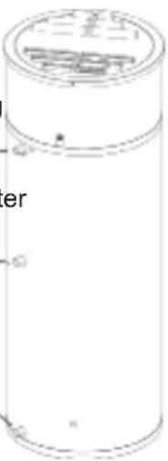
1.2 Product description
The AH 290 is a domestic water heat pump with a condenser on the outside of the tank. The application area and operating principles of the heat pump are specified in the operating instructions.
1.3 Technical data
| Domestic water heat pump | ||
| Diameter without pipe connections mm Ø660 | ||
| Height mm 1770 | ||
| Weight kg 105 | ||
| Electrical connections V/Hz 230/50 | ||
| Fuse on heat pump A 13 | ||
| Refrigerant / amount filled - / kg R134a / 0,9 | ||
| Performance data | ||
| Performance specified for heating of domestic water from 15°C to 45°C | ||
| Thermal output(with air 15°C / water 15°C – 45°C) | kW 1,96 | |
| Power input(with air 15°C / water 15°C – 45°C) | kW 0,56 | |
| COP(with air 15°C / water 15°C – 45°C) | 3,2 | |
| Power consumption electrical cartridge / heating element | kW 1,5 | |
| Operating range / limits | ||
| Min. air temperature | °C | 8 (±0,5°C) |
| Max. air temperature | °C | 35 |
| Max. water temperature | °C | 55 |
| Max. water temperature(with operation of heat pump and electric cartridge) | °C | 65 |
| Sound level | ||
| 1 meter in front of unit | dB(A) | 50 |
| Domestic water container | |||
| Material Steel specially enamelled | |||
| Net volume 1285 | |||
| Airflow volume | |||
| Airflow volume m3/h 280 | |||
1.4.1 Refrigerant circuit - description
The cooling system is used for processing the heat in the inlet air. This is the manner by which the extracted heat is transferred to the water. This process is only possible with the external addition of energy, which takes place in the compressor.
In the vaporizer, heat is absorbed from the air and refrigerant in gaseous form and fed to the compressor. In the compressor, the refrigerant is raised up to a higher pressure and energy level, so it can deliver the heat to the water through the condenser pipe, which is coiled around the tank.
The condensed coolant fluid is throttled down to a lower pressure using the expansion valve so it becomes possible to repeat the cooling cycle in the vaporizer.
1.4.2 Refrigerant circuits
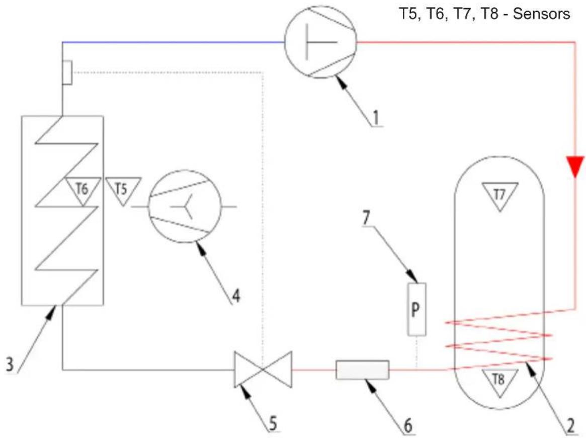
| Component overview | |
| N° : Descriiption | |
| 1 Compressor | |
| 2 Condenser | |
| 3 Vaporiser | |
| 4 Centrifugal fan | |
| 5 Expansion valve | |
| 6 Drying filter | |
| 7 Pressure switch |
1.5.1 Water circuit - description
The water circuit will be constructed with respect to the applicable norms and requirements. Please see the specifications in sections 3.1 and 3.2.
1.5.2 Requirements for the water circuit
Depending upon the materials used in the water circuit of the dwelling, incorrect material combinations can lead to corrosion damage due to galvanic corrosion. This requires special attention with the use of galvanized components and components that contain copper.
1.5.3 Dimensions

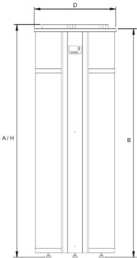
Dimensions (all measurements are in mm, except when indicated other wise)
| Description AH 290 | ||
| A Total height 1815 | ||
| B Height of top of appliance 1790 | ||
| D Appliance diameter 660 | ||
| H Height air in-/outlet 1815 | ||
| J Height air inlet 60 | ||
| M Height of cold water supply 110 | ||
| N Height of hot water outlet 1410 | ||
| P Height of cleaning opening 45 | ||
| V Height of recirculation connection 820 | ||
| W Height condensation drain | 1345 | |
| Z Height of electric element connection | 925 | |
| 1 Cold water supply connection (male) | R 3/4" | |
| 2 Hot water outlet (male) | R 3/4" | |
| 6 Cleaning/inspection opening | Ø 110 | |
| 7 Condensation drainage connection (female) | Ø 12 | |
| 11 Electric element connection (female) | G 1 1/2" | |
| 14 Recirculation connection (female) | R 3/4" | |
1.5.4 Water circuit - hydraulics diagram
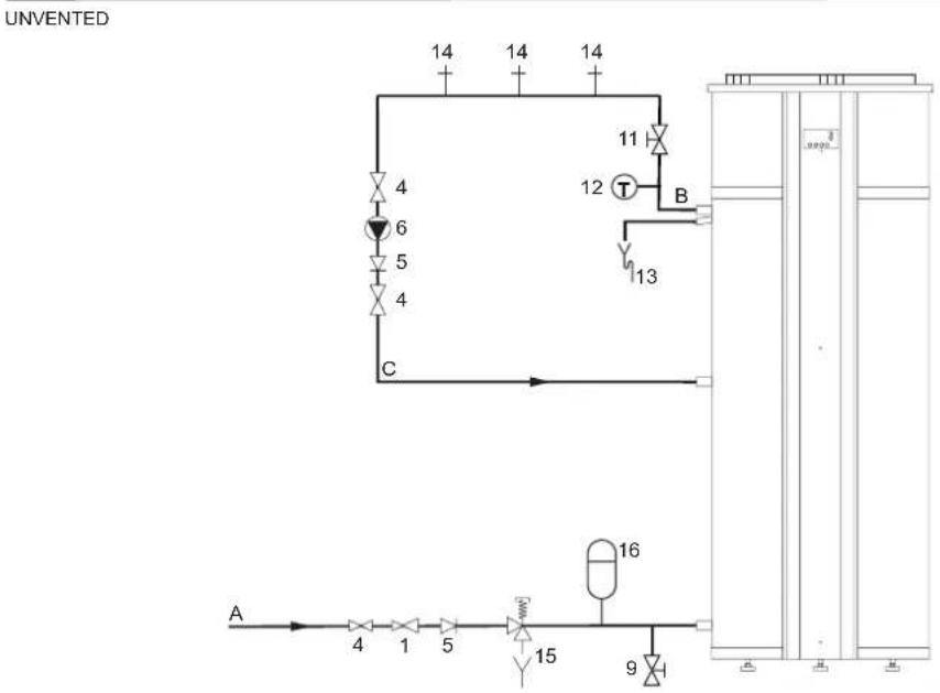

Legends
Only applicable numbers are mentioned.
- pressure-reducing valve (mandatory if the mains water pressure exceeds 8 bar)
- stop valve (recommended in pipe C and mandatory in pipe A)
- non-return valve (mandatory)
- circulation pump (optional)
- drain valve (mandatory)
- service stop valve (recommended)
- temperature gauge (recommended)
-
condensation drainage (mandatory)
-
hot water draw-off points
- expansion valve (mandatory)
- expansion vessel (mandatory)
- 3-way aeration valve (recommended)
- water tank
- float valve
A. cold water supply
B. hot water supply
C. circulation pipe
E. overflow pipe
H. overflow safety

2. Before Installation / Placement into service
2.1 Important safety instructions
In the design and implementation of the heat pump, all relevant EU guidelines have been adhered to.
Work on the heat pump may only be performed by trained personnel! Take all necessary precautions in order to avoid accidents while working!
2.1.1 Cooling system - safety instructions
The trained repairman must see to it that parts containing the refrigerant are emptied to a level at which the execution of the work can occur in a responsible manner without any dangers, before the commencement of repairs and service work.
When repairing and servicing the heat pump with the refrigerant system opened, and particularly for work with an open flame (soldering, welding, etc.), precautions must be taken to prevent fires from starting.
2.1.2 Electrical circuit - safety instructions
When working on the heat pump, the main supply must always be disconnected - pull the plug out!
When connecting the heat pump to the power supply, the local and national rules and norms must be adhered to. In addition, regard must be paid to possible requirements posed by the energy supplier.
2.1.3 Water circuit - safety instructions
Only drinking water quality water may be used. During installation, regard must be paid to the choice of materials and it must be ensured that they can work together without problems in the entire circuit.
Special attention must be paid when using galvanized components and components containing aluminum!
Safety equipment must be installed to prevent over pressure in the system.
All pipe work must comply with water safety regulations.
2.2 Delivery
The heat pump is delivered without water, condense water tube and the safety equipment for the water circuit.
2.3 Storage
The heat pump must be stored upright without water and in its packaging.
2.4 Transport
When carefully transporting the heat pump over short distances, it can be tilted up to 45^ . If this limit is exceeded, the heat pump must stand in its normal upright position for at least 1 hour before it may be started.
Transport and storage may take place at temperatures between -10 and +50^ .
The heat pumps top / casing is not suitable for lifting with and must be carefully avoided during transport.
2.4.1 Transport with forklift
For transport with a forklift, the heat pump must stand on the associated transport frame. Always lift it slowly. Due to the high position of the centre of gravity, the heat pump must be secured against tipping during transportation.
2.4.2 Unloading the heat pump
In order to avoid damages, the heat pump must be unloaded on a flat surface.
2.4.3 Transport with trolley
The heat pump may only be transported on an associated transport frame.
The heat pump must be secured against sliding on the trolley.
Water connections, etc., may not be used for transportation purposes.
Make sure that the trolley does not damage the cabinet and the connections.
2.5 Placement/set-up
The heat pump may only be installed in a frost-free room.
The installation location should comply with the following criteria:
- Room temperature between +8 and +35°C.
- Drain possibility for condensate water.
- No abnormal dust concentration in the air.
Solid base (approx. 500kg / m^2 - To achieve problem-free functioning and to allow access for service, it is recommended that 0.5m free space be maintained around the unit.
Set-up sequence:
- Remove the packaging from the pallet.
- Remove the transport fittings from the pallet.
- Take the heat pump off the pallet and place it at the desired location.
Adjust the heat pump vertically by adjusting the feet.
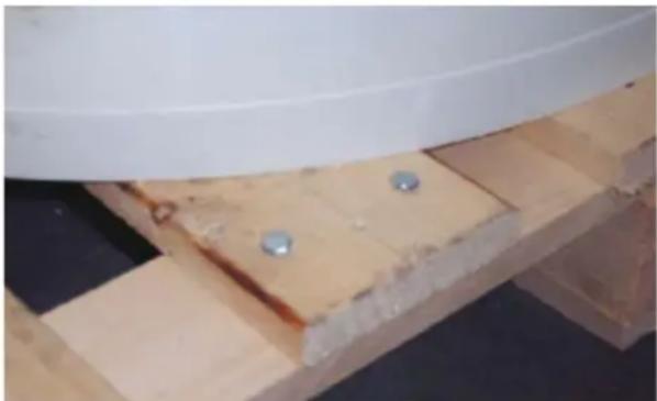
1. Screws to be removed (hexagonal head).

2. Screws to be removed.
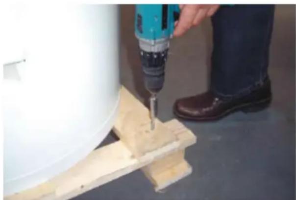
3. Removal of screws.

- Removal of product :
a: Glide product carefully to one side a bit.
b: Bow over to the same side together with 2 pcs. of wood beneath.
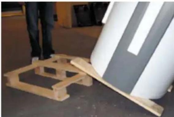
- Carry on with removal :
c: Remove the lower part of the palette while keeping the product in an angle position, still with 2 pcs. wood beneath
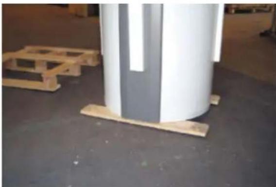
- Product on floor with 2 pcs. of wood.
- Removal of 1st piece of wood (can be released if product bowed a bit to one side).

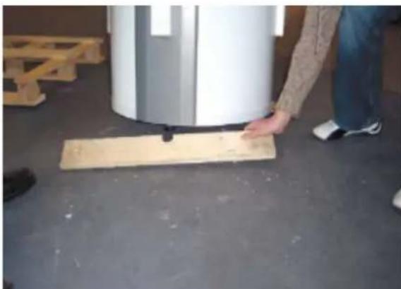
- Removal of 2nd piece of wood (bow the product a bit to another side to release it).
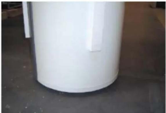
- Palette removed.
3. Installation
3.1 Water connection
During installation, regard must be paid to the dimensions of the pipes with respect to the pre-existing water pressure and the pressure loss in order to ensure sufficient pressure and water flow rates at the draw-off point.
The maximum working pressure is 10 bars, and the maximum operating temperature is 65^ . If necessary, the supply pipe must be equipped with a pressure reduction valve and possibly a filter.
As for all pressure vessels, the heat pumps connections must also be equipped with an approved safety valve on the service side and an approved check valve on the supply side.
All pipe work must comply with water safety regulations
3.2 Placement of pipe connections
Hot water outlet is mounted on the upper connecting branch. (3 / 4^ RG
If the unit is used with the circulation of the hot water supply, the middle connecting branch is used as a return path. (3 / 4^ RG
Inlet of fresh cold water is mounted on the bottom connecting branch. (3 / 4^ RG
It is recommended to use 34 flex tube for the connection of the water connection, to avoid possible sound from the vibration.
No holes for fittings or the like may be drilled in the product! Such would be able to damage the functionality of the product and cause the product to have to be scrapped!
3.3 Connection of condensation drain
While the heat pump is running, some condensation water will occur, which is conducted to the drain connecting branch (1).
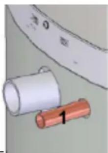
The quantity of condensation water depends upon the humidity of the air going through the inlet to the heat pump.
The condensation connecting branch must be equipped with a hose with a tight air trap, and run to a drain. The air trap must contain a water column of at least 60~mm
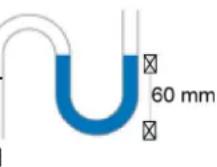
It is also possible to use other tight air traps, like a tube with one turn.
If mounting of the air trap is omitted, water damage or damage to the heat pump can arise! If the air trap is not correctly mounted, the warranty will not apply!
3.4 Air intake and exhaust
Make sure that there is sufficient free space around the heat pump. Place the inlet on the back side of the product, and the outlet on the front side of the product.
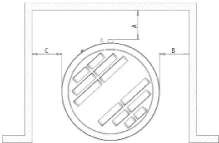
The following applies:
- Min. distance from the floor to the ceiling: 2,1 m
- Placing as shown on the picture (placing in a recess):
C min = B min = 500 mm; A min = 200 mm
- If C > 1 m (placing in a corner): A min = B min = 200 mm
- If C > 1 m and B > 1 m (placing at the wall): A min = 200 mm
The inlet air may not be polluted with aggressive components (ammonia, sulphur, chlorine, etc.). Parts in the system may be damaged.

The inlet and exhaust ducts, on the top of the heat pump, must not be covered! There may not be any abnormal admission in the air.
3.5 Checking
After the installation, it is recommended that the checks be performed to ensure that the connections are sealed and that the drainage of the condensation water is unobstructed.
4. Placement into service / operation
4.1 Placement into service of the water circuit
Fill the container via the connecting branch, and aerate the tank by letting one of the hot water taps located at the highest elevation within the dwelling stand open until air no longer comes out with the water.
The container can normally hold 285 litres of water.
Check the entire circuit to be sure it is sealed.
4.2 Electricity - connecting
Connect the heat pump to the public electrical grid.
4.3 Cooling circuit
The cooling circuit is delivered ready to run and no work need be performed on it. The electronic controls automatically take over all functions concerning the operation of the compressor as well as the ventilator.
If needed, set the controls to the desired water temperature. The factory setting is 50^ (see the operating instructions for more detailed directions).
4.4 Hints for energy savings
Do not set the water temperature higher than necessary.
The best utilisation of the heat pump occurs at low water temperatures.
The use of circulation will increase the energy consumption of the heat pump significantly.
The AH 290 comes with a factory setup, which enables an immediate start of the unit. The factory setup is basic and must be adjusted to the operational requirements and demands of the individual home, in order to obtain the optimum operating benefit from the unit.
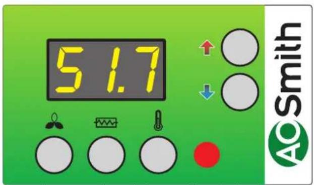
1.1 Use

User menu
The value of a menu item is shown when pressing the key/key combination below. The value may be changed with the arrows when the key/key combination is held down simultaneously. The control will return to standard indication if no buttons have been pressed for app. 15 seconds.

P1: Heat Pump ON/OFF
On this button it is possible to change the function between: standby and automatic operation after setpoint P3. (step 0, step 1) Step 0: The heat pump is now off and only the control is active. Step 1: The heat pump is in operation mode and drives after setpoint thermostat P3.

P2: Operation for the electrical cartridge
The heat pump comes with an extra electrical cartridge for heating of the sanitary hot water. On this button it is possible to turn on the electrical cartridge if required. By adjusting the setpoint to 1 the electrical cartridge will turn on after setpoint P5 (operating thermostat for the electrical cartridge). The electrical cartridge is not on if this setpoint it set to 0. Note! When the ambient temperature is under 8^ or over 35^ the electrical cartridge will turn on even if P2 = 0

P3: Operating thermostat for heat pump
The required sanitary water temperature may be set between 0 - 55^ which is heated up by the heat pump. Factory setting: 52^ Max. water temperature: 55^

P5: Operating thermostat for electrical cartridge
The sanitary water temperature may be adjusted between 0 - 65^ .
The electric cartridge solely heats the top half of the container, while the heat pump still heats the lower half of the container.
Factory setting: 50^

Display indication It is possible to view various temperatures in the display, by pressing the arrows until the required temperature has been shown.

After app. 5 seconds, the temperature is shown. The temperature is shown for app. 30 seconds until the display returns to standard. Following temperatures may be shown:

T5: Ambient temperature
T6: Cooling coil
T7: Sanitary water top
T8: Sanitary water bottom
1.2 Altering of the operation data
Usually, the display shows the water temperature.
Press (arrow up) and (arrow down) simultaneously for app. 10 seconds in order to enter the operating menu. To show the chosen value press The display will now show the first point E0 in the operating menu. The operating menu will close and return to the main menu if a button has not been pressed for 15 sec.
If you wish to scroll through the operating menu, it may be done by pressing (arrow up) or (arrow down). The value of a point is shown when pressing (temp button). The value may be changed with the (arrow up) or (arrow down) while simultaneously pressing (temp button). The control will return to standard indication if no buttons have been pressed for app. 15 seconds.
1.3 Operating menu
E0: Factory default
If the system does not function as expected, even though the set points have been adjusted, and the cause is impossible to locate, it is recommended to note down the settings in the schedule. Thereafter the set point must be adjusted to 1 and wait until the control returns to standard settings. Now all the set points have been changed to the factory default. It is now possible to start all over and adjust the set points.
Factory setting: 0
E8: Disinfection function ON/OFF
By setting the point to 1, the electric cartridge will provide 65^ hot water, once a week, in order to disinfect the tank (legionella protection function). Factory setting: 0
E16: Min. airflow
This value shows the minimum speed at which the fan is permitted to run when operating. Notice that the cooling system may be overloaded, resulting a drop out of the high-pressure switch, if the value has been set too high. The value should not be chosen higher than necessary, in order to secure a minimal airflow through the cooling coil. Adjust this value between 0 - 100% .
Factory setting: 0
E21: TX set
In order to avoid high operating pressures in the cooling system, the system output must be reduced for the remaining part of the heating period. This parameter indicates the water temperature at which the reduction should start. It may be set to 0 - 55^ .
Factory setting: 50
E23: Tmop
This value indicates the maximum permitted evaporation temperature. This prevents overloading of the compressor system at high ambient temperatures.
Adjust this value between 0 - 25^
Factory setting: 25
E45: dTair-set
Here it is possible to choose minimum cooling of the air, while heating the water. The control will adjust the speed of the fan to make sure the air will be cooled at the exact temperature chosen. In case the control needs to cool the air due to technical reasons, the value will be controlled by the automatic function. When requiring a higher fan speed, the value may be reduced. Remember though, the fan will run faster, using more energy, if the values are set to low.
Factory setting: 1
1.4 Factory default scheme
| Factory default scheme Date Date | |||
| E0: Factory default 0 0 | |||
| E8: Disinfection function ON/OFF 0 | |||
| E16: Min. air flow 0 | |||
| E21: TX-set 50 | |||
| E23: Tmop 25 | |||
| E45: dTair set 1 | |||
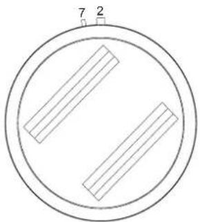
2. Function
2.1 Description
The flow diagram shows the location of the sensors, while the circuit board shows the relay outputs and the other outputs for connecting fan and control panel.
Use of hot tap water heat pump:
The AH 290 is an independent sanitary hot water heat pump to be installed in rooms that are not part of the living space, e.g. basement rooms. The only requirement to the room is that the air temperature stays between 8^ and 35^ .
We recommend basement rooms because even during the winter heat is supplied from the surrounding soil layer.
Heat pump operation:
The control starts the compressor shortly after hot water has been tapped. The compressor will run until the entire tank has been heated to the set temperature again. Usually the heat pump can produce a sufficient amount of hot tap water covering the needs of a common family.
Water heating:
When hot water is drawn off, the tank will be refilled with cold water at the bottom. A sensor measures the temperature at the bottom of the tank and starts the compressor if the temperature has fallen 5^ below the set temperature. The compressor stops, when the water has been heated to the set temperature. While the compressor operates, the fan runs and circulates air through the cooling coil.
Fan operation:
The fan may be set to run continuously, when the compressor has stopped - by selecting level 2 or level 3. This option may be chosen when the heat pump is used as an extraction system in the residential wet rooms. If the input to T4 short circuits, the control is forced to run at 3rd speed. This may be used in order to achieve more extract in e.g. bathroom, while taking a shower. When breaking the short circuit on the input pins to T4, the control will return to its previous step.
2.2 Extra capacity
If a situation should occur where the heat pump is not capable of producing enough hot tap water (more people in the house), an extra electrical cartridge in the container can be switched on. Doing so, it is possible to heat up more water. It is possible to set the desired temperature to which the electrical cartridge should heat up the water. (Only use the electrical cartridge when needed, as it uses more energy than the compressor). The electrical cartridge can be activated manually on the display.
2.3 Operation safety
High-pressure switch:
To prevent the compressor from exceeding its range of operation, there is an integral high-pressure switch, which interrupts when the pressure is 20 bar in the cooling unit. Activate the red reset button once the cause of the error has been identified. When the high-pressure switch interrupts, the red LED will flash until the reset button manually or the pressure has fallen to 15 bar or the cause of error has been identified. When the high-pressure switch interrupts, the red light will flash until the reset button on the pressure switch is activated. In order to prevent a repetition of a pressure switch error, the water may be set 2 - 3^ lower.
Safety breaker for electrical heating element
If an error occurs at the heater, the safety breaker trips and stops the heater in order to prevent the tank from being overheated.
When working on the heat pump, always make sure the power supply is disconnected. Any work on this unit may only be carried out by trained personnel!
2.4 Warnings
High-pressure switch:
When the pressure switch trips, the red light on the display will light until the pressure switch is reset.
3. Maintenance
The following instructions must be followed in order to ensure optimum operation of the heat pump.

ower supply to the system must always be switched off opening the heat pumps cover.
When the unit has been installed for the first time make sure the water connections are checked after a few days to make sure there are no leaks. Also check that the condensate drain pipe is not blocked.
Environmental considerations
When the unit is being serviced or its operation is cancelled, please make sure to follow the guidelines for recovery and disposal of all materials according to local procedures and laws.
3.1 Cooling system and fan
Fan:
Maintaining the fans is mainly periodically cleaning of the evaporator. Disconnect the flexible hoses from the top of the unit and unscrew the top plate. Clean the fan with a suitable brush. Do not remove the balancing blocks from the impeller, as this will cause imbalance and with it more noise and fan wear.

risk of injury from sharp-edged fins! Do not damage this fins!
Condensate drain:
When changing the filters in the autumn season, check the condensate drain and tray for blockage by dirt. Fill water in the condensate tray and check that the water runs out unhindered. Should this not be the case the drain must be cleaned. At the same time make sure that the plates of the evaporators are clean.
3.2 Water circuit and tank
Safety valve:
The installer has fitted a safety valve on the cold water supply pipe for the hot water tank. This valve is a protection of the tank against excess pressure when the domestic water expands during heating. The non-return valve, which is fitted before the safety valve on the cold water pipe, prevents the water from flowing back into the cold water pipe. This means that the pressure in the tank will increase to the maximum pressure permitted by the safety valve, at which point it will open and allow the surplus water to escape. If the safety valve did not open, the tank would burst. To make sure that the safety valve is working properly, it should be inspected several times a year. To do this, press the spring-loaded arm on the safety valve and see if water comes out of the valve. Damage caused by a blocked safety valve is not covered by the warranty.
Anode:
In order to prevent corrosion of the enamelled hot water tank, the tank is fitted with a magnesium anode with a 3/4 screw plug. This anode has a life expectancy of 2-5 years. It is nevertheless important to check that the anode is intact at all times. This should be done by inspecting the anode every 2 years and replacing it if it is corroded and measures only 6 - 10mm in diameter. To inspect the anode, turn off the power supply to the system and remove the front cover. The hot water tank has to be drained before the anode can be unscrewed. To do this, turn off the cold water supply, attach a hose to the drain valve to ensure the water runs to the nearest drain. When draining the water from the tank, turn on a hot water tap to prevent negative pressure in the tank. When the tank is empty, the anode can be unscrewed and inspected. When the anode has been fitted again, close the drain cock and turn the valve water supply back on to fill the tank with water. When the tank is full and the cover back on, the power supply can be switched on again.
3.3 Demounting / Putting the unit out of service
The following actions must be taken:
Disconnect the power supply from the unit and disconnect other connections. Shut off the fresh water supply valve and connect a drain hose to the drain valve in order to drain the water.
4. Fault finding
The heat pump is equipped with the following safety devices:
4.1 High-pressure switch
The high-pressure switch protects the heat pump against too high pressure in the cooling circuit.
In case of interruptions (too high pressure), the red light in the control panel will flash and the high-pressure switch will stop the heat pump. The red light lights. Restart the equipment by manually resetting the high-pressure switch.
For reaching the manually resetting, look between the lamella on the top. If the aggregate stops more times repeatedly you should call the service.
4.2 Safety breaker for heating element
The safety breaker protects the equipment against overheating during heating with the electrical cartridge. The safety breaker is mounted on the heater. If the adjusted value (90^) is exceeded the electrical cartridge will disconnect. It can be reconnected when the temperature is below 90^ . To do this, the power to the equipment must be off, front door dismantled. The reset button can now be pressed.
4.3 Heat pump will not run
Please test if:
the power is connected;
- the power is turned on at the wall plug;
- the heat pump is disconnected through the temperature control;
- the temperature of the sanitary water is less than 55^ ;
- the high-pressure switch is disconnected;
- the cooling coil is dirty.
If this does not help locating the error, please contact your local installer or service contractor.
5. Garantie (certificat)
To register your warranty, you should complete and return the enclosed warranty card after which a warranty certificate will be sent to you. This certificate gives the owner of a appliance supplied by A.O. Smith Water Products Company B.V. of Veldhoven, The Netherlands (hereinafter "A.O. Smith") the right to the warranty set out below, defining the commitments of A.O. Smith to the owner.
General warranty
If within one year of the original installation date of a water heater supplied by A.O. Smith, following verification, and at the sole discretion of A.O. Smith, a section or part (with exclusion of the tank) proves to be defective or fails to function correctly due to manufacturing and/or material defects, then A.O. Smith shall repair or replace this section or part.
Tank warranty
If within 3 years of the original installation date of a water heater supplied by A.O. Smith, following inspection, and at the sole discretion of A.O. Smith, the glass-lined steel tank proves to be leaking due to rust or corrosion occurring on the water side, then A.O. Smith shall offer to replace the defective water heater with an entirely new water heater of equivalent size and quality. The warranty period given on the replacement water heater shall be equal to the remaining warranty period of the original water heater that was supplied. Notwithstanding that stated earlier in this article, in the event that unfiltered or softened water is used, or allowed to stand in the water heater, the warranty shall be reduced to one year from the original installation date.
Conditions for Installation and use
The warranty set out in article 1 and 2 will apply solely under the following conditions:
a. The water heater is installed under strict adherence to A.O. Smith installation instructions for the specific model, and the relevant government and local authority installation and building codes, rules and regulations in force at the time of installation.
b. The water heater remains installed at the original site of installation.
c. The appliance is exclusively used with drinking water, which at all times can freely circulate (a separately installed heat exchanger is mandatory for heating salt water or corrosive water).
d. The tank is safeguarded against harmful scaling and lime buildup by means of periodic maintenance.
e. The water temperatures in the heater do not exceed the maximum setting of the thermostats, which form a part of the water heater.
f. The water pressure and/or heat load do not exceed the maximum values stated on the water heater rating plate.
g. The water heater is installed in a non-corrosive atmosphere or environment.
| h. The water heater is connected to a protected cold supply arrangement, which is: approved by the relevant authority; with sufficient capacity for this purpose; supplying a pressure no greater than the working pressure stated on the water heater; and where applicable by a likewise approved temperature and pressure relief valve, fitted in accordance with installation instructions of A.O. Smith applying to the specific model of water heater, and further in compliance with the government and local authority installation and building codes, rules and regulations.i. The appliance is at all times fitted with cathodic protection. If sacrificial anodes are used for this, these must be replaced and renewed when, and as soon as, they are 60% or more consumed. When electric anodes are used, it is important to ensure that they continue to work properly. | |
| Exclusions | The warranty set out in articles 1 and 2 will not apply in the event of:a. damage to the water heater caused by an external factor;b. misuse, neglect (including frost damage), modification, incorrect and/or unauthorised use of the water heater and any attempt to repair leaks;c. contaminants or other substances having been allowed to enter the tank;d. the conductivity of the water being less than 125 μS/cm and/or the hardness (alkaline-earth ions) of the water being less than 1.00 mmol/litre;e. unfiltered, recirculated water flowing through or being stored in the water heater;f. any attempts at repair to a defective water heater other than by an approved service engineer. |
| Scope of the warranty | The obligations of A.O. Smith pursuant to the specified warranty do not extend beyond free delivery from the Veldhoven warehouse of the replacement sections, parts or water heater respectively. Shipping, labour, installation and any other costs associated with the replacement will not be accepted by A.O. Smith. |
| Claims | A claim on grounds of the specified warranty must be submitted to the dealer from whom the water heater was purchased, or to another authorised dealer for A.O. Smith Water Products Company products. Inspection of the water heater as referred to in articles 1 and 2 shall take place in one of the laboratories of A.O. Smith Water Products Company. |
| Obligations of A.O. Smith | A.O. Smith grants no other warranty or guarantee over its water heaters nor the (sections or parts of) water heaters supplied for replacement, other than the warranty expressly set out in this Certificate.Under the terms of the supplied warranty, A.O. Smith is not liable for damage to persons or property caused by (sections or parts, or the glass-lined steel tank of) a (replacement) water heater that it has supplied. |
A.O. Smith Water Products Company
Case postale 70
5500 AB Veldhoven
Pays-Bas
Telephone (gratuit) 008008 - AOSMITH
008008 - 267 64 84
Général: +31 40 294 25 00
Fax: +31 40 294 25 39
E-mail: info@aosmith.nl
Site web: www.aosmithinternational.com
2.5 Placement / disposition
Obligations de A.O. Smith
Copyright © 2008 A.O. Smith Water Products Company
A.O. Smith Water Products Company
Postfach 70
5500 AB Veldhoven
Niederlande
Telefon: 008008 - AOSMITH
008008-2676484
Allgemein: +31 40 294 25 00
Fax: +31 40 294 25 39
E-Mail: info@aosmith.nl
Website: www.aosmithinternational.com