AHD 290 - Boiler A.O. Smith - Free user manual and instructions
Find the device manual for free AHD 290 A.O. Smith in PDF.
User questions about AHD 290 A.O. Smith
0 question about this device. Answer the ones you know or ask your own.
Ask a new question about this device
Download the instructions for your Boiler in PDF format for free! Find your manual AHD 290 - A.O. Smith and take your electronic device back in hand. On this page are published all the documents necessary for the use of your device. AHD 290 by A.O. Smith.
USER MANUAL AHD 290 A.O. Smith
Installation, User and Service Manual
Manuel d installation, Mode d emploi, Manual d entretien
natural_image
Abstract geometric composition with intersecting lines and a blank rectangle (no text or symbols)Copyright © 2008 A.O. Smith Water Products Company
A.O. Smith Water Products Company
Postbus 70
5500 AB Veldhoven
Nederland
Telefoon: 0800 - AOSMITH
0800 - 267 64 84
natural_image
Close-up of a wooden floor with small metal fixtures and a white ceiling fixture (no visible text or symbols)natural_image
Close-up of wooden beams with visible rebar and a small blue object on the surface (no text or symbols)natural_image
Person using a power drill to cut wooden blocks with a tool, no visible text or symbolsnatural_image
Large cylindrical object placed on a wooden pallet in an indoor space (no visible text or symbols)natural_image
Wooden pallet with a large cylindrical object on top, person standing nearby (no visible text or symbols)natural_image
Interior view of a minimalist room with wooden pallets and a large cylindrical structure on a wooden platform (no text or symbols visible)natural_image
Person standing beside a large cylindrical device on a wooden floor, with wooden crates in the background (no visible text or symbols)natural_image
Person sitting on a floor next to a large white cylindrical container, with a wooden board visible (no text or symbols)natural_image
Close-up of a white cylindrical container with a flat lid, placed on a dark floor (no text or symbols visible)natural_image
Illustration of two cylindrical objects, one white and one copper-colored, with no visible text or symbols.Read this manual carefully
Warning
Read this manual carefully before starting up the water heater. Failure to read this manual and to follow the instructions in this manual may lead to accidents, personal injury, and damage to the appliance.
Copyright © 2008 A.O. Smith Water Products Company
All rights reserved.
Nothing from this publication may be copied, reproduced and/or published by means of printing, photocopying or by whatsoever means, without the prior written approval of A.O. Smith Water Products Company.
A.O. Smith Water Products Company reserves the right to modify specifications stated in this manual.
Trademarks
Any brand names mentioned in this manual are registered trademarks of their respective owners.
Liability
A.O. Smith Water Products Company accepts no liability for claims from third parties arising from improper use other than that stated in this manual and in accordance with the General Conditions registered at the Eindhoven Chamber of Commerce.
Refer further to the General Conditions. These are available on request, free of charge.
Although considerable care has been taken to ensure a correct and suitably comprehensive description of all relevant components, the manual may nonetheless contain errors and inaccuracies.
Should you detect any errors or inaccuracies in the manual, we would be grateful if you would inform us. This helps us to further improve our documentation.
More information
If you have any comments or queries concerning any aspect related to the appliance, then please do not hesitate to contact:
A.O. Smith Water Products Company
PO Box 70
5500 AB Veldhoven
Netherlands
Telephone: 0870 - AOSMITH
0870 - 267 64 84
General: +31 40 294 25 00
Fax: +31 40 294 25 39
E-mail : info@aosmith.nl
Website: www.aosmithinternational.com
In the event of problems with connecting to the gas, electricity or water supply, please contact your installation's supplier/installation engineer
Table of contents
A
1. About the product 39
1.1 Scope of delivery 39
1.2 Product description 39
1.3 Technical data 39
1.4 Refrigirant circuit - description 40
1.4.1 Cooling system - description 40
1.4.2 Electrical circuit - description 40
1.4.3 Water circuit - description 40
1.4.4 Refregerant circuit - schematic 41
1.5 Water circuit – description 42
1.5.1 Requirement for the water circuit 42
1.5.2 Dimensions 42
1.5.3 Water circuit – hydraulics diagram 43
1.6 Electrical schematic 44
2. Before installation / Placement into service 45
2.1 Important safety instructions 45
2.1.1 Cooling system – safety instructions 45
2.1.2 Electrical system – safety instructions 45
2.1.3 Water circuit – safety instructions 45
2.2 Delivery 45
2.3 Storage 46
2.4 Transport 46
2.4.1 Transport with forklift 46
2.4.2 Unloading the heat pump 46
2.4.3 Transport with trolley 46
2.5 Placement / set-up 46
2.6 Connection of water pipes 47
3. Installation 50
3.1 Water connection 50
3.2 Placement of pipe connections 50
3.3 Connection of condensation drain 50
3.4 Air intake and exhaust 51
3.5 Checking 51
4. Placement into service / operation 52
4.1 Demands to the hot water circuit 52
4.2 Starting to use the water circuit 52
4.3 Placement in to service of the water circuit 52
4.4 Electricity - connecting 52
4.5 Cooling circuit 52
4.6 Hints for energy savings 53
4.7 Hints for fan operation 53
4.8 Checking 53
B
1. User Guide 54
1.1 Use 54
1.2 Altering of the operation data 55
1.3 Operating menu 56
1.4 Factory default scheme 58
1.5 Defrost program 58
2. Function 59
2.1 Description 59
2.2 Exact capacity 59
2.3 Operation safety 60
2.4Warnings 60
3. Maintenance 61
3.1 Cooling system and fan 61
3.2 Water circuit and tank 61
3.3 Demounting/Putting the unit out of service 63
4. Fault finding 63
4.1 High pressure switch 63
4.2 Safety breaker for heating element 63
4.3 Heat pump will not run 63
5. Warranty 64
A
1. About the product
When construction and building the heat pump all relevant EU guidelines have been followed. (Also see EU-declaration of conformity.)

work carried out on this unit may only be done by skilled panel. Take all necessary precautions to avoid accidents.
1.1 Scope of delivery
- Heat pump with built-in controls
• Installation manual with technical data - Operating instructions
1.2 Product description
The AHD 290 is a domestic water heat pump with a condenser on the outside of the tank. The application area and operating principles of the heat pump are specified in the operating instructions.
1.3 Technical data
| Performance data | ||
| Performance specified for heating of domestic water from 15°C to 45°C | ||
| Thermal output(with air 15°C / water 15°C – 45°C) | kW 1,52 | |
| Power input(with air 15°C / water 15°C – 45°C) | kW 0,43 | |
| COP(with air 15°C / water 15°C – 45°C) | 3,54 | |
| Power consumption electrical cartridge / heating element | kW 1,5 | |
| Operating range / limits | ||
| Max. air temperature | °C 35 | |
| Max. water temperature | °C 55 | |
| Max. water temperature(with operation of heat pump and electric cartridge) | °C 65 | |
| Sound level | ||
| 1 meter in front of unit | dB(A) 52 | |
| Domestic water container | ||
| Material Steel specially enamelled | ||
| Net volume | 285 | ||
| Airflow volume | ||
| Airflow volume m^3/h 250 | ||
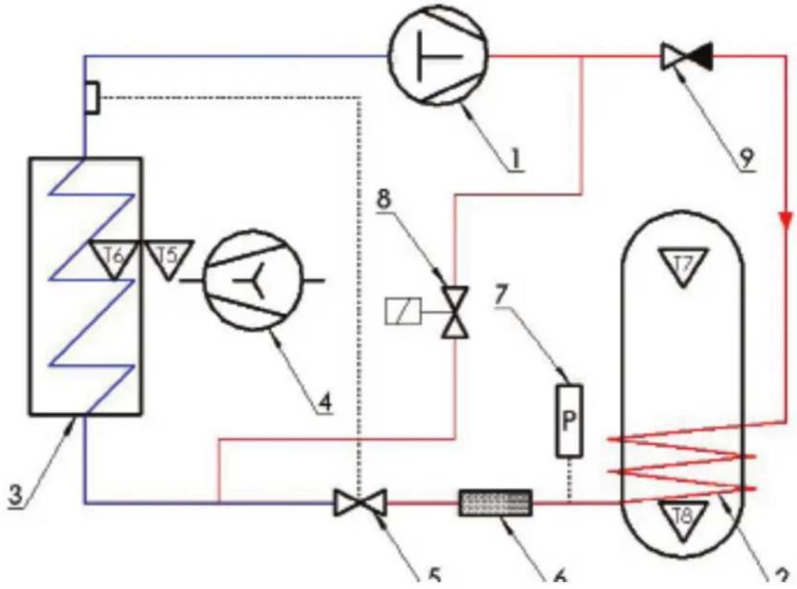
1.4 Refrigerant circuit – description
The cooling system is used for processing the heat in the inlet air. This is the manner by which the extracted heat is transferred to the water. This process is only possible with the external addition of energy, which takes place in the compressor.
In the vaporizer, heat is absorbed from the air and refrigerant in gaseous form and fed to the compressor. In the compressor, the refrigerant is raised up to a higher pressure and energy level, so it can deliver the heat to the water through the condenser pipe, which is coiled around the tank.
The condensed coolant fluid is throttled down to a lower pressure using the expansion valve so it becomes possible to repeat the cooling cycle in the vaporizer.
1.4.1 Cooling system - description
The skilled technician must make sure that all refrigerant carrying parts are emptied to a level where work may be carried out without any risk to people or materials, before repairs and services are carried out.
When repairing and servicing the heat pump in which the refrigerant system has to be opened, always take extra care. If the use of an open flame is needed, (Welding, soldering etc.) special care must be taken in order to prevent fire.
1.4.2 Electrical circuit - description
When work is carried out on the heat pump, the main supply must be disconnected. (Pull the plug.)
When the unit is connected to the supply all local and national regulations must be followed, along with the demands from the power supplier.
1.4.3 Water circuit - description
Only water in drinking quality may be used. During installation the choice of material must be taken into account, and made sure those are compatible in the entire circuit. Safety equipment must be installed to prevent over pressure in the system.
All pipe work must comply with water safety regulations.
1.4.4 Refriferant circuits
T5, T6, T7, T8 - Sensors
flowchart
graph TD
    A[" Tank 3 "] --> B[" Valve 4 "]
    B --> C[" Valve 5 "]
    C --> D[" Valve 6 "]
    D --> E[" Control Unit 1 "]
    E --> F[" Valve 7 "]
    F --> G[" Control Unit 2 "]
    G --> H[" Valve 8 "]
    H --> I[" Control Unit 9 "]
    I --> J[" Valve 9 "]
    J --> K[" Control Unit 10 "]
    K --> L[" Valve 11 "]
    L --> M[" Control Unit 11"]
    M --> N[" Valve 12 "]
    N --> O[" Control Unit 12"]
    O --> P[" Valve 13 "]
    P --> Q[" Control Unit 13"]
    Q --> R[" Valve 14 "]
    R --> S[" Control Unit 14"]
    S --> T[" Valve 15 "]
    T --> U[" Control Unit 15"]
    U --> V[" Valve 16 "]
    V --> W[" Control Unit 16"]
    W --> X[" Valve 17 "]
    X --> Y[" Control Unit 17"]
| Component overview | |
| N° : Description | |
| 1 Compressor | |
| 2 Condenser | |
| 3 Vaporiser | |
| 4 Centrifugal fan | |
| 5 Expansion valve | |
| 6 Drying filter | |
| 7 Pressure switch | |
| 8 Magnetic valve | |
| 9 One-way valve |
1.5 Water circuit – description
The water circuit will be constructed with respect to the applicable norms and requirements. Please see the specifications in sections 3.1 and 3.2.
1.5.1 Requirements for the water circuit
Depending upon the materials used in the water circuit of the dwelling, incorrect material combinations can lead to corrosion damage due to galvanic corrosion. This requires special attention with the use of galvanized components and components that contain copper.
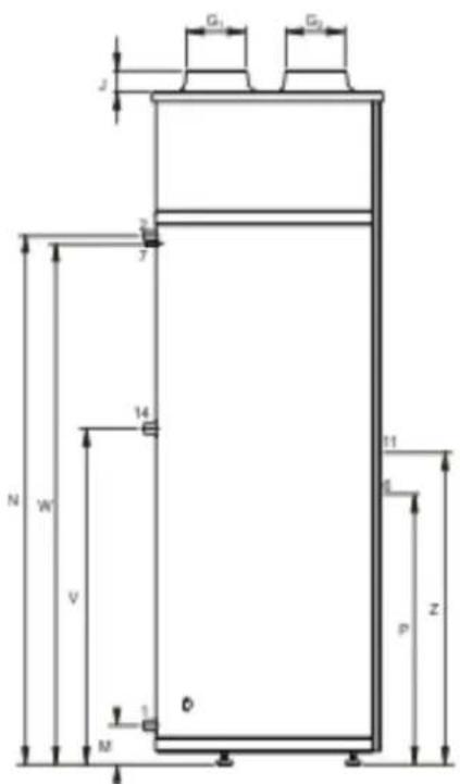
1.5.2 Dimensions

text_image
Hb2 Hb1 T Z Hy1 Hy2Dimensions (all measurements are in mm, except when indicated other wise)
| Description AHD 290 | ||
| A Total height 1815 | ||
| B Height of top of appliance 1790 | ||
| D Appliance diameter 660 | ||
| G1 Air inlet diameter 160 | ||
| G2 Air outlet diameter 160 | ||
| H Height air in-/outlet 1815 | ||
| Hx1 y-position air inlet | 190 | |
| Hx2 y-position air outlet 480 | ||
| Hy1 y-position air inlet | 200 | |
| Hy2 y-position air outlet 470 | ||
| J | Height air inlet | 60 |
| M | Height of cold water supply | 110 |
| N Height of hot water outlet | 1410 | |
| P Height of cleaning opening | 45 | |
| V Height of recirculation connection | 820 | |
| W | Height condensation drain | 1345 |
| Z | Height of electric element connection | 925 |
| 1 | Cold water supply connection (male) | R 3/4" |
| 2 | Hot water outlet (male) | R 3/4" |
| 6 | Cleaning/inspection opening | ∅ 110 |
| 7 | Condensation drainage connection (female) | ∅ 12 |
| 11 | Electric element connection (female) | G 1 1/2" |
| 14 | Recirculation connection (female) | R 3/4" |
text_image
G₁ G₂ J 2 7 14 N W V M D 11 6 p Z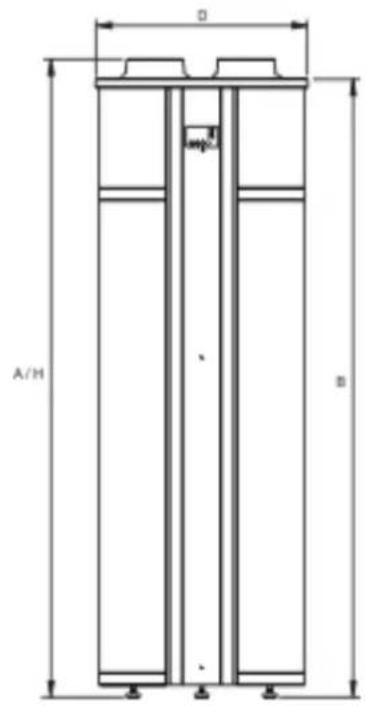
text_image
A/H B1.5.3 Water circuit – hydraulics diagram
UNVENTED
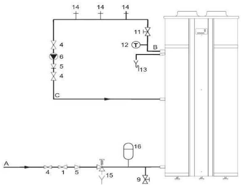
flowchart
graph TD
    A["Component A"] --> 4["Valve 4"]
    4 --> 1["Valve 1"]
    1 --> 5["Valve 5"]
    5 --> 15["Valve 15"]
    15 --> 9["Valve 9"]
    9 --> 16["Control Unit 16"]
    16 --> B["Component B"]
    B --> 12["T"]
    12 --> 11["Valve 11"]
    11 --> 13["Valve 13"]
    13 --> C["Component C"]
    C --> 4
    style A fill:#f9f,stroke:#333
    style B fill:#ccf,stroke:#333
    style C fill:#cfc,stroke:#333
VENTED
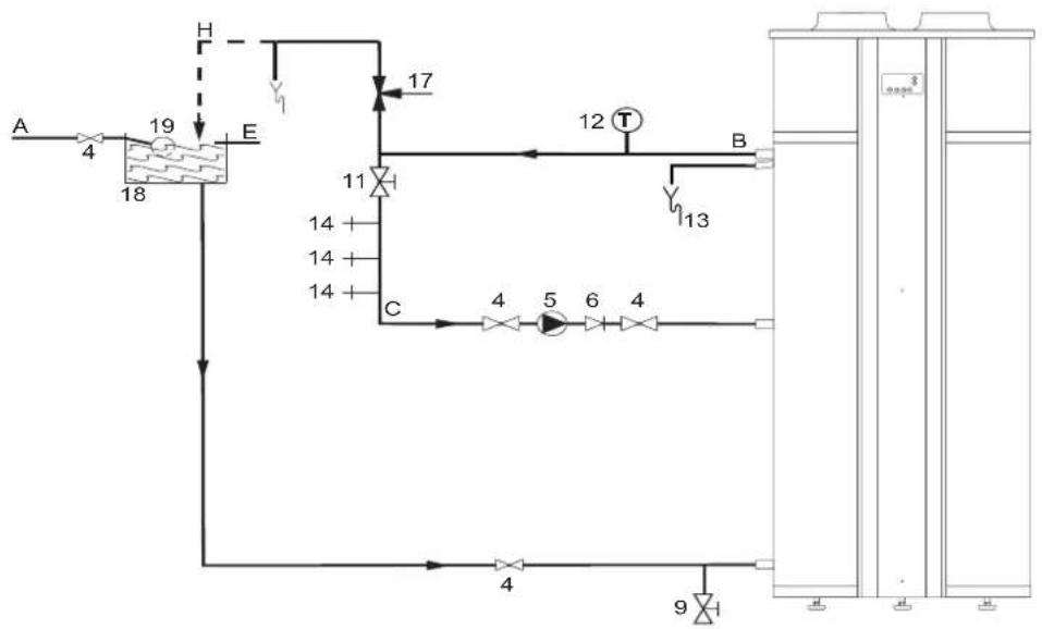
flowchart
graph TD
    A["18"] -->|4| B["19"]
    B -->|H| C["17"]
    C --> D["12 T"]
    D --> E["13"]
    E --> F["4"]
    F --> G["5"]
    G --> H["6"]
    H --> I["4"]
    I --> J["9"]
    J --> K["10"]
    K --> L["11"]
    L --> M["14"]
    M --> N["14"]
    N --> O["14"]
    O --> P["14"]
    P --> Q["14"]
    Q --> R["14"]
    R --> S["14"]
    S --> T["14"]
    T --> U["14"]
    U --> V["14"]
    V --> W["14"]
    W --> X["14"]
    X --> Y["14"]
    Y --> Z["14"]
    Z --> AA["14"]
    AA --> AB["14"]
    AB --> AC["14"]
    AC --> AD["14"]
    AD --> AE["14"]
    AE --> AF["14"]
    AF --> AG["14"]
    AG --> AH["14"]
    AH --> AI["14"]
    AI --> AJ["14"]
    AJ --> AK["14"]
    AK --> AL["14"]
    AL --> AM["14"]
    AM --> AN["14"]
    AN --> AO["14"]
    AO --> AP["14"]
    AP --> AQ["14"]
    AQ --> AR["14"]
    AR --> AS["14"]
    AS --> AT["14"]
    AT --> AU["14"]
    AU --> AV["14"]
    AV --> AW["14"]
    AW --> AX["14"]
    AX --> AY["14"]
Legends
Only applicable numbers are mentioned.
- pressure-reducing valve (mandatory if the mains water pressure exceeds 8 bar)
- stop valve (recommended in pipe C and mandatory in pipe A)
- non-return valve (mandatory)
- circulation pump (optional)
- drain valve (mandatory)
- service stop valve (recommended)
- temperature gauge (recommended)
-
condensation drainage (mandatory)
-
hot water draw-off points
- expansion valve (mandatory)
- expansion vessel (mandatory)
- 3-way aeration valve (recommended)
- water tank
- float valve
A. cold water supply
B. hot water supply
C. circulation pipe
E. overflow pipe
H. overflow safety
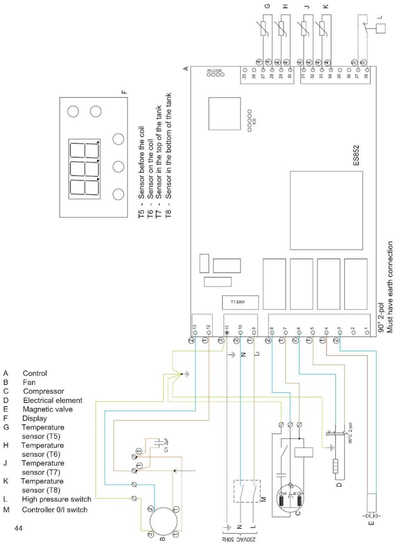
text_image
M L K J H G F E D C B A 44 Control M High pressure switch Controller 0/1 switch B ① ① ① C1 2µF Temperature Sensor (T7) Sensor (T6) Sensor (T5) Temperature Display Magnetic valve Electrical element Compressor Fan T5 - Sensor before the coil T6 - Sensor on the coil T7 - Sensor in the top of the tank T8 - Sensor in the bottom of the tank Z405 N L M N L1 C R D 90°C 2-pol E 90° 2-pol Must have earth connection ES852 PC.COM ICD A 25 26 27 28 29 30 31 32 33 34 35 36 37 38 G H J K L2. Before Installation /
Placement into
service
Deliverance
Heat pump including controller Installation manual with technical data User manual for controller
2.1 Important safety instructions
In the design and implementation of the heat pump, all relevant EU guidelines have been adhered to.

text_image
Work on the heat pump may only be performed by trained personnel! Take all necessary precautions in order to avoid accidents while working!2.1.1 Cooling system – safety instructions
The trained repairman must see to it that parts containing the refrigerant are emptied to a level at which the execution of the work can occur in a responsible manner without any dangers, before the commencement of repairs and service work.
When repairing and servicing the heat pump with the refrigerant system opened, and particularly for work with an open flame (soldering, welding, etc.), precautions must be taken to prevent fires from starting.
2.1.2 Electrical circuit – safety instructions

text_image
When working on the heat pump, the main supply must always be disconnected – pull the plug out!When connecting the heat pump to the power supply, the local and national rules and norms must be adhered to. In addition, regard must be paid to possible requirements posed by the energy supplier.
2.1.3 Water circuit – safety instructions
Only drinking water quality water may be used. During installation, regard must be paid to the choice of materials and it must be ensured that they can work together without problems in the entire circuit.

text_image
Special attention must be paid when using galvanized components and components containing aluminum!Safety equipment must be installed to prevent over pressure in the system.
All pipe work must comply with water safety regulations.
2.2 Delivery
The heat pump is delivered without water, condense water tube and the safety equipment for the water circuit.
2.3 Storage
The heat pump must be stored upright without water and in its packaging.
2.4 Transport
When carefully transporting the heat pump over short distances, it can be tilted up to 45^ C. If this limit is exceeded, the heat pump must stand in its normal upright position for at least 1 hour before it may be started.
Transport and storage may take place at temperatures between -10 and +50 °C. The heat pumps top / casing is not suitable for lifting with and must be carefully avoided during transport.
2.4.1 Transport with forklift
For transport with a forklift, the heat pump must stand on the associated transport frame. Always lift it slowly. Due to the high position of the centre of gravity, the heat pump must be secured against tipping during transportation.
2.4.2 Unloading the heat pump
In order to avoid damages, the heat pump must be unloaded on a flat surface.
2.4.3 Transport with trolley
The heat pump may only be transported on an associated transport frame. The heat pump must be secured against sliding on the trolley.
Water connections, etc., may not be used for transportation purposes.
Make sure that the trolley does not damage the cabinet and the connections.
2.5 Placement /set-up
The heat pump may only be installed in a frost-free room.
The installation location should comply with the following criteria:
• Room temperature between 0 and +35°C.
- Drain possibility for condensate water.
- No abnormal dust concentration in the air.
• Solid base (approx. 500 kg/m²)
- To achieve problem-free functioning and to allow access for service, it is recommended that 0.5m free space be maintained around the unit.
Set-up sequence:
- Remove the packaging from the pallet.
- Remove the transport fittings from the pallet.
- Take the heat pump off the pallet and place it at the desired location.
Adjust the heat pump vertically by adjusting the feet.
2.6 Connection of water pipes
During installation the actual pressure and pressure losses must be taken into account regarding pipe dimensions to assure sufficient pressure and water flow rates.
The plumbing must be carried out according to regulations.
The piping can be made of flexible or solid materials. Care must be taken in respect to corrosion to avoid damages.
As for all pressurerized containers the heat pump must also be equipped with safety and check valves on the supply side.
Cold water inlet and hot water outlet is located under the tank (3/4" thread connectors).
The maximum working pressure is 10 bars, and the maximum working temperature is 65°C.
If necessary, the supply pipe must be equipped with a pressure reduction valve and eventually a filter.
When installing the pipe work in the house any dirt in the pipes must be avoided. (Eventually flush the pipes with clean water before the heat pump is installed)!
When the pipes are connected make sure the pipes are not twisted. Use tools to hold the pipes against twisting!
If no recirculation is needed make sure the recirculation connector is closed!
Water connection
Under the heat pump the connections are located:
Condense water drain hose
Cold water inlet / Recirculation / Hot water outlet


natural_image
Close-up of a wooden floor with metal screws and a white toilet cover (no text or symbols visible)- Screws to be removed (hexagonal head).

natural_image
Close-up of wooden beams with visible wear and a small blue object on the surface (no text or symbols)- Screws to be removed.

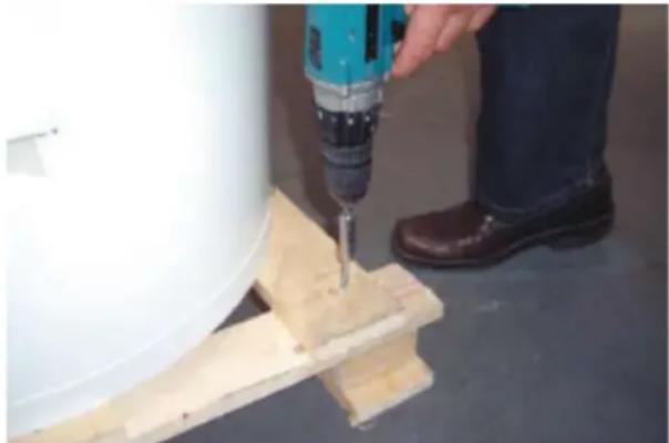
natural_image
Person using a power drill to cut or apply wooden blocks on a wall (no text or symbols visible)- Removal of screws.
natural_image
Exterior view of a modern office building (no signage)- Removal of product :
a: Glide product carefully to one side a bit.
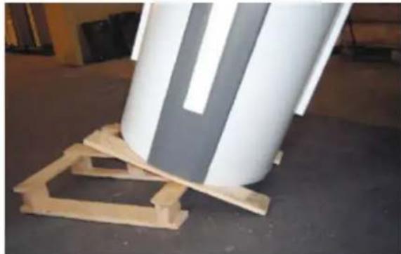
b: Bow over to the same side together with 2 pcs. of wood beneath.
natural_image
Wooden pallet with a large white cylindrical object on top, person standing nearby (no visible text or symbols)- Carry on with removal :
c: Remove the lower part of the palette while keeping the product in an angle position, still with 2 pcs. wood beneath
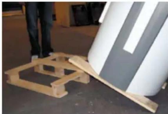
natural_image
Exterior view of a modern office building (no signage)- Product on floor with 2 pcs. of wood.
natural_image
Person standing beside a large cylindrical device on a wooden floor, with wooden pallets and a small object nearby (no visible text or symbols)- Removal of 1st piece of wood (can be released if product bowed a bit to one side).
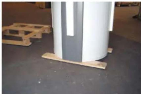
natural_image
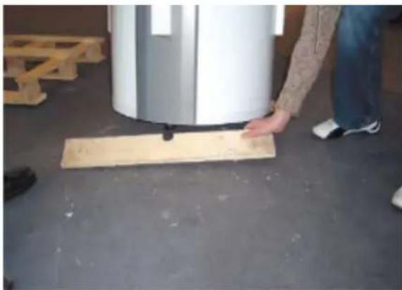
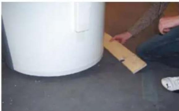
Person sitting on a floor next to a large white cylindrical container, with a wooden board visible (no text or symbols)- Removal of 2nd piece of wood (bow the product a bit to another side to release it).

natural_image
Close-up of a white cylindrical container with a side protrusion, placed on a dark surface (no text or symbols visible)- Palette removed.
3. Installation
3.1 Water connection
During installation, regard must be paid to the dimensions of the pipes with respect to the pre-existing water pressure and the pressure loss in order to ensure sufficient pressure and water flow rates at the draw-off point.
The maximum working pressure is 10 bars, and the maximum operating temperature is 65^ C. If necessary, the supply pipe must be equipped with a pressure reduction valve and possibly a filter.
As for all pressure vessels, the heat pumps connections must also be equipped with an approved safety valve on the service side and an approved check valve on the supply side.
All pipe work must comply with water safety regulations
3.2 Placement of pipe connections
Hot water outlet is mounted on the upper connecting branch. ( 34 " RG)
If the unit is used with the circulation of the hot water supply, the middle connecting branch is used as a return path. ( 34 ” RG)
Inlet of fresh cold water is mounted on the bottom connecting branch. (3/4" RG)
It is recommended to use 34 " flex tube for the connection of the water connection, to avoid possible sound from the vibration.
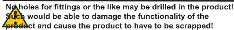
text_image
No holes for fittings or the like may be drilled in the product! Such would be able to damage the functionality of the product and cause the product to have to be scrapped!3.3 Connection of condensation drain
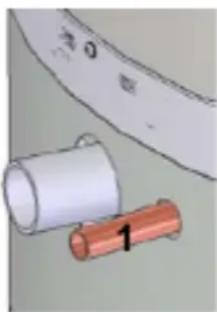
While the heat pump is running, some condensation water will occur, which is conducted to the drain connecting branch (1).
The quantity of condensation water depends upon the humidity of the air going through the inlet to the heat pump.
The condensation connecting branch must be equipped with a hose with a tight air trap, and run to a drain. The air trap must contain a water column of at least 60 mm.
It is also possible to use other tight air traps, like a tube with one turn.
natural_image
Illustration of a cylindrical object with a copper rod and a white cylindrical body, next to a curved surface (no text or symbols)
text_image
60 mmIf mounting of the air trap is omitted, water damage or damage to the heat pump can arise! If the air trap is not correctly mounted, the warranty will not apply!
3.4 Air intake and exhaust
Make sure that there is sufficient free space around the heat pump.
Inlet air
The inlet air may not be polluted with aggressive components (ammonia, sulphur, chlorine, etc.). Parts in the system may be damaged.
Air connectors
Inlet and outlet ducts must be made of smooth pipes to minimize pressure losses. Consider the fan working pressure and the duct resistance during installation. (See technical data.)
It is advised to install the air ducts that are placed near the heating pump, levelled or with a light fall towards the extract air outlet to avoid leaking of condensed water, easy to cut of. This will avoid leaking of condensed water from the ducts. When air ducts are placed outside the building the back pressure valve (with a small resistance) should be placed to ensure no cold air is entering the room in the winter time and when the heating pump is standing still.

heating pump may only be used with the tank filled up!

text_image
The unit must always be disconnected from the power before the front door is removed. When the unit is disconnected from the power please wait until the fan has stopped before opening the front doors!
text_image
Before starting up the unit please ensure that all cables and electric plugs are connected correctly and the cable and plug between the display in the door and the circuit board are connected!It is advised to insulate all ducts to lower heat loss and to lower the noise level.
3.5 Checking
After the installation, it is recommended that the checks be performed to ensure that the connections are sealed and that the drainage of the condensation water is unobstructed.
4. Placement into service / operation
The heat pump may only be started with a full water tank!
The unit must always be disconnected from the power supply when the front cover is opened!
When the unit is disconnected, wait for the fan to stop completely before the cover is opened!
Before starting the unit makes sure all connectors are in place, and make sure the cable between display and controller is mounted correctly!
4.1 Demands to the hot water circuit
In the hot water system the following materials may be used:
- Copper
- Stainless steel
- Brass
- Plastics
Depending on the used materials in the water circuit (in the house) wrong combinations of materials may lead to corrosion damages. Special attention is required when using galvanized steel or aluminium materials.
4.2 Starting to use the water circuit
- Fill the tank using the valve on the supply line, and let the air out through one of the upper hot tap water valves until air no longer is present in the tapped water.
- Check the entire water circuit for tightness.
- Connect the heat pump to the power supply.
After starting to use the system the entire water circuit must be checked for tightness.
4.3 Placement into service of the water circuit
Fill the container via the connecting branch, and aerate the tank by letting one of the hot water taps located at the highest elevation within the dwelling stand open until air no longer comes out with the water.
The container can normally hold 285 litres of water.
Check the entire circuit to be sure it is sealed.
4.4 Electricity – connecting
Connect the heat pump to the public electrical grid.
4.5 Cooling circuit
The cooling circuit is delivered ready to run and no work need be performed on it. The electronic controls automatically take over all functions concerning the operation of the compressor as well as the ventilator.
If needed, set the controls to the desired water temperature. The factory setting is 50^ C (see the operating instructions for more detailed directions).
4.6 Hints for energy savings
Do not set the water temperature higher than necessary.
The best utilization of the heat pump occurs at low water temperatures.
The use of circulation will increase the energy consumption of the heat pump significantly.
4.7 Hints for fan operation
When using ductwork it may be necessary to run the fan on a higher speed to compensate for the pressure losses.
4.8 Checking
After completing installation it is advised to check all connections etc. to ensure they are tight and to check that condensate water can flow to the drain unrestricted.
For servicing, please refer to user manual.
B
1. User guide
The AHD 290 comes with a factory setup, which enables an immediate start of the unit. The factory setup is basic and must be adjusted to the operational requirements and demands of the individual home, in order to obtain the optimum operating benefit from the unit.
1.1 Use

text_image
51.7 AO SmithUser menu
The value of a menu item is shown when pressing the key/key combination below. The value may be changed with the arrows when the key/key combination is held down simultaneously. The control will return to standard indication if no buttons have been pressed for app. 15 seconds.

P1: Heat Pump ON/OFF
On this button it is possible to change the function between: standby and automatic operation after setpoint P3. (step 0, step 1) Step 0: The heat pump is now off and only the control is active.
Step 1: The heat pump is in operation mode and drives after setpoint thermostat P3.

P2: Operation for the electrical cartridge
The heat pump comes with an extra electrical cartridge for heating of the sanitary hot water. On this button it is possible to turn on the electrical cartridge if required. By adjusting the setpoint to 1 the electrical cartridge will turn on after setpoint P5 (operating thermostat for the electrical cartridge). The electrical cartridge is not on if this setpoint it set to 0.
Note! When the ambient temperature is under 8^ C or over 35^ C the electrical cartridge will turn on even if P2 = 0.

P3: Operating thermostat for heat pump
The required sanitary water temperature may be set between 0 - 55°C, which is heated up by the heat pump.
Factory setting: 52°C
Max. water temperature: 55°C
P4: Stop defrosting
The level and operating thermostat buttons are pressed simultaneously
As a standard setting, the defrosting period ends when the temperature has reached 10^ C. During extraordinary operating conditions, it may be necessary to change this temperature. The temperature may be adjusted between 0-25^ C.
Factory setting: 10°C

P5: Operating thermostat for electrical cartridge

The sanitary water temperature may be adjusted between 0 - 65°C. The electric cartridge solely heats the top half of the container, while the heat pump still heats the lower half of the container.
Factory setting: 50°C

Display indication
It is possible to view various temperatures in the display, by pressing the arrows until the required temperature has been shown.

After app. 5 seconds, the temperature is shown. The temperature is shown for app. 30 seconds until the display returns to standard. Following temperatures may be shown:
T4: Extra sensor for free use or forced operating input
T5: Pre cooling surface
T6: Cooling surface
T7: Domestic water top
T8: Domestic water bottom
T9: Extra sensor
1.2 Altering of the operation data
Usually, the display shows the water temperature.

text_image
51.7 AO SmithPress (arrow up) and (arrow down) simultaneously for app. 10 seconds in order to enter the operating menu. To show the chosen value press The display will now show the first point E0 in the operating menu. The operating menu will close and return to the main menu if a button has not been pressed for 15 sec.
If you wish to scroll through the operating menu, it may be done by pressing (arrow up) or (arrow down). The value of a point is shown when pressing (temp button). The value may be changed with the (arrow up) or (arrow down) while simultaneously pressing (temp button). The control will return to standard indication if no buttons have been pressed for app. 15 seconds.
1.3 Operating menu
E0: Factory default
If the system does not function as expected, even though the set points have been adjusted, and the cause is impossible to locate, it is
recommended to note down the settings in the schedule. Thereafter the set point must be adjusted to 1 and wait until the control returns to standard settings. Now all the set points have been changed to the factory default. It is now possible to start all over and adjust the set points.
Factory setting: 0
E2: T9 set temperature
This sensor is able to control the relay R9, which will be activated when the set-point E2 is reached. The R9 relay can be used to control the three way damper of the exhaust air. This three way damper can supply the living area with cool air, if the room temperature reach the setpoint E2. For this function you will need a separate sensor, which is not a within the standard delivering. The sensor shall be connected to the control panel. For access to the control panel you have to dismantle the top of the machine.
E2 can be set between 10-30°C
Factory setting: 21°C
E8: Disinfection function ON/OFF
By setting the point to 1, the electric cartridge will provide 65^ C hot water, once a week, in order to disinfect the tank (legionella protection function).
Factory setting: 0
E9: Operating in cold surroundings ON/OFF
If the setting is 0, the heat pump will run as long as there is a need of heat (= exhaust air-operation).
Using the heat pump when taking the admission air from e.g. the cellar, there is an option of making the compressor stop in case the room is getting to cold. Instead, the electric heater will heat the water. The function is activated when the value has been set to 1 (= circulating air-operation).
It is also possible to automatically let the electrical heater help heating the water when the intake air temperature is below the temperature set in E10. The function is activated when the value has been set to 2 (= fresh air operation). If the value is 0, the function is not active.
Factory setting: 0
E10: Operating in cold surroundings
When activating the function menu E9, the temperature at which the compressor will stop, or the heater will assist, may be set. The temperature is adjustable between -10 and +10°C.
Factory setting: -5
E15: Hygrostat / stop unit
If the value is 0, the speed of the fans will change to 3 when the relative humidity is above the preset value of the hygrostat. If the value is 1, the unit will stop when the clips 25 and 26 are short-circuiting.
Factory setting: 0
E16: Min. airflow
This value shows the minimum speed at which the fan is permitted to run when operating. Notice that the cooling system may be overloaded, resulting a drop out of the high-pressure switch, if the value has been set too high. The value should not be chosen higher than necessary, in order to secure a minimal airflow through the cooling coil. Adjust this value between 0-100%.
Factory setting: 0
E17: Extended airflow ON
At 3rd speed, there is an option of making the unit step down automatically to the 2nd speed, after a number of hours, by adjusting to set 1. If the setpoint is adjusted to 0, the unit will run at the 3rd speed until a lower speed has been selected manually.
Factory setting: 0
E18: Hour
If automatic step-down at 3rd speed is in use, the number of hours at which the unit is to operate with forced air, may be adjusted here. The setpoint may be adjusted between 1 - 10 hours.
Factory setting: 3
E19: Extra function
If the setpoint is 1 the extra function will be activated as soon as T9 reach the setpoint (se E2). If the setpoint is 0, the function will be out of order.
E21: TX set
In order to avoid high operating pressures in the cooling system, the system output must be reduced for the remaining part of the heating period. This parameter indicates the water temperature at which the reduction should start. It may be set to 0-55°C.
Factory setting: 50
E23: Tmop
This value indicates the maximum permitted evaporation temperature. This prevents overloading of the compressor system at high ambient temperatures.
Adjust this value between 0-25°C.
Factory setting: 25
E25: Vent level 2
If an extended period of extraction from the building is wanted, it is possible to change to level 2. The fan will now run until another level has been selected.
This option is used to set the speed at which the fan should run, when level 2 is selected. Please note that this setting also sets the maximum fan speed when running in level 1. The speed may be set to 0-100%.
Factory setting: 100
E26: Vent level 3
If extraction from the building at a specific length of time is required, it is possible to change to level 3. The fan will now run for the set period. Thereafter the system will return to level 2. This menu option is used to specify the speed at which the fans should run when the set period has been chosen. Please note that this setting also sets the maximum fan speed when running in level 1 The speed may be set to 0-100%.
Factory setting: 100%
E27:
Available function. Must at all times be 1.
E45: dTair-set
Here it is possible to choose minimum cooling of the air, while heating the water. The control will adjust the speed of the fan to make sure the air will be cooled at the exact temperature chosen. In case the control needs to cool the air due to technical reasons, the value will be controlled by the automatic function. When requiring a higher fan speed, the value may be reduced. Remember though, the fan will run faster, using more energy, if the values are set to low.
Factory setting: 1
1.4 Factory default scheme
| Factory default scheme Date Date | |||
| E0 : Factory default 0 0 | |||
| E2: Set temperature | |||
| E8 : Disinfection function ON/OFF 0 | |||
| E9: Operating in cold surroundings | |||
| E10: Operating in cold surroundings | |||
| E15: Hygrostat/ stop unit | |||
| E16 : Min. air flow 0 | |||
| E17: Forced ON | |||
| E18: Hours | |||
| E19: Extra function | |||
| E21 : TX-set 50 | |||
| E23 : Tmop 25 | |||
| E25: Vent level 2 | |||
| E26: Vent level 3 | |||
| E27: | |||
| E45 : dTair set 1 | |||
1.5 Defrost program
Use of hot tap water heat pump:
The heat pump is only intended to produce hot tap water for domestic use within the specified temperature limits. The sanitary hot water heat pump is a complete unit with a 285 litre hot water tank, extraction fans, heat pump and also equipped with a complete electrical equipment and five models are equipped with a heating coil.
Capacity:
The heat pump is capable of producing a hot water volume of app. 1000 Litres at 45^ C. The actual volume depends on the supplied fresh water temperature, air temperature and the pattern of use of hot water. The additional electrical heating element (1,5 kW) may be used to boost the capacity whenever needed. The heat pump only uses app. 27% of the energy compared to a conventional electric boiler.
Heat pump operation:
The control starts the compressor shortly after hot water has been tapped. The compressor will run until the entire tank has been heated to the set temperature again. Usually the heat pump can produce a sufficient amount of hot tap water covering the needs of a common family.
Water heating:
When hot water is drawn off, the tank will be refilled with cold water at the bottom. A sensor measures the temperature at the bottom of the tank and starts the compressor if the temperature has fallen 5^ C below the set temperature. The compressor stops, when the water has been heated to the set temperature. While the compressor operates, the fans run and circulate air through the cooling surface.
Fan operation:
The fan may be set to run continuously, when the compressor has stopped - by selecting level 2 or level 3. This option may be chosen when the heat pump is used as an extraction system in the residential wet rooms. If the input to T4 short circuits, the control is forced to run at 3rd speed. This may be used in order to achieve more extract in e.g. bathroom, while taking a shower. When breaking the short circuit on the input pins to T4, the control will return to its previous step.
Defrosting:
When the temperature difference between the temperature upstream of the cooling surface and the temperature of the cooling surface becomes too large (as happens when ice is formed on the cooling surface), the unit goes into defrost mode. The magnetic valve MA 4 opens and the supply air fan stops until the ice has melted and the cooling surface has reached a temperature of app. 5°C. Then the magnetic valve closes again and the supply air fan resumes operation.
2.2 Extra capacity
If a situation should occur where the heat pump is not capable of producing enough hot tap water (more people in the house), an extra electrical cartridge in the container can be switched on. Doing so, it is possible to heat up more water. It is possible to set the desired temperature to which the electrical cartridge should heat up the water. (Only use the electrical cartridge when needed, as it uses more energy than the compressor). The electrical cartridge can be activated manually on the display.
2.3 Operation safety
High-pressure switch:
To prevent the compressor from exceeding its range of operation, there is an integral high-pressure switch, which interrupts when the pressure is 20 bar in the cooling unit. Activate the red reset button once the cause of the error has been identified. When the high-pressure switch interrupts, the red LED will flash until the reset button manually or the pressure has fallen to 15 bar or the cause of error has been identified. When the high-pressure switch interrupts, the red light will flash until the reset button on the pressure switch is activated. In order to prevent a repetition of a pressure switch error, the water may be set 2-3°C lower.
Safety breaker for electrical heating element
If an error occurs at the heater, the safety breaker trips and stops the heater in order to prevent the tank from being overheated.
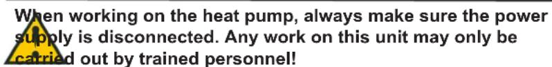
text_image
When working on the heat pump, always make sure the power supply is disconnected. Any work on this unit may only be carried out by trained personnel!2.4 Warnings
High-pressure switch:
When the pressure switch trips, the red light on the display will light until the pressure switch is reset.
3. Maintenance
The following instructions must be followed in order to ensure optimum operation of the heat pump.

power supply to the system must always be switched off before hing the heat pumps cover.
When the unit has been installed for the first time make sure the water connections are checked after a few days to make sure there are no leaks. Also check that the condensate drain pipe is not blocked.
Environmental considerations
When the unit is being serviced or its operation is cancelled, please make sure to follow the guidelines for recovery and disposal of all materials according to local procedures and laws.
3.1 Cooling system and fan
Fan:
Maintaining the fans is mainly periodically cleaning of the evaporator.
Disconnect the flexible hoses from the top of the unit and unscrew the top plate.
Clean the fan with a suitable brush. Do not remove the balancing blocks from the impeller, as this will cause imbalance and with it more noise and fan wear.

of injury from sharp-edged fins! Do not damage this fins!
Condensate drain:
When changing the filters in the autumn season, check the condensate drain and tray for blockage by dirt. Fill water in the condensate tray and check that the water runs out unhindered. Should this not be the case the drain must be cleaned. At the same time make sure that the plates of the evaporators are clean.
3.2 Water circuit and tank
Safety valve:
The installer has fitted a safety valve on the cold water supply pipe for the hot water tank. This valve is a protection of the tank against excess pressure when the domestic water expands during heating. The non-return valve, which is fitted before the safety valve on the cold water pipe, prevents the water from flowing back into the cold water pipe. This means that the pressure in the tank will increase to the maximum pressure permitted by the safety valve, at which point it will open and allow the surplus water to escape. If the safety valve did not open, the tank would burst.
To make sure that the safety valve is working properly, it should be inspected several times a year. To do this, press the spring-loaded arm on the safety valve and see if water comes out of the valve. Damage caused by a blocked safety valve is not covered by the Genvex warranty.
Anode:
In order to prevent corrosion of the enamelled hot water tank, the tank is fitted with a magnesium anode with a 34 " screw plug. This anode has a life expectancy of 2-5 years. It is nevertheless important to check that the anode is intact at all times. This should be done by inspecting the anode every 2 years and replacing it if it is corroded and measures only 6-10 mm in diameter. To inspect the anode, turn off the power supply to the system and remove the front cover. The hot water tank has to be drained before the anode can be unscrewed. To do this, turn off the cold water supply, attach a hose to the drain valve to ensure the water runs to the nearest drain. When draining the water from the tank, turn on a hot water tap to prevent negative pressure in the tank. When the tank is empty, the anode can be unscrewed and inspected. When the anode has been fitted again, close the drain cock and turn the valve water supply back on to fill the tank with water. When the tank is full and the cover back on, the power supply can be switched on again.
3.3 Demounting / Putting the unit out of service
The following actions must be taken:
Disconnect the power supply from the unit and disconnect other connections. Shut off the fresh water supply valve and connect a drain hose to the drain valve in order to drain the water. While draining, a hot tap water valve should be opened to avoid under pressure in the tank. The air duct connections are uninstalled and remaining air channels must be closed to avoid condense water entrance to the building.
4. Fault finding
The heat pump is equipped with the following safety devices:
4.1 High-pressure switch
To prevent the compressor exceeding its range of application, there is an integral high-pressure switch, which interrupts when the pressure becomes too high. In case of interruptions (too high-pressure), the red light in the control panel will flash and the high-pressure switch will stop the heat pump. The red light lights. Restart the equipment by manually resetting the high-pressure switch.
For manually resetting the high-pressure switch, the front door can be removed by releasing the screws.
For RESET, remove the plastic stopper at the top and press the red button.
4.2 Safety breaker for heating element
The safety breaker protects the equipment against overheating during heating with the electrical heating element. The safety breaker is mounted on the heater. If the adjusted value (90°) is exceeded, the heating coil will disconnect. It can be reconnected when the temperature is below 90°. To do this, the power to the equipment must be off. The reset button can now be pressed.
Please notice: Be careful not to damage or tear the cables to the control.
4.3 Heat pump will not run
Please test if:
• the power is connected;
- the power is turned on at the wall plug;
• the water temperature is at the setpoint;
- the temperature of the domestic water is less than 55^ ;
- the cable between controller and display is connected.
If this does not help locating the error, please contact your local installer or service contractor.
5. Garantie (certificat)
To register your warranty, you should complete and return the enclosed warranty card after which a warranty certificate will be sent to you. This certificate gives the owner of a appliance supplied by A.O. Smith Water Products Company B.V. of Veldhoven, The Netherlands (hereinafter "A.O. Smith") the right to the warranty set out below, defining the commitments of A.O. Smith to the owner.
General warranty
If within one year of the original installation date of a water heater supplied by A.O. Smith, following verification, and at the sole discretion of A.O. Smith, a section or part (with exclusion of the tank) proves to be defective or fails to function correctly due to manufacturing and/or material defects, then A.O. Smith shall repair or replace this section or part.
Tank warranty
If within 3 years of the original installation date of a water heater supplied by A.O. Smith, following inspection, and at the sole discretion of A.O. Smith, the glass-lined steel tank proves to be leaking due to rust or corrosion occurring on the water side, then A.O. Smith shall offer to replace the defective water heater with an entirely new water heater of equivalent size and quality. The warranty period given on the replacement water heater shall be equal to the remaining warranty period of the original water heater that was supplied. Notwithstanding that stated earlier in this article, in the event that unfiltered or softened water is used, or allowed to stand in the water heater, the warranty shall be reduced to one year from the original installation date.
Conditions for Installation and use
The warranty set out in article 1 and 2 will apply solely under the following conditions:
a. The water heater is installed under strict adherence to A.O. Smith installation instructions for the specific model, and the relevant government and local authority installation and building codes, rules and regulations in force at the time of installation.
b. The water heater remains installed at the original site of installation.
c. The appliance is exclusively used with drinking water, which at all times can freely circulate (a separately installed heat exchanger is mandatory for heating salt water or corrosive water).
d. The tank is safeguarded against harmful scaling and lime buildup by means of periodic maintenance.
e. The water temperatures in the heater do not exceed the maximum setting of the thermostats, which form a part of the water heater.
f. The water pressure and/or heat load do not exceed the maximum values stated on the water heater rating plate.
g. The water heater is installed in a non-corrosive atmosphere or environment.
h. The water heater is connected to a protected cold supply arrangement, which is: approved by the relevant authority; with sufficient capacity for this purpose; supplying a pressure no greater than the working pressure stated on the water heater; and where applicable by a likewise approved temperature and pressure relief valve, fitted in accordance with installation instructions of A.O. Smith applying to the specific model of water heater, and further in compliance with the government and local authority installation and building codes, rules and regulations.
i. The appliance is at all times fitted with cathodic protection. If sacrificial anodes are used for this, these must be replaced and renewed when, and as soon as, they are 60% or more consumed. When electric anodes are used, it is important to ensure that they continue to work properly.
Exclusions
The warranty set out in articles 1 and 2 will not apply in the event of:
a. damage to the water heater caused by an external factor;
b. misuse, neglect (including frost damage), modification, incorrect and/or unauthorised use of the water heater and any attempt to repair leaks;
c. contaminants or other substances having been allowed to enter the tank;
d. the conductivity of the water being less than 125 S/cm and/or the hardness (alkaline-earth ions) of the water being less than 1.00 mmol/litre;
e. unfiltered, recirculated water flowing through or being stored in the water heater;
f. any attempts at repair to a defective water heater other than by an approved service engineer.
Obligations of A.O. Smith
The obligations of A.O. Smith pursuant to the specified warranty do not extend beyond free delivery from the Veldhoven warehouse of the replacement sections, parts or water heater respectively. Shipping, labour, installation and any other costs associated with the replacement will not be accepted by A.O. Smith.
Claims
A claim on grounds of the specified warranty must be submitted to the dealer from whom the water heater was purchased, or to another authorised dealer for A.O. Smith Water Products Company products. Inspection of the water heater as referred to in articles 1 and 2 shall take place in one of the laboratories of A.O. Smith Water Products Company.
Scope of the warranty
A.O. Smith grants no other warranty or guarantee over its water heaters nor the (sections or parts of) water heaters supplied for replacement, other than the warranty expressly set out in this Certificate.
Under the terms of the supplied warranty, A.O. Smith is not liable for damage to persons or property caused by (sections or parts, or the glass-lined steel tank of) a (replacement) water heater that it has supplied.
A.O. Smith Water Products Company
Case postale 70
5500 AB Veldhoven
Pays-Bas
Téléphone (gratuit) 008008 - AOSMITH 008008 - 267 64 84
Général: +31 40 294 25 00
Fax: +31 40 294 25 39
E-mail : info@aosmith.nl
text_image
G₁ G₂ J 2 7 14 N W V 1 M 0 6 11 P Z
text_image
D E A / H B H1 H2 H32.5 Placement / disposition
natural_image
Close-up of wooden blocks with metal fixtures and a white toilet cover, no visible text or symbolsnatural_image
Close-up of wooden construction materials with visible rebar and holes (no text or symbols)- Vis à retirer.
natural_image
Person using a power drill to cut or repair a wooden block, no visible text or symbols- Retrait des vis.

natural_image
Large cylindrical object placed on a wooden pallet in a workshop (no visible text or symbols)- Dépose du produit :
natural_image
Wooden pallet with a large cylindrical object on top, person standing nearby (no visible text or symbols)natural_image
Exterior view of a modern office building (no signage)natural_image
Person standing beside a large cylindrical device on a wooden floor, with no visible text or symbols.natural_image
Person kneeling beside a large white cylindrical container with a wooden board, next to a dark floor (no text or symbols visible)natural_image
Close-up of a white cylindrical container with a small rectangular opening, placed on a dark floor (no text or symbols visible)- Palette retirée.
3. Installation
3.1 Connexion d'eau
natural_image
Illustration of a cylindrical object with a copper rod and a separate cylindrical component labeled '1' (no text or symbols on the objects themselves)
text_image
51.7 AO SmithMenu utilisateur
text_image
51.7 AO SmithObligations de A.O. Smith
Copyright © 2008 A.O. Smith Water Products Company
A.O. Smith Water Products Company
Postfach 70
5500 AB Veldhoven
Niederlande
Telefon: 008008 - AOSMITH
008008 - 267 64 84
Allgemein: +31 40 294 25 00
Fax: +31 40 294 25 39
E-Mail: info@aosmith.nl
Website: www.aosmithinternational.com
text_image
G1 G2 J Z 7 N W V 14 M O 11 P Z
text_image
A/H Bnatural_image
Close-up of a wooden plank with metal screws and a white container (no text or symbols visible)natural_image
Close-up of wooden beams and a small blue object on a surface (no text or symbols visible)natural_image
Person using a power drill to work on a wooden structure, no visible text or symbolsnatural_image
Large cylindrical object placed on a wooden pallet in a workshop (no visible text or symbols)natural_image
Wooden pallet with a large white cylindrical object on top, person standing nearby (no visible text or symbols)natural_image
Exterior view of a modern office building (no signage)natural_image
Person standing beside a large cylindrical device on a wooden platform in a workshop setting (no visible text or symbols)natural_image
Person sitting on the floor next to a large white cylindrical container, with a wooden board and a small white object nearby (no visible text or symbols)natural_image
Close-up of a white cylindrical container with a small rectangular opening, placed on a dark surface (no text or symbols visible)natural_image
Two cylindrical objects, one white and one reddish-brown, placed on a plain background (no text or symbols visible)
text_image
51.7 AO SmithBenutzermenü