USER MANUAL 802.11g VIVANCO
This equipment complies with the requirements relating to electromagnetic compatibility, EN 55022 class B for ITE, the essential protection requirement of Council Directive 89/336/EEC on the approximation of the laws of the Member States relating to electromagnetic compatibility.
Company has an on-going policy of upgrading its products and it may be possible that information in this document is not up-to-date. Please check with your local distributors for the latest information. No part of this document can be copied or reproduced in any form without written consent from the company.
Trademarks:
All trade names and trademarks are the properties of their respective companies. Copyright © 2007, All Rights Reserved.
23414 WLAN ROUT 54-N
GB
Thank you for purchasing the product. Before you start, please check all the contents of this package.
The product package should include the following:
- One Wireless Router
- One power adapter
- One User Manual (CD)
- One detachable antenna
INTRODUCTION TO WIRELESS ROUTER
General Description
The Wireless Router built-in with 4-port 10/100Mbps Fast Ethernet Switch is the latest generation of Wireless router product for Home/Office and SOHO users. This full-feature and self-contained compact Wireless Router will be fully for broadband access in both of LAN and Wireless environment. This device has been specifically designed to provide LAN and Wireless users the most cost-effective method with multiple accesses to the Internet at the cost of a single public IP address (IP Sharing) and enjoy the true Plug-and-Play installation. Moreover, the built-in 4-port 10/100Mbps switch lets users plug the network cable into the device without buying additional switch.
This device is also an Access Point. It has a built-in wireless LAN. Users can connect to Internet using wireless network interfaces anywhere within the range of its radio transmission. It's ideal for SOHO users who require instant and convenient access to Internet without the restriction of connecting cables.
The friendly WEB-based graphics interface for setup makes any inexperienced users soon enter plug-and-play operation. Embedded DHCP server simplified IP address management and no MIS people needed for daily technical services. What is more, NAT/firewall is also implemented on this compact Router Box for protecting whole LAN from outside attack.
23414 WLAN ROUT 54-N
Key Features
The switch provides the following key features:
■ Complies with IEEE 802.11b/g wireless standards
■ Provides one 802.11b/g wireless Reverse SMA detachable antenna
■ High speed transfer data rate up to 54Mbps
■ Supports turbo mode for 72Mbps data transfer
■ Supports wireless data encryption with 64/128-bit WEP, WPA (TKIP with IEEE 802.1x), WPA2 and AES functions
■ Supports system log
■ Supports authentication for wireless connectivity based on ESSID
■ Provides MAC access control and hidden SSID function
■ WDS supported with WEP, TKIP and AES encryption
■ Channel: USA 11, Europe 13, Japan 14
■ Supports NAT/NAPT IP Sharing
■ Supports Static IP, PPPoE, PPTP, & DHCP client
■ SPI Anti-DoS Firewall; Virtual DMZ; DNS relay; UPnP
■ Provides DHCP server
■ Supports ALG for FTP, NetMeeting, DDNS (DynDNS, TZO)
■ Supports firmware upgrade function via Web
■ Compliant with FCC Part 15.247 for US, ETS 300 328 for Europe
■ Flash: 2MB NOR type, SDRAM: 8MB
■ Certifications: FCC Class B, CE Mark, VCCI Class B
23414 WLAN ROUT 54-N
The Front Panel

natural_image
Illustration of a device casing with a black cover and 'vivanco' logo, no readable text or symbols beyond the brand name.
LED definition
System LEDs
SystemelfED pinclonal for showing the operating status of the whole device.
- PWR (Power) LED
This indicator lights green when the Wireless Router is receiving power; otherwise, it is off.
- Status LED
The LED will be dark for a few seconds when the system is started. After that, the LED will blink periodically to show the Wireless Router is working normally. If the LED stays green/dark that means the system failed, you need to contact your agent or try to reboot the system.
Port LEDs (Wireless)
- WLAN LED
I. When system is ready for data transmitting and receiving, it is steady green.
II. When the data is transmitting or receiving, it is blinking green.
23414 WLAN ROUT 54-N
Port LEDs (WAN)
Port LED (WAN) indicators locate on the front panel for showing the operating status of WAN port.
- Act/Link LED
The LED stays light (green) means the port has good linkage to its associated devices.
The LED will blink green when there is traffic transverse the port.
Port LEDs (LAN)
Port LEDs (LAN) indicators locate on the front panel for showing the operating status of 10/100Mbps Fast Ethernet switching ports.
- Act/Link LED
Every port has a Act/Link LED. Steady green (link state) indicates that the port has good linkage to its associated devices. Flashing green indicates that the port is receiving or transmitting data between its associated devices.
The Rear Panel

text_image
DC 12V LAN4 LAN3 LAN2 LAN1 WIN Restore Default
Power Connection
Plug the circle end of the power adapter firmly into the rear panel of the Wireless Router, and the other end put into an electric service outlet then the system is ready.
Placement (Optional)
There are three ways to place the Router. The first way is to place the Router horizontally
ndon a surface.
the Router vertically on a surface. These options are explained in further detail below.
23414 WLAN ROUT 54-N
Desktop Option
- The Router has one plastic stand that can be divided into two parts.
- Combine one part of stand with the side of router.
- Do the same with the second part.
- Place the Router
Wall-mount option
Before attach this router on the wall, you have to finish the desktop option steps first.
- Select a location with access for cables and a power outlet.
- Oatpbugfrhse umid Phack itthepside dokers for a anchors.
- Installing the Wall mount anchor (plastic) into the wall with tools such as drill or hammer.
- Insert the provided screws in each hole of the stand parts.
- Attaches the unit to the anchors on the wall.
Stand Option
- The Router includes two stand parts.
- Combine two parts into one stand. Combine it with the side of router near the power port. Push the stand up to snap it into place.
- Place the Router.
- Push the button for more than 5 seconds and then release it, the system will return to factory default setting. In the meantime, system rewrites flash to default value and Status LED halts for a while. Approximately 60 seconds later, the Status LED blinks green periodically, now the whole system parameters have returned to factory default value. If the process has been interrupted by any reason (power off...), the system will fail. Before performing the process, ensure a safe operating environment please.
- To reboot the Router, Press the button for 2-5 seconds and then release it, and all the setting won't be erased. Wait for the Router to complete the reboot, and then you can start to use it.
23414 WLAN ROUT 54-N
Warning! Incomplete factory setting recovery procedure will cause the Wireless Router malfunction is situation and unfortunately repair it by yourself. Consult your local distributor for help.
INSTALLING AND USING WIRELESS ROUTER
This Chapter procedure step-by-step beside to the installati
Router. We suggest you go over the whole chapter and then do more advanced operation.
Network configuration setup
Steps to build up the network:
➢ ConCable the ADSL to the Ethernet WAN port on the back of the Wireless Router by using the UTP cable.
Connect the phone line from the wall socket to the line-in port on the ADSL modem, or the coaxial cable to the line-in port on the Cable modem.
Plug-in the power adapter to the modem and turn on the power. Install the Ethernet card into the computer by referring to the User Guide that came with the card.
Connect the computer to the Wireless Router by using standard twisted-pair Ethernet cable from the computer's Ethernet card to an 10/100Mbps Ethernet port on the back of the Wireless Router.
Plug-in the power adapter to the Router and the other side to the wall outlet.
23414 WLAN ROUT 54-N
Computer configuration setup
In order to communicate with this Wireless Router, you have to configure the IP addresses of your computer to be compatible with the device. The router supports DHCP server and it is enabled as default. Users that configure your IP address as “Obtain an IP address automatically” may skip the following IP configuration instruction.
Note:
- The default network setting of the device:
IP address: 192.168.1.1
Subnet Mask:255.255.255.0
DHCP Server: enabled
-
In the following TCP/IP configuration guide, the IP address "192.168.1.2" is assumed to be your IP address if you want to specify IP addresses manually. Please DO NOT choose 192.168.1.1 for the IP address (192.168.1.1) has been set as the default IP for this device.
-
The following TCP/IP configuration guide uses windows XP as the presumed operation system.
-
If you are in Classic Start menu view, click Start > Settings > Control Panel > Network Connections.
-
If you are in Start menu view, click Start > Control Panel > Network Connections.
-
Double click "Local Area Connection"
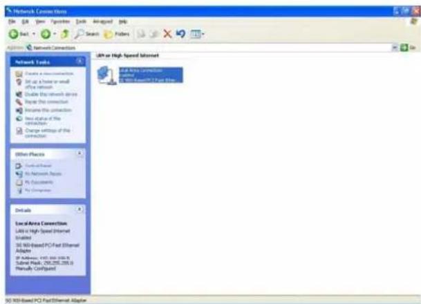
text_image
Network Connection
File Edit View Options Edit Advanced Help
Set - Search Filters
Network Connections
Network Tools
Create a new connection
Set up a home or small office network
Enable the network device
Prepare the connection
Improve the connection
Next status of the connection
Change settings of the connection
Other Places
Formal/Server
No Network Access
No Documents
No Computer
Details
Local Area Connection
Labs in High Speed Ethernet
Installed
30 WID-based PC Fast Ethernet Adapter
If Address: 149, 800, 200, 500, 700, 1000, 1200, 1500, 1800, 2000, 2200, 2500, 2800, 3000, 3200, 3500, 3800, 4000, 4200, 4500, 4800, 5000, 5200, 5500, 5800, 6000, 6200, 6500, 6800, 7000, 7200, 7500, 7800, 8000, 8200, 8500, 8800, 9000, 9200, 9500, 9800, 10000, 10200, 10500, 11000, 11500, 12000, 12500, 13000, 13500, 14000, 14500, 15000, 15500, 16000, 16500, 17000, 17500, 18000, 18500, 19000, 19500, 20000, 21500, 23500, 25500, 27500, 31500, 34500, 37500, 41500, 44500, 47500, 51500, 54500, 57500, 61500, 64500, 67500, 71500, 74500, 77500, 81500, 84500, 87500, 91500, 94500, 97500, 115553. www.widband.com/
LAN or High Speed Internet
LAN (LAN Connection)
LAN (LAN Connection) / LAN (LAN Connection) / LAN (LAN Connection)
23414 WLAN ROUT 54-N
- Choose Internet Protocol (TCP/IP) and click Properties.
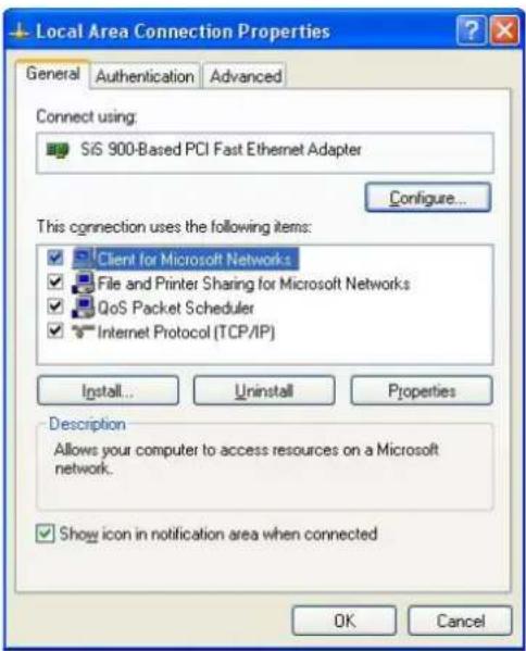
text_image
Local Area Connection Properties
General Authentication Advanced
Connect using:
SiS 900-Based PCI Fast Ethernet Adapter
Configure...
This connection uses the following items:
✓ Client for Microsoft Networks
✓ File and Printer Sharing for Microsoft Networks
✓ QoS Packet Scheduler
✓ Internet Protocol (TCP/IP)
Install... Uninstall Properties
Description
Allows your computer to access resources on a Microsoft network.
✓ Show icon in notification area when connected
OK Cancel
- You may choose "Obtain an IP address automatically"(recommend) to get IP address automatically or choose "Use the following IP address" to specify IP addresses manually. Please click the OK button after your configuration.
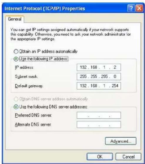
text_image
Internet Protocol (TCP/IP) Properties
General
You can get IP settings assigned automatically if your network supports this capability. Otherwise, you need to ask your network administrator for the appropriate IP settings.
Obtain an IP address automatically
Use the following IP address:
IP address 132 . 168 . 1 . 2
Subnet mask 255 . 255 . 255 . 0
Default gateway 132 . 168 . 1 . 254
Obtain DNS server address automatically
Use the following DNS server addresses:
Preferred DNS server: . . . .
Alternate DNS server: . . . .
Advanced...
OK Cancel
23414 WLAN ROUT 54-N
MANAGEMENT
Wireless Router configuration setup
In order to make the whole network operate successfully, it is necessary to configure the Wireless Router through your computer has a WEB browser installed. Please follow up the steps listed below.
- Double click the Internet WEB browser icon on your desktop screen (Netscape Communicator 4.0 and Internet Explorer 3.0 or update version)
- Type 192.168.1.1 into the URL WEB address location and press Enter.
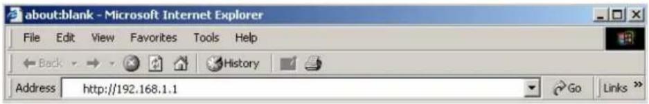
text_image
about:blank - Microsoft Internet Explorer
File Edit View Favorites Tools Help
Back History
Address http://192.168.1.1 Go Links »
-
The Username and Password Required window appears.
-
Enter admin in the User Name location (default value).
- Enter admin in the Password location (default value).
- Click "OK" button
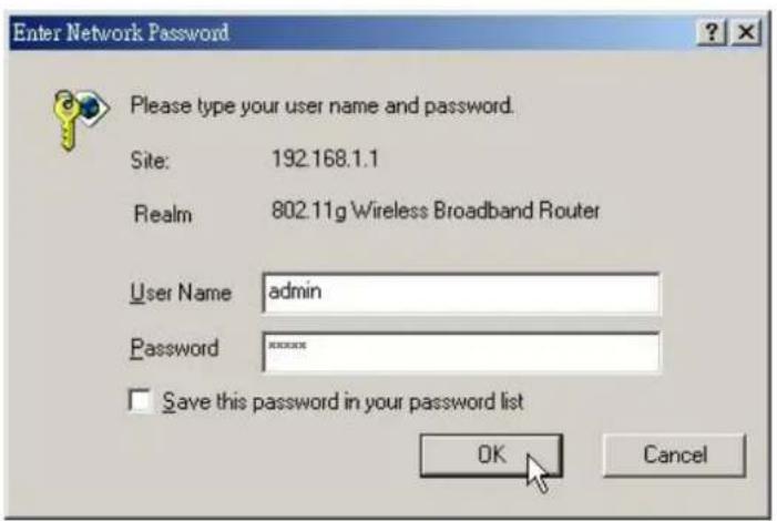
text_image
Enter Network Password
Please type your user name and password.
Site: 192.168.1.1
Realm 802.11g Wireless Broadband Router
User Name admin
Password ******
Save this password in your password list
OK Cancel
23414 WLAN ROUT 54-N
4. The Graphic User Interface
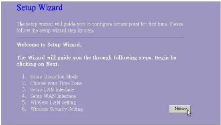
After the password authorization, the Setup Wizard shows up as the home page of the Graphic User interface. You may click on each folder on left column of each page to get access to each configuration page.

text_image
802.11g Wireless Broadband Router
Setup Wizard
The setup wizard will guide you to configure access point for that time. Please follow the setup wizard
stop by step
Welcome to Setup Wizard
The Wizard will guide you the through following steps. Begin by clicking on Next.
1. Setup Operating Mode
2. Choose Your Time Zone
3. Setup LAN Interface
4. Setup WAN Interface
5. Windows LAN Setting
6. Wireless Security Setup
Next>
23414 WLAN ROUT 54-N
Setup Wizard
If you are using the router for the first time, you may follow the procedures of the setup wizard to do a step-by-step configuration.
Note: The following instruction does an overall introduction to the Setup Wizard. For detail information to each item, please refer to instruction of each page.
- To start the Setup Wizard, click the "Next" button to proceed.
text_image
Setup Wizard
The setup wizard will guide you to configure access point for first time. Please follow the setup wizard step by step.
Welcome to Setup Wizard.
The Wizard will guide you the through following steps. Begin by clicking on Next.
1. Setup Operation Mode
2. Choose your Time Zone
3. Setup LAN Interface
4. Setup WAN Interface
5. Wireless LAN Setting
6. Wireless Security Setting
Next>
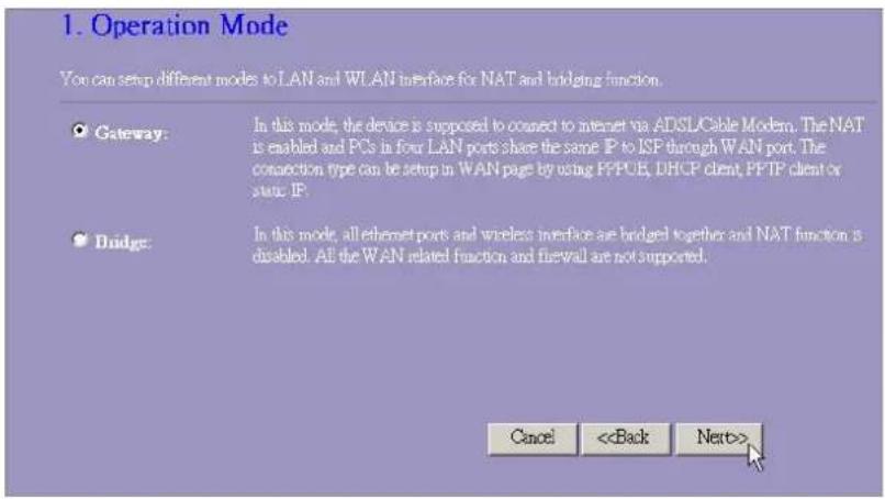
- Select your demanding operation mode and click "Next".
text_image
1. Operation Mode
You can setup different modes to LAN and WLAN interface for NAT and bridging function.
Gateway: In this mode, the device is supposed to connect to internet via ADSLCable Modem. The NAT is enabled and PCs in four LAN ports share the same IP to ISP through WAN port. The connection type can be setup in WAN page by using PPUE, DHCP client, PFTP client or state IP.
Bridge: In this mode, all ethernet ports and wireless interface are bridged together and NAT function is disabled. All the WAN related function and firewall are not supported.
Cancel <
23414 WLAN ROUT 54-N
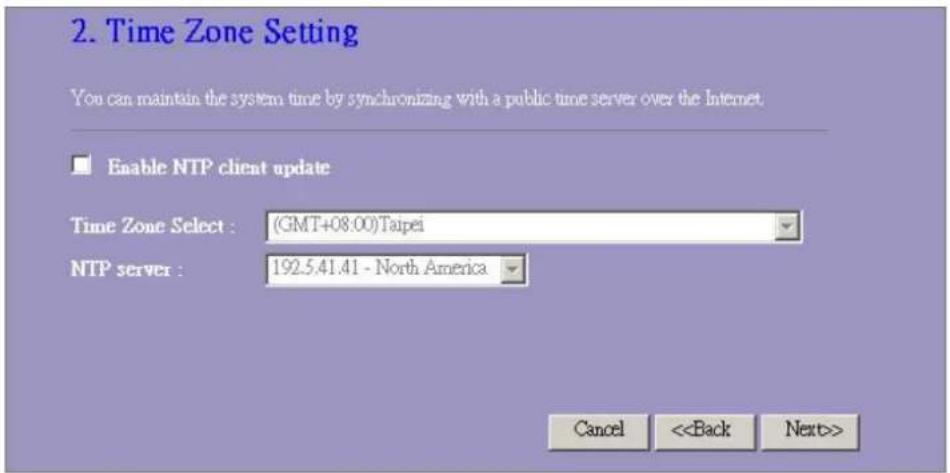
- Mark the check box to enable synchronizing time by NTP server. Select the religion you live and a NTP server by clicking the drop list then click "Next".
text_image
2. Time Zone Setting
You can maintain the system time by synchronizing with a public time server over the Internet.
Enable NTP client update
Time Zone Select : (GMT+08.00)Taipei
NTP server : 192.5.41.41 - North America
Cancel <
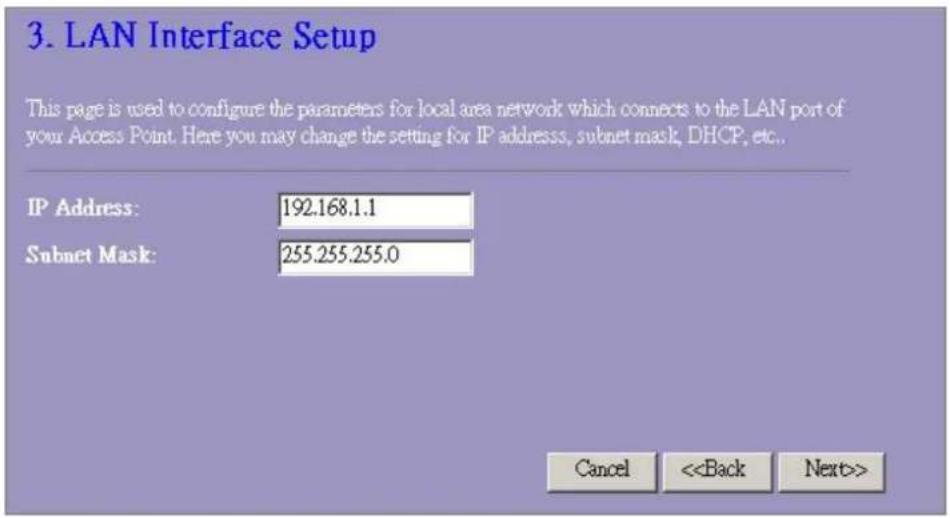
- Specify an IP address and subnet mask for connecting to the router in LAN.
text_image
3. LAN Interface Setup
This page is used to configure the parameters for local area network which connects to the LAN port of your Access Point. Here you may change the setting for IP address, subnet mask, DHCP, etc..
IP Address: 192.168.1.1
Subnet Mask: 255.255.255.0
Cancel <
23414 WLAN ROUT 54-N
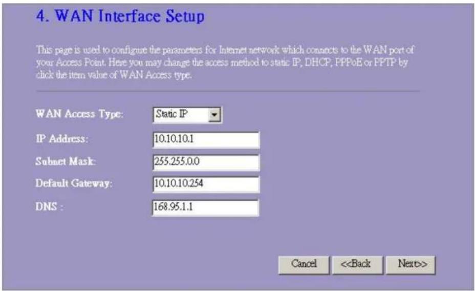
- Select a WAN access type for the router to connect to Internet. Fill in the parameters that required in each blank, and then click the "Next" button. You may get those parameters from your ISP.
text_image
4. WAN Interface Setup
This page is used to configure the parameters for Internet network which connects to the WAN port of your Access Point. Here you may change the access method to static IP, DHCP, PPPoE or PPTP by click the item value of WAN Access type.
WAN Access Type: Static IP
IP Address: 10.10.10.1
Subnet Mask: 255.255.0.0
Default Gateway: 10.10.10.254
DNS : 168.95.1.1
Cancel <
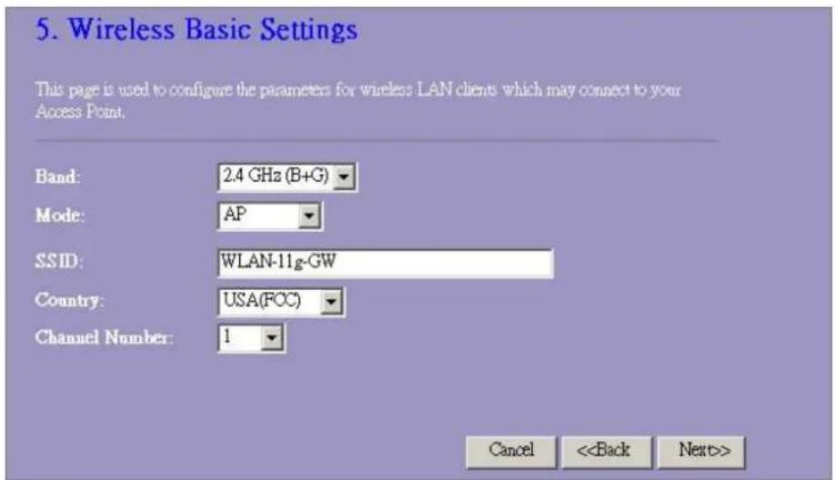
- Select the wireless parameters that are used for associating with this router and click Next.
text_image
5. Wireless Basic Settings
This page is used to configure the parameters for wireless LAN clients which may connect to your Access Point.
Band: 2.4 GHz (B+G)
Mode: AP
SSID: WLAN-11g-GW
Country: USA(FCC)
Channel Number: 1
Cancel <
23414 WLAN ROUT 54-N
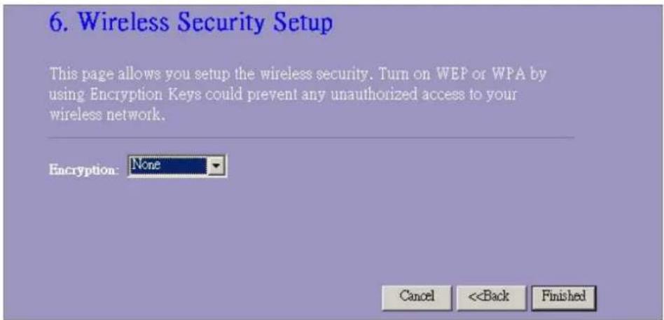
- Click the drop list to select the encryption type for your wireless network. Fill in the parameters for the encryption type you select and click finish to complete configuration.
text_image
6. Wireless Security Setup
This page allows you setup the wireless security. Turn on WEP or WPA by
using Encryption Keys could prevent any unauthorized access to your
wireless network.
Encryption: None
Cancel <
Operation Mode
To select an operation mode for this router, click on the mode that you want to perform and click
the Apply Change button to execute.

text_image
Operation Mode
You can setup different modes to LAN and WLAN interface for NAT and bridging function.
Gateway: In this mode, the device is supposed to connect to internet via ADSL/Cable Modem. The NAT is enabled and PCs in LAN ports share the same IP to ISP through WAN port. The connection type can be setup in WAN page by using PPPOE, DHCP client, PPTP client or static IP.
Bridge: In this mode, all ethernet ports and wireless interface are bridged together and NAT function is disabled. All the WAN related function and firewall are not supported.
Apply Change Reset
23414 WLAN ROUT 54-N
Wireless
Wireless Access Point builds a wireless LAN and can let all PCs equipped with IEEE802.11b/g wireless network adaptor connect to your Intranet. It supports WEP encryption and MAC address filter to enhance the security of your wireless network.
Basic Settings
You can set up the configuration of your Wireless and monitor the Wireless Clients associate with your AP.
Configuration
| Disable Wireless LAN Interface Band | To Disable interface of Wireless LAN |
| To select a band for this device to match 802.11b, 802.11g or both. |
| Mode | Configure this device as AP, WDS or both. |
| SSID | The name of the wireless network |
| Country | Select the region you live. |
| Channel Number | The channel used by the wireless LAN. All devices in the same wireless LAN should use the same channel. |
| Associated Clients | Click "Show Active Clients" button, then an "Active Wireless Client Table" will pop up. You can see the status of all active wireless stations that are connecting to the access point. |
| Enable Universal Repeater Mode | Mark this checkbox to enable Universal Repeater Mode which acts this device as an AP and client simultaneously. |
| SSID of Extended Interface | While you enable the Universal Repeater Mode, you have to specify an SSID for the extended interface. |
Click button at the bottom of the screen to save the above configurations. You can now configure other advance sections or start using the router (with the advance settings in place)
23414 WLAN ROUT 54-N
• Active Wireless Client Table
This is the window that pops up after clicking the "Show Active Clients" button.

text_image
Active Wireless Client Table
This table shows the MAC address, transmission, reception packet counters and encrypted status for each associated wireless client.
MAC Address Tx Packet Rx Packet Tx Rate (Mbps) Power Saving Expired Time (s)
00 e0 4c 81.96.77 32 46 48 n0 300
Refresh Close
| MAC Address | MAC address of this active wireless station. |
| Tx Packet | The number of transmitted packets that are sent out from this active wireless station. |
| Rx Packet | The number of received packets that are received by this active wireless station. |
| TX Rate | The transmission rate |
| Power Saving | Shows if the wireless client is in Power Saving mode |
| Expired Time | This is the time in second before dissociation. If the wireless keeps idle longer than the expired time, this wireless router will dissociate it. The wireless client station has to associate again when it is active. |
| Refresh | Refresh the "Active Wireless Client Table". |
| Close | Close the "Active Wireless Client Table". |
23414 WLAN ROUT 54-N
Advanced Settings
You can set advanced wireless LAN parameters of this router. The parameters include Authentication Type, Fragment Threshold, RTS Threshold, Beacon Interval, Data Rate, Preamble Type, Broadcast SSID, IAPP and 802.11g Protection. We recommend not changing these parameters unless you know what changes will be there on this router.

text_image
Wireless Advanced Settings
These settings are only for more technically advanced users who have a sufficient knowledge about wireless LAN. These settings should not be changed unless you know what effect the changes will have on your Access Point.
Authentication Type: Open System Shared Key Auto
Fragment Threshold: 2346 (256-2348)
RTS Threshold: 2367 (20-2347)
Beacon Interval: 100 (20-1024 ms)
Data Rate: Auto
Preamble Type: Long Preamble Short Preamble
Broadcast SSID: Enabled Disabled
IAPP: Enabled Disabled
102.11g Protection: Enabled Disabled
RP Output Power: 100k 50% 25% 10k 5%
Turbo Mode: Auto Always Off
Apply Changes Reset
Configuration
| Authentication Type | Open System mode | Wireless AP can associate with this wireless router without WEP encryption. |
| Shared Key mode | You should also setup WEP key in the "Security" page and wireless AP associating with this wireless router should use WEP encryption in the authentication phase. |
| Auto | The wireless client can associate with this wireless router by using any one of these two Modes. |
23414 WLAN ROUT 54-N
| Fragment Threshold | To specifies the maximum size of packet during the data transition. The lower values you set, the worst performance it will be. |
| RTS Threshold | If the packet size is smaller the RTS threshold, the wireless router will not send this packet by using the RTS/CTS mechanism. |
| Beacon Interval | The period of time how long a beacon is broadcasted. |
| Data Rate | The "Data Rate" is the data packets limitation this wireless router can transmit. The wireless router will use the highest possible selected transmission rate to transmit the data packets. |
| Preamble Type | It defines the length of CRC block in the frames during the wireless communication. "Short Preamble" is suitable for heavy traffic wireless network. "Long Preamble" provides much communication reliability |
| Broadcast SSID | If you enable "Broadcast SSID", every wireless station located within the coverage of this wireless router can discover this wireless router easily. If you are building a public wireless network, enabling this feature is recommended. Disabling "Broadcast SSID" can provide better security. |
| IAPP | To enables multiple AP to communicate and pass information regarding the location of associated Stations. |
| 802.11g Protection | Some 802.11g wireless adapters support 802.11g protection, which allows the adapters searches for 802.11g singles only. Select the "Disabled" to disable supporting 802.11g protection or select "enable" to support this function. |
| RF Output power | Select the RF (Radio Frequency) power. The RF output power has positive correlation with signal strength. |
| Turbo Mode | Some of our wireless adapters supports turbo mode, which provides a better connection quality. Select "Always" to support turbo mode or select "off" to turn it off. Select "Auto" turns it on or off automatically. |
Click the button at the bottom of the screen to save the above configurations. You can now configure other advance sections or start using the router.
23414 WLAN ROUT 54-N
Security
At the page, you can set up the WEP, WPA Encryption to ensure the security of your Wireless.

text_image
Wireless Security Setup
This page allows you setup the wireless security. Turn on WEP or WPA by using Encryption Keys could prevent any unauthorized access to your wireless network.
Encryption: None Set WEP Key
Use 802.1x Authentication WEP 64bits WEPI 128bits
WPA Authentication Mode: Enterprise (RADIUS) Personal (Pre-Shared Key)
WPA Cipher Suite: TKIP AES
WPA2 Cipher Suite: TKIP AES
Pre-Shared Key Format: Passphrase
Pre-Shared Key:
Enable Pre-Authentication
Authentication RADIUS Server: Port 1812 IP address Password
Note: When encryption WEP is selected, you must set WEP key value.
Apply Changes Reset
23414 WLAN ROUT 54-N
Configuration
| Encryption | To enable WEP, WPA, WPA2 and WPA2 Mixed encryption modes, select the option in the drop list. If you select none, any data will be transmitted without Encryption and any station can access the router. |
| Use 802.1x Authentication | To enable the 802.1x, Click the check box of the item. |
| WPA Authentication Mode | There are two items, “Enterprise (WPA-Radius)” and “Personal (Pre-Shared Key)”. You can select the mode by clicking the item. |
| WPA Cipher Suite | Select the WPA Cipher Suite to be TKIP or AES |
| WPA2 Cipher Suite | Select the WPA2 Cipher Suite to be TKIP or AES |
| Pre-Shared key Format | To decide the format, select what you need in the drop list. |
| Pre-shared Key | Enter the Pre-shared Key according to the pre-shared key format you select. |
| Enable Pre-Authentication | You can mark this checkbox to enable Pre-authentication after selecting Enterprise (RADIUS) WPA 2 authentication mode |
| Authentication RADIUS Sever | If you use RADIUS Sever to ensure your security, you have to set up the parameters in the item. To set up the Port, IP address and Password of your RADIUS, Enter the Port Number, IP and Password. |
Click at the bottom of the screen to save the above configurations. You can now configure other advance sections or start using the router.
23414 WLAN ROUT 54-N
Access Control
To restrict the Number of Access authentication of Stations, Set up the control list in this page.

text_image
Wireless Access Control
If you choose 'Allowed Listed', only those clients whose wireless MAC addresses are in the access control list will be able to connect to your Access Point. When 'Deny Listed' is selected, these wireless clients on the list will not be able to connect the Access Point.
Wireless Access Control Mode: Disable
MAC Address: Comment:
Apply Changes Reset
Current Access Control List:
MAC Address Comment Select
Delete Selected Delete All Reset
Configuration
| Wireless Access Control Mode | Click on the drop list to choose the access control mode. You may select “Allow listed” to allow those allowed MAC addresses or select “Deny Listed” to ban those MAC addresses from accessing to this device. |
| MAC Address & Comment | To set up the Value of MAC Address & Comment; enter the MAC Address and Comment of station and click Apply Changes to save. |
| Current Access Control list | To Delete the station on the list, Click the check box in the select item and click the “Delete Selected”. If you want to delete all stations on the list, click “Delete All” to remove all of them. |
Click button to save the above configurations. You can now configure other advance sections or start using the router.
23414 WLAN ROUT 54-N
WDS Setting

text_image
WDS Settings
Wireless Distribution System uses wireless media to communicate with other APs, like the Ethernet does. To do this, you must set these APs in the same channel and set MAC address of other APs which you want to communicate with in the table and then enable the WDS.
Enable WDS
Add WDS AP: MAC Address
Comment
Apply Changes Reset Set Security Show Statistics
Current WDS AP List:
MAC Address Comment Select
Delete Selected Delete All Reset
Wireless Distribution System allows the router to communicate with other APs wirelessly. To make it work, you must ensure that these APs and the Router are in the same Channel and add these APs MAC Address and Comment values into the WDS list. Don't Forget to Enable the WDS by click the check box of "Enable WDS" and press "Apply Changes" button to save.
To Delete the AP on the list, Click the check box in the select item and click the "Delete Selected". If you want to delete all APs on the list, click "Delete All" to remove all of them.
LAN Interface Setup
To set up the configuration of LAN interface, Private IP of you router LAN Port and Subnet mask for your LAN segment.
LAN Interface Setup
This page is used to configure the parameters for local area network which connects to the LAN port of your Access Point. Here you may change the setting for IP address, subnet mask, DHCP, etc..
IP Address:
Subnet Mask:
DHCP Server:
DHCP Client Range:
802.1d Spanning Tree:

Enable UPnP
Apply Changes
Reset
Configuration
| IP address | The IP of your Router LAN port (Default 192.168.1.1) |
| Subnet Mask | Subnet Mask of you LAN (Default 255.255.255.0) |
| DHCP Server | To give your LAN Client an IP, you have to enable “DHCP Server”. If not, manual setting up your client IP is necessary when you want to use the router as your client's default gateway. |
| DHCP Client Range | Specify the DHCP Client IP address range. You can also click the “Show Client” button to listed those connected DHCP clients. |
| 802.1d Spanning tree | To prevent from network loops and preserve the quality of bridged network |
| Enable UPnP | Mark this checkbox to allow this router to be recognized by UPnP. |
23414 WLAN ROUT 54-N
WAN Interface Setup
This page allows users to configure those parameters for connecting to Internet. You may select the WAN Access Type from the drop list and configure parameters for each mode.
Static IP Mode

text_image
WAN Access Type: Static IP
IP Address: 10.10.10.1
Subnet Mask: 255.255.0.0
Default Gateway: 10.10.10.254
DNS 1: 168.95.1.1
DNS 2:
DNS 3:
Clone MAC Address: 00000000000
| IP Address, Subnet Mask and Default Gateway | Fill in the IP address, Subnet Mask and Default Gateway that provided by your ISP. |
| DNS 1, 2 and 3 | To specify the DNS, and enter the DNS provided by your ISP in DNS 1 2 3. |
DHCP Client Mode

text_image
WAN Access Type: DHCP Client
Attain DNS Automatically
Set DNS Manually
DNS 1: 168.95.1.1
DNS 2:
DNS 3:
Clone MAC Address: 00000000000
| Attain DNS automatically | If your DNS provide by ISP is dynamic, choose “Attain DNS automatically |
| Set DNS Manually | To specify the DNS, and enter the DNS provided by your ISP in DNS 1 2 3. |
23414 WLAN ROUT 54-N
PPPoE Mode

text_image
WAN Access Type: PPPoE
User Name:
Password:
Service Name:
Connection Type: Continuous Connect Disconnect
Idle Time: 5 (1-1000 minutes)
MTU Size: 1452 (1400-1492 bytes)
● Obtain DNS Automatically
○ Set DNS Manually
DNS 1: 168.95.1.1
DNS 2:
DNS 3:
Clone MAC Address: 0000000000
| , password and service name | User Name User Name, password and service name that provided by your ISP. |
| Connection Type | ous” is for Always keep connection“Continu |
| “Connect on demand” is for bill by connection time. You can set up the Idle time for the value specifies the number of time that elapses before the system automatically disconnects the PPPoE session. |
| “Manual” To connect to ISP, click “Connect” manual from the WEB user interface. The WAN connection will not disconnected due to the idle timeout. If the WAN line breaks down and latter links again, the router will not auto-connect to the ISP. |
| Idle Time: | The value specifies the number of idle time that elapses before the system automatically disconnects the PPPoE session. |
| MTU Size | To Enable the Maximum Transmission Unit of Router setup. Any packet over this number will be chopped up into suitable size before sending. Larger number will enhance the transmission performance.Enter your MTU number in the text-box to set the limitation. |
| Attain DNS automatically: | If your DNS provide by ISP is dynamic, choose “Attain DNS automatically |
| Set DNS Manually | To specify the DNS, and enter the DNS provided by your ISP in DNS 1 2 3. |
23414 WLAN ROUT 54-N
PPTP Mode

text_image
WAN Access Type: PPTP
IP Address: 172.16.1.2
Subnet Mask: 255.255.255.0
Server IP Address: 172.16.1.1
User Name: admin
Password: **********
MTU Size: 1452 (1400-1492 bytes)
Attain DNS Automatically
Set DNS Manually
DNS 1: 168.95.1.1
DNS 2:
DNS 3:
| IP Address, Subnet Mask, Server IP Address, User Name and Password | Fill in the IP address, Subnet Mask, Server IP Address, User Name and password that provided by your ISP. |
| MTU Size | To Enable the Maximum Transmission Unit of Router setup. Any packet over this number will be chopped up into suitable size before sending. Larger number will enhance the transmission performance.Enter your MTU number in the text-box to set the limitation. |
| Attain DNS automatically | If your DNS provide by ISP is dynamic, choose “Attain DNS automatically |
| Set DNS Manually | To specify the DNS, and enter the DNS provided by your ISP in DNS 1 2 3. |
23414 WLAN ROUT 54-N
Common configurations for WAN interface
There are some settings are able to be configured on each WAN access types:

text_image
Clone MAC Address: 00000000000
Enable Web Server Access on WAN from port : 8080
Enable IPsec pass through on VPN connection
Enable PPTP pass through on VPN connection
Enable L2TP pass through on VPN connection
Apply Changes Reset
| Enable Web Server Access on WAN from port | To Enable the user to access this Router through Internet, Enter the specific IP and the port number |
| Enable IPsec pass through on VPN connection | Mark the check box to enable IPsec pass through on VPN connection and clear the checkbox to disable. |
| Enable PPTP pass through on VPN connection | Mark the check box to enable PPTP pass through on VPN connection and clear the checkbox to disable. |
| Enable L2TP pass through on VPN connection | Mark the check box to enable L2TP pass through on VPN connection and clear the checkbox to disable. |
| Clone MAC Address | When ISP use MAC address authentication (with DHCP), then the MAC address of the Ethernet card attached to your Cable modem must be registered with the ISP before connecting to the WAN (Internet). If the Ethernet card is changed, the new MAC address must be registered with the ISP.MAC cloning feature allows the MAC address reported by WAN side network interface card to be set to the MAC address already registered with the ISP eliminating the need to register the new MAC address with the ISP. This feature does not change the actual MAC address on the NIC, but instead changes the MAC address reported by Wireless Router to client requests. To Change the MAC address, enter it in the text box. |
Port Filtering
The firewall could not only obstruct outside intruders from intruding your system, but also restricting the LAN users.
Port Filtering To restrict certain type of data packets from your LAN to Internet through the Router, add them on the Current Filtering Table.

text_image
Port Filtering
Entries in this table are used to restrict certain types of data packs from your local network to Internet through the Gateway. Use of such filters can be helpful in securing or restricting your local network.
Enable Port Filtering
Local Port Range:
Protocol: Both
Comment:
Apply Changes Reset
Current Filter Table:
Local Port Range Protocol Comment Select
Delete Selected Delete All Reset
Configuration
| STEPS | 1. Click the check box of “Enable Port Filtering” to enable the function. |
| 2. Enter the Port range (EX 25-110), Protocol (UDP/TCP), and comment (EX. E-Mail) |
| 3. To Delete the Port range on the list, Click the check box in the select item and click the “Delete Selected”. If you want to delete all entries on the list, click “Delete All” to remove all of them. |
Click at the bottom of the screen to save the above configurations. You can now configure other advance sections or start using the router.
23414 WLAN ROUT 54-N
IP filtering
The Wireless Router could filter the outgoing packets for security or management consideration. You can set up the filter against the IP addresses to block specific internal users from accessing the Internet.

text_image
IP Filtering
Entries in this table are used to restrict certain types of data packets from your local network to Internet through the Gateway. Use of such filters can be helpful in securing or restricting your local network.
Enable IP Filtering
Local IP Address:
Protocol: Both Comment:
Apply Changes Reset
Current Filter Table:
Local IP Address Protocol Comment Select
DeleteSelect Delete A1 Reset
Configuration
| STEPS | 1. Click the check box of “Enable IP Filtering” to enable the function. |
| 2. Enter the specific Local IP address (EX 10.10.3.9), Protocol (UDP/TCP), and comment (EX. Peter) |
| 3. To Delete the IP address on the list, Click the check box in the select item and click the “Delete Selected”. If you want to delete all entries on the list, click “Delete All” to remove all of them. |
Click at the bottom of the screen to save the above configurations. You can now configure other advance sections or start using the router.
23414 WLAN ROUT 54-N
MAC filtering
The Wireless Router could filter the outgoing packets for security or management consideration. You can set up the filter against the MAC addresses to block specific internal users from accessing the Internet.

text_image
MAC Filtering
Entries in this table are used to restrict certain types of data packets from your local network to Internet through the Gateway. Use of such filters can be helpful in securing or restricting your local network.
Enable MAC Filtering
Local MAC Address:
Comment:
Apply Changes Reset
Current Filter Table:
Local MAC Address Comment Select
Delete Selected Delete All Reset
Configuration
| STEPS | 1. Click the check box of “Enable MAC Filtering” to enable the function. |
| 2. Enter the specific MAC address (EX 00:0e:b6:a8:72), and comment (EX. Peter) |
| 3. To Delete the MAC address on the list, Click the check box in the select item and click the “Delete Selected”. If you want to delete all Entries on the list, click “Delete All” to remove all of them. |
Click at the bottom of the screen to save the above configurations. You can now configure other advance sections or start using the router.
23414 WLAN ROUT 54-N
Port forwarding
The Port Forwarding allows you to re-direct a particular range of service port numbers (from the Internet/WAN Ports) to a particular
LAN IP address. It helps you to host some servers behind the router NAT firewall.

text_image
Port Forwarding
Entries in this table allow you to automatically reduce common network services to a specific machine behind the NAT firewall. These settings are only necessary if you wish to host some sort of server like a web server or mail server on the private local network behind your Gateway's NAT firewall.
Enable Port Forwarding
Local IP Address: Protocol: Both Port Range:
Comment:
Apply Changes Reset
Current Port Forwarding Table:
Local IP Address Protocol Port Range Comment Select
Delete Selected Delete All Reset
Configuration
STEPS
1. Click the check box of "Enable port forwarding" to enable the function.
2. Enter the specific IP address (EX 10.10.10.10), Protocol (UDP/TCP), Port range (EX 25-110), and comment (EX. E-Mail)
3. To Delete the IP address on the table, Click the check box in the select item and click the "Delete Selected". If you want to delete all Entries on the table, click "Delete All" to remove all of them.
Click at the bottom of the screen to save the above configurations.
23414 WLAN ROUT 54-N
URL Filtering
The URL Filter allows users to prevent certain URL from accessing by users in LAN. This filter will block those URLs that contain certain keywords.

text_image
URL Filtering
URL filter is used to deny LAN users from accessing the internet. Block those URLs which contain keywords listed below.
(EX: google; www.google.com or 72.14.203.99)
Enable URL Filtering
URL Address:
Apply Changes Reset
Current Filter Table:
URL Address Select
Delete Selected Delete All Reset
Configuration
STEPS
1. Click the check box of "Enable URL Filtering" to enable the function.
2. Enter the URL that is going to be banned.
3. To Delete the URL on the table, Click the check box in the select item and click the "Delete Selected". If you want to delete all URLs on the table, click "Delete All" to remove all of them.
Click at the bottom of the screen to save the above configurations.
23414 WLAN ROUT 54-N
Virtual DMZ
The virtual DMZ is used to enable protocols, which need to open ports on the router. The router will forward all unspecified incoming traffic to the host specified in this page.

text_image
Virtual DMZ
A Demilitarized Zone is used to provide Internet services without sacrificing unauthorized access to its local private network. Typically, the virtual DMZ host contains devices accessible to Internet traffic, such as Web (HTTP) servers, FTP servers, SMTP (e-mail) servers and DNS servers.
Enable Virtual DMZ
Virtual DMZ Host IP Address:
Apply Changes Reset
To configure it, enter the Host IP (private IP address) and Click "Apply changes" to enact the setting.
Status
In the home page of the Wireless Router, the left navigation bar shows the options to configure the system. In the right navigation screen is the summary of system status for viewing the configurations.
Status
This page shows the current status and some basic settings of the device.
SYSTEM
| Uptime | 0day:0h:2m:54s |
| Firmware Version | v1.0 |
| Wireless Configuration |
| Mode | AP |
| Band | 2.4 GHz (B+G) |
| SSID | WLAN-11g-GW |
| Channel Number | 11 |
| Encryption | Disabled |
| BSSID | 00:e0:7d:c0:c7:d1 |
| Associated Clients | 0 |
LAN Configuration
| IP Address | 192.168.1.1 |
| Subnet Mask | 255.255.255.0 |
| DHCP Server | Enabled |
| MAC Address | 00:e0:7d:c0:c7:d1 |
WAN Configuration
| Attain IP Protocol | Static IP |
| IP Address | 10.10.10.1 |
| Subnet Mask | 255.255.0.0 |
| Default Gateway | 10.10.10.254 |
| MAC Address | 00:e0:7d:c0:c7:d3 |
23414 WLAN ROUT 54-N
- System
| Uptime | The period that you power the device on. |
| Firmware Version | The version of the firmware applied on this device. |
● Wireless Configuration
| Mode | The operation mode of the wireless router |
| Band | The performing band of this wireless router |
| SSID | The name of this wireless network |
| Channel Number | The channel used by the wireless LAN. All devices in the same wireless LAN should user the same channel |
| Encryption | The security encryption status of this wireless network |
| BSSID | The Basic Service Set Identity of this router.(This parameter is the same as the MAC address of LAN port) |
| Associated Clients | The number of associated clients. |
• LAN Configuration
| IP Address | IP Address of router |
| Subnet Mask | Subnet Mask of the router |
| DHCP Server | Enabled or Disable of DHCP |
| MAC Address | MAC Address of LAN-port |
- WAN Configuration
| Attain IP Protocol | Static IP address |
| IP Address | IP address of WAN-port |
| Subnet Mask | Subnet Mask of WAN-port |
| Default Gateway | Default Gateway of WAN-port |
| MAC Address | MAC Address of WAN-port |
23414 WLAN ROUT 54-N
Statistics
On this page, you can monitor the sent & received packets counters of wireless, Ethernet LAN, and Ethernet WAN. To see the latest report, click refresh button.
Statistics
This page shows the packet counters for transmission and reception regarding to wireless and Ethernet networks.
| Wireless LAN | Sent Packets | 145357 |
| Received Packets | 1121 |
| Ethernet LAN | Sent Packets | 6845 |
| Received Packets | 858102 |
| Ethernet WAN | Sent Packets | 8285 |
| Received Packets | 0 |
Refresh
DDNS
This page allows users to connect to DDNS. To enable DDNS, Mark the "Enable DDNS" checkbox. Select the service provider from the drop list. Fill in domain name, username, and password. Click the "Apply Change" button after configuration.

text_image
Dynamic DNS Setting
Dynamic DNS is a service, that provides you with a valid, unchanging, internet domain name (an URL) to go with that (possibly ever-changing) IP address.
Enable DDNS
Service DynDNS
Provider:
Domain Name: testdynalsc.org
User:
Name/Email:
Password/Key:
Note:
For TEO, you can have a 30 days free trial here or manage your TEO account in control panel.
For DynDNS, you can create your DynDNS account here.
Apply Change Reset
23414 WLAN ROUT 54-N
Time Zone Setting
This page allows users to configure the time of the router. To specify manually, fill in the blanks in "Current Time" and click the "Apply Change" button. To synchronize time from a timeserver, please mark the "Enable NTP client update" checkbox, select a NTP server from the drop list or manually enter a NTP server. Click the "Apply Change" button after your configuration.

text_image
Time Zone Setting
You can maintain the system time by synchronizing with a public time server
over the Internet.
Current Time : Yr 2000 Mon 1 Day 3 Ht 8 Mn 38 Sec 11
Time Zone
Select : GMT+08.00Taipei
Enable NTP client update
NTP server : 192.541.41 - North America
(Manual IP Setting)
Apply Change Reset Refresh
m Log Syste
This System Log page shows the information of the current activities on the router. To enable system log function:
1. Mark the "Enable Log" c checkbox.
2. To see all information of the system, select the "system all" checkbox.
To see wireless information only, select the "wireless" checkbox. To sent the log information to a certain note, select the "Enable Remote Log" checkbox and fill in the IP address in the "Log Server IP Address" box.
3. Click the "Apply Changes" button to activate
You could also click the "Refresh" button to refresh the log information or click the "clear" button to clean the log table.
23414 WLAN ROUT 54-N

text_image
System Log
This page can be used to use remote log server and show the system log.
Enable Log
system all
wireless
Enable Remote Log
Log Server IP Address:
Server Port. 514
Apply Changes
Refresh
Clear
Upgrade Firmware
To Upgrade Firmware,
| STEPS | 1. Click “browse...” button to select the firmware you want to upgrade. |
| 2. Click Upload to start the upgrade process.Please don’t close the WEB-browser and wait for process to complete. When Upgrade is completed, you can start to use the router. |

text_image
Upgrade Firmware
This page allows you upgrade the Access Point firmware to new version. Please note, do not power off the device during the upload because it may crash the system.
Select File:
Browse...
Upload Reset
23414 WLAN ROUT 54-N
Save and Reload Settings
To save setting to file, click "Save..." button.
To load setting from file,
1. Click "Browse..." on the to select the file
2. Click upload to start the process and wait for it to complete
To reset setting to Default, click reset to start the process and it will be completed till the status LED start blinking.
Save/Reload Settings
This page allows you save current settings to a file or reload the settings from the file which was saved previously. Besides, you could reset the current configuration to factory default.
Save Settings to File:
Save...
Load Settings from File:

Reset Settings to Default:
Reset
Password
To set up the Administrator Account information, enter the Username, New password, and reenter the password on the text box. Don't forget to click the "Apply Changes" to save the configuration.

text_image
Password Setup
This page is used to set the account to access the web server of Access Point.
Empty user name and password will disable the protection.
User Name:
New Password:
Confirmed
Password:
Apply Changes Reset
23414 WLAN ROUT 54-N
PRODUCT SPECIFICATIONS
| Standard | IEEE802.3, 10BASE-TIEEE802.3u, 100BASE-TXIEEE802.3x full duplex operation and flow controlIEEE802.11b wireless LAN infrastructureIEEE802.11g wireless LAN infrastructure |
| Interface | 1 * WAN port4 * 10/100 RJ-45 Fast Ethernet switching portsAntenna: 802.11b/g wireless reverse SMA detachable |
| WAN Connection | Ethernet 10/100 Mbps |
| Cable Connections | RJ-45 (10BASE-T): Category 3,4,5 UTPRJ-45 (100BASE-TX): Category 5 UTP |
| Network Data Rate | 802.11b: 1, 2, 5.5 and 11Mbps802.11g: 6, 9, 12, 18, 24, 36, 48, and 54Mbps |
| Transmission Mode | Auto-Negotiation (Full-duplex, Half-duplex) |
| LED indications | System: Power, StatusPort (WAN): ACT/LINKPort (LAN): ACT/LINKPort (Wireless): ACT |
| Security | 64/128-bit WEP,WPA (TKIP with IEEE 802.1x), WPA2, AES |
| Receiver Sensitivity | 54Mbps OFDM, 10%PER, -71dBm11Mbps CCK, 10%PER, -81dBm1Mbps BPSK, 10%PER, -92dBm |
| Memory | Flash: 2MB NOR type, SDRAM: 8MB |
| Transmit Power | 16dBm~18dBm |
| Range Coverage | Indoor 35~100 metersOutdoor 100~300meters. |
| Emission | FCC CLASS B, CE, VCCI Class B |
| Operating Temperature | 0^ 40^ ( 32^ 104^ ) |
| Operating Humidity | 10% - 90% |
| Power Supply | External Power Adapter, 12VDC/ 1A |
23414 WLAN ROUT 54-N
D
CE Markierungswarnung
CE
Dieses Gerät entspricht den Bedingungen bezüglich elektromagnetischer Kompatibilität, EN55022 Klasse B für ITE, dem erforderlichen Schutzbedarf der Richtlinie 89/336/EEC in Annäherung an die Gesetze der Mitgliedsstaaten in Zusammenhang mit elektromagnetischer Kompatibilität.
Das Unternehmen erneuert seine Produkte laufend und es kann sein, dass Informationen in diesem Dokument nicht aktuell sind. Bitte kontaktieren Sie Ihren örtlichen Händler für die neuesten Informationen. Kein Teil dieses Dokumentes darf in irgendeiner Form kopiert oder reproduziert werden ohne schriftliches Einverständnis des Unternehmens.
Warenzeichen:
Alle Handelsnamen und Warenzeichen sind das Eigentum der jeweiligen Unternehmen. Copyright © 2007, All Rights Reserved.
23414 WLAN ROUT 54-N
Vielen Dank, dass Sie sich für dieses Produkt entschieden haben. Bevor Sie beginnen, sollten Sie den Inhalt der Packung überprüfen.
Die Packung sollte folgende Teile enthalten:
1. Einen Wireless Router
2. Ein Spannungsadapter
3. Eine Bedienungsanleitung (CD)
4. Eine abnehmbare Antenne
EINLEITUNG ZUM WIRELESS ROUTER
Allgemeine Beschreibung
Der Wireless Router mit eingebautem 4-Port 10/100 Mbps Fast Ethernet Switch ist die neueste Generation von Wireless Router Produkten für Home/Office und SOHO Benutzer. Dieser funktionsreiche und eigenständige kompakte Wireless Router ist vollständig einsatzbereit für Breitband Zugriff in LAN und wireless Umgebung. Dieses Gerät wurde speziell hergestellt, um LAN und wireless Benutzern die kosteneffektivste Methode mit Mehrfachzugriff auf das Internet zu den Kosten einer einzigen öffentlichen IP Adresse zu bieten, IP Sharing, und in den Genuss der Plug-und-Play Installation zu kommen. Außerdem ermöglicht der eingebaute 4-Port 10/100Mbps Switch es dem Nutzer, das Netzwerkkabel in das Gerät zu stecken, ohne einen zusätzlichen Switch kaufen zu müssen.
Dieses Gerät ist auch ein wireless Access Point. Benutzer können sich über wireless Netzwerkadapter überall im Bereich der Funkübertragung mit dem Internet verbinden Es ist ideal für SOHO Benutzer, die ständigen und bequemen Zugriff auf das Internet benötigen ohne die Einschränkung von Verbindungskabeln.
Die freundliche Web-basierte graphische Schnittstelle für das Setup ermöglicht jedem unerfahrenen Benutzer den schnellen Einstieg in die Plug-und-Play Bedienung. Eingebaute DHCP Server vereinfachte IP Adressverwaltung und keine MIS Personen für täglichen technischen Service benötigt. Dazu ist auch NAT/Firewall bei dieser kompakten Routerbox inbegriffen, um das ganze LAN vor Angriffen von außen zu beschützen.
23414 WLAN ROUT 54-N
Hauptmerkmale
Der Switch bietet die folgenden Funktionen:
■ Entspricht dem IEEE 802.11b/g Wirelessstandards
■ Bietet eine abnehmbare 802.11b/g Reverse SMA Antenne
■ Hochgeschwindigkeitsdatentransfer bis zu 54 Mbps
■ Unterstützt Turbomodus für 72 Mbps Datentransfer
■ Unterstützt wireless Datenverschlüsselung mit 64/128-bit WEP, WPA (TKIP mit IEEE 802.1x), WPA2 und AES Funktionen
■ Unterstützt System Log
■ Unterstützt Authentifizierung für wireless Connectivity basierend auf ESSID
■ Bietet MAC Zugriffskontrolle und versteckte SSID Funktion
■ WDS unterstützt mit WEP, TKIP und AES Verschlüsselung
■ Kanal: USA 11, Europa 13, Japan 14
■ Unterstützt NAT/NAPT IP Sharing
■ Unterstützt Statische IP, PPPoE, PPTP & DHCP Client
■ SPI Anti-DoS Firewall; Virtuelle DMZ; DNS Relay, UPnP
■ Bietet DHCP Server
■ Unterstützt ALG für FTP, NetMeeting, DDNS (DynDNS, TZO)
■ Unterstützt Firmware Upgradefunktion über das Web
■ Konform mit FCC Teil 15.247 für US, ETS 300 328 für Europa
■ Flash: 2MB NOR Typ, SDRAM: 8MB
■ Zertifizierungen: FCC Klasse B, CE Zeichen, VCCI Klasse B
23414 WLAN ROUT 54-N
Die Frontseite

natural_image
Illustration of a device casing with a black cover and 'vivanco' logo, no readable text or symbols beyond the brand name.
LED Beschreibung
System LEDs
System LED Anzeigen sind an der Vorderseite angebracht, um den Funktionsstatus des gesamten Gerätes anzuzeigen.
\- PWR (Power) LED
Diese Anzeige leuchtet grün, wenn der Wireless Router Spannung empfängt, andernfalls ist sie nicht an.
\- STATUS LED
The LED wird für einige Sekunden dunkel sein, wenn das System gestartet wird. Danach wird die LED periodisch blinken, um zu zeigen, dass der Wireless Router normal arbeitet. Falls die LED grün / dunkel bleibt, bedeutet dies, dass ein Fehler im System unterlaufen ist. Sie müssen Ihren Händler kontaktieren oder versuchen, das System neuzustarten.
Port LEDs (Wireless)
\- WLAN LED
I. Wenn das System bereit für Datenübertragung und Empfang ist, ist es ständig grün.
23414 WLAN ROUT 54-N
II. Wenn Daten übertragen oder empfangen werden, blinkt es grün.
Port LEDs (WAN)
Port LED Anzeigen sind an der Vorderseite angebracht, um den Funktionsstatus vom WAN Port anzuzeigen.
\- Act/Link LED
Die LED bleibt leuchtend (grün). Das bedeutet, dass der Port eine gute Verbindung zu den angeschlossenen Geräten hat.
Die LED wird grün blinken, wenn Datenverkehr über den Port geht.
Port LEDs (LAN)
Port LEDs (LAN) Anzeigen auf der Frontseite zeigen den Funktionsstatus der 10/100 Mbps Fast Ethernet Switching Ports an.
\- Act/Link LED
Jeder Port hat eine Act/Link LED. Ständig grün (Verbindungsstatus) zeigt an, dass der Port eine gute Verbindung zu den angeschlossenen Geräten hat. Blinkend grün zeigt an, dass der Port Daten empfängt oder zwischen den angeschlossenen Geräten überträgt.
Die Rückseite

text_image
DC 12V LAN4 LAN3 LAN2 LAN1 WAN Restore Default
Spannungsanschluss
Stecken Sie das kreisförmige Ende des Spannungsadapters fest in die Rückseite des Wireless Routers und das andere Ende in eine Steckdose. Nun ist das System bereit.
Platzierung (optional)
Es gibt drei Möglichkeiten, den Router zu platzieren. Die erste Möglichkeit ist, den Router horizontal auf einer Oberfläche zu platzieren. Die zweite Möglichkeit ist, den Router an der Wand zu befestigen. Die dritte Möglichkeit ist, den Router vertikal auf einer Oberfläche zu platzieren. Diese Optionen werden unten detaillierter erklärt.
23414 WLAN ROUT 54-N
Tisch Option
1. Der Router hat einen Plastikständer, der in zwei Teile geteilt werden kann.
2. Verbinden Sie einen Teil des Ständers mit der Seite des Routers.
3. Verfahren Sie genauso mit dem zweiten Teil.
4. Platzieren Sie den Router.
Wandbefestigungsoption
Bevor Sie den Router an der Wand befestigen, müssen Sie die Schritte der Tischoption zuerst ausführen.
1. Wählen Sie eine Stelle mit Zugriff auf Kabel und Steckdose.
2. Ziehen Sie die Einheit heraus. Stellen Sie es mit der Oberseite nach unten auf eine flache Oberfläche und markieren Sie die zwei Löcher für die Anker.
3. Bringen Sie die Wandbefestigungsanker (Plastik) mit Werkzeugen wie Bohrer oder Hammer in der Wand an.
4. Fügen Sie die mitgelieferten Schrauben in jedes Loch der Ständerteile ein.
5. Befestigen Sie die Einheit an den Ankern in der Wand.
Ständeroption
1. Deratutereb Ständerteile.
2. Verbinden Sie die beiden Teile zu einem Ständer. Verbinden Sie ihn mit der Seite des Routers in der Nähe des Spannungsports. Drücken Sie den Ständer hoch, damit er einschnappt.
3. Platzieren Sie den Router.
23414 WLAN ROUT 54-N
Werkseinstellung Wiederherstelltaste
1. Drücken Sie die Taste länger als 5 Sekunden und lassen Sie ihn dann los. Das System wird auf die Standard Werkseinstellungen zurückgestellt. In der Zwischenzeit schreibt das System den Flash auf den Standardwert und die Status LED stoppt für einen Moment. Ungefähr 60 Sekunden später blinkt die Status LED periodisch grün. Nun sind alle Systemparameter auf die Standard Werkseinstellung zurückgesetzt worden. Falls der Vorgang durch irgendeinen Grund (keine Spannung, ...) unterbrochen worden ist, wird es einen Systemfehler geben. Bevor Sie den Vorgang ausführen, stellen Sie bitte eine sichere Betriebsumgebung sicher.
2. Um den Router neu zu starten, drücken Sie die Taste für 2 - 5 Sekunden und lassen sie dann los. Die Einstellungen werden nicht gelöscht. Warten Sie darauf, dass der Router den Neustart abgeschlossen hat. Dann können Sie mit der Benutzung anfangen.
Achtung : Unvollständige Vorgänge zur Wiederherstellung der Werkseinstellung verursachen, dass der Wireless Router nicht richtig funktioniert. Sollten Sie unglücklicherweise in dieser Situation sein, versuchen Sie nicht, ihn selber zu reparieren. Bitten Sie Ihren lokalen Händler um Hilfe.
23414 WLAN ROUT 54-N
DEN WIRELESS ROUTER INSTALLIEREN UND BENUTZEN
Dieses Kapitel bietet eine schrittweise Anleitung für die Installation und Konfiguration des Wireless Routers. Wir schlagen vor, dass Sie das ganze Kapitel durcharbeiten und dann mit der fortgeschritteneren Bedienung weiter machen.
Netzwerkkonfiguration Setup
Schritte, um das Netzwerk aufzubauen:
Verbinden Sie das ADSL oder Kabelmodem mit dem Ethernet WAN Port auf der Rückseite des Wireless Routers. Benutzen Sie dafür das UTP Kabel.
➢ Verbinden Sie die Telefonleitung von der Wandbuchse mit dem Eingangsport des ADSL Modems, oder das Koaxialkabel mit dem Eingangsport des Kabelmodems..
Stecken Sie den Poweradapter in das Modem und schalten Sie es an. Installieren Sie die Ethernetkarte in Ihren Rechner. Beziehen Sie sich dabei auf die Bedienungsanleitung, die mit der Karte geliefert wurde.
➢ Verbinden Sie den Rechner mit dem Wireless Router, indem Sie Standard Twisted-Pair Ethernet Kabel von der Ethernet Karte des Rechners zu einem 10/100 Mbps Ethernet Port auf der Rückseite des Wireless Routers benutzen.
Stecken Sie den Power Adapter in den Router und das andere Ende in die Steckdose.
23414 WLAN ROUT 54-N
Computerkonfiguration Setup
Um mit diesem Wireless Router zu kommunizieren, müssen Sie die IP Adressen Ihres Rechners so konfigurieren, dass sie mit dem Gerät kompatibel sind. Der Router unterstützt DHCP Server. Dies ist standardmäßig aktiviert. Benutzer, die ihre IP Adresse mit "Automatisch eine IP Adresse erhalten" konfigurieren, können die folgende Anleitung zur IP Konfiguration überspringen.
Anmerkung:
1. Die Standard Netzwerkeinstellungen des Gerätes:
IP Adresse: 192.168.1.1
Subnetzmaske: 255.255.255.0
DHCP Server: aktiviert
2. In der folgenden TCP/IP Konfigurationsanleitung wird die IP Adresse "192.168.1.2" als Ihre IP Adresse vorausgesetzt, falls Sie IP Adressen manuell spezifizieren wollen. Bitte wählen Sie NICHT 192.168.1.1 als IP Adresse. 192.168.1.1 wurde als Standard-IP für dieses Gerät eingestellt.
3. Die folgende TCP/IP Konfigurationsanleitung setzt Windows XP als Betriebssystem voraus.
Vorgänge, um IP Adressen für Ihren Rechner zu konfigurieren
1. Falls Sie in der klassischen Startmenü Ansicht sind, klicken Sie auf Start > Einstellungen > Systemsteuerung > Netzwerkverbindungen.
Falls Sie in der Startmenü Ansicht sind, klicken Sie auf Start (Systemsteuerung (Netzwerkverbindungen.
2. Doppelklicken Sie auf "Lokale Umgebungsverbindungen"

text_image
Network Connections
File Edit View Favorites Tools Advanced Jobs
Back Search Search Updates
Network Connections
Network Tools
Create a new connection
Stop up a network user of the network
Modify the network device
Prepare this connection
Remove this connection
New installed of the connection
Change settings of the connection
Other Features
Connect/Forward
PC Network Access
PC Descriptive
PC Connection
Details
Local Server Connections
Link to High-Speed Internet
Enabled
500-800-Based PCI Fast Ethernet Adapter
Link Address: 100, 200, 300, 400, 500, 600, 700, 800, 900, 1000, 1100, 1200, 1300, 1400, 1500, 1600, 1700, 1800, 1900, 2000, 2100, 2200, 2300, 2400, 2500, 2600, 2700, 2800, 2900, 3000, 3100, 3200, 3300, 3400, 3500, 3600, 3700, 3800, 3900, 4000, 4100, 4200, 4300, 4400, 4500, 4600, 4700, 4800, 4900, 5000, 5100, 5200, 5300, 5400, 5500, 5600, 5700, 5800, 5900, 6000, 6100, 6200, 6300, 6400, 6500, 6600, 6700, 6800, 6900, 7000, 7100, 7200, 7300, 7400, 7500, 7600, 7700, 7800, 7900, 8000, 8100, 8200, 8300, 8400, 8500, 8600, 8700, 8800, 8900, 9000, 9100, 9200, 9300, 9400, 9500, 9600, 9700, 9800, 9900, 1.1.1.1.1.1.1.1.1.1.1.1.1.1.1.1.1.1.1.1.1.1.1.1.1.1.1.1.1.1.1.1.1.1.1.1.1.1.1.1.1.1.1.1.1.1.1.1.1.1.1
23414 WLAN ROUT 54-N
3. Klicken Sie auf Internet Protokoll (TCP/IP) und dann auf Eigenschaften.

text_image
Local Area Connection Properties
General Authentication Advanced
Connect using:
SiS 900-Based PCI Fast Ethernet Adapter
Configure...
This connection uses the following items:
Client for Microsoft Networks
File and Printer Sharing for Microsoft Networks
QoS Packet Scheduler
Internet Protocol (TCP/IP)
Install... Uninstall Properties
Description
Allows your computer to access resources on a Microsoft
network.
Show icon in notification area when connected.
OK Cancel
4. Sie können "Automatisch eine IP Adresse erhalten" wählen (empfohlen), um eine IP Adresse automatisch zu erhalten. Oder Sie wählen "Die folgende IP Adresse benutzen", um IP Adressen manuell zu spezifizieren. Bitte klicken Sie nach der Konfiguration auf die Taste OK.

text_image
Internet Protocol (TCP/IP) Properties
General
You can get IP settings assigned automatically if your network supports
this capability. Otherwise, you need to ask your network administrator for
the appropriate IP settings.
Obtain an IP address automatically
Use the following IP address:
IP address: 132, 168, 1, 2
Subnet mask: 255, 255, 255, 0
Default gateway 132, 168, 1, 254
Obtain DNS server address automatically
Use the following DNS server addresses:
Preferred DNS server: . . . .
Alternate DNS server: . . . .
Advanced...
OK Cancel
VERWALTUNG
Wireless Router Konfigurationssetup
Damit das ganze Netzwerk erfolgreich arbeitet, ist es notwendig, den Wireless Router mit Ihrem Rechner mit einem installierten Webbrowser zu konfigurieren. Bitte befolgen Sie die unten aufgeführten Schritte.
1. Klicken Sie doppelt auf die Internet Webbrowser Ikone auf Ihrem Desktop-Bildschirm (Netscape Communicator 4.0 und Internet Explorer 3.0 oder höhere Version).
2. Geben Sie 192.168.1.1 in die URL Webadresszeile ein und drücken Sie Enter.

text_image
about:blank - Microsoft Internet Explorer
File Edit View Favorites Tools Help
Back History
Address http://192.168.1.1 Go Links »
3. Das Feld Benutzername und Passwort erscheint.
- Geben Sie admin an die Stelle Benutzername ein (Standardwert).
- Geben Sie admin an die Stelle Passwort ein (Standardwert).
- Klicken Sie auf OK.

text_image
Enter Network Password
Please type your user name and password.
Site: 192.168.1.1
Realm 802.11g Wireless Broadband Router
User Name admin
Password ******
Save this password in your password list
OK Cancel
23414 WLAN ROUT 54-N
4. Die Graphische Benutzerschnittstelle
Nach der Passwortauthorisierung zeigt sich der Setup Assistent als Homepage der Graphischen Benutzerschnittstelle. Sie können auf jeden Ordner auf der linken Seite jeder Seite klicken, um Zugriff auf jede Konfigurationsseite zu bekommen.

text_image
802.11g Wireless Broadband Router
Setup Wizard
The setup wizard will guide you to configure access point for next time. Please follow the setup wizard.
stop by stop
Welcome to Setup Wizard
The Wizard will guide you the through following steps. Begin by clicking on Next.
1. Setup Operating Mode
2. Choose Your Email Cost
3. Setup LAN Interface
4. Setup WAN Interface
5. Wireless LAN Setting
6. Wireless Security Setting
Next>
23414 WLAN ROUT 54-N
Installationsassistent
Falls Sie den Router zum ersten Mal benutzen, können Sie die folgenden Vorgänge des Installationsassistenten befolgen, um eine schrittweise Konfiguration durchzuführen.
Anmerkung: Die folgende Anleitung führt eine allumfassende Einleitung zum Installationsassistenten durch. Detaillierte Informationen zu jedem Thema finden Sie in der Einleitung jeder Seite.
1. Um den Installationsassistenten zu starten, klicken Sie bitte auf die Taste "Weiter" zum Fortfahren.

text_image
Setup Wizard
The setup wizard will guide you to configure access point for first time. Please follow the setup wizard step by step.
Welcome to Setup Wizard.
The Wizard will guide you the through following steps. Begin by clicking on Next.
1. Setup Operation Mode
2. Choose your Time Zone
3. Setup LAN Interface
4. Setup WAN Interface
5. Wireless LAN Setting
6. Wireless Security Setting
Next>
2. Wählen Sie Ihren Betriebsmodus und drücken Sie "Weiter".

text_image
1. Operation Mode
You can setup different modes to LAN and WLAN interface for NAT and bridging function.
Gateway: In this mode, the device is supposed to connect to internet via ADSLCable Modem. The NAT
is enabled and PCs in four LAN ports share the same IP to ISP through WAN port. The
connection type can be setup in WAN page by using PPUE, DHCP client, FFTP client or
start IP.
Bridge: In this mode, all ethernet ports and wireless interface are bridged together and NAT function is
disabled. All the WAN related function and firewall are not supported.
Cancel <
23414 WLAN ROUT 54-N
3. Markieren Sie das Kontrollkästchen, um die Synchronisierungszeit durch den NTP Server zu aktivieren. Wählen Sie die Region, in der Sie leben, und einen NTP Server, indem Sie auf die Drop-Down-Liste klicken und dann auf "Weiter" klicken.

text_image
2. Time Zone Setting
You can maintain the system time by synchronizing with a public time server over the Internet.
Enable NTP client update
Time Zone Select : (GMT+08:00)Taipei
NTP server : 192.5.41.41 - North America
Cancel <
4. Spezifizieren Sie eine IP Adresse und eine Subnetzmaske für die Verbindung des Routers im LAN.

text_image
3. LAN Interface Setup
This page is used to configure the parameters for local area network which connects to the LAN port of your Access Point. Here you may change the setting for IP address, subnet mask, DHCP, etc..
IP Address: 192.168.1.1
Subnet Mask: 255.255.255.0
Cancel <
23414 WLAN ROUT 54-N
5. Wählen Sie einen WAN Zugangstyp für den Router, um die Verbindung mit dem Internet herzustellen. Geben Sie die erforderlichen Parameter in jedem leeren Feld ein und klicken Sie dann auf die Taste "Weiter". Sie können diese Parameter von Ihrem ISP bekommen.

text_image
4. WAN Interface Setup
This page is used to configure the parameters for Internet network which connects to the WAN port of your Access Point. Here you may change the access method to static IP, DHCP, PPPoB or PPTP by click the item value of WAN Access type.
WAN Access Type: Static IP
IP Address: 10.10.10.1
Subnet Mask: 255.255.0.0
Default Gateway: 10.10.10.254
DNS : 168.95.1.1
Cancel <
6. Wählen Sie die wireless Parameter, die für die Verbindung mit diesem Router benutzt werden und klicken Sie dann auf "Weiter".

text_image
5. Wireless Basic Settings
This page is used to configure the parameters for wireless LAN clients which may connect to your Access Point.
Band: 2.4 GHz (B+G)
Mode: AP
SSID: WLAN-11g-GW
Country: USA(FCC)
Channel Number: 1
Cancel <
23414 WLAN ROUT 54-N
7. Klicken Sie auf die Drop-Down-Liste und wählen Sie den Verschlüsselungstyp für Ihr wireless Netzwerk. Geben Sie die Parameter für den von Ihnen gewählten Verschlüsselungstypen ein und klicken Sie auf Beenden, um die Konfiguration fertig zu stellen.

text_image
6. Wireless Security Setup
This page allows you setup the wireless security. Turn on WEP or WPA by
using Encryption Keys could prevent any unauthorized access to your
wireless network.
Encryption: None
Cancel <
Betriebsmodus
Um einen Betriebsmodus für diesen Router zu wählen, klicken Sie auf den Modus, den Sie ausführen wollen und klicken Sie dann auf die Taste Apply Change für die Ausführung.

text_image
Operation Mode
You can setup different modes to LAN and WLAN interface for NAT and bridging function.
Gateway: In this mode, the device is supposed to connect to internet via ADSL/Cable Modern. The NAT is enabled and PCs in LAN ports share the same IP to ISP through WAN port. The connection type can be setup in WAN page by using PPFOE, DHCP client, PPTP client or static IP.
Bridge: In this mode, all ethernet ports and wireless interface are bridged together and NAT function is disabled. All the WAN related function and firewall are not supported.
Apply Change Reset
23414 WLAN ROUT 54-N
Wireless
Der Access Point baut ein Wireless-LAN auf und ermöglicht allen Rechnern, die mit einer IEEE802.11b/g Wirelesskarte ausgestattet sind, die Verbindung mit Ihrem Intranet. Es unterstützt WEP Verschlüsselung und MAC Adressfilter, um die Sicherheit Ihres wireless Netzwerks zu verbessern.
Grundlegende Einstellungen
Sie können die Konfiguration Ihres Wireless-LAN einstellen und die Wireless-Clients, die mit Ihrem AP verbunden sind, kontrollieren.
Konfiguration
| Wireless LANSchnittstelle deaktivieren | Zur Deaktivierung der Schnittstelle des Wireless-LAN |
| Band | Zur Wahl eines Bandes für dieses Gerät, um 802.11, 802.11g oder beides zu treffen. |
| Modus | Konfiguration dieses Gerätes als AP, WDS oder beides. |
| SSID | Der Name des wireless Netzwerkes. |
| Land | Wählen Sie die Region, in der Sie leben. |
| Kanalnummer | Der vom Wireless-LAN benutzte Kanal. Alle Geräte im gleichen Wireless-LAN sollten den gleichen Kanal benutzen. |
| Angeschlossene Clients | Klicken Sie auf die Taste "Aktive Clients anzeigen". Die "Aktive wireless Clients Tabelle" wird erscheinen. Sie können den Status von allen aktiven wireless Stationen sehen, die mit dem Access Point verbunden sind. |
| UniversellenWiederholungsmodus aktivieren | Markieren Sie das Kontrollkästchen, um den universellen Wiederholungsmodus zu aktivieren, damit dieses Gerät als AP und gleichzeitig als Client funktioniert. |
| SSID der erweitertenSchnittstelle | Während Sie den universellen Wiederholungsmodus aktivieren, müssen Sie eine SSID für die erweiterte Schnittstelle spezifizieren. |
Klicken Sie auf <Änderungen übernehmen> unten am Bildschirm, um die oben genannten Konfigurationen zu speichern. Sie können nun weitere Abschnitte konfigurieren oder mit der Benutzung des Routers beginnen (anstelle der weiteren Einstellungen).
23414 WLAN ROUT 54-N
• Aktive wireless Clients Tabelle
Das ist das Fenster, das erscheint, nachdem Sie auf die Taste "Aktive Clients anzeigen" geklickt haben.

text_image
Active Wireless Client Table - Microsoft Internet Explorer
Active Wireless Client Table
This table shows the MAC address, transmission, reception packet counts and encrypted status for each associated wireless client.
MAC Address Tr Packet Rx Packet Tx Rate (Mbps) Power Saving Expired Time (s)
00:04:81 96.77 32 46 48,no 300
Refresh Close
| MAC Adresse | MAC Adresse dieser aktiven wireless Station. |
| Tx Paket | Die Anzahl der übertragenen Pakete, die von dieser aktiven wireless Station gesendet werden. |
| Rx Paket | Die Anzahl der empfangenen Pakete, die von dieser aktiven wireless Station empfangen werden. |
| TX Rate | Die Übertragungsrate |
| Stromsparen | Zeigt an, ob der wireless Client im Stromsparmodus ist. |
| Abgelaufene Zeit | Das ist die Zeit in Sekunden vor der Aufhebung der Verbindung. Falls das Wireless länger als die abgelaufene Zeit nicht in Betrieb bleibt, wird der wireless Router die Verbindung trennen. Die Client Station muss sich wieder verbinden, wenn sie aktiv ist. |
| Aktualisieren | "Aktive wireless Clients Tabelle" aktualisieren. |
| Schließen | "Aktive wireless Clients Tabelle" schließen. |
23414 WLAN ROUT 54-N
Fortgeschrittene Einstellungen
Sie können die fortgeschrittenen Wireless-LAN Parameter dieses Routers einstellen. Die Parameter beinhalten Authentifikationstyp, Fragmentschwelle, RTS Schwelle, Warnsignal Intervall, Datenrate, Präambeltyp, Übertragung SSID, IAPP und 802.11g Schutz. Wir empfehlen Ihnen, diese Parameter nicht zu ändern, außer Sie wissen, welche Änderungen sie auf diesem Router hervorrufen.

text_image
Wireless Advanced Settings
These settings are only for more technically advanced users, who have a sufficient knowledge about wireless LAN. These settings should not be changed unless you know what effect the changes will have on your Access Point.
Authentication Type: Open System Shared Key Auto
Fragment Threshold: 2346 (256-2349)
RTS Threshold: 2347 (0-2347)
Beacon Interval: 100 (20-1004 ms)
Data Rate: Auto
Preamble Type: Long Preamble Short Preamble
Broadcast SSID: Enabled Disabled
IAPP: Enabled Disabled
$92.11 g Protection: Enabled Disabled
RF Output Power: 100% 50% 25% 10% 5%
Turbo Mode: Auto Always Off
Apply Changes Reset
Konfiguration
| Authentifizierungstyp | Open System Modus | AP kann sich mit diesem Wireless Router ohne WEP Verschlüsselung verbinden. |
| Shared Key Modus | Sie sollten auch den WEP Key auf der Seite "Sicherheit" einstellen und mit diesem Wireless Router verbundene AP sollten WEP Verschlüsselung in der Authentifikationsphase benutzen. |
| Auto | Der wireless Client kann sich mit diesem Wireless Router verbinden, in dem er einen dieser beiden Modi benutzt. |
| Fragmentschwelle | Zur Spezifizierung der maximalen Größe des Paketes während der Datenübertragung. Je niedriger Sie den Wert einstellen, desto schlechter wird die Leistung sein. |
23414 WLAN ROUT 54-N
| RTS Schwelle | Falls die Paketgröße kleiner als die RTS Schwelle ist, wird der Wireless Router dieses Paket nicht durch Benutzung des RTS/CTS Mechanismus senden. |
| Warnsignal Intervall | Die Zeitspanne, wie lange ein Warnsignal übertragen wird. |
| Datenrate | Die "Datenrate" ist die Begrenzung der Datenpakete, die dieser Wireless Router übertragen kann. Der Wireless Router wird die höchstmögliche gewählte Übertragungsrate zur Übertragung der Datenpakete benutzen. |
| Präambel Typ | Es definiert die Länge des CRC Blockes in den Frames während der wireless Kommunikation. "Kurze Präambel" ist geeignet für Wireless- Netzwerke mit starkem Verkehr. "Kurze Präambel" bietet hohe Kommunikationsvertrauenswürdigkeit. |
| Übertragungs SSID | Falls Sie "Übertragungs SSID" aktivieren, kann jede wireless Station, die im Bereich dieses Wireless Routers platziert ist, diesen Wireless Router problemlos finden. Falls Sie ein öffentliches wireless Netzwerk aufbauen, empfehlen wir, diese Funktion zu aktivieren. Deaktivierung von "Übertragungs SSID" kann bessere Sicherheit bieten. |
| IAPP | Zur Aktivierung von mehrfachen AP zur Kommunikation und zum Übertragen von Informationen bezüglich der Platzierung von verbundenen Stationen. |
| 802.11g Schutz | Einige 802.11g wireless Adapter unterstützen 802.11g Schutz, was es dem Adapter erlaubt, nur nach 802.11g zu suchen. Wählen Sie "Deaktiviert", um das Unterstützen des 802.11g Schutzes zu deaktivieren oder wählen Sie "Aktivieren", um diese Funktion zu unterstützen. |
| RF Ausgangspower | Wählen Sie die RF (Radiofrequenz) Stärke. Die RF Ausgangspower hat eine positive Korrelation mit der Signalstärke. |
| Turbomodus | Einige unserer wireless Adapter unterstützen den Turbomodus, was eine bessere Verbindungsqualität bietet. Wählen Sie "Immer", um den Turbomodus zu unterstützen oder wählen Sie "Aus", um ihn auszuschalten. Wählen Sie "Auto". Das schaltet ihn automatisch an oder aus. |
Klicken Sie auf <Änderungen übernehmen> unten am Bildschirm, um die oben genannten Konfigurationen zu speichern. Sie können nun weitere Abschnitte konfigurieren oder mit der Benutzung des Routers beginnen.
23414 WLAN ROUT 54-N
Sicherheit
Auf dieser Seite können Sie die WEP, WPA Verschlüsselung einstellen, um die Sicherheit Ihres Wireless-LAN sicherzustellen.

text_image
Wireless Security Setup
This page allows you setup the wireless security. Turn on WEP or WPA by using Encryption Keys could prevent any unauthorized access to your wireless network.
Encryption: None
Use 802.1x Authentication
WPA Authentication Mode:
WPA Cipher Suite:
WPA2 Cipher Suite:
Pre-Shared Key Format:
Pre-Shared Key:
Enable Pre-Authentication
Authentication RADIUS Server:
Port 1812 IP address Password
Note: When encryption WEP is selected, you must set WEP key value.
Apply Changes Reset
Set WEP Key
WEP 64bits WEP 128bits
Enterprise (RADIUS) Personal (Pre-Shared Key)
TKIP ABS
TKIP ABS
23414 WLAN ROUT 54-N
Konfiguration
| Verschlüsselung | Zur Aktivierung von WEP, WPA, WPA2 und WPA2 gemischten Verschlüsselungsmodi, wählen Sie die Option in der Drop-Down-Liste. Falls Sie nichts auswählen, werden alle Daten ohne Verschlüsselung übertragen und jede Station kann auf den Router zugreifen. |
| 802.1x Authentifikation benutzen | Um 802.1x zu aktivieren, klicken Sie das Kontrollkästchen an. |
| WPA Authentifikationsmodus | Es gibt zwei Begriffe, "Enterprise (WPA Radius) und "Personal (Pre-Shared Schlüssel)". Sie können den Modus wählen, indem Sie den Begriff anklicken. |
| WPA Codefolge | Wählen Sie die WPA Codefolge als TKIP oder AES |
| WPA2 Codefolge | Wählen Sie die WPA2 Codefolge als TKIP oder AES |
| Pre-Shared Key Format | Um das Format zu bestimmen, wählen Sie aus der Drop-Down-Liste aus. |
| Pre-Shared Key | Geben Sie den Pre-Shared Key ein entsprechend des Pre-Shared Key Formates, welches Sie gewählt haben. |
| Pre-Authentifizierung aktivieren | Sie können dieses Kontrollkästchen markieren, um die Pre-Authentifizierung zu aktivieren, nachdem Sie den Enterprise (RADIUS) WPA2 Authentifizierungsmodus gewählt haben. |
| Authentifizierung RADIUS Sever | Falls Sie RADIUS Sever benutzen, um Ihre Sicherheit zu gewährleisten, müssen Sie die Parameter in diesem Begriff einzustellen. Um den Port, IP Adresse und Passwort Ihres RADIUS einzustellen, geben Sie die Portnummer, IP und Passwort ein. |
Klicken Sie auf <Änderungen übernehmen> unten am Bildschirm, um die oben genannten Konfigurationen zu speichern. Sie können nun weitere Abschnitte konfigurieren oder mit der Benutzung des Routers beginnen.
23414 WLAN ROUT 54-N
Zugangskontrolle
Um die Anzahl der Zugangsauthentifizierungen von Stationen zu begrenzen, stellen Sie die Kontrollliste auf dieser Seite ein.

text_image
Wireless Access Control
If you choose 'Allowed Listed', only those clients whose wireless MAC addresses are in the access control list will be able to connect to your Access Point. When 'Deny Listed' is selected, these wireless clients on the list will not be able to connect the Access Point.
Wireless Access Control Mode: Disable
MAC Address: Comment:
Apply Changes Reset
Current Access Control List:
MAC Address Comment Select
Delete Selected Delete All Reset
Konfiguration
| Wireless Zugangskontrollmodus | Klicken Sie auf die Drop-Down-Liste, um den Zugangskontrollmodus zu wählen. Sie können "Aufgelistete zulassen", um die zugelassenen MAC Adressen zuzulassen oder wählen Sie "Aufgelistete verweigern", um diesen MAC Adressen den Zugriff auf dieses Gerät zu verweigern. |
| MAC Adresse & Kommentar | Um den Wert der MAC Adresse & Kommentar einzustellen, geben Sie die MAC Adresse und den Kommentar der Station ein und klicken Sie auf Änderungen übernehmen, um sie zu speichern. |
| Aktuelle Zugangskontrollliste | Um die Station aus der Liste zu löschen, klicken Sie das Kontrollkästchen des gewählten Begriffes an und klicken Sie auf "Ausgewählte löschen". Falls Sie alle Stationen aus der Liste löschen wollen, klicken Sie auf "Alle löschen", um Sie alle zu entfernen. |
Klicken Sie auf die Taste <Änderungen übernehmen>, um die oben genannten Konfigurationen zu speichern. Sie können nun weitere Abschnitte konfigurieren oder mit der Benutzung des Routers beginnen.
23414 WLAN ROUT 54-N
WDS Einstellung

text_image
WDS Settings
Wireless Distribution System uses wireless media to communicate with other APs, like the Ethernet does. To do this, you must set these APs in the same channel and set MAC address of other APs which you want to communicate with in the table and then enable the WDS.
Enable WDS
Add WDS AP: MAC Address
Comment
Apply Changes Reset Set Security Show Statistics
Current WDS AP List:
MAC Address Comment Select
Delete Selected Delete All Reset
Das Wireless Distribution System ermöglicht es dem Router, mit anderen APs drahtlos zu kommunizieren. Damit es funktioniert, müssen Sie sicherstellen, dass diese APs und der Router im gleichen Kanal sind und die MAC Adressen dieser APs und die Kommentarwerte der WDS Liste hinzufügen. Vergessen Sie nicht, das WDS zu aktivieren, indem Sie das Kontrollkästchen "WDS aktivieren" anklicken und die Taste "Änderungen übernehmen" zum Speichern drücken.
Um das AP aus der Liste zu löschen, klicken Sie das Kontrollkästchen des gewählten Begriffes an und klicken Sie auf "Ausgewählte löschen". Falls Sie alle APs aus der Liste löschen wollen, klicken Sie auf "Alle löschen", um Sie alle zu entfernen.
TCP/IP Einstellung
LAN Schnittstelleneinstellung
Zur Einstellung der Konfiguration der LAN Schnittstelle, Privaten IP Ihres Router LAN Ports und Subnetzmaske für Ihren LAN Abschnitt.
LAN Interface Setup
This page is used to configure the parameters for local area network which connects to the LAN port of your Access Point. Here you may change the setting for IP addresses, subnet mask, DHCP, etc..
IP Address:
192.168.1.1
Subnet Mask:
255.255.255.0
DHCP Server:
Enabled
DHCP Client Range:
192.168.1.100
802.1d Spanning Tree:
Disabled
Enable UPnP
Apply Changes
Reset
Konfiguration
| IP Adresse | Die IP Ihres Router LAN Ports (Standard 192.168.1.1) |
| Subnetzmaske | Subnetzmaske Ihres LAN (Standard 255.255.255.0) |
| DHCP Server | Um Ihrem LAN Client eine IP zu geben, müssen Sie "DHCP Server" aktivieren. Wenn nicht, müssen Sie Ihre Client IP manuell einstellen, wenn Sie den Router als Standard-Gateway Ihres Clients nutzen wollen. |
| DHCP Client Bereich | Den DHCP Client IP Adressbereich spezifizieren. Sie können auch auf die Taste "Client zeigen" klicken, um die verbundenen DHCP Clients aufzulisten. |
| Spanning Tree | Um Netzwerkschleifen vorzubeugen und die Qualität von überbrückten Netzwerken zu erhalten. |
| UPnP aktivieren | Markieren Sie dieses Kontrollkästchen, um diesem Router zu erlauben, durch das UPnP erkannt zu werden. |
23414 WLAN ROUT 54-N
WAN Schnittstelleneinstellung
Diese Seite ermöglicht es dem Benutzer, die Parameter für die Verbindung mit dem Internet zu konfigurieren. Sie können den WAN Zugangstyp aus der Drop-Down-Liste wählen und Parameter für jeden Modus konfigurieren.
Statischer IP Modus

text_image
WAN Access Type: Static IP
IP Address: 10.10.10.1
Subnet Mask: 255.255.0.0
Default Gateway: 10.10.10.254
DNS 1: 168.95.1.1
DNS 2:
DNS 3:
Clone MAC Address: 00000000000
| IP-Adresse, Subnetzmaske und Standard Gateway | Geben Sie die IP Adresse, Subnetzmaske und Standard Gateway ein, die Sie von Ihrem ISP bekommen haben. |
| DNS 1,2 und 3 | Zur Spezifizierung der DNS, geben Sie die DNS, die Sie von Ihrem ISP erhalten haben, in DNS 1 2 3 ein. |
DHCP Client Modus

text_image
WAN Access Type: DHCP Client
Attain DNS Automatically
Set DNS Manually
DNS 1: 168.95.1.1
DNS 2:
DNS 3:
Clone MAC Address: 00000000000
| DNS automatisch erhalten | Falls die DNS von Ihrem ISP dynamisch ist, wählen Sie "DNS automatisch erhalten" |
| DNS manuell einstellen | Zur Spezifizierung der DNS, geben Sie die DNS, die Sie von Ihrem ISP erhalten haben, in DNS 1 2 3 ein. |
23414 WLAN ROUT 54-N
PPPoE Modus

text_image
WAN Access Type: PPPoE
User Name:
Password:
Service Name:
Connection Type: Continuous Cancel Discount
Idle Time: 3 (1-1000 minutes)
MTU Size: 1452 (1400-1492 bytes)
• Obtain DNS Automatically
• Set DNS Manually
DNS 1: 168.95.1.1
DNS 2:
DNS 3:
Clone MAC Address: 0000000000
| Benutzername, Passwort und Servicename | Geben Sie den Benutzernamen, Passwort und Servicenamen ein, den Sie von Ihrem ISP erhalten haben. |
| Verbindungstyp | "Continuous" ist für eine ständige Verbindung |
| "Connect on demand" wir erbindungszeit abgerechnet. Sie können die Inaktivitätszeit einstellen, diese Zeit muss verstreichen, bevor das System die PPPoE Session automatisch abbricht. |
| "Manual" Um mit dem ISP zu verbinden, klicken Sie manuell auf "Verbinden" auf der WEB Benutzerschnittstelle. Die WAN Verbindung wird nicht aufgrund von Überschreitung Inaktivitätszeitspanne abgebrochen werden. Falls die WAN Leitung abbricht und sich wieder verbindet, wird der Router den ISP nicht automatisch wiederverbinden. |
| Inaktivitätszeit: | Der Wert spezifiziert die Inaktivitätszeit, die verstreicht, bevor das System die PPPoE Session automatisch abbricht. |
| MTU Größe | Aktivierung der maximalen Übertragungseinheit (MTU) des Routers. Jedes Paket, das größer ist als diese Zahl, wird vor dem Senden in passende Größen aufgeteilt. Eine größere Nummer wird die Übertragungsleistung verbessern. Geben Sie Ihre MTU Nummer in das Textfeld ein, um die Begrenzung einzustellen. |
| DNS automatisch erhalten: | Falls die DNS von Ihrem ISP dynamisch ist, wählen Sie "DNS automatisch erhalten" |
| DNS manuelleinstellen | Zur Spezifizierung der DNS, geben Sie die DNS, die Sie von Ihrem ISP erhalten haben, in DNS 1 2 3 ein. |
23414 WLAN ROUT 54-N
PPTP Modus

text_image
WAN Access Type: PPTP
IP Address: 172.16.1.2
Subnet Mask: 255.255.255.0
Server IP Address: 172.16.1.1
User Name: admin
Password: **********
MTU Size: 1452 (1400-1492 bytes)
Attain DNS Automatically
Set DNS Manually
DNS 1: 168.95.1.1
DNS 2:
DNS 3:
| IP Adresse, Subnetzmaske, Server IP Adresse, Benutzername und Passwort | Geben Sie die IP Adresse, Subnetzmaske und Server IP Adresse, Benutzername und Passwort ein, welche Sie von Ihrem ISP bekommen haben. |
| MTU Größe | Aktivierung der maximalen Übertragungseinheit (MTU) des Routers. Jedes Paket, das größer ist als diese Zahl, wird vor dem Senden in passende Größen aufgeteilt. Eine größere Nummer wird die Übertragungsleistung verbessern.Geben Sie Ihre MTU Nummer in das Textfeld ein, um die Begrenzung einzustellen. |
| DNS automatisch erhalten: | Falls die DNS von Ihrem ISP dynamisch ist, wählen Sie "DNS automatisch erhalten" |
| DNS manuell einstellen | Zur Spezifizierung der DNS, geben Sie die DNS, die Sie von Ihrem ISP erhalten haben, in DNS 1 2 3 ein. |
23414 WLAN ROUT 54-N
Häufigste Konfigurationen für WAN Schnittstelle
Es gibt einige Einstellungen, die bei jedem WAN Zugangstyp konfiguriert werden können:

text_image
Clone MAC Address: 00000000000
Enable Web Server Access on WAN from port : 8080
Enable IPsec pass through on VPN connection
Enable PPTP pass through on VPN connection
Enable L2TP pass through on VPN connection
Apply Changes Reset
| Web Server Zugang auf WAN vom Port aktivieren | Um den Benutzer den Zugang auf diesen Router über das Internet zu ermöglichen, geben Sie die spezifizierte IP und die Port Nummer ein |
| IPsec Pass-Through auf VPN Verbindung aktivieren | Markieren Sie das Kontrollkästchen, um den IPsec Pass-Through auf der VPN Verbindung zu aktivieren und entfernen Sie das Häkchen am Kontrollkästchen zur Deaktivierung. |
| PPTP Pass-Through auf VPN Verbindung aktivieren | Markieren Sie das Kontrollkästchen, um den PPTP Pass-Through auf der VPN Verbindung zu aktivieren und entfernen Sie das Häkchen am Kontrollkästchen zur Deaktivierung. |
| L2TP Pass-Through auf VPN Verbindung aktivieren | Markieren Sie das Kontrollkästchen, um den L2TP Pass-Through auf der VPN Verbindung zu aktivieren und entfernen Sie das Häkchen am Kontrollkästchen zur Deaktivierung. |
| MAC Adresse klonen | Wenn ISP die MAC Adressauthentifizierung (mit DHCP) benutzt, muss die MAC Adresse der Ethernet Karte, die mit Ihrem Kabelmodem verbunden ist, vor der Verbindung mit dem WAN (Internet) beim ISP registriert werden. Falls die Ethernet Karte geändert wird, muss die neue MAC Adresse beim ISP registriert werden.Die MAC Klonen Funktion ermöglicht es, dass die MAC Adresse, die von der WAN Netzwerkschnittstellenkarte gemeldet wird, als die MAC Adresse eingestellt wird, die bereits beim ISP registriert ist. Dadurch ist die Registrierung der neuen MAC Adresse beim ISP nicht mehr nötig. Diese Funktion ändert die aktuelle MAC Adresse nicht im NIC, sondern sie ändert die MAC Adresse, die vom Wireless Router bei Client Anfragen gemeldet wird. Zum Ändern der MAC Adresse, geben Sie sie in das Textfeld ein. |
Firewall Konfiguration
Port Filtern
Die Firewall kann nicht nur Angriffe von außen daran hindern, in ihr System einzugreifen, sondern sie kann auch die LAN Benutzer einschränken.
Port Filtern, zum Einschränken der Typen von Datenpaketen von Ihrem LAN ins Internet über den Router, fügen Sie sie der Aktuellen Filtertabelle zu.

text_image
Port Filtering
Entries in this table are used to restrict certain types of data packets from your local network to Internet through the Gateway. Use of such filters can be helpful in securing or restricting your local network.
Enable Port Filtering
Local Port Range: - Protocol Both
Comment:
Apply Changes Reset
Current Filter Table:
Local Port Range Protocol Comment Select
Delete Selected Delete All Reset
Konfiguration
SCHRITTE
1. Klicken Sie auf das Kontrollkästchen, um die Funktion "Port Filtern aktivieren" zu aktivieren.
2. Geben Sie den Port Bereich (EX 25-110), Protokoll (UDP/TCP) und Kommentar (EX. E-Mail) ein.
3. Um den Port Bereich aus der Liste zu löschen, klicken Sie das Kontrollkästchen des gewählten Begriffes an und klicken Sie auf "Ausgewählte löschen". Falls Sie alle Einträge aus der Liste löschen wollen, klicken Sie auf "Alle löschen", um Sie alle zu entfernen.
Klicken Sie auf <Änderungen übernehmen> unten am Bildschirm, um die oben genannten Konfigurationen zu speichern. Sie können nun weitere Abschnitte konfigurieren oder mit der Benutzung des Routers beginnen.
23414 WLAN ROUT 54-N
IP Filtern
Der Wireless Router kann die ausgehenden Pakete nach Sicherheits- oder Verwaltungsaspekten filtern. Sie können den Filter nach IP Adressen einstellen, um bestimmten internen Benutzern den Zugriff auf das Internet zu verweigern.

text_image
IP Filtering
Entries in this table are used to restrict certain types of data packets from your local network to Internet through the Gateway. Use of such filters can be helpful in securing or restricting your local network.
Enable IP Filtering
Load IP Address:
Protocol: Both Comment:
Apply Changes Reset
Current Filter Table:
Local IP Address Protocol Comment Select
Delete Selected Delete All Reset
Konfiguration
| SCHRITTE | 1. Klicken Sie auf das Kontrollkästchen "IP Filtern aktivieren", um die Funktion zu aktivieren. |
| 2. Geben Sie die spezielle lokale IP Adresse (Bsp 10.10.3.9), Protokoll (UDP/TCP) und Kommentar (Bsp. Peter ein). |
| 3. Um die IP Adresse aus der Liste zu löschen, klicken Sie das Kontrollkästchen des gewählten Begriffes an und klicken Sie auf "Ausgewählte löschen". Falls Sie alle Einträge aus der Liste löschen wollen, klicken Sie auf "Alle löschen", um Sie alle zu entfernen. |
Klicken Sie auf <Änderungen übernehmen> unten am Bildschirm, um die oben genannten Konfigurationen zu speichern. Sie können nun weitere Abschnitte konfigurieren oder mit der Benutzung des Routers beginnen.
23414 WLAN ROUT 54-N
MAC Filtern
Der Wireless Router kann die ausgehenden Pakete nach Sicherheits- oder Verwaltungsaspekten filtern. Sie können den Filter nach MAC Adressen einstellen, um bestimmten internen Benutzern den Zugriff auf das Internet zu verweigern.

text_image
MAC Filtering
Entries in this table are used to restrict certain types of data packets from your local network to Internet through the Gateway. Use of such filters can be helpful in securing or restricting your local network.
■ Enable MAC Filtering
Local MAC Address:
Comment:
Apply Changes Reset
Current Filter Table:
Local MAC Address Comment Select
Delete Selected Delete All Reset
Konfiguration
| SCHRITTE | 1. Klicken Sie auf das Kontrollkästchen "MAC Filtern aktivieren", um die Funktion zu aktivieren. |
| 2. Geben Sie die spezielle MAC Adresse (Bsp 00:0e:b6:a8:72), und Kommentar (Bsp. Peter ein). |
| 3. Um die MAC Adresse aus der Liste zu löschen, klicken Sie das Kontrollkästchen des gewählten Begriffes an und klicken Sie auf "Ausgewählte löschen". Falls Sie alle Einträge aus der Liste löschen wollen, klicken Sie auf "Alle löschen", um Sie alle zu entfernen. |
Klicken Sie auf <Änderungen übernehmen> unten am Bildschirm, um die oben genannten Konfigurationen zu speichern. Sie können nun weitere Abschnitte konfigurieren oder mit der Benutzung des Routers beginnen.
23414 WLAN ROUT 54-N
Port Forwarding
Das Port Forwarding ermöglicht es Ihnen, einen bestimmten Bereich von Serviceportnummern (von den Internet/WAN Ports) an eine bestimmte LAN IP Adresse umzuleiten. Es hilft Ihnen, einige Server hinter der Router NAT Firewall ufzunehmen.a

text_image
Port Forwarding
Entries in this table allow you to automatically reduce common network services to a specific machine behind the NAT firewall. These settings are only necessary if you wish to host some sort of server like a web server or mail server on the private local network behind your Gateway's NAT firewall.
Enable Port Forwarding
Local IP Address: Protocol: Both Port Range:
Comment:
Apply Changes Reset
Current Port Forwarding Table:
Local IP Address Protocol Port Range Comment Select
Delete Selected Delete All Reset
Konfiguration
SCHRITTE
1. Klicken Sie auf das Kontrollkästchen, um die Funktion "Port Forwarding aktivieren" zu aktivieren.
2. Geben Sie die spezielle IP Adresse (Bsp. 10.10.10.10), Protokoll (UDP/TCP), Port Bereich (Bsp. 25-110) und Kommentar (Bsp. E-Mail) ein.
3. aus der The Alzessöschen, klicken Sie das Kontrollkästchen des gewählten Begriffes an und klicken Sie auf "Ausgewählte löschen". Falls Sie alle Einträge aus der Tabelle löschen wollen, klicken Sie auf "Alle löschen", um Sie alle zu entfernen.
Klicken Sie auf <Änderungen übernehmen> unten am Bildschirm, um die oben genannten Konfigurationen zu speichern.
23414 WLAN ROUT 54-N
URL Filtern
Der URL Filter ermöglicht es dem Benutzer, bestimmte URL am Zugriff durch Benutzer im LAN zu hindern. Dieser Filter wird diese URLs, die bestimmte Schlüsselwörter beinhalten, blockieren.

text_image
URL Filtering
URL filter is used to deny LAN users from accessing the internet. Block those URLs which contain keywords listed below.
(EX: google; www.google.com or 72.14.203.99)
Enable URL Filtering
URL Address:
Apply Changes Reset
Current Filter Table:
URL Address Select
Delete Selected Delete All Reset
Konfiguration
| SCHRITTE | 1. Klicken Sie auf das Kontrollkästchen "URL Filtern aktivieren", um die Funktion zu aktivieren. |
| 2. Geben Sie die URL ein, die ausgeschlossen werden soll. |
| 3. Um die URL aus der Tabelle zu löschen, klicken Sie das Kontrollkästchen des gewählten Begriffes an und klicken Sie auf "Ausgewählte löschen". Falls Sie alle URLs aus der Tabelle löschen wollen, klicken Sie auf "Alle löschen", um Sie alle zu entfernen. |
Klicken Sie auf <Änderungen übernehmen> unten am Bildschirm, um die oben genannten Konfigurationen zu speichern.
23414 WLAN ROUT 54-N
Virtuelle DMZ
Die virtuelle DMZ wird benutzt, um Protokolle zu aktivieren, die Ports auf dem Router öffnen müssen. Der Router wird jeden unspezifizierten eingehenden Verkehr an den Host weiterleiten, der auf dieser Seite bestimmt ist.

text_image
Virtual DMZ
A Demilitated Zone is used to provide Internet services without sacrificing unauthorized access to its local private network. Typically, the virtual DMZ host contains devices accessible to Internet traffic, such as Web (HTTP) servers, FTP servers, SMTP (e-mail) servers and DNS servers.
Enable Virtual DMZ
Virtual DMZ Host IP Address:
Apply Changes Reset
Um sie zu konfigurieren, geben Sie die Host IP (private IP Adresse) ein und klicken Sie auf "Änderungen übernehmen", um die Einstellung zu übernehmen.
Status
Auf der Homepage des Wireless Routers zeigt die linke Navigationsleiste die Optio das System zu konfigurieren. Im rechten Navigationsbildschirm befindet sich die Zusammenfassung des Systemstatus, um die Konfigurationen einsehen zu können.
Status
This page shows the current status and some basic settings of the device.
SYSTEM
| Uptime | 0day:0h:2m:54s |
| Firmware Version | v1.0 |
| Wireless Configuration |
| Mode | AP |
| Band | 2.4 GHz (B+G) |
| SSID | WLAN-11g-GW |
| Channel Number | 11 |
| Encryption | Disabled |
| BSSID | 00:e0:7d:c0:c7:d1 |
| Associated Clients | 0 |
LAN Configuration
| IP Address | 192.168.1.1 |
| Subnet Mask | 255.255.255.0 |
| DHCP Server | Enabled |
| MAC Address | 00:e0:7d:c0:c7:d1 |
WAN Configuration
| Attain IP Protocol | Static IP |
| IP Address | 10.10.10.1 |
| Subnet Mask | 255.255.0.0 |
| Default Gateway | 10.10.10.254 |
| MAC Address | 00:e0:7d:c0:c7:d3 |
23414 WLAN ROUT 54-N
- System
Uptime
Die Zeit die das Gerät angeschaltet ist.
Firmware-Version
Die auf diesem Gerät benutzte Firmware-Version.
- Wireless Konfiguration
Modus
Der Betriebsmodus des wireless Routers.
Band
Die Übertragungsfrequenz des Routers.
SSID
Der Name des wireless Netzwerkes.
Kanalnummer
Der vom Wireless-LAN benutzte Kanal. Alle Geräte im gleichen Wireless-LAN sollten den gleichen Kanal benutzen.
Verschlüsselung
Der Sicherheitsverschlüsselungsstatus des wireless Netzwerkes.
BSSID
Die Basic Service Set Identity dieses Routers. (Dieser Parameter ist der gleiche wie die MAC Adresse des LAN Ports.)
Angeschlossene Clients
Die Anzahl der angeschlossenen Clients.
• LAN Konfiguration
IP Adresse
IP Adresse des Routers
Subnetzmaske
Subnetzmaske des Routers
DHCP Server
Aktivierung oder Deaktivierung des DHCP
MAC Adresse
MAC Adresse des LAN Ports
- WAN Konfiguration
IP Protokoll erhalten
Statische IP- Adresse
IP Adresse
IP Adresse des WAN-Ports
Subnetzmaske
Subnetzmaske des WAN-Ports
Standard Gateway
Standard Gateway des WAN-Ports
MAC Adresse
MAC Adresse des WAN Ports
23414 WLAN ROUT 54-N
Statistik
Auf dieser Seite können Sie die Zähler der gesendeten und empfangenen Pakete des Wireless, Ethernet LAN und Ethernet WAN kontrollieren. Drücken Sie auf die Taste "Refresh" um den neuesten Bericht zu sehen.
Statistics
This page shows the packet counters for transmission and reception regarding to wireless and Ethernet networks.
| Wireless LAN | Sent Packets | 145357 |
| Received Packets | 1121 |
| Ethernet LAN | Sent Packets | 6845 |
| Received Packets | 858102 |
| Ethernet WAN | Sent Packets | 8285 |
| Received Packets | 0 |
Refresh
DDNS
Diese Seite ermöglicht dem Nutzer, sich mit dem DDNS zu verbinden. Um DDNS zu aktivieren, markieren Sie das Kontrollkästchen "DDNS aktivieren". Wählen Sie den Serviceprovider aus der Drop-Down-Liste. Geben Sie den Domänennamen, Benutzernamen und Passwort ein. Klicken Sie nach der Konfiguration auf die Taste "Änderungen übernehmen".

text_image
Dynamic DNS Setting
Dynamic DNS is a service, that provides you with a valid, unchanging, internet domain name (an UKL) to go with that (possible everchanging) IP address.
■ Enable DDNS
Service
Provider : DynDNS
Domain Name : hctc@mdns.org
Users
Name/Email:
Password/Key:
Note:
For T20, you can have a 30 days free trial bcr or manage your T20 account in control panel
For DynDNS, you can create your DynDNS account bcr
Apply Change Reset
23414 WLAN ROUT 54-N
Zeitzonen Eins utell ng
Diese Seite ermöglichtem Nutzer, die Zeit des Routers zu konfigurieren. Um sie ma zu bestimmen, fülle Taste die Felder bei "Aktuelle Zeit" ein und klicken Sie die "Änderungen übernehmen". Um die Zeit mit der Zeit eines Zeitservers zu synchronisieren, markieren Sie bitte das Kontrollkästchen "NTP Client Update aktivieren" und wählen einen NTP Server aus der Drop-Down-Liste oder geben manuell einen NTP Server ein. Klicken Sie nach der Konfiguration auf die Taste "Änderungen übernehmen".

text_image
Time Zone Setting
You can maintain the system time by synchronizing with a public time server over the Internet.
Current Time : Yr 2000 Mon 1 Day 3 Hx 8 Mn 38 Sox 11
Time Zone
Select : GMT+08.00 Taipei
Enable NTP client update
NTP server : 192.541.41 - North America
(Manual IP Setting)
Apply Change Reset Refresh
System Log
Diese System Log Seite zeigt Information über die aktuellen Aktivitäten des Routers an.
Die System Log Funktion aktivieren
1. Markieren Sie das Kontrollkästchen "Log aktivieren".
2. Um alle Informationen über das System zu sehen, wählen Sie das Kontrollkästchen "System alle".
Um nur die Wireless Informationen zu sehen, wählen Sie das Kontrollkästchen "Wireless".
Um die Log Information an eine bestimmte Anmerkung zu schicken, wählen Sie bitte das Kontrollkästchen "Remote Log aktivieren" und geben die IP Adresse in das Feld "Log Server IP Adresse" ein.
3. Klicken Sie zur Aktivierung auf die Taste "Änderungen übernehmen".
Sie könnten auch die Taste "Aktualisieren" anklicken, um die Log Information zu aktualisieren oder die Taste "Löschen", um die Log Tabelle zu löschen.
23414 WLAN ROUT 54-N

text_image
System Log
This page can be used to use remote log server and show the system log.
Enable Log
system all
wireless
Enable Remote Log
Log Server IP Address:
Server Port. 514
Apply Changes
Refresh
Clear
Upgrade Firmware
Für das Upgrade der Firmware
SCHRITTE
1. Klicken Sie auf die Taste "Durchsuchen", um die Firmware auszuwählen, die Sie upgraden wollen.
2. Klicken Sie auf Upload, um den Upgradevorgang zu arsen. Bitte schließen Sie den Webbrowser nicht und warten Sie darauf, dass der Vorgang abgeschlossen wird. Wenn das Upgrade abgeschlossen ist, können Sie mit der Benutzung des Routers beginnen.
Upgrade Firmware
This page allows you upgrade the Access Point firmware to new version. Please note, do not power off the device during the upload because it may crash the system.
Select File:
Browse...
Upload
Reset
23414 WLAN ROUT 54-N
Einstellungen speichern und wieder laden
Um die Einstellungen in einer Datei zu speichern, klicken Sie auf die Taste "Speichern".
Um Einstellungen aus einer Datei zu laden,
1. Klicken Sie "Durchsuchen...", um die Datei auszuwählen.
2. Klicken Sie Upload, um den Vorgang zu starten und warten Sie dann, bis er abgeschlossen ist.
Um die Einstellungen auf den Stäckendstellungen zurück zu s
Reset, um den Vorgangdau Statten. Er wird abgeschlossen sein, wenn
LED anfängt zu blinken

text_image
Save/Reload Settings
This page allows you save current settings to a file or reload the settings from the file which was saved previously. Besides, you could reset the current configuration to factory default.
Save Settings to File:
Save...
Load Settings from File:
Browse...
Upload
Reset Settings to Default:
Reset
Passwort
Um die Administra tor Ile Acgebenf Sordation einzuste
Benutzernamen, Neues Passwort und erneut das Passwort in das Textfeld ein.
Vergessen Sie nicht auf die "Köbelgelaten" zu drücken um
speichern.

text_image
Password Setup
This page is used to set the account to access the web server of Access Point.
Empty user name and password will disable the protection.
User Name:
New Password:
Confirmed
Password:
Apply Changes Reset
23414 WLAN ROUT 54-N
PRODUKTSPEZIFIKATIONEN
| Standard | IEEE802.3, 10BASE-TIEEE802.3u, 100BASE-TXIEEE802.3x Full-Duplex Operation und Flow ControlIEEE802.11b Wireless LAN InfrastrukturIEEE802.11g Wireless LAN Infrastruktur |
| Schnittstelle | 1 * WAN port4 * 10/100 RJ-45 Fast Ethernet Switching PortsAntenne: 802.11b/g Wireless Reverse SMA abnehmbar |
| WAN Verbindung | Ethernet 10/100 Mbps |
| Kabelverbindungen | RJ-45 (10BASE-T): Kategorie 3,4,5 UTPRJ-45 (100BASE-TX): Kategorie 5 UTP |
| Netzwerk Datenrate | 802.11b: 1, 2, 5.5 und 11Mbps802,11g: 6, 9, 12, 18, 24, 36, 48, und 54Mbps |
| Transmissionsmodus | Auto-Negotiation(Full-Duplex, Half-Duplex) |
| LED Anzeigen | System: Power, StatusPort (WAN): ACT/LINKPort (LAN): ACT/LINKPort(Wireless): ACT |
| Sicherheit | 64/128-bit WEP,WPA(TKIP mit IEEE 802.1x), WPA2, AES |
| Empfangsempfindlichkeit | 54Mbps OFDM, 10%PER, -71dBm11Mbps CCK, 10%PER, -81dBm1Mbps BPSK, 10%PER, -92dBm |
| Speicher | Flash: 2MB NOR Typ, SDRAM: 8MB |
| Übertragungsstärke | 16dBm~18dBm |
| Bereich | innen 35 - 100 Meter außen 100 - 300 Meter |
| Emission | FCC KLASSE B, CE, VCCI Klasse B |
| Betriebstemperatur | 0^ 40^ ( 32^ 104^ ) |
| Betriebsfeuchtigkeit | 10% - 90% |
| Spannungsversorgung | Externer Spannungsadapter, 12VDC/1A |
F
Routeur de large bande sans fil 802.11g
Manuel d'utilisation
L'utilisation IEEE 802.11b ou 802.11g de ce produit aux États-Unis est limitée par micro-logiciel aux canaux 1 à 11.
Avertissement de la marque CE
CE
Cet appareil respecte les conditions relatives à la compatibilité électromagnétique de catégorie B EN 55022 pour ITE, conditions essentielles de protection de la Directive du Conseil n° 89/336/CEE relative aux lois des États Membres en rapport avec la compatibilité électromagnétique.
L'entreprise dispose d'une politique actuellement en vigueur concernant la valorisation de ses produits et il est possible que certaines informations présentes sur ce document ne soient pas à jour. Veuillez consulter votre distributeur local pour obtenir toutes les informations mises à jour du produit. Ce document ne peut en aucun cas être copié ni reproduit en partie ou en totalité sans le consentement écrit de l'entreprise.
Marques déposées :
Tous les noms commerciaux et toutes les marques déposées appartiennent à leurs entreprises respectives.
Copyright © 2007, Tous Droits Réservés.
23414 WLAN ROUT 54-N
Nous il est réfinitre le jois de l'avoir choisi ce produit. Avant de commencer, ve du paquet. Le paquet doit contenir les éléments suivants :
1. Un routeur sans fil
2. Un adaptateur de courant électrique
3. Un guide d'utilisation (CD)
4. bléUne antenne détacha
INTRODUCTION AU ROUTEUR SANS FIL
Description générale
Ce routeur sans fil, composé d'un interrupteur Fast Ethernet à 4 ports 10/100 Mb/s est un produit de dernière génération dans la gamme des routeurs sans fil pour le bureau ou la maïsconainait quantièrement éliisapéurs SOHO. Ce routeur sans
et autonome est idéal pour l'accès à la large bande dans les environnements LAN et sans fil. Cettépparaisés spécia Annennedlour pour fournir aux
méthode niveau qualité-prix avec accès multiples à Internet pour le prix d'une seule adresse publique IP (partage d'IP) et pour leur permettre une installation facile Plug-and-Play. De plu l'brteprépteuraintégrilésaté portescler 10ch30 M câble du
résentaidens l'appareil sans devoir acheter d'interrupteur supplé
Cet appareil est également un point d'accès. Il comporte un LAN sans fil intégré. Les utilisateurs peuvent se connecter à Internet en utilisant des interfaces de réseau sans fil n'importe où dans sa portée de transmission radio. C'est une solution idéale pour les utilisateurs SOHO qui exigent un accès à Internet instantané et pratique sans avoir à brancher de câbles.
L'interface graphique simple et basée sur le Web facilite l'installation de l'appareil par des utilisateurs inexpérimentés grâce au système plug-and-play. Un serveur DHCP intégré et une gestion par adresse IP simplifiée vous évitent de faire appel à des professionnels pour d'éventuels problèmes techniques courants. De plus, un NAT/coupe-feu est également intégré dans cet ensemble routeur compact pour protéger l'ensemble du LAN des attaques externes.
23414 WLAN ROUT 54-N
Ca es généralesractéristiqu
Ce commutateur possède les caractéristiques générales suivantes :
■ Conforme aux normes régissant les appareils sans fils IEEE 802.11b/g
■ Offre l'usage d'une antenne détachable SMA inverse 802.11b/g sans fil
■ Taux de transfert de données grande vitesse de 54 Mb/s
■ Mode turbo pour transfert de données de 72 Mb/s
Cryptage de données sans fil avec fonctions WEP, WPA (TKIP avec IEEE 802.1x), WPA2 et AES de 64/128 bits
■ Journal du système (syslog)
■ Authentication pour connectivité sans fil basée sur l'ESSID
■ Permet contrôle d'accès MAC et fonction SSID cachée
■ WDS supporté avec cryptage WEP, TKIP et AES
■ ats-Oaisal 1, Europe 13, Japon 14
■ IP NSJppNAPTa fonction de partage d'
■ Client PPPoE, PPTP, et DHCP à IP statique
■ Coupe-feu SPI Anti-DoS ; DMZ virtuel ; relais DNS ; UPnP
■ Serveur DHCP
■ ALG pour FTP, NetMeeting, DDNS (DynDNS, TZO)
■ Fon n iectica lel'Veise à niveau du micro-logic
■ Conform e à la section 15.247 de la FCC pour les États-Unis, ETS 300 328 pour l'Europe
■ lashF2 Mo type NOR, SDRAM : 8 Mo
■ Certificats : FCC Catégorie B, Marque CE, VCCI Catégorie B
23414 WLAN ROUT 54-N
Face avant

natural_image
Illustration of a device casing with a brand logo 'vivanco' and control buttons (no text or symbols on the main body)
Définition des indicateurs DEL
Indicateurs DEL du système
Le système d'indicateurs DEL situé sur la face avant montre l'état de fonctionnement de l'appareil.
● Indicateur PWR (sous tension)
Cet indicateur émet une lumière verte lorsque le routeur sans fil est placé sous tension ; sinon, il est hors tension.
\- Indicateur DEL d'état
L'indicateur DEL reste éteint pendant quelques secondes lorsque le système démarre. Ensuite, l'indicateur DEL clignote pour montrer que le routeur sans fil fonctionne correctement. Si l'indicateur DEL reste vert/sombre, cela signifie que le système a échoué. Vous devrez alors contacter votre agent ou réinitialiser le système.
Indicateurs DEL des ports (Sans fil)
\- Indicateur DEL du WLAN
I. Lorsque le système est prêt à transmettre et à recevoir des données, la lumière est verte et constante.
II. Lorsq ue les données sont en cours de réception ou de transmission, la
23414 WLAN ROUT 54-N
lumière clignotera en vert.
Indicateurs DEL de Port (WAN)
Les indicateurs DEL de Port (WAN) se situent sur la face avant pour montrer l'état de fonctionnement du Port WAN.
\- Indicateur DEL action/c annexion (Act/Link)
L'indicateur DEL reste allumé (vert) : cela signifie que le port est correctement connecté aux appareils périphériques.
L'indicateur DEL vert clignote lorsque le port est actif.
Indicateurs DEL des Ports (LAN)
Les indicateurs DEL des Ports (LAN) situés sur la face avant montrent l'état actuel des ports de connexion Fast Ethernet 10/100 Mb/s.
\- Indicateur DEL action/connexion (Act/Link)
Chaque port p ossède un indicateur DEL Action/connexion (Act/Link) La lumière verte continue (état de connexion) indique que le port est correctement connecté avec ses appareils périphériques. Une lumière verte qui clignote indique que le port reçoit ou transmet des informations de ou vers ses appareils périphériques.
Face arrière

text_image
DC 12V LAN4 LAN3 LAN2 LAN1 WAN Restore Default
Connexion au courant électrique
Brancher fermement la prise circulaire de l'adaptateur sur la face arrière du routeur sans fil, et brancher l'autre extrémité à une prise de courant : le système est alors prêt à fonctionner.
Placement (en option)
Il existe trois façons de placer le routeur. La première est de le placer horizontalement sur une surface plane. La seconde est de le fixer au mur. La troisième est de le placer verticalement sur une surface. Ces options sont plus amplement détaillées ci-dessous.
23414 WLAN ROUT 54-N
Option bureau
1. Le routeur dispose d'un support en plastique qui peut être divisé en deux parties.
2. Relier une partie du support à la face latérale du routeur.
3. Effectuer la même opération avec l'autre partie.
4. Placer le routeur
Option de fixation au mur
Avant de fixer ce routeur au mur, vous devrez d'abord effectuer les étapes de l'option « bureau ».
1. Choisir un emplacement permettant l'accès des câbles et d'une prise de co électrique.
2. Débrancher l'unité. La placer à l'envers sur une surface plane et marquer les deux trous pour les crochets.
3. Fixer le crochet pour fixation murale (en plastique) au mur avec une perceuse ou un marteau.
4. Placer les vis fournies dans chaque trou du support.
5. Attacher l'unité aux crochets fixés sur le mur.
Option support
1. Le routeur comprend un support en deux parties.
2. Assembler les deux parties pour composer le support. Le fixer sur le côté du routeur, près de l'entrée d'alimentation électrique. Enclencher le support afin de le mettre bien en place.
3. Placer le routeur.
23414 WLAN ROUT 54-N
Bouton de réinitialisation des valeurs par défaut
1. Appuyer sur le bouton pendant plus de 5 secondes, puis le relâcher ; le système sera alors réinitialisé et retournera aux paramètres par défaut. Lors de cette opération, le système reconfigure le flash aux valeurs par défaut et les indicateurs DEL d'état s'arrêtent un moment. Environ 60 secondes plus tard, l'indicateur DEL d'état vert clignote ; désormais tous les paramètres du système sont retournés aux valeurs par défaut. Si le processus a été interrompu pour quelque raison que ce soit, (mise hors tension, etc.), le système échoue. Avant d'effectuer cette procédure, s'assurer de la sécurité de votre environnement de fonctionnement !
2. Pour réinitialiser le routeur, appuyer sur le bouton pendant 2 à 5 secondes, puis le relâcher ; de cette façon tous les paramètres ne seront pas effacés. Attendre que le routeur ait terminé la réinitialisation, et vous pouvez alors commencer à l'utiliser.
Attempted outprocédure de récupération des paramètres par défaut in
prezodans cette dysfonctionnement du routeur sans fil. Si vous vous trouv
situation, ne pas tenter de le réparer vous-même. Consulter un distributeur local pour obtenir
de l'aide !
23414 WLAN ROUT 54-N
INSTALLATION ET UTILISATION DU ROUTEUR SANS FIL
Ce chapitre propose une approche étape par étape pour l'installation et la configuration du routeur sans fil. Nous vous recommandons de lire l'intégralité de ce chapitre avant de procéder aux opérations plus avancées.
Configuration du réseau
Étapes à suivre pour installer le réseau :
>Brancher l'ADSL ou le modem câblé au port Ethernet WAN à l'arrière du routeur sans fil grâce au câble UTP.
> Brader la ligne téléphonique de la prise murale au port d'entrée du modem ADSL, ou câble maxâblé dans le port d'entrée du mo
>Brancher l'adaptateur électrique au modem et mettre sous tension. Installer la carte Ethernet dans l'ordinateur selon les instructions du guide d'utilisation joint à la carte.
> Brancher l'ordinateur au routeur sans fil grâce à un câble standard à paire torsadée Ethernet entre la carte Ethernet de l'ordinateur et un port Ethernet 10/100 Mb/s situé à l'arrière du routeur sans fil.
➢ Brancher l'adaptateur électrique au routeur et l'autre côté à la prise de courant murale.
23414 WLAN ROUT 54-N
Configuration de l'ordinateur
Afin de communiquer avec ce routeur sans fil, il vous faut configurer les adresses IP de votre ordinateur de sorte à ce qu'elles soient compatibles avec l'appareil. Ce routeur possède un serveur DHCP qui est activé par défaut. Les utilisateurs qui configurent leur adresse IP grâce à l'option « Obtenir adresse IP automatiquement » (Obtain an IP address automatically) peuvent sauter les instructions de configuration d'IP suivantes.
Remarque :
1. Paramètre de réseau par défaut de l'appareil :
Adresse IP : 192.168.1.1
Subnet Mask (Masque de sous-réseau) : 255.255.255.0
Serveur DHCP : activé
2. Dans le guide de configuration TCP/IP suivant, on assume que l'adresse IP 192.168.1.2 est celle qui a été choisie si vous voulez spécifier des adresses IP manuellement. NE PAS choisir 192.168.1.1, car cette adresse IP (192.168.1.1) a été configurée comme l'adresse IP par défaut de l'appareil.
3. Le guide de configuration TCP/IP suivant utilise Windows XP comme système d'exploitation présumé.
1. Si la vue est en menu Classic Start, cliquer sur Démarrer > Paramètres > Panneau de configuration > Connexions réseau (Network Connections).
Si la vue est en menu Démarrer (Start), cliquer sur Démarrer > Panneau de configuration > Connexions réseau (Network Connections).
2. Faire double clic sur « Connexion réseau local » (Local Area Connection)

text_image
Network Connections
File Edit View Options Tools Advanced Tools
Back Search Push Filter
Network Connections
Network Links
Create a new connection
Use up to access to a small
of the network
Create the network, nodes
Create the connection
Remove the connection
View the value of the
connection
Change connections of the
connection
Local Area Connection
Link length Operations
Enable
Sub-Net-Based PC Fast Ethernet
Adapte
IP Address: 102.165.100.0
Sub-Net-Read: 295.335.200.0
Manual Configured
List on High Speed Ethernet
Sub-Net-Based PC Fast Ethernet Adapter
SD-Net-Based PC Fast Ethernet Adapter
23414 WLAN ROUT 54-N
3. Sélectionner Internet protocol (TCP/IP) puis cliquer sur Propriétés (Properties).

text_image
Local Area Connection Properties
General Authentication Advanced
Connect using:
SiS 900-Based PCI Fast Ethernet Adapter
Configure...
This connection uses the following items:
Client for Microsoft Networks
File and Printer Sharing for Microsoft Networks
QoS Packet Scheduler
Internet Protocol (TCP/IP)
Install... Uninstall Properties
Description
Allows your computer to access resources on a Microsoft network.
Show icon in notification area when connected
OK Cancel
4. Il est possible de sélectionner « Obtenir adresse IP automatiquement » (Obtain an IP addre automatically) (recommandé) pour obtenir une adresse IP automatiquement ou sélecti Utilise 2 following IP s'adress) (pôlsestbécifier les adresses IP manuellement. Cliquer sur le bouton OK une fois la configuration terminée.

text_image
Internet Protocol (TCP/IP) Properties
General
You can get IP settings assigned automatically if your network supports this capability. Otherwise, you need to ask your network administrator for the appropriate IP settings.
Obtain an IP address automatically
Use the following IP address:
IF address: 132 . 168 . 1 . 2
Subnet mask: 255 . 255 . 255 . 0
Default gateway 132 . 168 . 1 . 254
Obtain DNS server address automatically
Use the following DNS server addresses:
Preferred DNS server: .
Alternate DNS server: .
Advanced...
OK Cancel
23414 WLAN ROUT 54-N
GESTION (MANAGEMENT)
Configuration du routeur sans fil
Afin de permettre à l'ensemble du réseau de fonctionner correctement, il est nécessaire de configurer le routeur sans fil à travers le navigateur Web de votre ordinateur. Suivre les étapes indiquées ci-dessous.
1. Faire double clic sur l'icône du navigateur Internet de votre bureau (Netscape Communicator 4.0, Internet Explorer 3.0 ou une version ultérieure).
2. Saisir 192.168.1.1 dans le champ de l'adresse internet URL et appuyer sur Entrée.

text_image
about:blank - Microsoft Internet Explorer
File Edit View Favorites Tools Help
Back History
Address http://192.168.1.1 Go Links »
3. La fenêtre demandant de saisir le nom d'utilisateur et le mot de passe apparaît.
- Saisir admin dans le champ Nom d'utilisateur (User Name) (valeur par défaut).
- Saisir admin dans le champ Mot de passe (Password) (valeur par défaut).
- Cliquer sur le bouton « OK ».

text_image
Enter Network Password
Please type your user name and password.
Site: 192.168.1.1
Realm 802.11g Wireless Broadband Router
User Name admin
Password ******
Save this password in your password list
OK Cancel
23414 WLAN ROUT 54-N
4. L'interface utilisateur graphique
Après l'autorisation du mot de passe, l'assistant d'installation apparaît comme page d'accueil de l'interface utilisateur graphique. Vous pouvez cliquer sur chaque répertoire situé dans la colonne de gauche de chaque page pour accéder à chaque page de configuration.

text_image
802.11g Wireless Broadband Router
Setup Wizard
The setup wizard will guide you to configure access point for that time. Please follow the setup wizard step by step
Welcome to Setup Wizard
The Wizard will guide you to the through following steps. Begin by clicking on Next.
1. Setup Operation Mode
2. Choose your Time Cost
3. Setup LAN Inference
4. Setup WAN Interface
5. Wireless LAN Setting
6. Wireless Remote Setting
Next>
23414 WLAN ROUT 54-N
Assistant d'installation (Setup Wizard)
Si vous utilisez le routeur pour la première fois, vous pouvez suivre les procédures de l'assistant d'installation pour effectuer une configuration étape par étape.
Remarque: Les instructions suivantes présentent une introduction générale à l'assistant d'installation. Pour plus d'informations concernant chaque élément, se reporter aux instructions de chaque page.
1. Pour démarrer l'assistant d'installation, cliquer sur le bouton « Suivant » (Next) pour continuer.

text_image
Setup Wizard
The setup wizard will guide you to configure access point for first time. Please follow the setup wizard step by step.
Welcome to Setup Wizard.
The Wizard will guide you the through following steps. Begin by clicking on Next.
1. Setup Operation Mode
2. Choose your Time Zone
3. Setup LAN Interface
4. Setup WAN Interface
5. Wireless LAN Setting
6. Wireless Security Setting
Next>
2. Sélectionner le mode de fonctionnement souhaité, puis cliquer sur « Suivant ».

text_image
1. Operation Mode
You can setup different modes to LAN and WLAN interface for NAT and bridging function.
Gateway: In this mode, the device is supposed to connect to internet via ADSLCable Modem. The NAT
is enabled and PCs in four LAN ports share the same IP to ISP through WAN port. The
connection type can be setup in WAN page by using PPUE, DHCP client, FFTP client or
start IP.
Bridge: In this mode, all ethernet ports and wireless interface are bridged together and NAT function is
disabled. All the WAN related function and firewall are not supported.
Cancel <
23414 WLAN ROUT 54-N
3. Cocher la case pour activer la synchronisation de l'heure par serveur NTP. Sélectionner la région où vous vous trouvez et un serveur NTP en cliquant dans le menu déroulant, puis cliquer sur « Suivant ».

text_image
2. Time Zone Setting
You can maintain the system time by synchronizing with a public time server over the Internet.
Enable NTP client update
Time Zone Select : (GMT+08.00)Taipei
NTP server : 192.5.41.41 - North America
Cancel <
4. Spécifier une adresse IP et un masque de sous-réseau pour connecter le routeur au LAN.

text_image
3. LAN Interface Setup
This page is used to configure the parameters for local area network which connects to the LAN port of your Access Point. Here you may change the setting for IP address, subnet mask, DHCP, etc..
IP Address: 192.168.1.1
Subnet Mask: 255.255.255.0
Cancel <>
23414 WLAN ROUT 54-N
5. Sélectionner un type d'accès WAN pour que le routeur puisse se connecter à l'Internet. Remplir les paramètres requis dans chaque case vide, puis cliquer sur le bouton « Suivant ». Ces paramètres vous seront fournis par votre fournisseur de service Internet (ISP).

text_image
4. WAN Interface Setup
This page is used to configure the parameters for Internet network which connects to the WAN port of your Access Point. Here you may change the access method to static IP, DHCP, PPPoE or FPTP by click the item value of WAN Access type.
WAN Access Type: Static IP
IP Address: 10.10.10.1
Subnet Mask: 255.255.0.0
Default Gateway: 10.10.10.254
DNS : 168.95.1.1
Cancel <
6. Sélectionner les paramètres sans fil qui sont utilisés pour s'associer avec ce routeur, puis cliquer sur « Suivant »

text_image
5. Wireless Basic Settings
This page is used to configure the parameters for wireless LAN clients which may connect to your Access Point.
Band: 2.4 GHz (B+G)
Mode: AP
SSID: WLAN-11g-GW
Country: USA(FCC)
Channel Number: 1
Cancel <
23414 WLAN ROUT 54-N
7. Cliquer sur le menu déroulant pour sélectionner le type de cryptage pour votre réseau sans fil. Remplir les paramètres pour le type de cryptage sélectionné et cliquer sur « Finished » (Terminé) pour terminer la configuration.

text_image
6. Wireless Security Setup
This page allows you setup the wireless security. Turn on WEP or WPA by
using Encryption Keys could prevent any unauthorized access to your
wireless network.
Encryption: None
Cancel <
Mode de fonctionnement
Pour de é dian etion men lu, puis
ment pour ce routeur, cliquer sur le mode vou
cliqueustonle b
Apply Change
pour l'exécuter.
Operation Mode
You can setup different modes to LAN and WLAN interface for NAT and bridging function.
Gateway:
In this mode, the device is supposed to connect to internet via ADSLCable Modem. The NAT is enabled and PCs in LAN ports share the same IP to ISP through WAN port. The connection type can be setup in WAN page by using PPPOE, DHCP client, PPTP client or static IP.
Bridge:
In this mode, all ethernet ports and wireless interface are bridged together and NAT function is disabled. All the WAN related function and firewall are not supported.
Apply Change
Reset
23414 WLAN ROUT 54-N
Sans fil
Le point d'accès sans fil élabore un LAN sans fil et permet à tous les PC équipés d'un adaptateur de réseau sans fil IEEE802.11b/g de se connecter à votre Intranet. Il utilise le cryptage WEP et un filtre d'adresse MAC pour améliorer la sécurité de votre réseau sans fil.
Paramètres de base
Vous pouvez configuredirectes sans filialastgériés à nosotre point d'accès.
Configuration
| DésactAursinterface L ans fil(DisableWireless LAN rface)Bande | Pour désactiver l'interface du LAN sans fil |
| Pour sélectionner une bande pour cet appareil qui corresponde à 802.11b, 802.11g ou aux deux. |
| ModeSSIDPays (Country)Numéro de canal (Channel Number) | Configure cet appareil comme AP, WDS ou les deux.Le nom du réseau sans fil. |
| Sélectionner la région où vous vous trouvez. |
| Canal utilisé par le LAN sans fil. Tous les appareils du même LAN sans fil doivent utiliser le même canal. |
| Clients associés (Associated Clients) | Cliquer sur le bouton « Montrer clients actifs » (Show Active Clients). Un tableau de « Clients actifs sans fil » apparaîtra (Active Wireless Client Table). Vous pouvez vérifier l'état de toutes les stations sans fil qui sont banchées sur le point d'accès. |
| Activer mode Répéteur universel (Enable Universal Repeater Mode)SSID de l'interface prolongée (SSID of Extended Interface) | Cocher cette case pour activer le mode de Répéteur universel qui traite cet appareil comme AP et comme client simultanément.En activant le mode Répéteur universel, il faut spécifier une SSID pour l'interface prolongée. |
Cliquer sur le bouton (Apply changes) en bas de l'écran pour enregistrer les configurations indiquées ci-dessus. Vous pouvez configurer d'autres sections avancées ou commencer à utiliser le routeur (en ayant installé les fonctions avancées)
23414
• Tableau des clients actifs sans fil
Il s'agit de la fenêtre qui s'ouvre après avoir cliqué sur le bouton « Montrer clients actifs » (Show Active Clients).

text_image
Active Wireless Client Table
This table shows the MAC address, transmission, reception packet counters and encrypted status for each associated wireless client.
MAC Address Tx Packet Rx Packet Tx Rate (Mbps) Power Saving Expired Time (s)
00:e0.4c 61.96.77 32 45 48 50 300
Refresh Close
| Adresse MAC | Adresse MAC de cette station active sans fil. |
| Paquet Tx | Le nombre de paquets transmis qui ont été envoyés depuis cette station active sans fil. |
| Paquet Rx | Le nombre de paquets reçus par cette station active sans fil. |
| Débit TX (TX rate) | Le débit de transmission |
| Économie d’énergie (Power Saving) | Montre si le client sans fil se trouve en mode économie d’énergie |
| Temps expiré (Expired Time) | Il s’agit du temps en secondes avant la dissociation. Si le sans fil est en veille plus longtemps que le temps expiré, ce routeur sans fil le dissociera. La station sans fil du client devra s’associer à nouveau lors de son état actif. |
| Actualiser (Refresh) | Actualise le « tableau client sans fil actif ». |
| Fermer (Close) | Ferme le « tableau client sans fil actif ». |
23414 WLAN ROUT 54-N
Configurations avancées
Vous pouvez configurer des paramètres avancés du LAN sans fil de ce routeur. Les paramètres comprennent le type d'authentication, le seuil de fragmentation, le seuil RTS, l'intervalle de balise, le débit, le type de préambule, la SSID de diffusion, IAPP et la protection 802.11g. Nous recommandons de ne pas changer ces paramètres à moins que vous ne connaissiez les effets qu'auront ces changements sur le routeur.

text_image
Wireless Advanced Settings
These settings are only for more technically advanced users who have a sufficient knowledge about wireless LAN. These settings should not be changed unless you know what often the changes will have on your Access Point.
Authentication Type: Open System Shared Key Auto
Fragment Threshold: 2346 (256-2346)
RTS Threshold: 2347 (20-2347)
Beacon Interval: 100 (20-1004 ms)
Data Rate: Auto
Preamble Type: Long Prescale Short Prescale
Broadcast SSID: Enabled Disabled
IAPP: Enabled Disabled
802.11g Protection: Enabled Disabled
RF Output Power: 100% 50% 25% 10% 5%
Turbo Mode: Auto Always Off
Apply Changes Reset
Configuration
| Typed’authentificatio n(Authentication Type) | Mode système ouvert (Open system) | Le point d'accès sans fil peut être associé à ce routeur sans fil sans cryptage WEP. |
| Mode clé partagée(Shared key) | Vous devez également configurer la clé WEP dans la page « sécurité » (Security), et le point d'accès sans fil associé à ce routeur sans fil doit utiliser un cryptage WEP lors de la phase d’authentification. |
| Auto | Le client sans fil peut rejoindre ce routeur sans fil en utilisant l’un de ces deux modes. |
| Seuil de fragmentation(Fragment Threshold) | Pour spécifier la taille maximum du paquet au cours de la transmission de données. Plus les valeurs que vous introduirez sont faibles, plus faible sera la performance. |
| Seuil RTS (RTS Threshold) | Si la taille du paquet est inférieure au seuil RTS, le routeur sans fil n’enverra pas ce paquet par le biais du mécanisme RTS/CTS. |
23414 WLAN ROUT 54-N
| Intervalle de balise (Beacon Interval) | La période de temps au cours de laquelle une balise est diffusée. |
| Débit (Data rate) | Le « débit » est la limite de paquets de données que ce routeur sans fil peut transmettre. Le routeur sans fil utilisera le taux de transmission le plus élevé possible pour transmettre les paquets de données. |
| Type de préambule (Preamble Type) | Définit la longueur du bloc CRC dans les trames au cours de la communication sans fil. « Préambule court » (Short Preamble) est idéal pour les réseaux sans fil à trafic élevé. « Préambule long » (Long Preamble) fournit une meilleure fiabilité de communication. |
| Diffusion SSID (Broadcast SSID) | Si vous activez « Diffusion SSID », chaque station sans fil située dans le périmètre d'émission de ce routeur sans fil peut facilement localiser le routeur sans fil. Si vous êtes en cours d'élaboration d'un réseau public sans fil, il est recommandé d'activer cette caractéristique. Si vous désactivez « Diffusion SSID » la sécurité pourra être augmentée. |
| IAPP | Pour activer plusieurs points d'accès afin de communiquer et de transmettre des informations concernant la situation des stations associées. |
| Protection 802.11g | Certains adaptateurs sans fil 802.11g supportent la protection 802.11g, qui permet les recherches d'adaptateurs pour des 802.11g simples uniquement. Sélectionner « Désactivé » (Disabled) pour désactiver la protection 802.11g ou sélectionner « Activer » (Enable) pour supporter cette fonction. |
| Puissance de sortie RF (RF Output power) | Sélectionner la puissance RF (Radio Fréquence). La puissance de sortie RF a une corrélation positive avec l'intensité du signal. |
| Mode Turbo | Certains de nos adaptateurs sans fil possèdent le mode turbo, qui permet une meilleure qualité de la connexion. Sélectionner « Toujours » (Always) pour activer le mode turbo ou sélectionner « off » pour l'arrêter. Sélectionner « Auto » pour que ce mode s'active ou s'arrête automatiquement. |
Cliquer sur le bouton (Apply changes) en bas de l'écran pour enregistrer les configurations indiquées ci-dessus. Vous pouvez alors configurer d'autres fonctions avancées ou commencer à utiliser le routeur.
23414 WLAN ROUT 54-N
Sécurité
Ici, vous pouvez configurer le cryptage WEP, WPA pour assurer la sécurité de vo sans fil.

text_image
Wireless Security Setup
This page allows you setup the wireless security. Turn on WEP or WPA by using Encryption Keys could prevent any unauthorized access to your wireless network.
Encryption: None
Set WEP Key
Use 802.1x Authentication
WEP 64bits
WEP 128bits
WPA Authentication Mode:
Enterprise (RADIUS)
Personal (Pre-Shared Key)
WPA Cipher Suite:
TKIP
AES
WPA2 Cipher Suite:
TKIP
AES
Pre-Shared Key Format:
Passphrase
Pre-Shared Key:
Enable Pre-Authentication
Authentication RADIUS Server: Port 1812 IP address Password
Note: When encryption WEP is selected, you must set WEP key value.
Apply Changes Reset
23414 WLAN ROUT 54-N
Configuration
| Cryptage(Encryption) | Pour activer les modes de cryptage WEP, WPA, WPA2 et WPA2 mixte, sélectionner l’option dans le menu déroulant. Si vous ne sélectionnez rien, les données seront transmises sans cryptage et n’importe quelle station peut accéder au routeur. |
| Utiliserl’authentication802.1x (Use 802.1x Authentication) | Pour activer le 802.1x, cliquer sur la boîte de dialogue de l’élément. |
| Moded’authenticationWPA (WPA Authentication Mode) | Deux éléments sont disponibles, « Entreprise (WPA-Radius) » et « Personnel (Pre-shared key) » (Clé pré-partagée). Vous pouvez sélectionner le mode en cliquant sur l’élément. |
| Suite de chiffrageWPA (WPA Cipher Suite) | Sélectionner TKPI ou AES pour la Suite de chiffrage WPA (WPA Cipher Suite) |
| Suite de chiffrage WP A2 (WPA2 Cipher Suite) | Sélectionner TKPI ou AES pour la Suite de chiffrage WPA2 (WPA2 Cipher Suite) |
| Format clépré-partagée(Pre-Shared key Format) | Pour choisir le format, sélectionner ce dont vous avez besoin dans le menu déroulant. |
| Clé pré-partagée (Pre-shared Key) | Saisir la clé pré-partagée (Pre-shared Key) suivant le format de clé pré-partagée sélectionné. |
| Activer pré-authentifi cation (Enable Pre-A authentication) | Vous pouvez cocher cette case pour activer la pré-authentification après avoir sélectionné le mode d’authentification WPA2 Entreprise (RADIUS). |
| Authentication serveur RADIUS (Authent ication RADIUS Server) | Si VoDs poulise adeur serve autRAD sécurité, il vous faut configurer les paramètres dans l’élément. Pour configurer le port, l’adresse IP et le mot de passe de votre RADIUS, saisir le numéro de port, l’IP et le mot de passe. |
Cliquer ssur (Apply Change) en bas de l'écran pour enregistrer les configuration indiquées ci-dessus. Vous pouvez alors configurer d'autres fonctions avancées ou commencer à utiliser le routeur.
23414 WLAN ROUT 54-N
Contrôle d'Accès
Pour restreindre le nombre d'authentication d'accès des stations, configurer la liste de contrôle sur cette page.

text_image
Wireless Access Control
If you choose 'Allowed Listed', only those clients whose wireless MAC addresses are in the access control list will be able to connect to your Access Point. When 'Deny Listed' is selected, these wireless clients on the list will not be able to connect the Access Point.
Wireless Access Control Mode: Disable
MAC Address: Comment:
Apply Changes Reset
Current Access Control List:
MAC Address Comment Select
Delete Selected Delete All Reset
Configuration
| Mode de contrôle d'accès sans fil (Wireless Access Control Mode) | Cliquer sur le menu déroulant pour choisir le mode de contrôle d'accès. Vous pouvez sélectionner « Allow listed » pour donner permission aux adresses MAC listées ou sélectionner « Deny Listed » pour interdire l'accès à cet appareil à ces adresses MAC. |
| Adresse MAC et Commentaires (MAC Address & Comment) | Pour configurer la valeur de l'adresse MAC et les commentaires ; introduire l'adresse MAC et les commentaires sur cette station et cliquer sur « Appliquer les changements » (Apply changes) pour les enregistrer. |
| Liste de contrôle des accès actuels (Current Access Control list) | Pour éliminer une station sur la liste, cocher la case dans l'élément sélectionné et cliquer sur « Supprimer sélection » (Delete Selected). Si vous souhaitez éliminer toutes les stations sur la liste, cliquer sur « Supprimer tous » (Delete All) pour toutes les effacer. |
Cliquer sur le bouton (Apply Change) pour enregistrer les configurations ci-dessus. Vous pouvez alors configurer d'autres fonctions avancées ou commencer à utiliser le routeur.
23414 WLAN ROUT 54-N
Paramètres WDS

text_image
WDS Settings
Wireless Distribution System uses wireless media to communicate with other APs, like the Ethernet does. To do this, you must set these APs in the same channel and set MAC address of other APs which you want to communicate with in the table and then enable the WDS.
Enable WDS
Add WDS AP: MAC Address
Comment
Apply Changes Reset Set Security Show Statistics
Current WDS AP List:
MAC Address Comment Select
Delete Selected Delete All Reset
Le système de distribution sans fil permet au routeur de communiquer avec d'autres points d'accès sans fil. Pour l'activer, vous devez vous assurer que ces points d'accès et le routeur sont situés sur le même Canal et ajouter les adresses MA commentaires relatifs à ces points d'accès dans la liste WDS. Ne pas oublier d'activer les WDS en cochant la case « Activer WDS » (Enable WDS), puis appuyer sur le bouton « Appliquer les changements » (Apply changes) pour enregistrer. Pour éliminer les points d'accès sur la liste, cocher la case de l'élément sélectionné et cliquer sur « Supprimer sélection » (Delete Selected). Si vous souhaitez éliminer tous les points d'accès sur la liste, cliquer sur le bouton « Supprimer tout » (Delete All) pour tous les effacer.
Configuration de l'interface LAN
Pour configurer l'interface LAN, l'IP privée du port LAN de votre routeur et le réseau de votre segment LAN.masque de sous-

text_image
LAN Interface Setup
This page is used to configure the parameters for local area network which connects to the LAN port of your Access Point. Here you may change the setting for IP address, subnet mask, DHCP, etc..
IP Address: 192.168.1.1
Subnet Mask: 255.255.255.0
DHCP Server: Enabled
DHCP Client Range: 192.168.1.100 - 192.168.1.200 Show Client
802.1d Spanning Tree: Disabled
Enable UPnP
Apply Changes Reset
Configuration
| Adresse IP | L'IP du port LAN de votre routeur (192.168.1.1 par défaut) |
| Masque de sous-réseau (Subnet Mask) | Masque de sous-réseau de votre LAN (255.255.255.0 par défaut) |
| Serveur DHCP | Pour donn er une IP à votre client LAN, il vous faut activer (Enable) le « Serveur DHCP ». Sinon, il faudra configurer manuellement l'IP de votre client si vous souhaitez utiliser le routeur en tant que la passerelle par défaut de votre client. |
| Gamme du client DHCP (DHCP Client Range) | Spécifier la gamme d'adresse IP du client DHCP. Vous pouvez aussi cliquer sur le bouton « Montrer client » (Show client) pour lister les clients DHCP connectés. |
| Algorithme STA 802.1d (802.1d Spanning Tree ) | Pour éviter les boucles de réseau et préserver la qualité du réseau ponté. |
| Activer UPnP (Enable UPnP) | Cocher cette casée pour permet par à ce UPnP. |
23414 WLAN ROUT 54-N
Configuration de l'interface WAN
Cette page permet aux utilisateurs de configurer les paramètres de connexion à l'Internet. Vous pouvez sélectionner le type d'accès WAN dans le menu déroulant et configurer les paramètres de chaque mode.
Mode d'IP statique

text_image
WAN Access Type: Static IP
IP Address: 10.10.10.1
Subnet Mask: 255.255.0.0
Default Gateway: 10.10.10.254
DNS 1: 168.95.1.1
DNS 2:
DNS 3:
Clone MAC Address: 00000000000
| Adresse IP, masque de sous-réseau, et passerelle par défaut | Remplir l'adresse IP, le masque de sous-réseau et la passerelle par défaut fournis par votre fournisseur de service Internet (ISP). |
| DNS 1, 2 et 3 | Pour spécifier le DNS, et introduire le DNS fourni par votre ISP dans DNS 1 2 3. |
Mode client DHCP

text_image
WAN Access Type: DHCP Client
Attain DNS Automatically
Set DNS Manually
DNS 1: 168.95.1.1
DNS 2:
DNS 3:
Clone MAC Address: 00000000000
| Atteindre DNS automatiquement (Attain DNS automatically) : | Si le DNS fourni par votre ISP est dynamique, sélectionner « Atteindre DNS automatiquement » (Attain DNS Automatically) |
| Configurer DNS manuellement (Set DNS Manually) | Pour spécifier le DNS, et introduire le DNS fourni par votre ISP dans DNS 1 2 3. |
23414 WLAN ROUT 54-N
Mode PPPoE

text_image
WAN Access Type: PPPoE
User Name:
Password:
Service Name:
Connection Type: Continuous Cancel Discount
Idle Time: 3 (1-1000 minutes)
MTU Size: 1452 (1400-1492 bytes)
• Obtain DNS Automatically
• Set DNS Manually
DNS 1: 168.95.1.1
DNS 2:
DNS 3:
Clone MAC Address: 0000000000
| Nom d'utilisateur, mot de passe et nom de service | Saisir le nom d'utilisateur, le mot de passe et le nom de service fournis par votre ISP. |
| Type de connexion | « Continue » (Continuous) pour avoir une connexion constante. |
| « Connexion sur demande » (Connect on demand) est destinée à la facturation par temps de connexion. Vous pouvez configurer le temps mort pour spécifier la durée écoulée avant que le système ne déconnecte automatiquement la session PPPoE. |
| « Manuel » (Manual) pour se connecter à ISP, cliquer sur le bouton « connexion » (Connect) manuellement à partir de l'interface de l'utilisateur du Web. La connexion WAN ne se déconnectera pas à cause du délai de temps mort. Si la ligne WAN s'interrompt et recommence à fonctionner, le routeur ne se reconnectera pas automatiquement à l'ISP. |
| Temps m ort (Idle Time) : | Cette valeur indique la durée du temps mort qui passe avant que le système interrompe automatiquem session PPPoE. |
| Taille du MTU (MTU Size) | Pour activer l'unité de transmission maximum (MTU) du routeur. Tout paifure sur prévisée ene ch parties adéquates pour leur envoi. Un chiffre plus grand augmente la performance de la transmission. Introduire votre accessifs au Mété dans la climite. |
| Atteindre DNS automatiquement (Attain DNS automatically) : | Si le DNS fourni par votre ISP est dynamique, sélectionner « Aqueimère DNS automat DNS Automatically) |
| Configurer DNS manuellement (Set DNS Manually) | Pour spécifier le DNS, et introduire le DNS fourni par votre ISP dans DNS 1 2 3. |
23414 WLAN ROUT 54-N
Mode PPTP

text_image
WAN Access Type: PPTP
IP Address: 172.16.1.2
Subnet Mask: 255.255.255.0
Server IP Address: 172.16.1.1
User Name: admin
Password: **********
MTU Size: 1452 (1400-1492 bytes)
Attain DNS Automatically
Set DNS Manually
DNS 1: 168.95.1.1
DNS 2:
DNS 3:
| Adresse IP, Masque de sous-réseau, Adresse de serveur IP, Nom d'utilisateur et Mot de pas se | Remplir l'adresse IP, le masque de sous-réseau, l'adresse IP du serveur, le nom d'utilisateur et le mot de passe fournis par votre fournisseur de service Internet (ISP). |
| Taille du MTU (MTU Size) | Pour activer l'unité de transmission maximum (MTU) du routeur. Tout paquet supérieur à ce chiffre sera divisé en parties adéquates pour leur envoi. Un chiffre plus grand augmente la performance de la transmission.Introduire votre chiffre MTU dans la case pour établir la limite. |
| Atteindre DNS automatiquement (Attain DNS automatically) | Si le DNS fourni par votre ISP est dynamique, sélectionner « Atteindre DNS automatiquement » (Attain DNS Automatically) |
| Configurer DNS manuellement (Set DNS Manually) | Pour spécifier le DNS, et introduire le DNS fourni par votre ISP dans DNS 1 2 3. |
23414 WLAN ROUT 54-N
Configuratio s c mmunes pour l'interface WAN
Certains paràn res peuvent être configurés pour chaque type d'accès WAN :

text_image
Clone MAC Address: 00000000000
Enable Web Server Access on WAN from port : 8080
Enable IPsec pass through on VPN connection
Enable PPTP pass through on VPN connection
Enable L2TP pass through on VPN connection
Apply Changes Reset
| Activer accès au serveur Web sur le WAN à partir du port (Enable Web Server Access on WAN from port) | Pour permettre aux utilisateurs d'accéder à ce routeur à travers Internet, Introduire l'IP spécifique et le numéro du port |
| Activer Passage IPsec sur connexion VPN (Enable IPsec pass through on VPN connection) | Cocher la case pour activer le passage IPsec sur la connexion VPN, et enlever la coche pour désactiver. |
| Activer Passage PPTP sur connexion VPN (Enable PPTP pass through on VPN connection) | Cocher la case pour activer le passage PPTP sur la connexion VPN, et enlever la coche pour désactiver. |
| Activer Passage L2TP sur connexion VPN (Enable L2TP pass through on VPN connection) | Cocher la case pour activer le passage L2TP sur la connexion VPN, et enlever la coche pour désactiver. |
| Cloner adresse MAC (Clone MAC Address) | Si l'ISP utilise l'authentication d'adresse MAC (avec DHCP), alors l'adresse MAC de la carte Ethernet rattachée à votre modem câblé doit être enregistrée avec l'ISP avant d'être connecté au WAN (Internet). Si la carte Ethernet est changée, la nouvelle adresse MAC doit être enregistrée avec l'ISP.L'option de clonage MAC permet à l'adresse MAC rapportée par la carte d'interface du réseau WAN d'être configurée sur l'adresse MAC déjà enregistrée avec l'ISP sans avoir à enregistrer la nouvelle adresse MAC avec l'ISP. Cette option ne modifie pas l'adresse MAC actuelle sur le NIC, mais change l'adresse MAC rapportée par le routeur sans fil à la demande du client. Pour changer l'adresse MAC, l'introduire dans la zone de texte. |
23414 WLAN ROUT 54-N
Configuration du coupe-feu
Filtrage de port
Le coupe-feu permet non seulement d'empêcher l'accès d'utilisateurs externes à votre système, mais aussi de restreindre les utilisateurs LAN.
Filtrage de port : pour empêcher l'accès à certains types de paquets de données dépterement à la Aér-le routeur, les rajouter sur le tableau de filtrage actuel (Current Filtering Table).

text_image
Port Filtering
Entries in this table are used to restrict certain types of data packets from your local network to Internet through the Gateway. Use of such filters can be helpful in securing or restricting your local network.
Enable Port Filtering
Local Port Range:
Protocol: Both
Comment:
Apply Changes Reset
Current Filter Table:
Local Port Range Protocol Comment Select
Delete Selected Delete All Reset
Configuration
ÉTAPES
1. Cocher la case « Activer filtrage de port » (Enable Port filtering) pour activer la fonction.
2. Introduire la portée du port (EX 25-110), le protocole (UDP/TCP) et les commentaires (EX. E-Mail)
3. Pour supprimer la portée du port de la liste, cocher la case de l'élément sélectionné et cliquer sur « Supprimer sélection » (Delete Selected). Pour supprimer toutes les entrées sur la liste, cliquer sur le bouton « Supprimer tout » (Delete All) pour toutes les enlever.
Cliquer sur (Apply Change) en bas de l'écran pour enregistrer les configurations indiquées ci-dessus. Vous pouvez alors configurer d'autres fonctions avancées ou commencer à utiliser le routeur.
23414 WLAN ROUT 54-N
Filtrage d'IP
Le routeur sans fil est à même de filtrer les paquets sortants pour des raisons de sécurité ou de gestion. Vous pouvez configurer les filtres contre les adresses IP pour empêcher certains utilisateurs internes d'accéder à Internet.

text_image
IP Filtering
Entries in this table are used to restrict certain types of data packets from your local network to Internet through the Gateway. Use of such filters can be helpful in securing or restricting your local network.
Enable IP Filtering
Load IP Address:
Protocol: Both Comment:
Apply Changes Reset
Current Filter Table:
Local IP Address Protocol Comment Select
Delete Selected Delete All Reset
Configuration
| ÉTAPES | 1. Cocher la case « Activer filtrage d'IP » (Enable IP Filtering) pour activer cette fonction. |
| 2. Introduire les adresses IP locales spécifiques (EX 10.10.3.9), le protocole (UDP/TCP) et les commentaires (EX. Peter) |
| 3. Pour supprimer l'adresse IP sur la liste, cocher la case de l'élément sélectionné et cliquer sur « Supprimer sélection » (Delete Selected). Pour supprimer toutes les entrées sur la liste, cliquer sur le bouton « Supprimer tout » (Delete All) pour toutes les enlever. |
Cliquer sur (Apply Change) en bas de l'écran pour enregistrer les configurations indiquées ci-dessus. Vous pouvez alors configurer d'autres fonctions avancées ou commencer à utiliser le routeur.
23414 WLAN ROUT 54-N
Filtrage MAC
Le routeur sans fil est à même de filtrer les paquets sortants pour des raisons de sécurité ou de gestion. Vous pouvez configurer le filtre contre les adresses MAC pour empêcher certains utilisateurs internes d'accéder à Internet.

text_image
MAC Filtering
Entries in this table are used to restrict certain types of data packets from your local network to Internet through the Gateway. Use of such filters can be helpful in securing or restricting your local network.
Enable MAC Filtering
Local MAC Address:
Comment:
Apply Changes Reset
Current Filter Table:
Local MAC Address Comment Select
Delete Selected Delete All Reset
Configuration
| ÉTAPES | 1. Cocher la case « Activer filtrage MAC » (Enable MAC Filtering) pour activer la fonction. |
| 2. Introduire l'adresse MAC spécifique (EX 00:0e:b6:a8:72), et les commentaires (EX. Peter) |
| 3. Pour supprimer l'adresse MAC sur la liste, cocher la case de l'élément sélectionné et cliquer sur « Supprimer sélection » (Delete Selected). Pour supprimer toutes les entrées sur la liste, cliquer sur « Supprimer tout » (Delete All) pour toutes les effacer. |
Cliquer sur (Apply Change) en bas de l'écran pour enregistrer les configurations indiquées ci-dessus. Vous pouvez alors configurer d'autres fonctions avancées ou commencer à utiliser le routeur.
23414 WLAN ROUT 54-N
Réacheminement des Ports (Port forwarding)
La fonction de réacheminement des ports vous permet de rediriger une gamme particulière de numéros de ports de service (depuis les ports Internet / WAN) vers l'adresse IP d'un LAN particulier. Ceci vous permet d'accueillir certains serveurs derrière le coupe-feu NAT du routeur.

text_image
Port Forwarding
Entries in this table allow you to automatically reduce common network services to a specific machine behind the NAT firewall. These settings are only necessary if you wish to host some sort of server like a web server or mail server on the private local network behind your Gateway's NAT firewall.
Enable Port Forwarding
Local IP Address: Protocol: Both Port Range:
Comment:
Apply Changes Reset
Current Port Forwarding Table:
Local IP Address Protocol Port Range Comment Select
Delete Selected Delete All Reset
Configuration
ÉTAPES
1. Cocher la case « Activer le réacheminement de ports » (Enable port forwarding) pour activer cette fonction.
2. Introduire les adresses IP spécifiques (EX 10.10.10.10), le protocole (UDP/TCP), la gamme de port (EX 25-110), et les commentaires (EX. E-Mail)
3. Pour supprimer l'adresse IP du tableau, cocher la case de l'élément sélectionné et cliquer sur « Supprimer sélection » (Delete Selected). Pour supprimer toutes les entrées du tableau, cliquer sur « Supprimer tout » (Delete All) pour toutes les effacer.
Cliquer sur (Apply Change) en bas de l'écran pour enregistrer les configurations indiquées ci-dessus.
23414 WLAN ROUT 54-N
Filtrage d'URL
Le filtre d'URL permet d'éviter que les utilisateurs du LAN accèdent à certaines URL. Ce filtre permet de bloquer toutes les URL qui contiennent certains mots clés.

text_image
URL Filtering
URL filter is used to deny LAN users from accessing the internet. Block those URLs which contain keywords listed below.
(EX: google; www.google.com or 72.14.203.99)
Enable URL Filtering
URL Address:
Apply Changes Reset
Current Filter Table:
URL Address Select
Delete Selected Delete All Reset
Configuration
| ÉTAPES | 1. Cocher la case « Activer filtrage d'URL » (Enable URL Filtering) pour activer cette fonction. |
| 2. Saisir l'URL à interdire. |
| 3. Pour supprimer l'URL du tableau, cocher la case de l'élément sélectionné et cliquer sur « Supprimer sélection » (Delete Selected). Pour supprimer toutes les URL du tableau, cliquer sur « Supprimer tout » (Delete All) pour toutes les effacer. |
Cliquer sur (Apply Change) en bas de l'écran pour enregistrer les configurations indiquées ci-dessus.
23414 WLAN ROUT 54-N
DMZ virtuel
Le DMZ virtuel sert à activer les protocoles, qui doivent ouvrir des ports sur le routeur. Le routeur enverra tout le trafic entrant non identifié vers l'hôte indiqué sur cette page.

text_image
Virtual DMZ
A Demilitarized Zone is used to provide Internet services without sacrificing unauthorized access to its local private network. Typically, the virtual DMZ host contains devices accessible to Internet traffic, such as Web (HTTP) servers, FTP servers, SMTP (e-mail) servers and DNS servers.
Enable Virtual DMZ
Virtual DMZ Host IP Address:
Apply Changes Reset
Pour le configurer, introduire l'IP hôte (adresse IP privée) et cliquer sur « Appliquer les changements » (Apply changes) pour activer la configuration.
État
Sur l'apageitdufriloudebarsare d'aptivigation gauche montre les destinéesfigurSulel'système s'arvigationz deoit vou résumé de l'état du système afin d'en vérifier les configurations.
Status
This page shows the current status and some basic settings of the device.
SYSTEM
| Uptime | 0day:0h:2m:54s |
| Firmware Version | v1.0 |
| Wireless Configuration |
| Mode | AP |
| Band | 2.4 GHz (B+G) |
| SSID | WLAN-11g-GW |
| Channel Number | 11 |
| Encryption | Disabled |
| BSSID | 00:e0:7dc0:c7:d1 |
| Associated Clients | 0 |
LAN Configuration
| IP Address | 192.168.1.1 |
| Subnet Mask | 255.255.255.0 |
| DHCP Server | Enabled |
| MAC Address | 00:e0:7d:c0:c7:d1 |
WAN Configuration
| Attain IP Protocol | Static IP |
| IP Address | 10.10.10.1 |
| Subnet Mask | 255.255.0.0 |
| Default Gateway | 10.10.10.254 |
| MAC Address | 00:e0:7d:c0:c7:d3 |
- Système
Temps utilisable (Uptime)
Version du micro-logiciel
(Firmware version)
Temps de mise sous tension de l'appareil.
Version du micro-logiciel appliqué sur cet appareil.
23414 WLAN ROUT 54-N
- Configuration sans fil
| Mode | Mode de fonctionnement du routeur sans fil |
| Bande | Bande utilisée par de routeur sans fil |
| SSID | Nom du réseau sans fil |
| Numéro de canal (Channel Number) | Canal utilisé par le LAN sans fil. Tous les appareils du même LAN sans fil doivent utiliser le même canal |
| Cryptage (Encryption) | État du cryptage de sécurité du réseau sans fil |
| BSSID | Identité configurée du service de base (Basic Service Set Identity) de ce routeur (Ce paramètre est le même que l'adresse MAC du port LAN) |
| Clients associés (Associated Clients) | Le nombre de clients associés. |
- Configuration du LAN
| Adresse IP | Adresse IP du routeur |
| Masque de sous-réseau (Subnet Mask) | Masque de sous-réseau du routeur |
| Serveur DHCP | DHCP activé (Enabled) ou désactivé (Disabled) |
| Adresse MAC | Adresse MAC du port LAN |
- Configuration du WAN
| Atteindre protocole IP (Attain IP Protocol) | Adresse IP statique |
| Adresse IP | Adresse IP du port WAN |
| Masque de sous-réseau (Subnet Mask) | Masque de sous-réseau du port WAN |
| Passerelle par défaut (Default Gateway) | Passerelle par défaut du port WAN |
| Adresse MAC | Adresse MAC du port WAN |
23414 WLAN ROUT 54-N
St tistiques (Statistics)a
Sur cette page, vous pouvez gérer les compteurs de paquets reçus et envoyés du LAN Ethernet et du WAN Ethernet sans fil. Pour consulter le dernier rapport, cliquer sur le bouton « Actualiser » (Refresh).

text_image
Statistics
This page shows the packet counters for transmission and reception regarding
to wireless and Ethernet networks.
Wireless LAN
Sent Packets
145357
Received Packets
1121
Ethernet LAN
Sent Packets
6845
Received Packets
858102
Ethernet WAN
Sent Packets
8285
Received Packets
0
Refresh
DDNS
Cette page permet à l'utilisateur de se connecter au DDNS. Pour activer le DDNS, cocher la case « Activer DDNS » (Enable DDNS). Sélectionner le fournisseur de service (ISP) dans le menu déroulant. Saisir le nom du domaine, le nom d'utilisateur et le mot de passe. Cliquer sur le bouton « Appliquer les changements » (Apply Changes) après la configuration.

text_image
Dynamic DNS Setting
Dynamic DNS is a service, that provides you with a valid, unchanging, internet domain name (an UKL) to go with that (possible everchanging) if address.
■ Enable DDNS
Service
Provider :
DomDNS
Domain Name :
host@domo.org
Uses
Name/Email:
Password/Key:
Note:
For T20, you can have a 30 days free trial /item or manage your T20 account in control panel
For DynDNS, you can create your DynDNS account here.
Apply Change Reset
23414 WLAN ROUT 54-N
Configuration du fuseau horaire
Cette page permet à l'utilisateur de configurer l'heure pour le routeur. Pour la spécifier manuellement, remplir les espaces vides dans « Heure actuelle » (Current Time) et cliquer sur le boson « Appliquer les changements » (Apply Change). Pour synchroni l'heure à partir d'unès jevrédier d'hôtage, cocher la case « Activer mise
(Enable NTP elirent update), sélectionner un serveur NTP dans le menu déroulant ou sai manuellement un »serveur NTP. Cliquer sur le bouton « Appliquer les changements (Apply Changes) après la configuration.

text_image
Time Zone Setting
You can maintain the system time by synchronizing with a public time server over the Internet.
Current Time : Yr 2000 Mon 1 Day 3 Hr 8 Mn 38 Sec 11
Time Zone Select : GMT+08.00Taipei
Enable NTP client update
NTP server : 1925.41.41 - North America
(Manual IP Setting)
Apply Change Reset Refresh
SYSLOG (System log)
Cette page du journal du système (Syslog) montre l'information des activités en cours sur le routeur.
Pour activer la fonction syslog :
1. Cocher la case « Activer journal » (Enable Log).
2. Pour voir toute l'information du système, cocher la case « Tout le système » (system all).
Pour voir uniquement l'information sans fil, cocher la case « sans fil » (wireless). Pour envoyer l'information du syslog à une certaine note, cocher la case « Activer journal distant » (Enable Remote Log) et saisir l'adresse IP dans la case « Adresse IP du serveur de journal » (Log Server IP Address).
3. Cliquer sur le bouton « Appliquer les changements » (Apply Changes) pour
23414 WLAN ROUT 54-N
activer.
Vous pouvez aussi cliquer sur le bouton « Actualiser » (Refresh) pour actualiser l'information du journal ou cliquer sur le bouton « Effacer » (Clear) pour effacer le contenu du tableau du journal.

text_image
System Log
This page can be found to set remote log server and show the system log.
Enable Log
system all
wireless
Enable Remote Log
Log Server IP Address:
Server Port: 514
Apply Changes
Refresh
Clear
Mise à niveau du micro-logiciel (Upgrade Firmware)
Pour mettre le micro-logiciel à niveau,
ÉTAPES
1. Cliquer sur le bouton « Parcourir... » (Browse) pour sélectionner le micro-logiciel que vous souhaitez mettre à niveau.
2. Cliquer sur télécharger (Upload) pour démarrer la procédure de mise à niveau. Ne pas fermer le navigateur WEB et attendre que la procédure soit terminée. Lorsque la mise à niveau est terminée, vous pouvez commencer à utiliser le routeur.
Upgrade Firmware
This page allows you upgrade the Access Point firmware to new version. Please note, do not power off the device during the upload because it may crash the system.
Select File:
Browse...
Upload
Reset
23414 WLAN ROUT 54-N
Enregistrer et recharger les paramètres
Pour enregistrer les paramètres dans un fichier, cliquer sur le bouton « Enregistrer... » (Save).
Pour charger les paramètres depuis un fichier,
1. Cliquer sur le bouton « Parcourir... » (Browse) pour choisir le fichier
2. Cliquer sur télécha susget attendémanfierde popération
Pour réinitialiser les paramètres par défaut, cliquer sur « Réinitialiser » (Reset) po commencer le processu DEL celléant se termine lorsque l'indicateur commence à clignoter.

text_image
Save/Reload Settings
This page allows you save current settings to a file or reload the settings from the file which was saved previously. Besides, you could reset the current configuration to factory default.
Save Settings to File:
Save...
Load Settings from File:
Browse...
Upload
Reset Settings to Default:
Reset
Mot de passe (Password)
Pour configurer les informations dont d'obinspte de l'administrateur, introduire le le nouveau mot de passeientaozone de nettelepas dans l oublier de cliquer sur « Appliangespoharegergiste»lApply ch configuration.

text_image
Password Setup
This page is used to set the account to access the web server of Access Point.
Empty user name and password will disable the protection.
User Name:
New Password:
Confirmed
Password:
Apply Changes Reset
23414 WLAN ROUT 54-N
CARACTERISTIQUES SPECIFIQUES DU PRODUIT
| Norme | IEEE802.3, 10BASE-TIEEE802.3u, 100BASE-TXIEEE802.3x fonctionnement bidirectionnel simultané et contrôle de flux.IEEE802.11b infrastructure LAN sans filIEEE802.11g infrastructure LAN sans fil |
| Interface | 1 Port WAN4 ports interrupteurs Fast Ethernet 10/100 RJ-45Antenne : Détachable SMA inverse 802.11b/g sans fil |
| Connexion WAN | Ethernet 10/100 Mb/s |
| Connexions des câbles | RJ-45 (10BASE-T) : Catégorie 3, 4, 5 UTPRJ-45 (100BASE-TX) : Catégorie 5 UTP |
| Débit de données du réseau | 802.11b: 1 / 2 / 5,5 et 11 Mb/s802.11g : 6 / 9 / 12 / 18 / 24 / 36 / 48 et 54 Mb/s |
| Mode de Transmission | Auto-négociation (bidirectionnel simultané, bidirectionnel à l'alternat) |
| Indicateurs DEL | Système : Mise sous tension, ÉtatPort (WAN) : Action/connexion (ACT/LINK)Port (LAN) : Action/connexion (ACT/LINK)Port (Sans fil) : ACT |
| Sécurité | WEP de 64 / 128 bitsWPA (TKIP avec IEEE 802.1x), WPA2, AES |
| Sensibilité du récepteur | 54 Mb/s OFDM, 10% PER, -71 dBm11 Mb/s CCK, 10% PER, -81 dBm11 Mb/s BPSK, 10% PER, -92 dBm |
| Mémoire | Flash: 2 Mo type NOR, SDRAM: 8 Mo |
| Puissance de transmission | 16 dBm ~ 18 dBm |
| Portée de couverture | Intérieur 35~100 mètresExtérieur 100~300 mètres |
| Emission | FCC CATÉGORIE B, CE, VCCI Catégorie B |
| Température d'utilisation | 0° à 40°C (32° à 104°F) |
| Humidité | 10% - 90% |
| Alimentation électrique | Adaptateur externe de courant, 12 V, CC / 1A |
23414 WLAN ROUT 54-N
ES
Router inalámbrico de banda ancha 802.11g manual del usuario
Advertencia de la CE
CE
Este quisocurempatibidid electromagnética EN55022 clase
B para ITE, que es el requ isito de protección esencial de la Directiva del Consejo 89/336/ECC sobre la aproximación de las legislaciones de los estados miembros con relación a la compatibilidad electromagnética.
La compañía lleva a cabo una política de actualización de sus productos, por lo que es posible que la información contenida en este documento no esté actualizada. Compruebe con sus distribuidores locales que la información de que dispone es la más reciente. Ninguna parte de este documento puede ser copiada o reproducida en ningún foramientos y profesorizado en la compañía.
Marcas registradas:
Todos los nombres comerciales y las marcas registradas son propiedad de s
respectivas empresas.
Copyright © 2007, todos los derechos reservados.
23414 WLAN ROUT 54-N
CONTENIDO DEL PAQUETE
Gracias contendipirir este artículo. Antes de empezar la instalación, examine del paquete.
La caja debería contener los siguientes elementos:
1. un router inalámbrico
2. un adaptador de corriente
3. un manual del usuario (CD)
4. una antena desmontable
INTRODUCCIONAL ROUTER INALÁMBRI
Descripción general
Este router inalámbrico equipado con un switch Fast Ethernet de cuatro puertos de 10/16/08 Mthospeetersnicabámbriótindisgados para usequiesasoficiesticos, telefestivaladeedeEd router,
dotado de todas las funciones y compacto, proporciona acceso a banda ancha tanto en entreosolán inalámbricos y ha sido específicamente diseñado para ofrecer a los usuarios inalámbricos y de la LAN el método más económico de conexión a Intubíica. Dispúndipleles accesos al mismo precio que con una sola IP
( IPI Sdering) troyes uinstadación es Plug and Play. Además, el switc
10/100 Mbps integrado permite a los usuarios conectar el cable de red al dispositivo sin tener que adquirir un conmutador adicional.
Aparte de todo lo anterior, el router inalámbrico funciona también como punto de acceso. Tiene integrada una LAN inalámbrica, y los usuarios se pueden conectar a Internet mediante interfaces de red inalámbricas en cualquier lugar de su área de cobertura. Resulta ideal para aquellos usuarios de pequeñas oficinas y teletrabajadores que necesitan acceso inmediato y cómodo a Internet sin tener que conectar cables.
La interfaz de instalación amigable, gráfica y basada en web permite que los usuarios inexpertos se familiaricen enseguida con el funcionamiento Plug and Play. El servidor DHCP integrado simplifica la gestión de la dirección IP, y no se requiere la ayuda de expertos en sistemas de información de gestión para los servicios técnicos diarios. Además, este router compacto también ofrece un NAT/firewall para proteger la LAN frente a ataques exteriores.
23414 WLAN ROUT 54-N
Ca rincipalesracterísticas p
Las características principales del switch son las siguientes:
■ Cumple el estándar inalámbrico IEEE 802.11b/g.
■ Proporciona una antena desmontable inalámbrica 802.11b/g reverse SMA.
■ Proporciona una alta velocidad de transmisión de datos de hasta 54 Mbps.
■ Ofrece modo turbo, con una velocidad de transferencia de datos de 72 Mbps.
Permite realizar encriptación de datos en el enlace inalámbrico con WEP de 64/128 bits, WPA (TKIP con IEEE 802.1x), WPA2 y funciones AES.
■ Permite registrarse en el sistema.
■ Permite autenticación para conectividad inalámbrica basada en ESSID.
- Dispone de control de acceso de MAC y función de SSID oculto.
- Dispone de WDS con encriptación WEP, TKIP y AES.
■ a coñuántanales en Estados Unidos, 13 en Europa y 14 en Japón.
■ Sha Dispone de NAT/NAPT IP
■ Dispone de IP fija, PPPoE, PPTP y cliente DHCP.
■ oS, VirtuataDBZ, ANSDelay, UPnP.
■ Dis pone de servidor DHCP.
- Dispone de algoritmo para FTP, NetMeeting, DDNS (DynDNS, TZO).
■ Per e mit actualizar el firmware vía web.
Cumple el apartado 15.247 de la FCC en el caso de Estados Unidos y ETS 300 328 en el caso de Europa.
■ Disp one de memoria flash de 2 Mb tipo NOR y SDRAM de 8 Mb.
■ Cuenta con las certificaciones FCC clase B, CE, VCCI clase B.
23414 WLAN ROUT 54-N
Panel frontal

natural_image
Illustration of a device casing with a black cover and 'vivanco' logo, no readable text or symbols beyond the brand name.
Definición de los LED
LED del sistema
Los indicadores LED del sistema, ubicados en el panel frontal, tienen como función mostrar el estado operativo del aparato.
- LED PWR (Power)
La luz verde de este indicador se enciende cuando el router inalámbrico recibe alimentación; en caso contrario, el indicador está apagado.
\- LED Status
Al iniciarse el sistema, este LED estará apagado durante unos segundos. A continuación, parpadeará periódicamente para indicar que el router inalámbrico funciona con normalidad. Si pasa a estar de color verde fijo o apagado, significa que el sistema ha fallado. Póngase en contacto con su vendedor o intente reiniciar el sistema.
LED de puerto (inalámbrico)
\- LED WLAN
I. El LED se quedará de color verde cuando el sistema esté preparado para recibir datos.transmitir y
II. El LED pa rpadeará cuando se estén transmitiendo o recibiendo datos.
23414 WLAN ROUT 54-N
LED de puerto (WAN)
Los indicadores LED de puerto (WAN), ubicados en el panel frontal, tienen como función mostrar el estado operativo del puerto WAN.
z LED Act/Link
Si el LED está encendido (luz verde) significa que la conexión del puerto con los dispositivos asociados es correcta.
La luz verde del LED parpadeará cuando se realicen transferencias de datos.
LED de puerto (LAN)
Los indicadores LED de puerto (LAN), ubicados en el panel frontal, tienen como función mostróbps estado operativo de los puertos de conmutación de 10/10 Ethernet.
z LED Act/Link
Todos los puertos tienen un LED de Act/Link. Si la luz verde está fija indica que la conexión del puerto con los dispositivos asociados es correcta. Si la luz verde parpadea, significa que el puerto está recibiendo o transmitiendo datos entre los dispositivos asociados.
Panel posterior

text_image
DC 12V LAN4 LAN3 LAN2 LAN1 WAN Restore Default
exión a la redCon
Conecte bien el extremo circular del adaptador de corriente al panel posterior del router inalámbrico y enchufe el otro extremo a una toma de corriente; el sistema estará listo.
Colocación (opcional)
Hay tres modos de instalar el router. El primero consiste en colocarlo horizontalmente sobre una superficie; el segundo, en colgarlo en una pared, y el tercero, en colocarlo verticalmente sobre una superficie. A continuación encontrará una explicación más detallada de estas tres opciones.
Escritorio
1. El router cuenta con una base de plástico formada por dos piezas.
2. Ajuste una de las piezas de la base al lateral del router.
3. Haga lo mismo con la segunda pieza de la base.
4. Coloque el router.
23414 WLAN ROUT 54-N
Montaje en pared
Antes de colocar el router en la pared, debe completar los pasos del apartado anterior.
1. Seleccione una ubicación a la que puedan acceder los cables y que disponga de una toma de corriente.
2. Desconecte la unidad. Colóquela al revés sobre una superficie lisa y marque los dos
aguieros para los tacos.
3. Coloque los tacos (de plástico) en la pared con una broca o un martillo.
4. Introduzca los tornillos suministrados en los aqueros de las piezas de la base.
5. Encaje el router en los tacos de la pared.
Base
1. El router incluye una base formada por dos piezas.
2. Una las dos piezas para formar la base. Póngala en el lateral del router que contiene el puerto POWER. Presione la base hacia arriba para ajustarla en su sitio.
3. Coloque el router.
Botón de restablecimiento de valores iniciales
1. Pulse el botón durante más de cinco segundos y a continuación suéltelo; el sistema restablecerá la configuración de fábrica. Durante el proceso en que el sistema reescribe en la memoria flash los valores iniciales, el LED Status se detiene unos segundos. Aproximadamente un minuto después, la luz verde del LED Status parpadeará periódicamente; esto indica que todos los parámetros del sistema han sido restablecidos a su valor inicial. Si por alguna razón (si el router se queda sin alimentación, por ejemplo) el proceso se interrumpe, el sistema fallará. Antes de realizar esta operación, compruebe que el entorno operativo es seguro. !
2. Para reiniciar el router, pulse el mismo botón y suéltelo pasados de dos a cinco segundos. De esta manera, la configuración no se perderá. Para volverlo a utilizarlo, espere a que el router termine el proceso de reinicio.
Atención: Si el procedimiento de restablecimiento de los valores iniciales no se completa, el funcionamiento del router inalámbrico no será correcto. Si se encuentra en esta situación, no intente reparar el aparato, consulte a su distribuidor local.
23414 WLAN ROUT 54-N
INSTALACIÓN Y USO DEL ROUTER INALÁMBRICO
En este apartado encontrará una guía para instalar y configurar paso a paso el router inalámbrico. Le recomendamos que para realizar operaciones más avanzadas lea antes toda esta sección.
Configuración de la red
Pasos para crear la red:
➢ Conecte el módem de cable o ADSL al puerto WAN Ethernet situado en la parte trasera del router mediante el cable UTP.
> Coñecte el cable telefónico que sale de la toma de pared al puerto de entrada del módem ADSL o bien conecte el cable coaxial al puerto de entrada del módem de cable.
➢ Conecte el adaptador de corriente al módem y enciéndalo. Instale la tarjeta Ethernet en el ordenador; para ello, consulte la guía del usuario suministrada con la tarjeta.
➢ Conecte el ordenador al router inalámbrico haciendo llegar el cable Ethernet de par trenzado estándar de la tarjeta Ethernet del ordenador a un puerto Ethernet de 10/100 Mbps que encontrará en la parte posterior del router.
➢ Conecte un extremo del adaptador de corriente al router y enchufe el otro extremo a la toma de corriente.
23414 WLAN ROUT 54-N
Configuración del ordenador
Para comunicar el ordenador con el router inalámbrico, antes debe configurar las direcciones IP del ordenador para que sean compatibles con las del equipo. El router incorpora un servidor DHCP que viene activado por defecto. Los usuarios que configuren la IP mediante la opción "Obtener una dirección IP automáticamente" pueden saltarse el siguiente apartado.
Nota:
1. Los valores de red por defecto del equipo son:
Dirección IP: 192.168.1.1
Máscara de subred: 255.255.255.0
Servidor DHCP: activado
2. En esta guía de configuración TCP/IP se presupone que la dirección "192.168.1.2" es la IP que debe introducirse si se quiere especificar la dirección manualmente. NO seleccione la IP 192.168.1.1, puesto que ha sido configurada como la dirección por defecto del router.
3. En la guía de configuración TCP/IP se presupone que se usa el sistema operativo Windows XP.
Procedimientos para configurar las direcciones IP del ordenador
1. Si dispone de vista clásica, pulse el menú Inicio > Ajustes > Panel de control > Conexiones de red. Si dispone de vista Windows XP, pulse Inicio > Panel de control > Conexiones de red.
2. Haga doble clic sobre "Conexión de área local".

text_image
Network Connections
File Edit View Updates Quick Advanced Help
Back Search Search Paths
Address Network Connections
Network Tasks
Create a new connection
Set up a channel to add
the network
Disable the network done out
Repair the connection
Rechoose the connection
The status of the
connection
Change settings of the
connection
Local Area Connections
Local Area Connection
Use or High Speed Network
Local Area Connection
Use or High Speed Network
Global
Local Area Connection
Use or High Speed Network
Enabled
50.900 Based PCI Net Ethernet Adapter
IP Address: 142.346.180.5
Subnet Pack: 255.355.255.0
Remote Configand
50.900 Based PCI Net Ethernet Adapter
23414 WLAN ROUT 54-N
3. Seleccione Protocolo de Internet (TCP/IP) y pulse Propiedades.

text_image
Local Area Connection Properties
General Authentication Advanced
Connect using:
SiS 900-Based PCI Fast Ethernet Adapter
Configure...
This connection uses the following items:
Client for Microsoft Networks
File and Printer Sharing for Microsoft Networks
QoS Packet Scheduler
Internet Protocol (TCP/IP)
Install... Uninstall Properties
Description
Allows your computer to access resources on a Microsoft network.
Show icon in notification area when connected
OK Cancel
4. Puede seleccionar "Obtener una dirección IP automáticamente" (recomendado) para obtener una P de forrecifacotmática o bien "Utilizar la siguiente dirección IP" para es dirección IP manualmente. Tras la configuración, pulse OK.

text_image
Internet Protocol (TCP/IP) Properties
General
You can get IP settings assigned automatically if your network supports this capability. Otherwise, you need to ask your network administrator for the appropriate IP settings.
Obtain an IP address automatically
Use the following IP address:
IP address: 132 . 168 . 1 . 2
Subnet mask: 255 . 255 . 255 . 0
Default gateway: 132 . 168 . 1 . 254
Obtain DNS server address automatically
Use the following DNS server addresses:
Preferred DNS server: . . .
Alternate DNS server: . . .
Advanced...
OK Cancel
GESTIÓN
Configuración del router inalámbrico
Para que la red funcione correctamente, es necesario configurar el router inalámbrico a través del navegador web instalado en el ordenador. Siga los pasos que se detallan a continuación:
1. Haga doble clic sobre el icono del navegador web del escritorio (Netscape Communicator 4.0 e Internet Explorer 3.0 o una versión superior).
2. Introduzca el número 192.168.1.1 en el espacio reservado para la dirección URL y pulse Enter.

text_image
about:blank - Microsoft Internet Explorer
File Edit View Favorites Tools Help
Back History
Address http://192.168.1.1 Go Links »
3. Aparecerá una ventana donde se le solicitará el usuario y la contraseña.
- Escriba admin en el espacio para usuario(valor por defecto).
- Escriba admin en el espacio para contraseña (vapor por defecto).
- Pulse "OK".

text_image
Enter Network Password
Please type your user name and password.
Site: 192.168.1.1
Realm 802.11g Wireless Broadband Router
User Name admin
Password ******
Save this password in your password list
OK Cancel
23414 WLAN ROUT 54-N
4. Interfaz gráfica de usuario.
Tras introducir la contraseña correctamente, le aparecerá el asistente de configuración como página inicial de la interfaz gráfica de usuario. Haga clic sobre las carpetas de la columna de la izquierda de cada página para acceder a las respectivas páginas de configuración.

text_image
802.11g Wireless Broadband Router
Setup Wizard
The setup wizard will guide you to configure account point for first hand. Please follow the setup wizard step by step.
Welcome to Setup Wizard
The Wizard will guide you the through following steps, begin by clicking on Next
1. Setup Operations Mode
2. Choose your Task Zone
3. Setup LAUT Settings
4. Setup WAAT Settings
5. Wireless LAN Setting
6. Wireless Security Settings
Note>
Si es la ptempradez i segutézacellos procedimientos que aparecen en el asistente de configuración.
Nota: las instrucciones siguientes constituyen una introducción general al asistente de configuración. Para más información acerca de cada elemento, consulte las instrucciones de cada página.
1. Para iniciar el asistente de configuración, pulse el botón "Next".

text_image
Setup Wizard
The setup wizard will guide you to configure access point for first time. Please follow the setup wizard step by step.
Welcome to Setup Wizard.
The Wizard will guide you the through following steps. Begin by clicking on Next.
1. Setup Operation Mode
2. Choose your Time Zone
3. Setup LAN Interface
4. Setup WAN Interface
5. Wireless LAN Setting
6. Wireless Security Setting
Next>
Selecc2. ione el modo operativo que desee y pulse "Next".

text_image
1. Operation Mode
You can setup different modes to LAN and WLAN interface for NAT and bridging function.
Gateway: In this mode, the device is supposed to connect to internet via ADSLCable Modem. The NAT is enabled and PCs in four LAN ports share the same IP to ISP through WAN port. The connection type can be setup in WAN page by using PPPOE, DHCP client, PPTP client or static IP.
Bridge: In this mode, all ethernet ports and wireless interface are bridged together and NAT function is disabled. All the WAN related function and firewall are not supported.
Cancel <
23414 WLAN ROUT 54-N
3. Marque la casilla correspondiente a activar la sincronización horaria por medio de un servidor NTP. Seleccione el área donde vive y un servidor NTP de la lista desplegable; a continuación, pulse "Next".

text_image
2. Time Zone Setting
You can maintain the system time by synchronizing with a public time server over the Internet.
Enable NTP client update
Time Zone Select : (GMT+08.00)Taipei
NTP server : 192.5.41.41 - North America
Cancel <
4. Especifique una dirección IP y una máscara de subred para conectarse al router en la LAN.

text_image
3. LAN Interface Setup
This page is used to configure the parameters for local area network which connects to the LAN port of your Access Point. Here you may change the setting for IP addresses, subnet mask, DHCP, etc..
IP Address: 192.168.1.1
Subnet Mask: 255.255.255.0
Cancel <
23414 WLAN ROUT 54-N
5. Seleccione un tipo de acceso a WAN para que el router se pueda conectar a Internet. Complete los parámetros que se solicitan en cada espacio —los puede obtener de su proveedor de servicios de Internet— y a continuación pulse “Next”.

text_image
4. WAN Interface Setup
This page is used to configure the parameters for Internet network which connects to the WAN port of your Access Point. Here you may change the access method to static IP, DHCP, PPPoE or PPTP by click the item value of WAN Access type.
WAN Access Type: Static IP
IP Address: 10.10.10.1
Subnet Mask: 255.255.0.0
Default Gateway: 10.10.10.254
DNS : 168.95.1.1
Cancel <
6. Seleccione los parámetros wireless que se utilizan para conectarse al router y pulse "Next".

text_image
5. Wireless Basic Settings
This page is used to configure the parameters for wireless LAN clients which may connect to your Access Point.
Band: 2.4 GHz (B+G)
Mode: AP
SSID: WLAN-11g-GW
Country: USA(FCC)
Channel Number: 1
Cancel <
23414 WLAN ROUT 54-N
7. Haga clic sobre la lista desplegable para seleccionar el tipo de encriptación que desea aplicar a la red inalámbrica. Complete los parámetros del tipo de encriptación seleccionado y pulse "Finished".

text_image
6. Wireless Security Setup
This page allows you setup the wireless security. Turn on WEP or WPA by
using Encryption Keys could prevent any unauthorized access to your
wireless network.
Encryption: None
Cancel <
Mo rativodo ope
Haga clic sobre el modo operativo que desee aplicar al router y pulse el botón para que el cambio se haga efectivo.

text_image
Operation Mode
You can setup different modes to LAN and WLAN interface for NAT and bridging function.
Gateway: In this mode, the device is supposed to connect to internet via ADSL/Cable Modem. The NAT is enabled and PCs in LAN ports share the same IP to ISP through WAN port. The connection type can be setup in WAN page by using PPPOE, DHCP client, PPTP client or static IP.
Bridge: In this mode, all ethernet ports and wireless interface are bridged together and NAT function is disabled. All the WAN related function and firewall are not supported.
Apply Change Reset
23414 WLAN ROUT 54-N
Wirel ses
El punto de acceso inalámbrico crea una LAN inalámbrica que permite que todos los PC que cuenten con un adaptador de red inalámbrica IEEE802.11b se conecten a la intranet. Ofrece encriptación WEP y filtrado de direcciones MAC para garantizar la seguridad de la red inalámbrica.
Ajustes básicos
Puerde configlerdicialácontrolar los clientes inalámbricos que se asponido desu acceso.
Configuración
| Desactivar la interfazLAN inalámbrica | Permite desactivar la interfaz de la LAN inalámbrica. |
| Banda | Permite seleccionar una banda para el equipo para 802.11b, 802.11g o ambos. |
| Modo | Permite configurar el equipo como AP, WDS o ambos. |
| SSID | Identificador de la red inalámbrica. |
| País | Seleccione el país en el que vive. |
| Número de canal | Es el canaloduzado por la LAN inalámbrica. T disposalsorque formen parte de la misma LAN deberían utilizar el mismo canal. |
| Clientes conectados | Haga clic sobre el botón “Show Active Clients” y aparecerá la tabla de clientes inalámbricos activos. En ella podrá ver el estado de todas las estaciones activas inalámbricas conectadas al punto de acceso. |
| Activar modo repetidor universal | Marque esta casilla para activar el modo repetidor universal, que permite que el equipo funcione como punto de acceso y cliente simultáneamente. |
| SSID de interfaz extendida | Si activa la opción anterior, deberá especificar un SSID para la interfaz extendida. |
Pulse el botón situado en la parte inferior de la pantalla para guardar los ajustes anteriores. Después podrá configurar otras opciones avanzadas o bien empezar a utilizar el router (con los ajustes avanzados aplicados).
23414
- Activar tabla de clientes inalámbricos
Tras pulsar el botón "Show Active Clients" le aparecerá la siguiente ventana:

text_image
Active Wireless Client Table
This table shows the MAC address, transmission, reception packet counts and encrypted status for each associated wireless client.
MAC Address Tx Packet Rx Packet Tx Rate(Mbps) Power Saving Expired Time (s)
00:04:01:96:77 32 46 48 50 200
Refresh Close
| Dirección MAC | Dirección MAC de la estación inalámbrica activa. |
| Paquetes transmitidos | Número de paquetes transmitidos desde la estación inalámbrica activa. |
| Paquetes recibidos | Número de paquetes recibidos por la estación inalámbrica activa. |
| Ratio de transmisión | Ratio de transmisión. |
| Ahorro de energía | Indica si el cliente inalámbrico se encuentra en modo de ahorro de energía. |
| Tiempo de finalización de sesión | Es el tiempo en segundos que debe transcurrir antes de la disociación. Si la estación inalámbrica está inactiva durante un tiempo superior al tiempo de finalización de sesión, el router inalámbrico la disociará y ésta deberá volver a asociarse cuando esté activa. |
| Refrescar | Actualiza la tabla de clientes inalámbricos activos. |
| Cerrar | Cierra la tabla de clientes inalámbricos activos. |
23414 WLAN ROUT 54-N
Ajustes avanzados
También puede configurar los parámetros avanzados de la LAN inalámbrica del route induyen tipo de autenticación, umbral de fragmentación, umbral RTS, intervalo de señalización, velocidad de transmisión de datos, tipo de preámbulo, transmisión SSID, IAPP y protección 802.11g. Recomendamos no cambiar estos parámetros aouteros que sepa qué efectos tendrán las modificaciones

text_image
Wireless Advanced Settings
These settings are only for more technically advanced ones who have a sufficient knowledge about wireless LAN. These settings should not be changed unless you know what effect the changes will have on your Access Point.
Authentication Type: Open System Shared Key Auto
Fragment Threshold: 2346 (25-2347)
RTS Threshold: 2347 (2347)
Beacon Interval: 100 (20-1004 ms)
Data Rate: Auto
Preamble Type: Long Possible Short Possible
Broadcast SSID: Enabled Disabled
IAPP: Enabled Disabled
802.11g Protection: Enabled Disabled
RF Output Power: 100% 50% 25% 10% 5%
Turbo Mode: Auto Always Off
Apply Changes Reset
Configuración
| Tipo de autenticación | Modo sistema abierto | El punto de acceso inalámbrico se puede asociar al router inalámbrico sin encriptación WEP. |
| Modo clave compartida | Hay que configurar la clave WEP en la página de “Seguridad”; el punto de acceso inalámbrico que se asocie al router deberá utilizar encriptación WEP en la fase de autenticación. |
| Automático | El cliente inalámbrico se puede asociar al router mediante cualquiera de estos dos modos. |
| Umbral de fragmentación | Especifica el tamaño máximo de los paquetes en la transmisión de datos. Cuanto más bajos sean los valores fijados, peor será el rendimiento obtenido. |
| Umbral RTS | Si el tamaño del paquete es inferior al umbral RTS, el router lo trasmitirá sin emplear el mecanismo RTS/CTS. |
| Intervalo de señalización | Periodo de tiempo durante el cual se transmite una señal. |
23414 WLAN ROUT 54-N
| Velocidad de transmisión de datos | Indica la velocidad máxima de transmisión de los paquetes de datos del router. Para ello, se empleará la velocidad de transmisión seleccionada más alta posible. |
| Tipo de preámbulo | Define la longi tud del bloque CRC en las tramas durante la comunicación inalámbrica. El “preámbulo corto” es adecuado para redes inalámbricas con mucho tráfico; el “preámbulo largo” proporciona una mayor fiabilidad de comunicación. |
| Transmisión SSID | Si se activa esta opción, las estaciones inalámbricas situadas dentro de la cobertura del router podrán localizarlo fácilmente. Es recomendable si se quiere crear una red inalámbrica pública, aunque si está desactivada la seguridad es mayor. |
| IAPP | Permite que múltiples puntos de acceso comuniquen y transmitan información referente a la localización de las estaciones asociadas. |
| Protección 802.11g | Algunos adaptadores inalámbricos 802.11g cuentan con protección 802.11g, que les permite realizar búsqueda de enlaces 802.11g, únicamente. Seleccione “Disabled” para desactivar la protección 802.11g o “Enable” para activarla. |
| Potencia de RF | Seleccione la potencia de RF (radiofrecuencia); tiene una correlación positiva con la potencia de la señal. |
| Modo Turbo | Algunos adaptadores inalámbricos disponen de modo turbo, que proporciona una mayor calidad de conexión. Seleccione “Always” para activarlo u “Off” para desactivarlo. La opción “Auto” lo activa o desactiva automáticamente. |
Pulse el botón situado en la parte inferior de la pantalla para guardar las configuraciones anteriores. Después podrá configurar otras opciones avanzadas o bien empezar a utilizar el router.
23414 WLAN ROUT 54-N
Seguridad
En esta página podá configurar la encriptación WEP y WPA para garantizar seguridad de la red inalámbrica.

text_image
Wireless Security Setup
This page allows you setup the wireless security. Turn on WEP or WPA by using Encryption Keys could prevent any unauthorized access to your wireless network.
Encryption: None
Set WEP Key
Use 802.1x Authentication
WEP 64bits
WEP 128bits
WPA Authentication Mode:
Enterprise (RADIUS)
Personal (Pre-Shared Key)
WPA Cipher Suite:
TKIP
AES
WPA2 Cipher Suite:
TKIP
AES
Pre-Shared Key Format:
Passphrase
Pre-Shared Key:
Enable Pre-Authentication
Authentication RADIUS Server: Port 1812 IP address Password
Note: When encryption WEP is selected, you must set WEP key value.
Apply Changes Reset
23414 WLAN ROUT 54-N
Configuración
| Encriptación | Para activar la encriptación WEP, WPA, WPA2 y WPA2 mixta seleccione la opción correspondiente de la lista desplegable. Si no selecciona ninguna opción, los datos serán tra nsmitidos sin encriptación y cualquier estación podrá acceder al router. |
| Uso de autenticación 802.1x | Para activar el 802.1x, marque la casilla correspondiente. |
| Modo de autenticación WPA | Existen dos opciones, “Enterprise (WPA-Radius)” y “Personal (clave precompartida)”. Seleccione el modo que prefiera pulsando sobre la opción correspondiente. |
| Suite WPA Cipher | Decida si quiere que la suite WPA Cipher sea TKIP o AES. |
| Suite WPA2 Cipher | Decida si quiere que la suite WPA2 Cipher sea TKIP o AES. |
| Formato clave precompartida | Para determinar el formato, seleccione el que prefiera de la lista desplegable. |
| Clave precompartida | Introduzca la clave precompartida según el formato que haya seleccionado. |
| Activar preautenticación | Marque esta casilla para activar la preautenticación tras seleccionar el modo de autenticación Enterprise (RADIUS) 2. WPA |
| Autenticación servidor RADIUS | Si utiliza un servidor RADIUS por razones de seguridad, debe configurar los parámetros. Para establecer el puerto, la dirección IP y la contraseña de RADIUS, introduzca el número del puerto, la IP y la contraseña. |
Pulse el botón situado en la parte inferior de la pantalla para guardar las configuraciones anteriores. Después podrá configurar otras opciones avanzadas o bien empezar a utilizar el router.
Si quiere restringir el número de autenticaciones de las estaciones, configure la lista n esta página.de control e

text_image
Wireless Access Control
If you choose 'Allowed Listed', only those clients whose wireless MAC addresses are in the access control list will be able to connect to your Access Point. When 'Deny Listed' is selected, these wireless clients on the list will not be able to connect the Access Point.
Wireless Access Control Mode: Disable
MAC Address: Comment:
Apply Changes Reset
Current Access Control List:
MAC Address Comment Select
Delete Selected Delete All Reset
Configuración
| Modo de control de acceso inalámbrico | Haga clic sobre la lista desplegable para seleccionar el modo de control de acceso. Seleccione “Allow listed” para permitir el acceso a las direcciones MAC que aparecen en la lista o bien “Deny Listed” para no permitir que las direcciones MAC de la lista accedan al equipo. |
| Dirección MAC y comentario | Para configurar el valor de la dirección MAC y el comentario, introduzca la dirección MAC y el comentario de la estación y pulse “Apply changes” para guardarlos. |
| Lista actual de control de acceso | Para eliminar una estación de la lista, marque la casilla correspondiente al elemento seleccionado y pulse “Delete Selected”. Si desea eliminar todas las estaciones de la lista, pulse “Delete All”. |
Pulse el botón para guardar las configuraciones anteriores. Después podrá configurar otras opciones avanzadas o bien empezar a utilizar el router.
23414 WLAN ROUT 54-N
Ajuste de WDS

text_image
WDS Settings
Wireless Distribution System uses wireless media to communicate with other APs, like the Ethernet does. To do this, you must set these APs in the same channel and set MAC address of other APs which you want to communicate with in the table and then enable the WDS.
Enable WDS
Add WDS AP: MAC Address
Comment
Apply Changes Reset Set Security Show Statistics
Current WDS AP List:
MAC Address Comment Select
Delete Selected Delete All Reset
El sistema inalámbrico de distribución permite que el router se comunique con otros puntos de acceso de forma inalámbrica. Para que funcione, debe cerciorarse en primer lugar de que los puntos de acceso y el router utilizan el mismo canal y a continuación debe añadir los valores de la dirección MAC y los comentarios de los puntos de acceso a la lista WDS. Recuerde que debe activar la opción WDS marcando la casilla “Enable WDS” y pulsando a continuación “Apply Changes” para guardar las modificaciones.
Si desea eliminar un punto de acceso de la lista, marque la casilla correspondiente al elemento selonado y pulse "Delete Selected". Si desea eliminar todos los puntos de acceso de la lista, pulse "Delete All".
Configuración de la interfaz de la LAN
Esta página le permite configurar la interfaz de la LAN, la IP privada del puerto LAN del router y la máscara de subred para el segmento LAN.

text_image
LAN Interface Setup
This page is used to configure the parameters for local area network which connects to the LAN port of your Access Point. Here you may change the setting for IP address, subnet mask, DHCP, etc..
IP Address: 192.168.1.1
Subnet Mask: 255.255.255.0
DHCP Server: Enabled
DHCP Client Range: 192.168.1.100 - 192.168.1.200 Show Client
802.1d Spanning Tree: Disabled
Enable UPnP
Apply Changes Reset
Configuración
| Dirección IP | Es la IP del puerto LAN del router (valor por defecto: 192.168.1.1). |
| Máscara de subred | Máscara de subred de la LAN (valor por defecto: 255.255.255.0). |
| Servidor DHCP | Para asignar una IP al cliente LAN hay que activar la opción “DHCP Server”. Si no, el cliente deberá configurar manualmente la IP si quiere utilizar el router como puerta de enlace por defecto. |
| Rango de clien tes DHCP | Permite especificar el rango de direcciones IP de los clientes DHCP. Pulse el botón “Show Client” para ver la lista de los clientes DHCP conectados. |
| Árbol de conmutación 802.1d | Evita los bucles de red y protege la calidad de la red puenteada. |
| Activar UPnP | Marque esta casilla para permitir que el router sea reconocido por UPnP. |
23414 WLAN ROUT 54-N
Configuración de la interfaz de la WAN
En esta página podrá configurar los parámetros para conectarse a Internet. Seleccione el tipo de acceso a la WAN da la lista desplegable y configure los parámetros de ca modo.
Modo IP fija

text_image
WAN Access Type: Static IP
IP Address: 10.10.10.1
Subnet Mask: 255.255.0.0
Default Gateway: 10.10.10.254
DNS 1: 168.95.1.1
DNS 2:
DNS 3:
Clone MAC Address: 00000000000
| Dirección IP, máscara de subred y pasarela por defecto | Escriba la dirección IP, la máscara de subred y la pasarela por defecto que su proveedor de servicios de Internet le ha facilitado. |
| DNS 1, 2 y 3 | Especifique el DNS e introduzca el que su proveedor de servicios de Internet le haya facilitado en DNS 1 2 3. |
Modo cliente DHCP

text_image
WAN Access Type: DHCP Client
Attain DNS Automatically
Set DNS Manually
DNS 1: 168.95.1.1
DNS 2:
DNS 3:
Clone MAC Address: 00000000000
| Obtener DNS | Si el DNS facilitado por su proveedor de servicios de Internet es dinámico, seleccione “Attain DNS automatically”. |
| Configurar DNS manualmente | Especifique el DNS e introduzca el que su proveedor de servicios de Internet le haya facilitado en DNS 1 2 3. |
23414 WLAN ROUT 54-N
Modo PPPoE

text_image
WAN Access Type: PPPoE
User Name:
Password:
Service Name:
Connection Type: Continuous Cancel Disconnect
Idle Time: 5 (1-1000 minutes)
MTU Size: 1452 (1400-1492 bytes)
Attain DNS Automatically
Set DNS Manually
DNS 1: 168.95.1.1
DNS 2:
DNS 3:
Clone MAC Address: 0000000000
| Nombre de usuario, contraseña y nombre de servicio | Escriba el nombre de usuario, la contraseña y el nombre de servicio facilitados por su proveedor de servicios de Internet. |
| Tipo de conexión | La conexión continua (“Continuous”) permite estar siempre conectado. |
| La conexión bajo demanda (“Connect on demand”) se paga por tiempo de conexión. Puede especificar el tiempo de inactividad para que este valor determine el tiempo que debe pasar antes de que el sistema desconecte automáticamente la sesión PPPoE. |
| Conexión manual (“Manual”). Para conectarse manualmente al ISP, pulse “Connect manually” en la interfaz web de usuario. La conexión WAN no se desconectará debido al tiempo de inactividad. Si la línea WAN pierde la conexión y pasado un tiempo se vuelve a conectar, el router no se conectará automáticamente al ISP. |
| Tiempo de inactividad (minutos) | Este valor determina el tiempo de inactividad que debe transcurrir antes de que el sistema desconecte automáticamente la sesión PPPoE. |
| Dimensiones MTU | Permite configurar la unidad máxima de transmisión del router. Cualquier paquete que supere este valor será dividido en paquetes más pequeños antes de ser enviado. A mayor tamaño de paquete, mejor rendimiento. Introduzca su número MTU en el cuadro de texto para establecer el límite. |
| Obtener DNS automáticamente: | Si el DNS facilitado por su proveedor de servicios de Internet es dinámico, seleccione “Attain DNS automatically”. |
| Configurar DNS manualmente | Especifique el DNS e introduzca el que su proveedor de servicios de Internet le haya facilitado en DNS 1 2 3. |
23414 WLAN ROUT 54-N
Modo PPTP

text_image
WAN Access Type: PPTP
IP Address: 172.16.1.2
Subnet Mask: 255.255.255.0
Server IP Address: 172.16.1.1
User Name: admin
Password: **********
MTU Size: 1452 (1400-1492 bytes)
Attain DNS Automatically
Set DNS Manually
DNS 1: 168.95.1.1
DNS 2:
DNS 3:
| Dirección IP, máscara de subred, dirección IP del servidor, nombre de usuario y contraseña | Escriba la dirección IP, la máscara de subred, la dirección IP del servidor, el nombre de usuario y la contraseña que su proveedor de servicios de Internet le ha facilitado. |
| Dimensiones MTU | Permite configurar la unidad máxima de transmisión del router. Cualquier paquete que supere este valor será dividido en paquetes más pequeños antes de ser enviado. A mayor tamaño de paquete, mejor rendimiento. Introduzca su número MTU en el cuadro de texto para establecer el límite. |
| Obtener DNS automáticamente: | Si el DNS facilitado por su proveedor de servicios de Internet es dinámico, seleccione “Attain DNS automatically”. |
| Configurar DNS manualmente | Especifique el DNS e introduzca el que su proveedor de servicios de Internet le haya facilitado en DNS 1 2 3. |
23414 WLAN ROUT 54-N
ConsfiderladirtefaszWAHne
Existen algunos ajustes que se pueden configurar igual en cada tipo de acceso WAN:

text_image
Clone MAC Address: 00000000000
Enable Web Server Access on WAN from port : 8080
Enable IPsec pass through on VPN connection
Enable PPTP pass through on VPN connection
Enable L2TP pass through on VPN connection
Apply Changes Reset
| Activar acceso al servidor web de la WAN desde el puerto | Permite al usuario acceder al router por medio de Internet, introduciendo la IP y el número de puerto. |
| Activar el paso de IPsec en conexiones VPN | Marque la casilla para activar el paso de IPsec en conexiones VPN y desmárquela para desactivarlo. |
| Activar el paso del PPTP en conexiones VPN | Marque la casilla para activar el paso de PPTP en conexiones VPN y desmárquela para desactivarlo. |
| Activar el paso L2TP en conexiones VPN | Marque la casilla para activar el paso de L2TP en conexiones VPN y desmárquela para desactivarlo. |
| Clonar dirección MAC | Si el ISP emplea autenticación de la dirección MAC (con DHCP), la dirección MAC de la tarjeta Ethernet del módem de cable debe registrarse en el ISP antes de conectarse al WAN (Internet). Si se cambia la tarjeta Ethernet, la nueva dirección MAC también debe registrarse en el ISP.La función de clonación de dirección MAC permite configurar la dirección MAC facilitada por la tarjeta de interfaz de red WAN en la dirección MAC que ya se ha registrado en el ISP sin tener que registrar la nueva dirección otra vez. Esta función no modifica la dirección MAC actual en el NIC, sino que cambia la dirección MAC comunicada por el router a solicitud de los clientes. Para cambiar la dirección MAC, escribala en el cuadro de texto. |
23414 WLAN ROUT 54-N
Configuración del firewall
Filtrado de puerto
El firewall no sólo bloquea las intrusiones de personas ajenas al sistema, sino que también restringe los usuarios LAN.
La opción de filtrado de puerto permite limitar el envío de determinados tipos de paquetes de datos de la LAN a Internet a través del router; para ello, añádalos a la tabla de filtros actuales.

text_image
Port Filtering
Entries in this table we used to restrict certain types of data packets from your local network to Internet through the Gateway. Use of such filters can be helpful in securing or restricting your local network.
Enable Port Filtering
Local Port Range:
Protocol: Both
Comment:
Apply Changes Reset
Current Filter Table:
Local Port Range Protocol Comment Select
Delete Selected Delete All Reset
Configuración
PASOS
1. Marque la casilla correspondiente a "Enable Port Filtering" para activar esta función.
2. Introduzca el rango de puerto (por ejemplo, 25-110), el protocolo (UDP/TCP) y el comentario (por ejemplo, correo electrónico).
3. Para eliminar el rango de puerto de la lista, marque la casilla correspondiente al rango que quiera eliminar y haga clic en "Delete Selected". Si desea eliminar todas las entradas de la lista, haga clic en "Delete All".
Pulse el botón situado en la parte inferior de la pantalla para guardar las configuraciones anteriores. Después podrá configurar otras opciones avanzadas o bien empezar a utilizar el router.
23414 WLAN ROUT 54-N
Filtrado de IP
El router permite filtrar los paquetes salientes por razones de seguridad o de gestión. Tiene la opción de aplicar el filtro a las direcciones IP y bloquear de esta manera el acceso a Internet de determinados usuarios internos.

text_image
IP Filtering
Entries in this table are used to restrict certain types of data packets from your local network to Internet through the Gateway. Use of such filters can be helpful in securing or restricting your local network.
Enable IP Filtering
Load IP Address:
Protocol: Both Comment:
Apply Changes Reset
Current Filter Table:
Local IP Address Protocol Comment Select
Delete Select Delete All Reset
Configuración
| PASOS | 1. Marque la casilla correspondiente a “Enable IP Filtering” para activar la función. |
| 2. Introduzca la dirección IP local específica (por ejemplo, 10.10.3.9), el protocolo (UDP/TCP) y el comentario (por ejemplo, Peter). |
| 3. Para eliminar una dirección IP de la lista, marque la casilla correspondiente a la dirección que quiera eliminar y haga clic en “Delete Selected”. Si desea eliminar todas las entradas de la lista, haga clic en “Delete All”. |
Pulse el botón situado en la parte inferior de la pantalla para guardar las configuraciones anteriores. Después podrá configurar otras opciones avanzadas o bien empezar a utilizar el router.
23414 WLAN ROUT 54-N
Filtrado de MAC
El router permite filtrar los paquetes salientes por razones de seguridad o de gestión. Tiene la opción de aplicar el filtro a las direcciones MAC y bloquear de esta manera el acceso a Internet de determinados usuarios internos.

text_image
MAC Filtering
Entries in this table are used to restrict certain types of data packets from your local network to Internet through the Gateway. Use of such filters can be helpful in securing or restricting your local network.
■ Enable MAC Filtering
Local MAC Address: Comment:
Apply Changes Reset
Current Filter Table:
Local MAC Address Comment Select
Delete Selected Delete All Reset
nConfiguració
| PASOS | 1. Marque la casilla correspondiente a “Enable MAC Filtering” para activar la función. |
| 2. Introduzca la dirección MAC específica (por ejemplo, 00:0e:b6:a8:72) y el comentario (por ejemplo, Peter). |
| 3. Para eliminar una dirección MAC de la lista, marque la casilla correspondiente a la dirección que quiera eliminar y haga clic en “Delete Selected”. Si desea eliminar todas las entradas de la lista, haga clic en “Delete All”. |
Pulse el botón situado en la parte inferior de la pantalla para guardar las configuraciones anteriores. Después podrá configurar otras opciones avanzadas o bien empezar a utilizar el router.
23414 WLAN ROUT 54-N
Redirección de puertos
La opción de redirección de puertos le permite desviar un rango determinado de números de puerto de servicio (de los puertos Internet/WAN) a una determinada dirección IP LAN, ayudándole a hospedar algunos servidores detrás del NAT/firewall del router.

text_image
Port Forwarding
Entries in this table allow you to automatically reduce common network services to a specific machine behind the NAT firewall. These settings are only necessary if you wish to lost some sort of server like a web server or mail server on the private local network behind your Gateway's NAT firewall.
Enable Port Forwarding
Local IP Address: Protocol: Both Port Range:
Comment:
Apply Changes Reset
Current Port Forwarding Table:
Local IP Address Protocol Port Range Comment Select
Delete Selected Delete All Reset
Configuración
PASOS
1. Marque la casilla c correspondiente a "Enable port forwarding" para activar esta función.
2. Introduzca la dirección IP específica (por ejemplo, 10.10.10.10), el protocolo (UDP/TCP), el rango de puertos (por ejemplo, 25-110) y el comentario (por ejemplo, correo electrónico).
3. Para eliminar una dirección IP de la tabla, marque la casilla correspondiente al elemento que quiera eliminar y haga clic en "Delete Selected". Si desea eliminar todas las entradas de la tabla, haga clic en "Delete All".
Pulse el botón situado en la parte inferior de la pantalla para guardar las configuraciones anteriores.
23414 WLAN ROUT 54-N
Filtrado URL
El filtrado de URL permite bloquear a los usuarios de la LAN el acceso a determinadas URL, aquellas que contengan determinadas palabras clave.

text_image
URL Filtering
URL filter is used to deny LAN users from accessing the internet. Block those URLs which contain keywords listed below.
(EX: google; www.google.com or 72.14.203.99)
Enable URL Filtering
URL Address:
Apply Changes Reset
Current Filter Table:
URL Address Select
Delete Selected Delete All Reset
Configuración
PASOS
1. Marque la casilla correspondiente a "Enable URL Filtering" para activar la función.
2. Introduzca la URL cuyo acceso desea bloquear.
3. Para eliminar una URL de la tabla, marque la casilla correspondiente y haga clic en "Delete Selected". Si desea eliminar todas las entradas de la tabla, pulse "Delete All".
Pulse situado en la parte inferior de la pantalla para guardar las configuraciones anteriores.
23414 WLAN ROUT 54-N
Virtual DMZ
El Virtual DMZ se emplea para activar protocolos que requieren abrir puertos en el router. El router enviará todo el tránsito de entrada no especificado al host especificado en esta página.

text_image
Virtual DMZ
A Demilitarized Zone is used to provide Internet services without sacrificing unauthorized access to its local private network. Typically, the virtual DMZ host contains devices accessible to Internet traffic, such as Web (HTTP) servers, FTP servers, SMTP (e-mail) servers and DNS servers.
Enable Virtual DMZ
Virtual DMZ Host IP Address:
Apply Changes Reset
Para configurar esta opción, introduzca la IP del host (dirección IP privada) y pulse "Apply Changes" para aplicar la configuración.
Estado
En la página inicial del router inalámbrico, la barra de navegación de la izquierda muestra las opciones de configur del sistema, mientras que la pantalla de navegación de la derecha contiene el resumen del estado del sistema para visualizar las configuraciones.
Status
This page shows the current status and some basic settings of the device.
SYSTEM
| Uptime | 0day:0h:2m:54s |
| Firmware Version | v1.0 |
| Wireless Configuration |
| Mode | AP |
| Band | 2.4 GHz (B+G) |
| SSID | WLAN-11g-GW |
| Channel Number | 11 |
| Encryption | Disabled |
| BSSID | 00:e0:7d:e0:c7:d1 |
| Associated Clients | 0 |
LAN Configuration
| IP Address | 192.168.1.1 |
| Subnet Mask | 255.255.255.0 |
| DHCP Server | Enabled |
| MAC Address | 00:e0:7d:c0:c7:d1 |
WAN Configuration
| Attain IP Protocol | Static IP |
| IP Address | 10.10.10.1 |
| Subnet Mask | 255.255.0.0 |
| Default Gateway | 10.10.10.254 |
| MAC Address | 00:e0:7d:c0:c7:d3 |
- Sistema
| Tiempo de funcionamiento | Tiempo durante el cual el equipo ha estado funcionando. |
| Versión del firmware | Versión del firmware del equipo. |
23414 WLAN ROUT 54-N
- Configuración inalámbrica
| Modo | Modo operativo del router. |
| Banda | Banda de funcionamiento del router. |
| SSID | Nombre de la LAN inalámbrica. |
| Número de canal | Canal que utiliza la LAN inalámbrica. Todos los dispositivos que formen parte de la misma LAN inalámbrica deberían emplear el mismo canal. |
| Encriptación | Estado de encriptación de seguridad de la red inalámbrica. |
| BSSID | Identificador de un conjunto de servicios básicos del router (es el mismo parámetro que la dirección MAC del puerto LAN). |
| Clientes conectados | Número de clientes conectados. |
- Confi guración LAN
| Dirección IP | Dirección IP del router. |
| Máscara de subred | Máscara de subred del router. |
| Servidor DHCP | Activar o desactivar el servidor DHCP. |
| Dirección MAC | Dirección MAC del puerto LAN. |
- Configuración WAN
| Obtener protocolo IP | Dirección IP fija. |
| Dirección IP | Dirección IP del puerto WAN. |
| Máscara de subred | Máscara de subred del puerto WAN. |
| Pasarela por defecto | Pasarela por defecto del puerto WAN. |
| Dirección MAC | Dirección MAC del puerto WAN. |
23414 WLAN ROUT 54-N
Estadísticas
Desde esta página podrá controlar los paquetes enviados y recibidos del acceso inalámbrico, Ethernet LAN y Ethernet WAN. Para ver el último informe, pulse el botón "Refresh".
Statistics
This page shows the packet counters for transmission and reception regarding to wireless and Ethernet networks.
| Wireless LAN | Sent Packets | 145357 |
| Received Packets | 1121 |
| Ethernet LAN | Sent Packets | 6845 |
| Received Packets | 858102 |
| Ethernet WAN | Sent Packets | 8285 |
| Received Packets | 0 |
Refresh
DDNS
Desde esta página se podrá conectar al DDNS. Para activarlo, marque la casilla "Enable DDNS" la sallacobre su proveedor de servicios de la lista desplegable. Es del dominio, el nombre de usuario y la contraseña y a continuación pulse el botón "Apply Changes".

text_image
Dynamic DNS Setting
Dynamic DNS is a service, that provides you with a valid, unchanging, internet domain name (on URL) to go with that (possible everchanging)? IP address.
■ Enable DDNS
Service
Provider :
Domain Name :
User
Name/Email:
Password/Key:
Note:
For T20, you can have a 30 days free trial here or manage your T20 account in control panel.
For DynDNS, you can create your DynDNS account here.
Apply Change Reset
23414 WLAN ROUT 54-N
Ajuste de zona horaria
Esta página permite configurar la hora del router. Para hacerlo manualmente, complete los espacios de "Current Time" y pulse el botón "Apply Changes". Para sincronizar la hora desde un servidor horario, marque la casilla "Enable NTP client update", seleccione un servidor NTP de la lista desplegable o bien introdúzcalo manualmente. A continuación, pulse "Apply Changes".

text_image
Time Zone Setting
You can maintain the system time by synchronizing with a public time server over the Internet.
Current Time : Yr 2000 Mon 1 Day 3 Hx 8 Mn 38 Sec 11
Time Zone Select : CMT+08.00Taipei
Enable NTP client update
NTP server : 1925.41.41 - North America
(Manual If Setting)
Apply Change Reset Refresh
Registro sdel istema
En esta página aparece la información relativa a las acciones que actualmente lleva cabo el router.
Para activar el registro del sistema:
1. Marque la casilla "Enable Log".
2. Para ver toda la información del sistema, seleccione la casilla "System all".
Para visualizar únicamente la información inalámbrica, seleccione la casilla "Wireless". Para enviar la información de registro, marque la casilla "Enable Remote Log" e introduzca la dirección IP en el espacio "Log Server IP Address".
3. Pulse el botón "Apply Changes" para activar las modificaciones.
Para actualizar la información de registro pulse "Refresh"; para limpiar la tabla de registro, pulse "Clear".
23414 WLAN ROUT 54-N

text_image
System Log
This page can be used to use remote log server and show the system log.
Enable Log
system all
wireless
Enable Remote Log
Log Server IP Address:
Server Port. 514
Apply Changes
Refresh
Clear
Actualización de firmware
Para actualizar el firmware:
PASOS
1. Pulse el botón "Browse..." para seleccionar el firmware que desee actualizar.
2. Pulse "Upload" para iniciar el proceso de actualización. No cierre el navegador web y espere hasta que el proceso haya terminado. Cuando se haya completado la actualización, puede empezar a utilizar el router.
Upgrade Firmware
This page allows you upgrade the Access Point firmware to new version. Please note, do not power off the device during the upload because it may crash the system.
Select File:
Browse...
Upload
Reset
23414 WLAN ROUT 54-N
Guardar y reiniciar
Para guardar las configuraciones en un archivo, pulse el botón "Save...". Para cargar las configuraciones del archivo:
1. Pulse "Browse..." para seleccionar el archivo.
2. Pulse "Upload" p starqueitiamin proceso; espere ha Para restablecer Resealporespinciales, aburá determinado cuando el LED Status empiece a parpadear.
Save/Reload Settings
This page allows you save current settings to a file or reload the settings from the file which was saved previously. Besides, you could reset the current configuration to factory default.
Save Settings to File:
Save...
Load Settings from File:

Reset Settings to Default:
Reset
Contraseña
Para configurar la información de la momentada de Administrador, in
usuario y la nueva contraseña y vuélvala a escribir en el cuadro de texto. No olvide pulsar el botón "Apply Changes" para guardar la configuración.
Password Setup
This page is used to set the account to access the web server of Access Point. Empty user name and password will disable the protection.
User Name:
New Password:
Confirmed Password:
Apply Changes
Reset
23414 WLAN ROUT 54-N
ESPECIFICACIONES DEL PRODUCTO
| Estándares | IEEE802.3, 10BASE-TIEEE802.3u, 100BASE-TXIEEE802.3x funcionamiento full-duplex y control de flujoIEEE802.11b infraestructura LAN inalámbricaIEEE802.11g infraestructura LAN inalámbrica |
| Interfaz | 1 puerto WAN4 puertos de conmutación RJ-45 10/100 Fast EthernetAntena: desmontable inalámbrica 802.11b/g reverse SMA |
| Conexión WAN | Ethernet 10/100 Mbps |
| Conexiones de cable | RJ-45 (10BASE-T): categoría 3, 4, 5 UTPRJ-45 (100BASE-TX): categoría 5 UTP |
| Transmisión de datos por red | 802.11b: 1, 2, 5,5 y 11 Mbps802.11g: 6, 9, 12, 18, 24, 36, 48 y 54 Mbps |
| Modo de transmisión | Negociación automática (full-duplex, half-duplex) |
| Indicadores LED | Sistema: Power, StatusPuerto (WAN): ACT/LINKPuerto (LAN): ACT/LINKPuerto (Wireless): ACT |
| Seguridad | 64/128 bit WEP,WPA (TKIP con IEEE 802.1x), WPA2, AES |
| Sensibilidad del receptor | 54 Mbps OFDM, 10%PER, -71 dBm11 Mbps CCK, 10%PER, -81 dBm1 Mbps BPSK, 10%PER, -92 dBm |
| Memoria | Flash: 2 Mb tipo NOR, SDRAM : 8 Mb |
| Potencia de transmisión | 16 dBm~18 dBm |
| Rango de cobertura | Interior: 35~100 metrosExterior: 100~metros |
| Emisión | FCC CLASE B, CE, VCCI clase B |
| Temperatura en funcionamiento | 0 ~ 40 °C (32 ~ 104 °F) |
| Humedad en funcionamiento | 10% - 90% |
| Fuente de alimentación | Adaptador de corriente externo, 12VDC/ 1A |
23414 WLAN ROUT 54-N
IT
Router a banda larga wireless 802.11g Manuale d'uso
CE
Questa apparecchiatura è conforme ai requisiti riguardanti la compatibilità elettromagnetica, EN 55022 classe B per ITE, i requisiti di protezione essenziali della Direttiva del Consiglio 89/336/CEE sulla armonizzazione delle legislazioni degli Stati Membri in materia di compatibilità elettromagnetica.
La priviede all'ggiornamento costante dei propri prodotti; è quindi
possibile che le informazioni contenute in questo documento non siano aggiornate. Consultare i rivenditori locali per ottenere le informazioni più recenti. Nessuna parte di questo documento può essere copiata o riprodotta in alcun modo senza il previo consenso scritto dell'azienda.
Marchi:
Tutti i nomi commerciali e i marchi citati sono proprietà dei rispettivi depositari. Copyright © 2017 Tutt
23414 WLAN ROUT 54-N
Grazien per la daicaisto di queste di coded lattor feziane inizi
La confezione deve contenere quanto segue:
1. Un router wireless
2. enten adattatore di corr
3. Un manuale d'uso (CD)
4. Un'antenna separabile
INTRODUZIONE AL ROUTER WIRELES
Descrizione generale
Il router wireless con switch Fast Ethernet integrato a 10/100Mbps e 4 porte è un prodotto senSAHIO del Quetton acogenerazione per la casa e l'ufficio e per le utenze wireless acampatt daegdotato di ampie funzioni sarà perfetto per l'acc ansbie Qtesia L'Asposati wire estato ideato specificamente per offrire aghiutepitia LA Nemetireless il metodo più economico per ottenere accessi costo di un unico indirizzo IP inoltre utilizzabile in Sharing". È pubblico, il denominato "IP podRtayhontelne plograzie callio stedAdopsea" Plug-an posterietegato permette di collegare direttamente il cavo di rete senza dover acqu switch addizionale.
Questo dispositivo dispone anche di un punto di accesso. Ha una LAN wireless integrata. Gli utenti possono collegarsi part Internet usando l'interfaccia di rete wireless da qualsia all'interno del raggio d'azione della trasmissione radio dell'apparecchiatura. È ideale per gli utenti SOHO che necessitano di accessi a Internet istantanei e a portata di mano senza l'impiccio dei cavi di collegamento.
La facile interfaccia grafica Web preposta all'installazione consente anche agli utenti meno esperti di mettere rapidamente in funzione l'apparecchio. Il server DHCP incorporato semplifica la gestione degli indirizzi IP eliminando la necessità di personale tecnico dedicato. Ultimo ma non meno importante, il firewall NAT implementato in questo router compatto protegge tutta la LAN dagli attacchi esterni.
23414 WLAN ROUT 54-N
Ca aliratteristiche princip
Le caratteristiche principali dello switch sono le seguenti:
■ Conforme alle norme wireless IEEE 802.11b/g
■ Munito di un'antenna SMA invertita wireless 802.11b/g
■ Trasferimento ad alta velocità fino a 54Mbps
■ Supporto della modalità turbo per trasferimenti di dati fino a 72Mbps
■ Supporto della codifica dati wireless con funzioni WEP, WPA (TKIP con IEEE 802.1x), WPA2 e AES a 64/128-bit
■ Supporto del log di sistema
■ Supporto dell'autenticazione per connettività wireless basata su ESSID
■ Fornisce controllo di accesso MAC e funzione di SSID nascosto
■ Supporta WDS con codifica WEP, TKIP e AES
■ 11, Eamapec USA/Giappone 14
■ ne IFSuPbTAtAaTcondivisio
■ Ammette client IP statici, PPPoE, PPTP e DHCP
■ Firewall SPI Anti-DoS; DMZ virtuale; ritrasmissione di DNS; UPnP
■ Fornisce un server DHCP
■ Support a ALG per FTP, NetMeeting, DDNS (DynDNS, TZO)
■ Consent Wele daggiorvamento via
■ USACETR800 al28pemlE160aParte 15.247 per gli
■ Flash 2 : MB tipo NOR, SDRAM: 8MB
■ Certifica zioni : FCC Classe B, Marchio CE, VCCI Classe B
23414 WLAN ROUT 54-N
Il pannello frontale

natural_image
Illustration of a device casing with a black cover and 'vivanco' logo, no readable text or symbols beyond the brand name.
Definizione dei LED
LED di sistema
I LED di sistema del pannello frontale visualizzano lo stato operativo di tutto il dispositivo.
\- LED PWR (alimentazione)
Questo indicatore è verde quando il router wireless riceve alimentazione elettrica; altrimenti è spento.
\- LED di stato
Il LED rimane spento alcuni secondi quando il sistema viene avviato. Dopodiché, il LED lampeggia periodicamente per indicare che il router wireless funziona
ntoonigraificendeSlesilstEdaefuerzdenfasso o è spe
male, rivolgersi a un tecnico o provare a riavviare il sistema.
LED delle porte (Wireless)
\- LED WLAN
I. Quando il sistema è pronto a trasmettere e ricevere i dati, la luce è verde fissa.
II. Durante la trasmissione o la ricezione dei dati, la luce è verde lampeggiante.
LED delle porte (WAN)
I LED delle porte (WAN) del pannello frontale visualizzano lo stato operativo della porta WAN.
\- LED Act/Link
23414 WLAN ROUT 54-N
La luce verde fissa del LED indica che esiste un buon collegamento tra la porta e i dispositivi associati.
Il LED è verde lampeggiante in presenza di traffico che attraversa la porta.
LED delle porte (LAN)
I tafDopelratiporte(LeA)ortel pannello frontale visualizzano lo s dello switch Fast Ethernet a 10/100Mbps.
- LED Act/Link
Ogni porta ha un LED Act/Link (collegamento/attività). La luce verde fissa (stato di collegamento) indica che esiste un buon collegamento tra la porta e i dispositivi associati. La luce verde lampeggiante indica che la porta sta trasmettendo o ricevendo dati dai dispositivi associati.
Il pannello posteriore

text_image
DC 12V LAN4 LAN3 LAN2 LAN1 WAN Restore Default
Connessione di alimentazione
Inserire l'estremità rotonda dell'adattatore di alimentazione nel pannello posteriore del router wireless e l'altra estremità in una presa elettrica.
Collocazione (a scelta)
Esistono tre modi per posizionare il router. Il primo è quello di collocarlo orizzontalmente su una superficie. Il secondo è quello di fissarlo a una parete. Il terzo è quello di collocarlo verticalmente su una superficie. Tali opzioni vengono spiegate dettagliatamente qui di seguito.
Posizione orizzontale
1. Il router ha un supporto di plastica divisibile in due.
2. Unire una parte del supporto a un lato del router.
3. Fare lo stesso con la seconda parte.
4. Posizionare il router
Montaggio a parete
Prima di fissare il router alla parete, portare a termine i passaggi dell'opzione precedente (posizione orizzontale).
1. Selezionare una posizione con accesso ai cavi e a una presa di corrente.
2. Togliere la spina dall'apparecchio. Collocarlo capovolto su una superficie piana e contrassegnare i due fori per il fissaggio.
23414
3. Installare i tasselli di plastica nella parete usando un trapano o un martello.
4. Inserire le viti fornite a corredo in ciascun foro del supporto.
5. Fissare l'apparecchio ai tasselli nella parete.
Posizione verticale
1. Il router ha un supporto divisibile in due.
2. Unire le due metà formando un unico pezzo. Unire al lato del router vicino alla porta di alimentazione. Premere il supporto per fissarlo in posizione.
3. Posizionare il router.
Pulsante di ripristino dei valori predefiniti
1. Premendo il pulsante per più di 5 secondi e quindi rilasciandolo, il sistema tornerà alle impostazioni predeterminate di fabbrica. Nel frattempo, il sistema riscrive i valori predeterminati della flash e il LED di stato si blocca un po' di tempo. Trascorsi circa 60 secondi, il LED di stato lampeggia periodicamente in verde; a questo punto tutti i parametri del sistema sono tornati ai valori predeterminati di fabbrica. Se il processo viene interrotto per un motivo qualsiasi (ad esempio per un'interruzione di corrente), il sistema non funzionerà correttamente. Prima di eseguire la procedura accertarsi che l'ambiente di lavoro sia sicuro!
2. Per riavviare il router, premere il pulsante 2-5 secondi e quindi rilasciarlo in modo da non cancellare tutte le impostazioni. Attendere che il router porti a termine l'avvio; a questo punto si può incominciare ad usarlo.
Attenzione: se la procedura di ripristino delle impostazioni di fabbrica non viene completata il router wireless funzionerà male! In tal caso non cercare di riparare l'apparecchiatura da soli. Rivolgersi al distributore locale per ottenere assistenza.
23414 WLAN ROUT 54-N
INSTALLAZIONE E UTILIZZO DEL ROUTER WIRELESS
Questo capitolo fornisce una guida passo a passo per l'installazione e la configurazione del router winelezioni Sibconsiglia di eseguire le istruzioni di tutto il capitolo prima di passare ad ope avanzate.
Impostazione della configurazione di rete
Passaggi per creare la rete:
Collegare il modem ADSL o imodem via cavo alla porta WAN Ethernet sul retro del router wireless usando il cavo UTP.
Collegare la linea telefonica dalla rosetta a parete alla porta di ingresso della linea nel modem ADSL, o il cavo coassiale alla porta di ingresso della linea nel modem via cavo.
Inerire l'adattatore di rete nel modem e accendere l'apparecchio. Installare la scheda Ethernet sul proprio computer consultando la guida fornita a corredo della scheda stessa.
Collegare il computer al router wireless usando un normale cavo Ethernet intrecciato tra la scheda Ethernet del computer e una porta Ethernet a 10/100Mbps sul retro del router wireless.
➢ Inserire un'estremità dell'adattatore di rete nel router e l'altra estremità nella presa di corrente.
23414 WLAN ROUT 54-N
Impostazione della configurazione del computer
Per comunicare con questo router wireless, once configurare gli indirizzi IP del computer in modo tale che siano compatibili con il dispositivo. Il router supporta il server DHCP che inoltre è abilitato a livello predefinito. Gli utenti che configurano l'indirizzo IP come "Ottieni
austegmatitastrentenudi indifizza. Rihedrsono saltare le
Nota:
1. Le impostazioni di rete predefinite di questo dispositivo sono:
Indirizzo IP: 192.168.1.1
Subnet Mask:255.255.255.0
Server DHCP: abilitato
2. Nella seguente guida alla configurazione del protocollo TCP/IP, qualora si desideri specificare manualmente gli indirizzi IP, l'ipotetico indirizzo IP del computer è "192.168.1.2". NON scegliere 192.168.1.1 dato che si tratta dell'indirizzo IP predefinito di questo dispositivo.
3. Nella seguente guida alla configurazione del protocollo TCP/IP, il sistema operativo ipoteticamente installato è Windows XP.
Procedure per configurare gli indirizzi IP del proprio computer
1. Se si usa il menu di avvio classico, cliccare Start > Impostazioni > Pannello di controllo > Connessioni di rete.
Se si usa il menu di avvio normale, cliccare Start > Pannello di controllo > Connessioni di rete.
2. Fare doppio clic su "Connessione alla rete locale"

text_image
Network Connection
File Edit View Insertion Tools Advanced Unit
Back Search Favorites Search Updates
Network Connections
Network Links
Create a new connection
Set up a home or small office network
Create the network device
Save the connection
Remove the connection
Show the value of the connection
Change settings of the connection
Local Places
Connect your
My Network Phone
My Documents
My Connection
Details
Local Area Connection
Link to High Speed/Digital
Enabled
300 Wi-Fi Based PCI Fast Ethernet Adapte
Subprime (44) ask 26.6.1
Subprime (285, 295, 296.1)
Manually Configured
Link to High Speed Ethernet
Link to High Speed Ethernet
300 Wi-Fi Based PCI Fast Ethernet Adapte
23414 WLAN ROUT 54-N
3. Scegliere Protocollo Internet (TCP/IP) e cliccare su Proprietà.

text_image
Local Area Connection Properties
General Authentication Advanced
Connect using:
SiS 900-Based PCI Fast Ethernet Adapter
Configure...
This connection uses the following items:
Client for Microsoft Networks
File and Printer Sharing for Microsoft Networks
QoS Packet Scheduler
Internet Protocol (TCP/IP)
Install... Uninstall Properties
Description
Allows your computer to access resources on a Microsoft network.
Show icon in notification area when connected
OK Cancel
4. S) ipero steegliere "citizi" automaticamente un indirizzo IP "consigliato automaticamente neppure "Utilizza il seguente indirizzo IP" per specificar Eseguita la configurazione cliccare sul pulsante OK.

text_image
Internet Protocol (TCP/IP) Properties
General
You can get IP settings assigned automatically if your network supports this capability. Otherwise, you need to ask your network administrator for the appropriate IP settings.
Obtain an IP address automatically
Use the following IP address:
IP address: 132 . 168 . 1 . 2
Subnet mask: 255 . 255 . 255 . 0
Default gateway 132 . 168 . 1 . 254
Obtain DNS server address automatically
Use the following DNS server addresses:
Preferred DNS server : . . .
Alternate DNS server : . . .
Advanced...
OK Cancel
23414 WLAN ROUT 54-N
GESTIONE
Impostazione della configurazione del router wireless
Per fare in modo che tutta la rete funzioni correttamente è necessario configurare il router wireless tramite il browser Web installato nel computer. Seguire i passaggi elencati qui di seguito.
1. Fare doppio clic sull'icona del browser Internet sul desktop (Netscape Communicator 4.0 e Internet Explorer 3.0 o versioni più recenti)
2. Digitare 192.168.1.1 nel riquadro dedicato all'URL e premere il tasto Invio.

text_image
about:blank - Microsoft Internet Explorer
File Edit View Favorites Tools Help
Back History
Address http://192.168.1.1 Go Links »
3. Appare la finestra di richiesta del nome utente e della password.
- Digitare admin nel riquadro User Name (valore predeterminato).
- Digitare admin nel riquadro Password (valore predeterminato).
-Fare clic sul pulsante "OK"

text_image
Enter Network Password
Please type your user name and password.
Site: 192.168.1.1
Realm 802.11g Wireless Broadband Router
User Name admin
Password ******
Save this password in your password list
OK Cancel
23414 WLAN ROUT 54-N
4. L'interfaccia grafica
Superata l'autorizzazione, come pagina iniziale dell'interfaccia grafica appare la configurazione guidata. Per accedere alle varie pagine della configurazione cliccare sulle cartelle della colonna sinistra di ogni pagina.

text_image
802.11g Wireless Broadband Router
Setup Wizard
The setup wizard will guide you to configure access point by that start. Please follow the setup virtual step by step.
Welcome to Setup Wizard.
The Wizard will guide you the through following steps: Begin by clicking on Next
1. Setup Operating Mode
2. Choose new Time Zone
3. Setup LAN Interface
4. Setup WAN Interface
5. Wireless LAN Setting
6. Wireless Security Setting
Note>
23414 WLAN ROUT 54-N
Configurazione guidata
Se si usa il router per la prima volta, seguire le procedure della configurazione guidata per configurare l'apparecchio passo dopo passo.
Nota: Le seguenti istruzioni rappresentano un'introduzione generale alla Configurazione guidata. Per informazioni dettagliate su ciascun elemento, consultare le istruzioni di ogni pagina.
1. Per avviare la Configurazione guidata, fare clic su pulsante "Next" per continuare.

text_image
Setup Wizard
The setup wizard will guide you to configure access point for first time. Please follow the setup wizard step by step.
Welcome to Setup Wizard.
The Wizard will guide you the through following steps. Begin by clicking on Next.
1. Setup Operation Mode
2. Choose your Time Zone
3. Setup LAN Interface
4. Setup WAN Interface
5. Wireless LAN Setting
6. Wireless Security Setting
Next>
2. Selezionare la modalità operativa richiesta e fare clic su "Next".

text_image
1. Operation Mode
You can setup different modes to LAN and WLAN interface for NAT and bridging function.
Gateway: In this mode, the device is supposed to connect to internet via ADSL/Cable Modem. The NAT is enabled and PCs in four LAN ports share the same IP to ISP through WAN port. The connection type can be setup in WAN page by using PP/PE, DHCP client, PFTP client or start IP.
Bridge: In this mode, all ethernet ports and wireless interface are bridged together and NAT function is disabled. All the WAN related function and firewall are not supported.
Cancel <
23414 WLAN ROUT 54-N
3. p8ntare la casella di controllo per abilitare la sincronizzazione dell'ora da parte di un server NTP. Selezionare il proprio fuso orario e un server NTP cliccando sugli elenchi a discesa e quindi su "Next".

text_image
2. Time Zone Setting
You can maintain the system time by synchronizing with a public time server over the Internet.
Enable NTP client update
Time Zone Select : (GMT+08.00)Taipei
NTP server : 192.5.41.41 - North America
Cancel <
4. Specificare un indirizzo IP e una subnet mask per collegare il router nella LAN.

text_image
3. LAN Interface Setup
This page is used to configure the parameters for local area network which connects to the LAN port of your Access Point. Here you may change the setting for IP address, subnet mask, DHCP, etc..
IP Address: 192.168.1.1
Subnet Mask: 255.255.255.0
Cancel <
23414 WLAN ROUT 54-N
5. Selezionare un tipo di accesso WAN per il collegamento del router a Internet. Compilare tutti i parametri richiesti in ogni campo, quindi cliccare il pulsante "Next". Richiedere i parametri al proprio provider di servizi Internet.

text_image
4. WAN Interface Setup
This page is used to configure the parameters for Internet network which connects to the WAN port of your Access Point. Here you may change the access method to static IP, DHCP, FPPoE or PPTP by click the item value of WAN Access type.
WAN Access Type: Static IP
IP Address: 10.10.10.1
Subnet Mask: 255.255.0.0
Default Gateway: 10.10.10.254
DNS : 168.95.1.1
Cancel <
6. Selezionare i parametri wireless utilizzati per associarsi al router e cliccare su "Next"

text_image
5. Wireless Basic Settings
This page is used to configure the parameters for wireless LAN clients which may connect to your Access Point.
Band: 2.4 GHz (B+G)
Mode: AP
SSID: WLAN-11g-GW
Country: USA(FCC)
Channel Number: 1
Cancel <
23414 WLAN ROUT 54-N
7. Il e cliccare discesa per selezionare il tipo di codifica della rete wireless. Compilare tutti i pemetri del tipo di codifica selezionato e cliccare su Finished per completare la configurazione.

text_image
6. Wireless Security Setup
This page allows you setup the wireless security. Turn on WEP or WPA by
using Encryption Keys could prevent any unauthorized access to your
wireless network.
Encryption: None
Cancel <
Mo erativadalità op
Per selezionare una modalità operatier per è router, cliccare sulla cliccare sul pulsan Apply Change per eseguire.

text_image
Operation Mode
You can setup different modes to LAN and WLAN interface for NAT and bridging function.
Gateway: In this mode, the device is supposed to connect to internet via ADSL/Cable Modem. The NAT is enabled and PCs in LAN ports share the same IP to ISP through WAN port. The connection type can be setup in WAN page by using PPPOE, DHCP client, PPTP client or static IP.
Bridge: In this mode, all ethernet ports and wireless interface are bridged together and NAT function is disabled. All the WAN related function and firewall are not supported.
Apply Change Reset
23414 WLAN ROUT 54-N
Wireless
Il puntondi accesso wireless crea una LAN wireless e consente il collegamento alla Intra a tutti i PC equipaggiati con adattatore di rete wireless IEEE802.11b/g. Supporta la codifica WEP e il filtraggio degli indirizzi MAC per migliorare la sicurezza della propria rete wireless.
Impostazioni di base
È possibileirpostasscofigurazione delle wireless associati al punto di accesso.
Configurazione
| Disable Wireless LAN Interface Band | Per disattivare l'interfaccia della LAN wireless |
| Per selezione sbile banda affinché questo dispositivo a 802.11b, a 802.11g o a entrambe. |
| Mode SSID Country Channel Number | Configura questo dispositivo come AP, WDS o entrambi. |
| Il nome della rete wireless |
| Selezionare la regione di residenza. |
| Il canale utilizzato dalla LAN wireless. Tutti i dispositivi nella stessa LAN wireless devono usare lo stesso canale. |
| Associated Clients | Fare clic sul pulsante "Show Active Clients" e apparirà la tabella "Active Wireless Client Table". Si può vedere lo stato di tutte le postazioni wireless attive collegate al punto di accesso. |
| Enable Universal Repeater Mode | Spuntare questa casella di controllo per abilitare la modalità ripetitore universale che consente a questo dispositivo di agire come un AP e un client simultaneamente. |
| SSID of Extended Interface | Quando si abilità la modalità ripetitore universale occorre specificare un SSID per l'interfaccia estesa. |
Fare clic sul pulsante nella parte inferiore dello schermo per salvare le impostazioni. È ora possibile configurare altri aspetti avanzati oppure iniziare ad utilizzare il router (con le impostazioni avanzate attualmente inserite)
23414 WLAN ROUT 54-N
• Tabella dei client wireless attivi
Questa è la finestra che si apre cliccando il pulsante "Show Active Clients".

text_image
Active Wireless Client Table
This table shows the MAC address, transmission, reception packet counters and encrypted status for each associated wireless client.
MAC Address Tx Packet Rx Packet Tx Rate (Mbps) Power Saving Expired Time (s)
00:04c 61 96.77 32 45 48 no 300
Refresh Close
| MAC Address | L'indirizzo MAC di questa postazione wireless attiva. |
| Tx Packet | Il numero di pacchetti trasmessi che sono stati inviati da questa postazione wireless attiva. |
| Rx Packet | Il numero di pacchetti ricevuti da questa postazione wireless attiva. |
| TX Rate | La velocità di trasmissione |
| Power Saving | Mostra se il client wireless è in modalità di risparmio energetico |
| Expired Time | Si tratta del tempo in secondi prima della dissociazione. Se il client wireless rimane inattivo più a lungo di tale periodo di tempo, il router lo dissocia. La postazione del client wireless dovrà associarsi nuovamente quando sarà attiva. |
| Refresh | Aggiorna la tabella "Active Wireless Client Table". |
| Close | Chiude la tabella "Active Wireless Client Table". |
23414 WLAN ROUT 54-N
Impostazioni avanzate
È possibile impostaretip vanzwireless a esto router. I parametri comprendono il tipo di autenticazione, la soglia di frammentazione, la soglia RTS, l'intervallo di segnalazione, la velocità dei dati, il tipo di preambolo e la diffusione del SSID, il protocollo IAPP e la protezione 802.11g. Si consiglia di non cambiare questi p si conos colifici effetti che avranno sul router le marametri se non apportate.

text_image
Wireless Advanced Settings
These settings are only for more technically advanced cores, who have a sufficient knowledge about wireless LAN. These settings should not be changed unless you know what either the changes will have on your Access Point.
Authentication Type: Open System Share Key Auto
Fragment Threshold: 2346 (255-2349)
RTS Threshold: 2347 (2347)
Beacon Interval: 100 (20-1004 ms)
Data Rate: Auto
Preamble Type: Long Preamble Short Preamble
Broadcast SSID: Enabled Disabled
IAPP: Enabled Disabled
$02.11g Protection: Enabled Disabled
RF Output Power: 100% 50% 25% 10% 5%
Turbo Mode: Auto Always Off
Apply Changes Reset
23414 WLAN ROUT 54-N
Configurazione
| Authentication Type | Modalità Open System | Il punto di accesso wireless può associarsi a questo router senza codifica WEP. |
| Modalità Shared Key | Occorre definire una chiave WEP nella pagina "Security"; il punto di accesso wireless dovrà usare la codifica WEP in fase di autenticazione. |
| Auto | Il client wireless può associarsi a questo router usando una qualsiasi delle due modalità precedenti. |
| Fragment Threshold | Per specificare la dimensione massima dei pacchetti durante la trasmissione dei dati. Più il valore impostato è basso, peggiori saranno le prestazioni. |
| RTS Threshold | Se la dimensione del pacchetto è più piccola della soglia RTS, il router non lo invierà usando il meccanismo RTS/CTS. |
| Beacon Interval | Il periodo di tempo di emissione di un segnale. |
| Data Rate | Il "Data Rate" rappresenta il limite di velocità dei pacchetti di dati trasmissibili da questo router. Il router wireless utilizzerà la velocità di trasmissione selezionata più alta possibile per inviare i pacchetti di dati. |
| Preamble Type | Definisce la lunghezza del blocco CRC nelle trame durante la comunicazione wireless. "Short Preamble" è adatto a reti wireless con traffico elevato. "Long Preamble" offre una comunicazione maggiormente affidabile |
| Broadcast SSID | Se si attiva "Broadcast SSID", ciascuna postazione wireless all'interno del campo di copertura del router potrà individuare facilmente la presenza del router. Se si sta creando una rete wireless pubblica, si consiglia di attivare questa caratteristica. Disattivando "Broadcast SSID" si migliora la sicurezza. |
| IAPP | Per consentire a vari punti di accesso di comunicare e scambiarsi informazioni sulla posizione delle postazioni associate. |
| 802.11g Protection | Alcuni dispositivi wireless 802.11g supportano la protezione 802.11g, che consente ai dispositivi di ricercare soltanto 802.11g. Selezionare “Disabled” per disattivare il supporto della protezione 802.11g o “enable” per supportare tale funzione. |
| RF Output power | Selezionare la potenza (radiofrequenza). La potenza di uscita RF è correlata positivamente con la potenza del segnale. |
| Turbo Mode | Alcuni dei nostri dispositivi wireless supportano la modalità turbo, che migliora la qualità della connessione. Selezionare “Always” per supportare la modalità turbo o “off” per disattivarla. Selezionare “Auto” per attivarla o disattivarla automaticamente. |
Fare clic sul pulsante nella parte inferiore dello schermo per salvare le impostazioni. È ora possibile configurare altri aspetti avanzati oppure iniziare ad utilizzare il router.
23414 WLAN ROUT 54-N
Sicurezza
In questa pagina si può impostare la codifica WEP o WPA per la protezione d proprio ambiente wireless.

text_image
Wireless Security Setup
This page allows you setup the wireless security. Turn on WEP or WPA by using Encryption Keys could prevent any unauthorized access to your wireless network.
Encryption: None
Set WEP Key
Use 802.1x Authentication
WEP 64bits
WEP 128bits
WPA Authentication Mode:
Enterprise (RADIUS)
Personal (Pre-Shared Key)
WPA Cipher Suite:
TKIP
AES
WPA2 Cipher Suite:
TKIF
AES
Pre-Shared Key Format:
Passphrase
Pre-Shared Key:
Enable Pre-Authentication
Authentication RADIUS Server: Port 1812 IP address Password
Note: When encryption WEP is selected, you must set WEP key value.
Apply Changes Reset
23414 WLAN ROUT 54-N
Configurazione
| Encryption | Per attivare le modalità di codifica WEP, WPA, WPA2 e WPA2 Mixed, selezionare l'opzione corrispondente nell'elenco a discesa. Se si sceglie "None", i dati verranno trasmessi senza codifica alcuna e tutte le postazioni potranno accedere al router. |
| Use 802.1x AuthenticationWPA Authentication ModeWPA Cipher SuiteWPA2 Cipher SuitePre-Shared keyFormatPre-shared KeyEnablePre-AuthenticationAuthenticationRADIUSServer | Per attivare l'autenticazione 802.1x, fare clic sulla casella di controllo di tale voce.Ci sono due voci: Enterprise (WPA-Radius)" e "Personal (Pre-Shared Key)". Selezionare la modalità facendo clic sulla voce desiderata.Selezionare TKIP o AESSelezionare TKIP o AESPer decidere il formato, selezionare la voce desiderata nell'elenco a discesa.Immettere la chiave Pre-shared in base al formato selezionato.Spuntare questa casella di controllo per abilitare la preautenticazione dopo aver selezionato la modalità di autenticazione Enterprise (RADIUS) WPA 2Se si usa un server RADIUS per garantire la protezione, occorre impostarne i parametri in questa voce. Per impostare la porta, l'indirezza password del proprio RADIUS, compilare le caselle corrispondenti. |
Fare clic su nella parte inferiore dello schermo per salvare le n i . È ra possibles doafiguirare altri aspetti avanzati oppure iniziare ad utilizzare il router.
23414 WLAN ROUT 54-N
Controllo dell'accesso
Per limitare il numero delle postazioni con autenticazione di accesso, impostare l'elenco di controllo in questa pagina.

text_image
Wireless Access Control
If you choose 'Allowed Listed', only those clients whose wireless MAC addresses are in the access control list will be able to connect to your Access Point. When 'Deny Listed' is selected, these wireless clients on the list will not be able to connect the Access Point.
Wireless Access Control Mode: Disable
MAC Address: Comment:
Apply Changes Reset
Current Access Control List:
MAC Address Comment Select
Delete Selected Delete All Reset
Configurazione
| Wireless Access Control Mode | Cliccare sull'elenco a discesa per scegliere la modalità di controllo dell'accesso. Selezionare “Allow listed” per autorizzare o “Deny Listed” per vietare l'accesso al dispositivo agli indirizzi MAC elencati. |
| MAC Address e Comment | Per impostare il valore dei campi indirizzo MAC e commento, immettere i valori corrispondenti alla postazione e fare clic su "Apply Changes" per salvare le modifiche. |
| Current Access Control list | Per eliminare una postazione dalla lista, fare clic sulla casella di controllo della voce selezionata e fare clic su “Delete Selected”. Se si desidera eliminare tutte le postazioni in elenco, fare clic su “Delete All”. |
Fare clic sul pulsante per salvare le impostazioni. È ora possibile configurare altri aspetti avanzati oppure iniziare ad utilizzare il router.
23414 WLAN ROUT 54-N
Impostazioni WDS

text_image
WDS Settings
Wireless Distribution System uses wireless media to communicate with other APs, like the Ethernet does. To do this, you must set these APs in the same channel and set MAC address of other APs which you want to communicate with in the table and then enable the WDS.
Enable WDS
Add WDS AP: MAC Address
Comment
Apply Changes Reset Set Security Show Statistics
Current WDS AP List:
MAC Address Comment Select
Delete Selected Delete All Reset
Il sistema di distribuzione wireless (WDS) consente al router di comunicare con altri punti di accesso senza bisogno di fili. Per farlo funzionare, assicurarsi che questi punti di accesso e il router siano sullo stesso canale e aggiungere all'elenco WDS l'indirizzo MAC e il commento di questi punti di accesso. Non dimenticarsi di attivare il sistema WDS facendo clic sulla casella di controllo "Enable WDS" e premendo il pulsante "Apply Changes" per salvare le modifiche.
Per eliminare un punto di accesso dalla lista, fare clic sulla casella di controllo della voce selezionata e fare clic su "Delete Selected". Se si desidera eliminare tutti i punti di accessorico, fare clic su "Delete All".
23414 WLAN ROUT 54-N
Impostazioni TCP/IP
Impostazione interfaccia LAN
Serve ad impostare l'interfaccia LAN, l'IP privato della porta LAN del router e la proprio segmento LAN. subnet mask del

text_image
LAN Interface Setup
This page is used to configure the parameters for local area network which connects to the LAN port of your Access Point. Here you may change the setting for IP address, subnet mask, DHCP, etc..
IP Address: 192.168.1.1
Subnet Mask: 255.255.255.0
DHCP Server: Enabled
DHCP Client Range: 192.168.1.100 - 192.168.1.200 Show Client
802.1d Spanning Tree: Disabled
Enable UPnP
Apply Changes Reset
Configurazione
| IP Address | L'IP o della porta LAN del router (valore predefinit 192.168.1.1) |
| Subnet Mask | La subnet mask della propria LAN (valore predefinit 255.255.255.0) |
| DHCP Server | Per dare un IP al client LAN occorre abilitare “DHCP Server”. Altrimenti, occorre impostare manualmente l'IP del client quando si vuole usare il router come gateway predefinito del client. |
| DHCP Client Range | Specifica la gamma di indirizzi IP del client DHCP. È anche possibile cliccare il pulsante “Show Client” per elencare i client DHCP collegati. |
| 802.1d Spanning tree | Per evitare il looping e conservare la qualità della rete |
| Enable UPnP | Spuntare questa casella di controllo per consentire al router di essere riconosciuto da UPnP. |
23414 WLAN ROUT 54-N
Imp cia WANostazione interfac
Questa pagina consente agli utenti di configurare i parametri necessari per la connessione a In ternet. È potzi nel teziocara il tipo di accesso discesa e configurare e paper ciascuna modalità.
Modalità Static IP

text_image
WAN Access Type: Static IP
IP Address: 10.10.10.1
Subnet Mask: 255.255.0.0
Default Gateway: 10.10.10.254
DNS 1: 168.95.1.1
DNS 2:
DNS 3:
Clone MAC Address: 00000000000
| IP Address, Subnet Mask e Default Gateway | Inserire l'indirizzo IP, la subnet mask e il gateway predefinito forniti dal proprio provider. |
| DNS 1, 2 e 3 | Per specificare il DNS e immettere il DNS fornito dal provider nei campi DNS 1 2 3. |
HCP Client Modalità D

text_image
WAN Access Type: DHCP Client
Attain DNS Automatically
Set DNS Manually
DNS 1: 168.95.1.1
DNS 2:
DNS 3:
Clone MAC Address: 00000000000
| Attain DNS automatically | Se il DNS fornito dal provider è dinamico, selezionare “Attain DNS automatically”. |
| Set DNS Manually | Per specificare il DNS e immettere il DNS fornito dal provider nei campi DNS 1 2 3. |
23414 WLAN ROUT 54-N
Modalità PPPoE

text_image
WAN Access Type: PPPoE
User Name:
Password:
Service Name:
Connection Type: Continuous Connect Disconnect
Idle Time: 5 (1-1000 minutes)
MTU Size: 1452 (1400-1492 bytes)
● Obtain DNS Automatically
○ Set DNS Manually
DNS 1: 168.95.1.1
DNS 2:
DNS 3:
Clone MAC Address: 0000000000
| User Name, Password e Service name | Inserire il nome utente, la password e il nome di servizio forniti dal proprio provider. |
| Connection Type | "Continuous" è per le connession ontinue.i c |
| "Connect on demand" è per le connessioni fatturate in base al tempo di connessione. Si può impostare il tempo di inattività su un valore che definisca il periodo di tempo che deve trascorrere prima che il sistema scolleghi automaticamente la sessione PPPoE. |
| Se si sceglie "Manual", per connettersi al provider fare clic su “Connect” nell'interfaccia Web. La connessione WAN non verrà scollegata in base al timeout di inattività. Se la linea WAN viene interrotta e riattivata, il router non si collegherà automaticamente al provider. |
| Idle Time | Il valore specifica il periodo di tempo di inattività che deve trascorre prima che il sistema scolleghi automaticamente la sessione PPPoE. |
| MTU Size | Serve per attivare la MTU (massima unità di trasmissione) del router. Tutti i pacchetti che superano questo numero verrà neosionici appropriatamenti di d prima dell'invio. Un numero grande migliorerà le prestazioni di trasmissione.Immettere il numero MTU nella casella di controllo per impostare il limite. |
| Attain DNS automatically | Se il DNS fornito dal provider è dinamico, selezionare “Attain DNS automatically”. |
| Set DNS Manually | Per specificare il DNS e immettere il DNS fornito dal provider nei campi DNS 1 2 3. |
23414 WLAN ROUT 54-N
Modalità PPTP

text_image
WAN Access Type: PPTP
IP Address: 172.16.1.2
Subnet Mask: 255.255.255.0
Server IP Address: 172.16.1.1
User Name: admin
Password: **********
MTU Size: 1452 (1400-1492 bytes)
Attain DNS Automatically
Set DNS Manually
DNS 1: 168.95.1.1
DNS 2:
DNS 3:
| IP Address, Subnet Mask, Server IP Address, User Name e Password | Inserire l'indirizzo IP, la subnet mask, l'indirizzo del server IP, il nome utente e la password forniti dal proprio provider. |
| MTU Size | Serve per attivare la MTU (massima unità di trasmissione) del router. Tutti i pacchetti che superano questo numero verranno suddivisi in frammenti di dimensioni appropriate prima dell'invio. Un numero grande migliorerà le prestazioni di trasmissione. Immettere il numero MTU nella casella di controllo per impostare il limite. |
| Attain DNS automatically | Se il DNS fornito dal provider è dinamico, selezionare “Attain DNS automatically”. |
| Set DNS Manually | Per specificare il DNS e immettere il DNS fornito dal provider nei campi DNS 1 2 3. |
23414 WLAN ROUT 54-N
Configurazioni comuni per l'interfaccia WAN
Esistono alcune impostazioni configurabili in ogni tipologia di accesso WAN:

text_image
Clone MAC Address: 0000000000
Enable Web Server Access on WAN from port : 8080
Enable IPsec pass through on VPN connection
Enable PPTP pass through on VPN connection
Enable L2TP pass through on VPN connection
Apply Changes Reset
| Enable Web Server Access on WAN from port | Per consentire all'utente di accedere al router via Internet, immettere l'IP e il numero di porta specifici |
| Enable IPsec pass through on VPN connection | Spuntare questa casella di controllo per abilitare la funzione e deselezionarla per disattivarla. |
| Enable PPTP pass through on VPN connection | Spuntare questa casella di controllo per abilitare la funzione e deselezionarla per disattivarla. |
| Enable L2TP pass through on VPN connection | Spuntare questa casella di controllo per abilitare la funzione e deselezionarla per disattivarla. |
| Clone MAC Address | Se l'ISP usa l'autenticazione dell'indirizzo MAC (con DHCP), l'indirizzo MAC della scheda Ethernet collegata al modem via cavo deve essere registrato presso l'ISP prima di collegarsi alla WAN (Internet). Se la scheda Ethernet viene cambiata, occorre registrare il nuovo indirizzo MAC presso l'ISP.La funzione di clonazione consente di impostare l'indirizzo MAC comunicato dalla scheda di rete lato WAN in modo tale che sia identico a quello già registrato presso l'ISP, eliminando quindi la necessità di registrare il nuovo indirizzo MAC presso il provider.Questa funzione non cambia l'indirizzo MAC reale della NIC, ma modifica l'indirizzo MAC comunicato dal router wireless su richiesta dei client. Per cambiare l'indirizzo MAC, immetterlo nella casella di testo. |
Filtraggio delle porte
Il firewall non solo può impedire che degli intrusi accedano al sistema, ma può anche limitare gli utenti della LAN.
Filtraggio delle porte: per impedire che certi tipi di pacchetti di dati passino dalla LAN a Internet tramite il router, aggiungerle alla tabella Current Filtering Table.

text_image
Port Filtering
Entries in this table are used to restrict certain types of data packets from your local network to Internet through the Gateway. Use of such filters can be helpful in securing or restricting your local network.
Enable Port Filtering
Local Port Range:
Protocol: Both
Comment:
Apply Changes Reset
Current Filter Table:
Local Port Range Protocol Comment Select
Delete Selected Delete All Reset
Configurazione
FASI
1. Fare clic sulla casella di controllo "Enable Port Filtering" per attivare la funzione.
2. Immettere la gamma di porte (es.: 25-110), il protocollo (UDP/TCP) e il commento (es.: E-Mail)
3. Per eliminare la gamma di porte dalla lista, fare clic sulla casella di controllo della voce selezionata e fare clic su "Delete Selected". Se si desidera eliminare tutte le voci in elenco, fare clic su "Delete All".
Fare clic su nella parte inferiore dello schermo per salvare le impostazioni. È ora possibile configurare altri aspetti avanzati oppure iniziare ad utilizzare il router.
23414 WLAN ROUT 54-N
Filtraggio IP
Il router wireless è in grado di filtrare i pacchetti uscenti per motivi di sicurezza o di gestione. È possibile impostare il filtro sugli indirizzi IP per impedire a determinati utenti interni di accedere a Internet.

text_image
IP Filtering
Entries in this table are used to restrict certain types of data packets from your local network to Internet through the Gateway. Use of such filters can be helpful in securing or restricting your local network.
Enable IP Filtering
Load IP Address:
Protocol: Both Comment:
Apply Changes Reset
Current Filter Table:
Local IP Address Protocol Comment Select
Delete Selected Delete All Reset
Configurazione
| FASI | 1. Fare clic sulla casella di controllo “Enable IP Filtering” per attivare la funzione. |
| 2. Immettere l'indirizzo IP locale specifico (es.: 10.10.3.9), il protocollo (UDP/TCP) e il commento (es.: Pietro) |
| 3. Per eliminare l'indirizzo IP dalla lista, fare clic sulla casella di controllo della voce selezionata e fare clic su “Delete Selected”. Se si desidera eliminare tutte le voci in elenco, fare clic su “Delete All”. |
Fare clic su nella parte inferiore dello schermo per salvare le impostazioni. È ora possibile configurare altri aspetti avanzati oppure iniziare ad utilizzare il router.
23414 WLAN ROUT 54-N
Filtraggio MAC
Il router wireless è in grado di filtrare i pacchetti uscenti per motivi di sicurezza o di gestione. È possibile impostare il filtro sugli indirizzi MAC per impedire a determinati utenti interni di accedere a Internet.

text_image
MAC Filtering
Entries in this table are used to restrict certain types of data packets from your local network to Internet through the Gateway. Use of such filters can be helpful in securing or restricting your local network.
Enable MAC Filtering
Local MAC Address: Comment:
Apply Changes Reset
Current Filter Table:
Local MAC Address Comment Select
Delete Selected Delete All Reset
Configurazione
FASI
1. Fare clic sulla casella di controllo "Enable MAC Filtering" per attivare la funzione.
2. Immettere l'indirizzo MAC specifico (es.: 00:0e:b6:a8:72) e il commento (es.: Pietro)
3. Per eliminare l'indirizzo MAC dalla lista, fare clic sulla casella di controllo della voce selezionata e fare clic su "Delete Selected". Se si desidera eliminare tutte le voci in elenco, fare clic su "Delete All".
Fare clic su nella parte inferiore dello schermo per salvare le impostazioni. È ora possibile configurare altri aspetti avanzati oppure iniziare ad utilizzare il router.
23414 WLAN ROUT 54-N
Reindizzamento delle porte
La funzione di Port Forwarding consente di reindirizzare una determinata serie di numeri di porte di servizio (tra le porte Internet/WAN) a un indirizzo IP specifico della LAN. Consente di ospitare alcuni tipi di server dietro il firewall NAT del router.

text_image
Port Forwarding
Entries in this table allow you to automatically reduct common network services to a specific machine behind the NAT firewall. These settings are only necessary if you wish to host some sort of server like a web server or mail server on the private local network behind your Gateway's NAT firewall.
Enable Port Forwarding
Local IP Address: Protocol: Both Port Range:
Comment:
Apply Changes Reset
Current Port Forwarding Table:
Local IP Address Protocol Port Range Comment Select
Delete Selected Delete All Reset
Configu ioraz ne
FASI 1. Fare clic sulla casella di controllo "Enable port forwarding" per attivare la funzione.
2. Immettere l'indirizzo IP specifico (es.: 10.10.10.10), il protocollo (UDP/TCP), la gamma di porte (es.: 25-110), e il commento (es.: E-Mail)
3. P er eliminare l'indirizzo IP dalla tabella, fare clic sulla casella di controllo della voce selezionata e fare clic su "Delete Selected". Se si desidera eliminare tutte le voci in tabella, fare clic su "Delete All".
Fare clic su nella parte inferiore dello schermo per salvare le impostazioni.
23414 WLAN ROUT 54-N
Filtraggio URL
Il filtro degli URL consente di impedire agli utenti sulla LAN l'accesso a certi URL. Questo filtro blocca gli URL contenenti determinate parole chiave.

text_image
URL Filtering
URL filter is used to deny LAN users from accessing the internet. Block those URLs which contain keywords listed below.
(EX: google; www.google.com or 72.14.203.99)
Enable URL Filtering
URL Address:
Apply Changes Reset
Current Filter Table:
URL Address Select
Delete Selected Delete All Reset
Configurazione
FASI
1. Fare clic sulla casella di controllo "Enable URL Filtering" per attivare la funzione.
2. Immettere l'URL che sarà vietato.
3. Per eliminare l'URL dalla tabella, fare clic sulla casella di controllo della voce selezionata e fare clic su "Delete Selected". Se si desidera eliminare tutte le voci in tabella, fare clic su "Delete All".
Fare clic su nella parte inferiore dello schermo per salvare le impostazioni.
23414 WLAN ROUT 54-N
DMZ virtuale
La funzione DMZ virtuale viene usata per abilitare protocolli che necessitano di aprire porte sul router. Il router inoltrerà tutto il traffico entrante non specificato all'host impostato in questa pagina.

text_image
Virtual DMZ
A Demilitarized Zone is used to provide Internet services without sacrificing unauthorized access to its local private network. Typically, the virtual DMZ host contains devices accessible to Internet traffic, such as Web (HTTP) servers, FTP servers, SMTP (e-mail) servers and DNS servers.
Enable Virtual DMZ
Virtual DMZ Host IP Address:
Apply Changes Reset
Per configurare la funzione, immettere l'IP dell'host (indirizzo IP privato) e fare clic su "Apply changes" per accettare l'impostazione.
Stato
Nella pagina iniziale del router wireless, la barra di navigazione sinistra mostra le opzioni
pedreconfigudareiligistione.d'ellestra è riepilogato lo stato
del sistema visualizzazione della configurazione.
Status
This page shows the current status and some basic settings of the device.
SYSTEM
| Uptime | 0day:0h:2m:54s |
| Firmware Version | v1.0 |
Wireless Configuration
| Mode | AP |
| Band | 2.4 GHz (B+G) |
| SSID | WLAN-11g-GW |
| Channel Number | 11 |
| Encryption | Disabled |
| BSSID | 00:e0:7d:c0:c7:d1 |
| Associated Clients | 0 |
LAN Configuration
| IP Address | 192.168.1.1 |
| Subnet Mask | 255.255.255.0 |
| DHCP Server | Enabled |
| MAC Address | 00:e0:7d:c0:c7:d1 |
WAN Configuration
| Attain IP Protocol | Static IP |
| IP Address | 10.10.10.1 |
| Subnet Mask | 255.255.0.0 |
| Default Gateway | 10.10.10.254 |
| MAC Address | 00:e0:7d:c0:c7:d3 |
23414 WLAN ROUT 54-N
| Sistema |
| Uptime | Il tempo di funzionamento del dispositivo. |
| Firmware | La versione del firmware applicato a questo dispositivo. |
| Version | |
| Configurazione wireless |
| Mode | La modalità operativa del router wireless |
| Band | La banda di funzionamento del router wireless |
| SSID | Il nome della rete wireless |
| Channel | Il canale utilizzato dalla LAN wireless. Tutti i dispositivi nella stessa |
| Number | LAN wireless devono usare lo stesso canale |
| Encryption | Lo stato della codifica di sicurezza della rete wireless |
| BSSID | L'identità del set di servizi di base di questo router (il parametro è identico all'indirizzo MAC della porta LAN) |
| Associated Clients | Il numero di client associati. |
| Configurazione LAN |
| IP Address | Indirizzo IP del router |
| Subnet Mask | Subnet Mask del router |
| DHCP Server | Attivazione o disattivazione del DHCP |
| MAC Address | Indirizzo MAC della porta LAN |
| Configurazione WAN |
| Attain IP Protocol | Indirizzo IP statico |
| IP Address | Indirizzo IP della porta WAN |
| Subnet Mask | Subnet Mask della porta WAN |
| Default Gateway | Gateway predefinito della porta WAN |
| MAC Address | Indirizzo MAC della porta WAN |
23414 WLAN ROUT 54-N
St tistichea
In questa pagina è possibile monitorare i contatori dei pacchetti inviati e ricevuti dell'ambiente wireless, della LAN Ethernet e della WAN Ethernet. Per vedere i report più recenti, fare clic sul pulsante "Refresh".
Statistics
This page shows the packet counters for transmission and reception regarding to wireless and Ethernet networks.
| Wireless LAN | Sent Packets | 145357 |
| Received Packets | 1121 |
| Ethernet LAN | Sent Packets | 6845 |
| Received Packets | 858102 |
| Ethernet WAN | Sent Packets | 8285 |
| Received Packets | 0 |
Refresh
DDNS
Questa pagina consente di collegarsi al servizio DDNS. Per attivare il DDNS, spuntare la casella di controllo “Enable DDNS”. Selezionare il provider nell'elenco a discesa. Immettere il nome del dominio, il nome utente e la password. Terminata la configurazione, cliccare sul pulsante “Apply Change”.

text_image
Dynamic DNS Setting
Dynamic DNS is a service, that provides you with a valid, unchanging, internet domain name (on URL) to go with that (possibly everchanging) IP address.
■ Enable DDNS
Service
Provider : DynDNS
Domain Name : host.dynhs.org
User
Name/Email:
Password/Key:
Note:
For T20, you can have a 30 days free trial here or manage your T20 account in control panel
For DynDNS, you can create your DynDNS account here.
Apply Change Reset
23414 WLAN ROUT 54-N
Im zi eposta on del fuso orario
Questa pagina consente agli utenti di configurare l'ora del router. Per specificarla manualmente, riempire gli spazi vuoti nel campo "Current Time" e cliccare sul pulsante "Apply Change" Pearsinkronizzare l'ora tramite un server di riferimento, s
casella di controllo "Enable NTP client update", selezionare un server NTP nell'elenco a discesa o immetterlo manualmente. Terminata la configurazione, cliccare sul pulsante "Apply Change".

text_image
Time Zone Setting
You can maintain the system time by synchronizing with a public time server over the Internet.
Current Time : Yr 2000 Mon 1 Day 3 Hi 8 Mn 38 Sec 11
Time Zone
Select : (CMT+08.00Taipei)
Enable NTP client update
NTP server : 192541.41 - North America
(Manual /P Setting)
Apply Change Reset Refresh
Log del sistema
Questa pagina visualizza le informazioni sulle attività in corso sul router.
Per abilitare la funzione di log del sistema:
1. Spuntare la casella di controllo "Enable Log".
2. Per vedere tutte le informazioni sul sistema, spuntare la casella di controllo "system all".
Per vedere solo le informazioni wireless, spuntare la casella di controllo "wireless".
Per inviare le informazioni del log ad una determinata postazione, spuntare la casella di controllo "Enable Remote Log" e immettere l'indirizzo IP nella casella "Log Server IP Address".
3. Per attivare, cliccare sul pulsante "Apply Changes"
È anche possibile cliccare sul pulsante “Refresh” per aggiornare le informazioni del log o cliccare sul pulsante “Clear” per cancellare la tabella del log.
23414 WLAN ROUT 54-N

text_image
System Log
This page can be used to re remote log servers and show the system log.
Enable Log
system all
wireless
Enable Remote Log
Log Server IP Address:
Server Port: 314
Apply Changes
Refresh
Clear
Aggiornamento del firmware
Per aggiornare il firmware:
FASI
1. Fare clic sul pulsante "Browse..." e selezionare il firmware da aggiornare.
2. Fare clic su "Upload" per avviare il processo di aggiornamento. Non chiudere il browser Web e attendere il completamento del processo. Terminato l'aggiornamento si può riprendere ad usare il router.

text_image
Upgrade Firmware
This page allows you upgrade the Access Point firmware to new version. Please note, do not power off the device during the upload because it may crash the system.
Select File:
Browse...
Upload Reset
23414 WLAN ROUT 54-N
Salvataggio e caricamento delle impostazioni
Per salvare le impostazioni su file, fare clic sul pulsante "Save...".
Per caricare le impostazioni da file:
1. Fare clic su "Browse..." per selezionare il file
2. Fare clic su "Uploa d" per avviare il processo ed attendere che sia completato Per ripristinare le impostazioni ai valori predefiniti, fare clic su "Reset" per avviare il processo che sarà stato eggiaretato quando il LED di stato inizierà a lamp
Save/Reload Settings
This page allows you save current settings to a file or reload the settings from the file which was saved previously. Besides, you could reset the current configuration to factory default.
Save Settings to File:
Load Settings from File:
Reset Settings to Default:
Save...

Reset
Password
Per impostare i dati riguardanti l'account dell'amministratore, immettere il nome utente, la passièded pastavovorgha nhe spettive caselle di controllo. Non dimentl'AprlydClaregdis" per salvare la confi gurazione.
Password Setup
This page is used to set the account to access the web server of Access Point. Empty user name and password will disable the protection.
User Name:
New Password:
Confirmed Password:
Apply Changes
Reset
23414 WLAN ROUT 54-N
SPECIFICHE DEL PRODOTTO
| Standard | IEEE802.3, 10BASE-TIEEE802.3u, 100BASE-TXIEEE802.3x funzionamento in full-duplex e controllo di flussoIEEE802.11b infrastruttura LAN wirelessIEEE802.11g infrastruttura LAN wireless |
| Interfaccia | 1 porta WAN4 porte RJ-45 per lo switch Fast Ethernet 10/100Antenna: separabile SMA invertita 802.11b/g wireless |
| Connessione WAN | Ethernet 10/100 Mbps |
| Connessioni dei cavi | RJ-45 (10BASE-T) : categoria 3,4,5 UTPRJ-45 (100BASE-TX) : categoria 5 UTP |
| Velocità dati sulla rete | 802.11b: 1, 2, 5,5 e 11Mbps802.11g: 6, 9, 12, 18, 24, 36, 48 e 54Mbps |
| Modalità di trasmissione | Autonegoziazione (full-duplex, half-duplex) |
| LED | Sistema: Alimentazione, StatoPorta (WAN): ACT/LINKPorta (LAN): ACT/LINKPorta (Wireless): ACT |
| Sicurezza | 64/128-bit WEP,WPA(TKIP con IEEE 802.1x), WPA2, AES |
| Sensibilità di ricezione | 54Mbps OFDM, 10%PER, -71dBm11Mbps CCK, 10%PER, -81dBm1Mbps BPSK, 10%PER, -92dBm |
| Memoria | Flash : 2MB tipo NOR, SDRAM : 8MB |
| Potenza di trasmissione | 16dBm~18dBm |
| Campo | Al chiuso: 35~100 metriAll'aperto: 100~300metri. |
| Emissioni | FCC Classe B, CE, VCCI Classe B |
| Temperatura operativa | 0^ 40^ ( 32^ 104^ ) |
| Umidità operativa | 10% - 90% |
| Alimentatore | Adattatore esterno, 12VCC/1A |
23414 WLAN ROUT 54-N
CE markeringswaarschuwing
CE
Dit apparaat voldoet aan de eisen die gesteld worden aan de elektromagnetische compatibiliteit, EN55022 klasse B voor ITE en aan de noodzakelijke beschermingsbehoefte van de dichotijge A9/336/E16 dieigstatenoniseerd is m ten aanzien van de elektromagnetische compatibiliteit.
Het bedrijf vernieuwt zijn producten doorlopend en de mogelijkheid bestaat dat informatie in dit document niet actueel is. Neem contact op met uw plaatselijk verkooppunt voor de nieuwstietinfoegasteahlebis dit document geheel of ten dele te kopieren of te reproduceren zonder schriftelijke toestemming van het bedrijf.
Handelsmerken:
Alle handelsnamen en merken zijn het eigendom van de betreffende ondernemingen. Copyright © 2007, Alle rechten voorbehouden.
23414 WLAN ROUT 54-N
NL
Wij danken u dat u voor dit product gekozen heeft. Voordat u begint, zou u eerst de inhoud van de verpakking moeten controleren.
De verpakking dient de volgende items te bevatten:
1. Een wireless router
2. Een spanningsadapter
3. Een gebruiksaanwijzing (CD)
4. Een afneembare antenne
INLEIDING TOT DE DRAADLOZE ROUTER
Algemene beschrijving
De draadloze router met ingebouwde 4-poorts 10/100 Mbps Fast Ethernet Switch is de nievoorsthige/kerationen S###dozsmalltefproducten
fice/home offizelf gebandersorDeze met vele functies uitgeruste en op zich
padbendragedloize LaAnteenis volledig gebruiksklaar voor breedbandve
wipeleissabgegeasingem DiAapparaatelgesd gebruikers de
voorderligste biogelijktegenvoler meervoudige toegang tot het
kosteardeeléam Einkl-apeRbaar IP-adres (IP-sharing) en om he
installaties te bieden. Bovendien maakt de ingebouwde 4-poorts 10/100 Mbps switch het de gebruiker mogelijk om de netwerkkabel in het apparaat te stekken zonder een additionele switch te moeten kopen.
Dit apparaat is ook een wireless Access Point. Gebruikers kunnen via wireless netwerkadapters overal binnen het zendbereik verbinding maken met het internet. Het is ideaal voor SOHO gebruikers die continue en comfortabele toegang tot het internet nodig hebben zonder het ongemak van aansluitkabels.
De gebruiksvriendelijke webbased grafische interface voor de installatie maakt het elke onervaren gebruiker eenvoudig om eenvoudig aan te slag te gaan met de Plug-and-Play bediening. Ingebouwde DHCP-serer, vereenvoudigd IP-adresbeheeren geen MIS-personen voor dagelijkse technische service nodig. Bovendien is ook NAT/firewall bij deze compacte routerbox inbegrepen, om het hele LAN te beschermen tegen aanvallen van buitenaf.
23414 WLAN ROUT 54-N
Hoofdkenmerken
De switch biedt de volgende functies:
■ Voldoet aan de draadloze IEEE 802.11b/g normen
■ Voorzien van een afneembare 802.11b/g Reverse SMA antenne
■ Zeer snelle datatransfer tot max. 54 Mbps
■ Ondersteunt turbomodus voor 72 Mbps datatransfer
■ Ondersteunt wireless datacodering met 64/128-bit WEP, WPA (TKIP met IEEE 802.1x), WPA2 en AES functies
■ Ondersteunt System Log
■ Ondersteunt authenticatie voor wireless connectivity baserend op ESSID
■ Biedt MAC toegangscontrole en verborgen SSID-functie
■ WDS ondersteund met WEP, TKIP en AES codering
■ KanahopSA3, Japan 14
■ A∅TdlersteharingLAT/N
■ Ondersteunt Statische IP, PPPoE, PPTP & DHCP Client
■ wS&P; XintuDeSDFMZ; DNS Relay, UPnP
■ Bie dt DHCP Server
■ Ondesteunt ALG voor FTP, NetMeeting, DDNS (DynDNS, TZO)
■ O erdradaufuhitiewiarbetpgeb
■ Conform aan FCC deel 15.247 voor US, ETS 300 328 voor Europa
■ Iash: 2 SDRAMOR8Type,
■ Certificeringen: FCC klasse B, CE-keurmerk, VCCI klasse B
23414 WLAN ROUT 54-N
De frontzijde

natural_image
Illustration of a device casing with a black cover and 'vivanco' logo, no readable text or symbols beyond the branding.
LED-beschrijving
Systeem-LED's
Aan de voorzijde zijn LED's aangebracht als systeemindicaties om de werkingsstatus van het gehele apparaat weer te geven.
\- PWR (Power) LED
Deze indicatie brandt groen, wanneer de wireless router spanning ontvangt, anders is de LED uit.
\- STATUS LED
De LED zal en kele seconden donker zijn, wanneer het systeem gestart wordt. Daarna zal de LED periodiek knipperen om te laten zien dat de wireless router normaal werkt. Indien de LED groen/donker blijft betekent dit dat een storing in het systeem opgetreden is. U moet contact opnemen met uw verkooppunt of proberen om het systeem opnieuw op te starten.
Poort-LED's (Wireless)
LEDAN
I. Wanneer het systeem gereed is voor verzending en ontvangst van data is deze ononderbroken groen.
II. Wanneer data verzonden of ontvangen worden, knippert hij groe n.
23414 WLAN ROUT 54-N
Poort-LED's (WAN)
Aan de voorzijde zijn poort-LED's aangebracht om de werkingsstatus van de WAN Port weer te geven.
- LED/Link
De LED blijft branden (groen). Dat betekent dat de poort een goede verbinding met de aangesloten apparaten heeft.
De LED zal groen knipperen, wanneer er dataverkeer via de poort loopt.
Poort-LED's (LAN)
Poort-LED's (LAN) op de voorzijde geven de werkingsstatus van de 10/100 Mbps Fast Ethernet Switching Ports aan.
- Act/Link LED
Elke poort heeft een Act/Link LED. Continu groen (verbindingsstatus) geeft aan dat de poort een goede verbinding met de aangesloten apparaten heeft. Knipperend groen toont aan dat de poort data ontvangt of doorgeeft tussen de aangesloten apparaten.
De achterzijde

text_image
DC 12V LAN4 LAN3 LAN2 LAN1 WAN Restore Default
Spanningsaansluiting
Steek het kruisvormige einde van de spanningsadapter stevig in de achterzijde van de wireless router en plug het andere einde in een stopcontact. Het systeem is nu gereed.
Plaatsing (optioneel)
Er zijn drie mogelijkheden om de router neer te zetten. De eerste mogelijkheid luidt om de router horizontaal op een ondergrond te plaatsen. De tweede mogelijkheid luidt om de router aan een muur te bevestigen. De eerste mogelijkheid luidt om de router horizontaal op een ondergrond te plaatsen. Deze keuzemogelijkheden worden onderstaand gedetailleerd toegelicht.
23414 WLAN ROUT 54-N
Tafeloptie
1. De router heeft een plastic voet die in twee delen gedeeld kan worden.
2. Maak een deel van de voet vast aan de zijkant van de router.
3. Doe hetzelfde met het tweede deel.
4. Zet de router op zijn plek.
Wandbevestigingsmogelijkheid
Voordat u de router aan de wand bevestigt, moet u eerst de stappen van de tafeloptie uitvoeren.
1. Kies een plek waar de kabels en een stopcontact toegankelijk zijn.
2. Trek de eenhe id eruit. Plaats haar met de bovenzijde naar beneden op een vlak oppervlak en markeer de twee gaten voor de ankers.
3. Breng de bevestigingsankers (plastic) in de wand aan (met gereedschappen zoals boorn en hamer).
4. Steek de meegeleverde schroeven in de gaten van de voetstukdelen.
5. Bevestig de eenheid aan de ankers in de muur.
Voetstukoptie
1. De router wordt geleverd met twee voetstukdelen.
2. Verbind de beide delen met elkaar om een voetstuk te maken. Bevestig dit aan de zijkant van de router in de buurt van de spanningsaansluiting. Druk het voetstuk omhoog zodat het inklikt.
3. Zet de router op zijn plek.
Hersteltoets voor de fabrieksinstellingen
1. Hou de toets langer dan 5 seconden ingedrukt en laat hem vervolgens weer los. Het systeem wordt gereset naar de standaard fabrieksinstellingen. In de tussentijd schrijft het syteem de Flash volgens de standaardwaarde en de status-LED stopt een ogenblik. Ongeveer 60 seconden later knippert de status-LED periodiek groen. Alleen systeemparameters zijn nu gereset naar de standaard fabrieksinstelling. Indien het proces om de een of andere reden (geen spanning, ...) onderbroken wordt, zal zich een systeemfout
23414 WLAN ROUT 54-N
voordoen. Voordat u het proces uitvoert, moet u voor een veilige bedrijfsomgeving zorgen.
2. Om de router opnieuw te starten, drukt u de toets 2-5 seconden in, waarna u hem loslaat. De
instellingen worden niet gewist. Wacht tot de router de nieuwe opstart afgerond heeft.
Daarna kunt u beginnen hem te gebruiken.
Opgelet: Onvolledige processen voor een reset naar de fabrieksinstellingen hebben tot gevolg dat de router niet correct funktioneert. Mocht u per ongeluk in deze situatie belanden, dan moet u niet proberen hem zelf te repareren. Vraag uw lokale verkooppunt om hulp.
DE WIRELESS ROUTER INSTALLEREN EN GEBRUIKEN
Dit hoofdstuk omvat een stapsgewijze instructie voor de installatie en configuratie van de wireless router. Wij stellen voor dat u het hele hoofdstuk doorwerkt en daarna verder gaat met de meer gevorderde bediening.
Instelling netwerkconfiguratie
Stappen om het netwerk op te bouwen:
Verbind het ADSL- of kabelmodem met de Ethernet WAN poort aan de achterzijde van de wireless router. Gebruik daarvoor de UTP-kabel.
➢ Verbind de telefoonkabel vanaf de wanddoos met de ingangspoort van het ADSL-modem of verbind de coaxkabel met de ingangspoort van het kabelmodem.
Plug de stroomadapter in het modem en schakel de modem in. Installeer de Ethernetkaart in uw computer. Raadpleeg daarvoor de gebruiksaanwijzing die met de kaart meegeleverd werd.
Verbind de computer met de wireless router door een Standaard Twisted-Pair Ethernet kabel aan te sluiten tussen de Ethernetkaart van de PC en een 10/100 Mbps Ethernet Port aan de achterzijde van de wireless router.
Plug de stroomadapter in de router en het andere einde in het stopcontact.
23414 WLAN ROUT 54-N
Instelling computerconfiguratie
Om met deze wireless router te communiceren, moet u de IP-adressen van uw PC zo configureren dat deze compatibel zijn met het apparaat. de router ondersteunt DHCP Server. Deze is standaard geactiveerd. Gebruikers die hun IP-adres met "Automatisch een IP-adres toewijzen" configureren, kunnen de volgende instructies voor de configuratie van het IP-adres overslaan.
Opmerking:
1. De standaard netwerkinstellingen van het apparaat:
IP-adres: 192.168.1.1
Subnetmasker: 255.255.255.0
DHCP Server: geactiveerd
2. In de navolgende TCP/IP configuratie-instructies wordt uitgegaan van het IP-adres "192.168.1.2" als uw IP-adres, wanneer u de IP-adressen handmatig wilt specificeren. Selecteer alstublieft NIET 192.168.1.1 als IP-adres. 192.168.1.1 werd bij dit apparaat als standaard-IP ingesteld.
3. De volgende TCP/IP configuratie-instructies zijn gebaseerd op Windows XP.
1. Als u in de klassieke weergave van het startmenu bent, klikt u op Start > Instellingen >
Configuratiescherm > Netwerkverbindingen.
Als u in het startmenu bent, klikt u op Start > Configuratiescherm > Netwerkverbindingen.
2. Dubbelklik op Lokale verbindingen

text_image
Network Connections
On: 5.0
View
Settings
Tools
Advanced
Help
Back
Search
Policies
Add to High Speed Ethernet
Network Tools
Create a new connection
Use up a router or switch
Office Network
Create the network device
Prepare the connection
Prepare the connection
Save status of the connection
Change settings of the connection
Office Phone
Control Panel
All Network Phone
All Documents
All Database
Details
Local Area Connections
Limit traffic speed/Internet
Enabled
SQL Web-Board PCI last Ethernet
Adapte
IP Address: 192.148.108.0
Subnet Mask: 205.335.205.0
Results Configured
SQL Web-Board PCI past Ethernet Adapter
23414 WLAN ROUT 54-N
3. Klik op Internet Protocol (TCP/IP) en vervolgens op Eigenschappen.

text_image
Local Area Connection Properties
General Authentication Advanced
Connect using:
SiS 900-Based PCI Fast Ethernet Adapter
Configure...
This connection uses the following items:
Client for Microsoft Networks
File and Printer Sharing for Microsoft Networks
QoS Packet Scheduler
Internet Protocol (TCP/IP)
Install... Uninstall Properties
Description
Allows your computer to access resources on a Microsoft network.
Show icon in notification area when connected.
OK Cancel
4. U kunt "Automatisch een IP-adres laten toewijzen" selecteren (aanbevolen) om automatisch een IP-adres te laten toewijzen. Of u selecteert "Het volgende IP-adres gebruiken" om handmatig IP-adressen te specificeren. Klik na de configuratie op de toets OK.

text_image
Internet Protocol (TCP/IP) Properties
General
You can get IP settings assigned automatically if your network supports this capability. Otherwise, you need to ask your network administrator for the appropriate IP settings.
Obtain an IP address automatically
Use the following IP address:
IP address: 192 . 168 . 1 . 2
Subnet mask: 255 . 255 . 255 . 0
Default gateway 192 . 168 . 1 . 254
Obtain DNS server address automatically
Use the following DNS server addresses:
Preferred DNS server: .
Alternate DNS server: .
Advanced...
OK Cancel
BEHEER
Instelling wireless router configuratie
Om het hele netwerk met succes te laten werken is het noodzakelijk om de Wireless router met uw PC met een geïnstalleerde webbrowser te configureren. Volg alstublieft de onderstaande stappen uit.
1. Dubbelklik op het Internet webbrowserpictogram in uw PC-beeldscherm (netscape Communicator 4.0 en Internet Explorer of hogere versie).
2. Voer 192.168.1.1 in de URL webadresregel in en druk op Enter.

text_image
about:blank - Microsoft Internet Explorer
File Edit View Favorites Tools Help
Back History
Address http://192.168.1.1 Go Links »
3. Het veld gebruikersnaam en wachtwoord verschijnt.
- Voer admin in bij de gebruikersnaam (standaardwaarde).
- Voer admin in bij het wachtwoord (standaardwaarde).
- Klik op OK.

text_image
Enter Network Password
Please type your user name and password.
Site: 192.168.1.1
Realm 802.11g Wireless Broadband Router
User Name admin
Password ******
Save this password in your password list
OK Cancel
23414 WLAN ROUT 54-N
4. De grafische gebruikersinterface
Na de wachtwoordautorisatie wordt de Setup Assistant geopend als homepage van de grafische gebruikersinterface. U kunt op elke map aan de linkerzijde klikken om toegang tot elke configuratiepagina te krijgen.

text_image
802.11g Wireless Broadband Router
Setup Wizard
The setup wizard will guide you to configure access point for that time. Please follow the setup wizard step by step
Welcome to Setup Wizard
The Wizard will guide you to the through following steps, Begin by clicking on Next.
1. Setup Operation Mode
2. Choose your Time Cost
3. Setup LAN Inference
4. Setup WAN Interface
5. Wireless LAN Setting
6. Wireless Remote Setting
Next>
23414 WLAN ROUT 54-N
Installatieassistent
Wanneer u de router voor het eerst gebruikt, kunt u de volgende stappen van de installatieassistent uitvoeren om een stapsgewijze configuratie te verrichten.
Opmerking: De volgende instructie omvat een uitgebreide inleiding voor de installatieassistent. Gedetailleerde informatie over elk onderwerp vindt u in de introductie van elke pagina.
1. Om de installatieassistent te starten, dient u op de toets "Verder" te klikken om verder te gaan.

text_image
Setup Wizard
The setup wizard will guide you to configure access point for first time. Please follow the setup wizard step by step.
Welcome to Setup Wizard.
The Wizard will guide you the through following steps. Begin by clicking on Next.
1. Setup Operation Mode
2. Choose your Time Zone
3. Setup LAN Interface
4. Setup WAN Interface
5. Wireless LAN Setting
6. Wireless Security Setting
Next>
2. Selecteer uw bedrijfsmodus en druk op "Verder".

text_image
1. Operation Mode
You can setup different modes to LAN and WLAN interface for NAT and bridging function.
Gateway: In this mode, the device is supposed to connect to internet via ADSLCable Modem. The NAT is enabled and PCs in four LAN ports share the same IP to ISP through WAN port. The connection type can be setup in WAN page by using PPPCE, DHCP client, PFTP client or state: IP.
Bridge: In this mode, all ethernet ports and wireless interface are bridged together and NAT function is disabled. All the WAN related function and firewall are not supported.
Cancel <
23414 WLAN ROUT 54-N
3. Markeer het controlevakje om de synchronisatietijd door de NTP-server te activeren. Selecteer de regio waar u woont, en een NTP-server door op de dropdownlijst te klikken en daarna op "Verder".

text_image
2. Time Zone Setting
You can maintain the system time by synchronizing with a public time server over the Internet.
Enable NTP client update
Time Zone Select : (GMT+08.00)Taipei
NTP server : 192.5.41.41 - North America
Cancel <
4. Specificeer een IP-adres en een subnetmasker voor de verbinding van de router in het LAN.

text_image
3. LAN Interface Setup
This page is used to configure the parameters for local area network, which connects to the LAN port of your Access Point. Here you may change the setting for IP addresses, subnet mask, DHCP, etc..
IP Address: 192.168.1.1
Subnet Mask: 255.255.255.0
Cancel <
23414 WLAN ROUT 54-N
5. Selecteer een WAN toegangstype voor de router om de verbinding met het Internet tot stand te brengen. Voer de noodzakelijke parameters in de lege velden in en klik daarna op de toets "verder". U kunt deze parameters van uw Internet Service Provider krijgen.

text_image
4. WAN Interface Setup
This page is used to configure the parameters for Internet network which connects to the WAN port of your Access Point. Here you may change the access method to static IP, DHCP, PPPoE or FPTP by click the item value of WAN Access type.
WAN Access Type: Static IP
IP Address: 10.10.10.1
Subnet Mask: 255.255.0.0
Default Gateway: 10.10.10.254
DNS : 168.95.1.1
Cancel <
6. efecteer de draadloze parameters die voor de verbinding met deze router gebruikt worden en klik daarna op "Verder".

text_image
5. Wireless Basic Settings
This page is used to configure the parameters for wireless LAN clients which may connect to your Access Point.
Band: 2.4 GHz (B+G)
Mode: AP
SSID: WLAN-11g-GW
Country: USA(FCC)
Channel Number: 1
Cancel <
23414 WLAN ROUT 54-N
7. Klik op de dropd ownlijst en selecteer het coderingstype voor uw draadloze netwerk. Voer de parameters voor de door u geselecteerde conderingstypes in en klik op Afsluiten om de configuratie af te ronden.

text_image
6. Wireless Security Setup
This page allows you setup the wireless security. Turn on WEP or WPA by
using Encryption Keys could prevent any unauthorized access to your
wireless network.
Encryption: None
Cancel <
Bedrijfsmodus
Om een bedrijfsmodu or deze router te selecteren, klikt u op de modus die u wilt uitvoeren
en vervolgens klikt u op de toets Apply Change voor de uitvoering.

text_image
Operation Mode
You can setup different modes to LAN and WLAN interface for NAT and bridging function.
Gateway: In this mode, the device is supposed to connect to internet via ADSL/Cable Modem. The NAT is enabled and PCs in LAN ports share the same IP to ISP through WAN port. The connection type can be setup in WAN page by using PPPOE, DHCP client, PPTP client or static IP.
Bridge: In this mode, all ethernet ports and wireless interface are bridged together and NAT function is disabled. All the WAN related function and firewall are not supported.
Apply Change Reset
23414 WLAN ROUT 54-N
Draadloos
Het Access Point bouwt een draadloos LAN (wireless-LAN) op en biedt alle computers die voorzien zijn van een IEEE802.11b/g wirelesskaart een verbinding met uw intranet. Het ondersteunt WEP-codering en MAC adresfilters om de veiligheid van uw draadloze netwerk te verhogen.
Elementaire instellingen
U kuntatie vanfigur uw wireless-LAN instellen en de wireless-clients die met uw AP verbonden zijn, controleren.
Configuratie
| Wireless LAN interface deactiveren | Ter deactivering van de interface van het wireless LAN |
| Band | Voor de keuze van een band voor dit apparaat om 802.11, 802.11g of beide te treffen. |
| Modus | Configuratie van dit apparaat als AP, WDS of beide. |
| SSID | De naam van het draadloze netwerk. |
| Land | Selecteer de regio waar u woont. |
| Kanaalnummer | Het door het draadloze netwerk gebruikte kanaal. Alle apparaten in hetzelfde draadloze netwerk dienen hetzelfde kanaal te gebruiken. |
| Aangesloten clients | Klik op de knop "Actieve clients weergeven". De "Active wireless clients" tabel wordt geopend. U kunt de status van alle actieve draadloze stations zien, die met het access point verbonden zijn. |
| Universele herhalingsmodus activeren | Markeer het controlevakje om de universe herhalingsmodus te activeren, zodat dit apparaat tegelijkertijd als AP en als Client functioneert. |
| SSID van de uitgebreide interface | Terwijl u de universele herhalingsmodus activeert, moet u een SSID voor de uitgebreide interface specificeren. |
Klik op onder in het scherm om de bovengenoemde configuraties op te slaan. U kunt nu verdere gedeelten configureren of de router in gebruik gaan nemen (in plaats van verdere instellingen).
23414 WLAN ROUT 54-N
• ctieve wireless clients tabelA
Dit is het venster dat geopend wordt, nadat u op de toets "Actieve Clients weergeven" geklikt heeft.

text_image
Active Wireless Client Table
This table shows the MAC address, transmission, reception packet counters and encrypted status for each associated wireless client.
MAC Address
Tx Packet
Rx Packet
Tx Rate (Mbps)
Power Saving
Expired Time (s)
00:04c:61 96:77
32
45
48
no
300
Refresh
Close
| MAC adres | MAC adres van dit actieve draadloze station. |
| Tx pakket | Het aantal verzonden pakketten dat door dit actieve draadloze station verzonden wordt. |
| Rx pakket | Het aantal ontvangen pakketten dat door dit actieve draadloze station ontvangen wordt. |
| TX Rate | De transmissiesnelheid |
| Energiebesparing | Geeft aan of de wireless client in de energiebesparingsmodus is. |
| Verstreken tijd | Dit is de tijd in seconden voordat de verbinding verbroken wordt.Indien de daadloze verbinding langer dan deze tijd niet actief is,zal de wireless router de verbinding verbreken. Het Client Station moet weer verbinding maken, wanneer het actief is. |
| Actualiseren | "Actieve wireless clients tabel" actualiseren. |
| Afsluiten | "Actieve wireless clients tabel" afsluiten. |
23414 WLAN ROUT 54-N
Geavanceerde instellingen
U kunt de geavanceerde wireless-LAN parameters van deze router instellen. Deze parameters omvatten het authentificatietype, de fragmentdrempel, de RTS-drempel, hethuwainsSSID, gsinterval, de datasnelheid, begintekentype, transmissie IAP02e11g bescherming. Wij raden u aan om deze parameters niet te wijzigen, tenzij u weet welke wijzigingen u daarmee teweegbrengt in de router.

text_image
Wireless Advanced Settings
These settings are only for more technically advanced users who have a sufficient knowledge about wireless LAN. These settings should not be changed unless you know what often the changes will have on your Access Points.
Authentication Type: Open System Shared Key Auto
Fragment Threshold: 2346 (256-2546)
RTS Threshold: 2347 (2347)
Beacon Interval: 100 (20-1024 ms)
Data Rate: Auto
Preamble Type: Long Preamble Short Preamble
Broadcast SSID: Enabled Disabled
IAPP: Enabled Disabled
802.11g Protection: Enabled Disabled
RF Output Power: 100% 50% 25% 10% 5%
Turbo Mode: Auto Always Off
Apply Changes Reset
23414 WLAN ROUT 54-N
Configuratie
| Authenticati etype | Open systeem modus | Het AP kan zonder WEP-codering verbinding maken met deze wireless router. |
| Shared Key Modus | U dient ook de WEP-code op de pagina "beveiliging" in te stellen en met deze wireless router verbonden access points zouden WEP-codering in de authenticatiefase moeten gebruiken. |
| Auto | De wireless client kan verbinding maken met deze wireless router door een van deze beide modi te gebruiken. |
| Fragment-drempelRTS-drempelInterval waarschu-wingssignaal | Voor de specificatie van de maximale pakketgrootte tijdens de datatransmissie. Hoe lager u de waarde instelt, des te slechter zullen de prestaties zijn. |
| Indien de pakketgrootte kleiner dan de RTS-drempel is, zal de wireless router dit pakket niet verzenden door gebruik te maken van het RTS/CTS-mechanisme. |
| De tijdsduur van de verzending van een waarschuwingssignaal. |
| DatasnelheidType be-gintekenTransmissie SSIDIAPP | De "datasnelheid" is de limiet van de datapakketten die deze wireless router kan verzenden. De wireless router zal de hoogst mogelijke geselecteerde transmissiesnelheid voor de transmissie van de datapekketten gebruiken.Dit definiert de lengte van het CRC-blok in de frames tijdens de draadloze communicatie. "Kort beginteken" is geschikt draadloze netwerken met druk verkeer. "Kort beginteken" biedt een hoge communicatiebetrouwbaarheid.Indien u "transmissie SSID" activeert, kan elk draadloos station dat binnen het bereik van deze wireless router aanwezig is, deze wireless router probleemloos vinden. Indien u een openbaar draadloos netwerk opbouwt, raden wij u aan om deze functie te activeren. Deactivering van "transmissie SSID" kan de veiligheid verbeteren.Voor de activering van meervoudige AP voor de communicatie en voor de transmissie van informatie over de plaatsing van verbonden stations.Enkele 802.11g wireless adapters ondersteunen 802.11g beveiliging, wat het de adapter mogelijk maakt om alleen naar 802.11g te zoeken. Selecteer "gedeactiveerd" om de ondersteuning van de 802.11g beveiliging te deactiveren of selecteer "activeren" om deze functie te ondersteunen.Selecteer het vermogen van de RF (radiofrequentie). Het RF uitgangsvermogen heeft een positieve correlatie met de signaalsterkte. |
| 802.11g bev-eiligingRF uit-gangsver-mogenTurbomodus | Enkele van onze wireless adapters ondersteunen de turbomodus, hetgeen een betere verbindingskwaliteit oplevert. Selecteer "altijd" om de turbomodus te ondersteunen of selecteer "Uit" om hem uit te schakelen. Selecteer "Auto". Dit schakelt hem automatisch in of uit. |
Klik op onder in het scherm om de bovengenoemde configuraties op te slaan. U kunt nu verdere gedeelten configureren of u kunt de router gaan gebruiken.
23414 WLAN ROUT 54-N
Beveiliging
Op deze pagina kunt u de WEP en WPA codering instelling om de veiligheid van u wireless-LAN te waarborgen.

text_image
Wireless Security Setup
This page allows you setup the wireless security. Turn on WEP or WPA by using Encryption Keys could prevent any unauthorized access to your wireless network.
Encryption: None
Use 802.1x Authentication
WPA Authentication Mode:
WPA Cipher Suite:
WPA2 Cipher Suite:
Pre-Shared Key Format:
Pre-Shared Key:
Enable Pre-Authentication
Authentication RADIUS Server: Port 1812 IP address Password
Note: When encryption: WEP is selected, you must set WEP key value.
Apply Changes Reset
Set WEP Key
WEP 64bits WEP 128bits
Enterprise (RADIUS) Personal (Pre-Shared Key)
TKIP AES
TKIP AES
Passphrase
23414 WLAN ROUT 54-N
Configuratie
| Codering | Ter activering van WEP, WPA, WPA2 en WPA2 gemengd coderingsmodi, selecteert u de gewenste optie in de dropdownlijst. Wanneer u niets selecteert, worden alle gegevens zonder condering verzonden en kan elk station toegang krijgen tot de router. |
| 802.1x authenticatie gebruiken | Om 802.1x te activeren, klikt u het vakje aan. |
| WPA authenticatiemodus | Er zijn twee begrippen, "Enterprise (WPA Radius) en "Personal (Pre-Shared code)". U kunt de modus selecteren door het begrip aan te klikken. |
| WPA codesequentie | Selecteer voor de WPA codesequentie TKIP of AES |
| WPA2 codesequentie | Selecteer voor de WPA2 codesequentie TKIP of AES |
| Pre-shared codeformat | Om het format te bepalen selecteert u het in de dropdownlijst. |
| Pre-shared code | Voer de Pre-shared code in volgens het Pre-shared codeformat dat u geselecteerd heeft. |
| Pre-authenticatie activeren | U kunt dit controlevakje markeren om de pre-authenticatie te activeren, nadat u de Enterprise (RADIUS) WPA2 authenticatiemodus geselecteerd heeft. |
| Authenticatie RADIUS Sever | Wanneer u gebruik maakt van RADIUS Sever om uw veiligheid te waarborgen, moet u hier de parameters instellen. Om de poort, het IP-adres en het wachtwoord van uw RADIUS in te stellen, voert u het poortnummer, het IP-adres en het wachtwoord in. |
Klik op onder in het scherm om de bovengenoemde configuraties op te slaan. U kunt nu vende aangedeelten configureren of u kunt de route gebruiken.
23414 WLAN ROUT 54-N
Toegangscontrole
Om het aantal toegangsauthenticaties van stations te beperken, stelt u de controlelijst op deze pagina in.

text_image
Wireless Access Control
If you choose 'Allowed Listed', only those clients whose wireless MAC addresses are in the access control list will be able to connect to your Access Point. When 'Deny Listed' is selected, these wireless clients on the list will not be able to connect the Access Point.
Wireless Access Control Mode: Disable
MAC Address: Comment:
Apply Changes Reset
Current Access Control List:
MAC Address Comment Select
Delete Selected Delete All Reset
Configuratie
| Draadloze toegangscontrolemodus | Klik op de dropdownlijst om de toegangscontrolemodus te selecteren. U kunt "Vermelde toelaten" om de toegelaten MAC adressen toe te laten of u selecteert "Vermelde weigeren" om deze MAC adressen de toegang tot dit apparaat te weigeren. |
| MAC adres & commentaar | Om de waarde van het MAC adres & het commentaar in te stellen, voert u het MAC adres en het commentaar van het station in en klikt u op wijzigingen accepteren om deze op te slaan. |
| Actuele toegangscontrolelijst | Om het station te wissen uit de lijst, klikt u het controlevakje van het geselecteerde begrip aan en klikt u op "geselecteerde wissen". Indien u alle stations uit de lijst wilt verwijderen, klikt u op "alle wissen" om ze allemaal te verwijderen. |
Klik op de toets om de bovengenoemde configuraties op te slaan. U kunt nu verdere gedeelten configureren of u kunt de router gaan gebruiken.
23414 WLAN ROUT 54-N
WDS instelling

text_image
WDS Settings
Wireless Distribution System uses wireless media to communicate with other APs, like the Ethernet does. To do this, you must set these APs in the same channel and set MAC address of other APs which you want to communicate with in the table and then enable the WDS.
Enable WDS
Add WDS AP: MAC Address
Comment
Apply Changes Reset Set Security Show Statistics
Current WDS AP List:
MAC Address Comment Select
Delete Selected Delete All Reset
Het Wireless Distribution System maakt het mogelijk om de router draadloos te laten communiceren met andere AP's. Om dit metaten functioneren zekerstellen dat deze AP's en de router op hetzelfde kanaal zitten en de MAC adressen van deze AP's en de commentaarwaarden aan de WDS-lijst toevoegen. Vergeet niet om de WDS te activeren, door het controlevakje "WDS activeren" aan te klikken en de toets "Wijzigingen accepteren" aan te klikken om op te slaan. Om het AP te wissen uit de lijst, klikt u het controlevakje van het geselecteerde begrip aan en klikt u op t"geselecteerde wissen". Indien u alle AP's uit de lijst wil verwijderen, klikt u op "alle wissen" om ze allemaal te verwijderen.
TCP/IP instelling
LAN interface-instelling
Voor de instelling van de LAN Interface, de private IP van uw router LAN ports en het subnetmasker voor uw LAN gedeelte.

text_image
LAN Interface Setup
This page is used to configure the parameters for local area network which connects to the LAN port of your Access Point. Here you may change the setting for IP addresses, subnet mask, DHCP, etc..
IP Address: 192.168.1.1
Subnet Mask: 255.255.255.0
DHCP Server: Enabled
DHCP Client Range: 192.168.1.100 - 192.168.1.200 Show Client
802.1d Spanning Tree: Disabled
Enable UPnP
Apply Changes Reset
Configuratie
| IP-adres | Het IP van uw Router LAN Ports (Standaard 192.168.1.1) |
| Subnetmasker | Subnetmasker van uw LAN (Standaard 255.255.255.0) |
| DHCP Server | Om uw LAN Client een IP te geven, moet u "DHCP Server" activeren. Indien niet, dan moet u uw Client IP handmatig instellen, wanneer u de router als standaard gateway van uw client wilt gebruiken. |
| DHCP Client gedeelte | Het DHCP Client IP adresgedeelte specificeren. U kunt ook op de toets "Client weergeven" klikken om de verbonden DHCP clients weer te geven. |
| Spanning Tree | Om netwerklussen te voorkomen en de kwaliteit van de overbrugde netwerken te behouden. |
| UPnP activeren | Markeer dit controlevakje om het deze router mogelijk te maken door de UPnP herkend te worden. |
23414 WLAN ROUT 54-N
WAN interface-instelling
Deze pagina maakt het de gebruiker mogelijk om de parameters voor de verbinding met het Internet te configureren. U kunt het WAN toegangstype selecteren in de dropdownlijst en de parameters voor alle modi configureren.
Statische IP-modus

text_image
WAN Access Type: Static IP
IP Address: 10.10.10.1
Subnet Mask: 255.255.0.0
Default Gateway: 10.10.10.254
DNS 1: 168.95.1.1
DNS 2:
DNS 3:
Clone MAC Address: 00000000000
| IP-adres, subnetmasker en standaard gateway | Voer het IP-adres, het subnetmasker en de standard gateway in, die u van uw Internet Service Provider gekregen heeft. |
| DNS 1,2 en 3 | Om de DNS te specificeren, voert u de DNS die u van uw ISP gekregen heeft bij DNS 1 2 3 in. |
DHCP Client Modus

text_image
WAN Access Type: DHCP Client
Attain DNS Automatically
Set DNS Manually
DNS 1: 168.95.1.1
DNS 2:
DNS 3:
Clone MAC Address: 00000000000
| DNS automatisch laten toewijzen | Indien de DNS van uw ISP dynamisch is, selecteert u "DNS automatisch laten toewijzen" |
| DNS handmatig instellen | Om de DNS te specificeren, voert u de DNS die u van uw ISP gekregen heeft, bij DNS 1 2 3 in. |
PPPoE Modus
23414 WLAN ROUT 54-N

text_image
WAN Access Type: PPPoE
User Name:
Password:
Service Name:
Connection Type: Continuous Connect Discount
Idle Time: 5 (1-1000 minutes)
MTU Size: 1452 (1400-1492 bytes)
• Obtain DNS Automatically
• Set DNS Manually
DNS 1: 168.95.1.1
DNS 2:
DNS 3:
Clone MAC Address: 0000000000
| Gebruikersnaam, wachtwoord en servicenaam | Voer de gebruikersnaam, het wachtwoord en de servicenaam in die u van uw ISP gekregen heeft. |
| Verbindingstype | "Continu" is bestemd voor een ononderbroken verbinding |
| "Connect on demand" wordt afgerekend op basis van de duur van de verbindingen. U kunt de inactieve tijd instellen. Deze tijd moet verstreken zijn, voordat het systeem de PPPoE sessie automatisch afbreekt. |
| "Manual" Om verbinding met de ISP te maken, klikt u handmatig op "verbinding maken" op de WEB gebruikersinterface. De WAN verbinding zal niet vanwege een overschrijding van de inactieve tijd afgebroken worden. Indien de WAN verbinding onderbroken wordt en weer aangesloten wordt, zal de router niet automatisch de verbinding met de ISP herstellen. |
| Inactieve tijd: | Deze waarde specificeert de inactieve tijd die verstrijken moet, voordat het systeem de PPPoE sessie automatisch afbreekt. |
| MTU formaat | Activering van de maximale verzendeenheid (MTU) van de router. Elk pakket dat groter is dan deze waarde, wordt in passende delen opgesplitst, voordat het verzonden wordt. Een hoger nummer zal de transmissieprestaties verbeteren.Voer uw MTU nummer in het tekstveld in om de begrenzing in te stellen. |
| DNS automatisch laten toewijzen: | Indien de DNS van uw ISP dynamisch is, selecteert u "DNS automatisch laten toewijzen" |
| DNS handmatig instellen | Om de DNS te specificeren, voert u de DNS die u van uw ISP gekregen heeft, bij DNS 1 2 3 in. |
PPTP Modus
23414 WLAN ROUT 54-N

text_image
WAN Access Type: PPTP
IP Address: 172.16.1.2
Subnet Mask: 255.255.255.0
Server IP Address: 172.16.1.1
User Name: admin
Password: **********
MTU Size: 1452 (1400-1492 bytes)
Attain DNS Automatically
Set DNS Manually
DNS 1: 168.95.1.1
DNS 2:
DNS 3:
| IP-adres, subnetmasker, Server IP-adre gebruikersnaam en wachtwoord | Voer het IP-adres, het subnetmasker, het server IP-adres, de gebruikersnaam en het wachtwoord in, die u van uw Internet Service Provider gekregen heeft. |
| MTU formaat | Activering van de maximale verzendeenheid (MTU) van de router. Elk pakket dat groter is dan deze waarde, wordt in passende delen opgesplitst, voordat het verzonden wordt. Een hoger nummer zal de transmissieprestaties verbeteren.Voer uw MTU nummer in het tekstveld in om de begrenzing in te stellen. |
| DNS automatisch laten toewijzen: | Indien de DNS van uw ISP dynamisch is, selecteert u "DNS automatisch laten toewijzen" |
| DNS handmatig instellen | Om de DNS te specificeren, voert u de DNS die u van uw ISP gekregen heeft, bij DNS 1 2 3 in. |
23414 WLAN ROUT 54-N
Meest gangbare configuraties voor de WAN interface
Er zijn enkele instellingen die bij elk WAN toegangstype geconfigureerd kunnen worden:

text_image
Clone MAC Address: 00000000000
Enable Web Server Access on WAN from port : 8080
Enable IPsec pass through on VPN connection
Enable PPTP pass through on VPN connection
Enable L2TP pass through on VPN connection
Apply Changes Reset
| Web server toegang op WAN vanaf port activeren | Om de gebruiker de toegang tot deze router via het internet mogelijk te maken, voert u het gespecificeerde IP-adres en het poortnummer in. |
| IPsecPass-T gh p VPN verbinding activeren | Markeer het controlevakje om de IPsec Pass-Through op de VPN verbinding te activeren en verwijder het vinkje in het vakje om het te deactiveren. |
| PPTP Pass-Through p VPN verbinding activeren | Markeer het controlevakje om de PPTP Pass-Through op de VPN verbinding te activeren en verwijder het vink je in het vakje om het te deactiveren. |
| L2TP Pass-Through p VPN verbinding activeren | Markeer het controlevakje om de L2TP Pass-Through op de VPN verbinding te activeren en verwijder het vinkje in het vakje om het te deactiveren. |
| MAC adres klonen | Wanneer de ISP de MAC adresauthenticatie (met DHCP) gebruikt, moet het MAC adres van de Ethernetkaart, die met uw kabelmodem verbonden is, bij de IS geregistreerd worden, voordat de verbinding met het WAN (Internet) tot stand gebracht wordt. Wanneer de Ethernetkaart verandert, moet het nieuwe MAC adres bij de ISP geregistreerd worden.De functie MAC klonen maakt het mogelijk om het MAC adres dat door de WAN netwerkkaart gemeld wordt, in te stellen als het MAC adres dat al bij de ISP geregistreerd is. Daardoor is de registratie van het nieuwe MAC adres bij de ISP niet meer nodig. Deze functie verandert het actuele MAC adres niet in de NIC, maar zij verandert het MAC-adres dat door de wireless router bij clientaanvragen gemeld wordt. Om het MAC adres te wijzigen, moet u het in het tekstveld invoeren. |
23414 WLAN ROUT 54-N
Fi iguratierewall conf
Port filteren
De firewall kan niet alleen aanvallen van buitenaf op uw systeem voorkomen, maar kan ook de LAN gebruikers beperkingen opleggen.
Port filteren, om de types datapakketten van uw LAN naar het Internet via de router te beperken, voegt u deze aan de actuele filtertabel toe.

text_image
Port Filtering
Entries in this table are used to restrict certain types of data packets from your local network to Internet through the Gateway. Use of such filters can be helpful in securing or restricting your local network.
Enable Port Filtering
Local Port Range:
Protocol: Both
Comment:
Apply Changes Reset
Current Filter Table:
Local Port Range Protocol Comment Select
Delete Selected Delete All Reset
Configuratie
| STAPPEN | 1. Klik op het controlevakje om de functie "Poort filteren activeren" te activeren. |
| 2. Voer de Port zone (EX 25-110), het protocol (UDP/TCP) en het commentaar (EX. E-mail) in. |
| 3. Om het poortzone te wissen uit de lijst, klikt u het controlevakje van het geselecteerde begrip aan en klikt u op "geselecteerde wissen". Indien u alle vermeldingen in de lijst wilt verwijderen, klikt u op "alle wissen" om ze allemaal te verwijderen. |
Klik op onder in het scherm om de bovengenoemde configuraties op te slaan. U kunt nu verdere gedeelten configureren of u kunt de router gaan gebruiken.
23414 WLAN ROUT 54-N
IP filteren
De wireless router kan de uitgaande pakketten filteren op beveiligings- en beheersaspecten. U kunt het filter op IP-adressen instellen om bepaalde gebruikers de toegang tot het internet te weigeren.

text_image
IP Filtering
Entries in this table are used to restrict certain types of data packets from your local network to Internet through the Gateway. Use of such filters can be helpful in securing or restricting your local network.
Enable IP Filtering
Local IP Address:
Protocol: Both Comment:
Apply Changes Reset
Current Filter Table:
Local IP Address Protocol Comment Select
DeleteSelect Delete A1 Reset
Configuratie
| STAPPEN | 1. Klik op het controlevakje om de functie "IP filteren activeren" te activeren. |
| 2. Voer het speciale lokale IP-adres (Bsp 10.10.3.9), het protocol(b)D.P.T.E.G.P.ren het commentaar |
| 3. Om het IP-adres te wissen uit de lijst, klikt u het controlevakje van het geselecteerde begrip aan en klikt u op "geselecteerde wissen". Indien u alle vermeldingen in de lijst wilt verwijderen, klikt u op "alle wissen" om ze allemaal te verwijderen. |
Klik op onder in het scherm om de bovengenoemde configuraties op te slaan. U kunt nu verdere gedeelten configureren of u kunt de router gaan gebruiken.
23414 WLAN ROUT 54-N
MAC filteren
De wireless router kan de uitgaande pakketten filteren op beveiligings- en beheersaspecten. U kunt het filter op MAC adressen instellen om bepaalde gebruikers de toegang tot het internet te weigeren.

text_image
MAC Filtering
Entries in this table are used to restrict certain types of data packets from your local network to Internet through the Gateway. Use of such filters can be helpful in securing or restricting your local network.
Enable MAC Filtering
Local MAC Address:
Comment:
Apply Changes Reset
Current Filter Table:
Local MAC Address Comment Select
Delete Selected Delete All Reset
Configuratie
| STAPPEN | 1. Klik op het controlevakje om de functie "MAC filteren activeren" te activeren. |
| 2. Voer het speciale MAC adres (bijv. 00:0e:b6:a8:72) en het commentaar (bijv. Peter in). |
| 3. Om het MAC-adres te wissen uit de lijst, klikt u het controlevakje van het geselecteerde begrip aan en klikt u op "geselecteerde wissen". Indien u alle vermeldingen in de lijst wilt verwijderen, klikt u op "alle wissen" om ze allemaal te verwijderen. |
Klik op onder in het scherm om de bovengenoemde configuraties op te slaan. U kunt nu verdere gedeelten configureren of u kunt de router gaan gebruiken.
23414 WLAN ROUT 54-N
Port Forwarding
Port Forwarding maakt het u mogelijk om een bepaald gedeelte van de servicepoortnummers (van de Internet/WAN poorten) om te leiden naar een bepaald LAN Ip-adres. Dat helpt u om enkele servers achter de Router NAT Firewall p te nemen.o

text_image
Port Forwarding
Entries in this table allow you to automatically reduce common network services to a specific machine behind the NAT firewall. These settings are only necessary if you wish to host some sort of server like a web server or mail server on the private local network behind your Gateway's NAT firewall.
Enable Port Forwarding
Local IP Address: Protocol: Both Port Range:
Comment:
Apply Changes Reset
Current Port Forwarding Table:
Local IP Address Protocol Port Range Comment Select
Delete Selected Delete All Reset
Configuratie
STAPPEN
1. Klik op het controlevakje om de functie "Port Forwarding activeren" te activeren.
2. Voer het speciale IP-adres (bijv. 10.10.10.10), protocol (UDP/TCP), port bereik (bijv. 25-110) en commentaar (bijv. E-mail) in.
3. abOlmklikt UPhadresnteoleissen uit de t
vakje van het geselecteerde begrip aan en klikt u op "geselecteerde wissen". Indien u alle vermeldingen in de lijst wilt verwijderen, klikt u op "alle wissen" om ze allemaal te verwijderen.
Klik op onder in het scherm om de bovengenoemde configuraties op te slaan.
23414 WLAN ROUT 54-N
URL filteren
Het URL filter maakt het de gebruiker mogelijk om bepaalde URL te blokkeren voor toegang door gebruikers binnen het LAN. Deze filters zullen deze URL's die bepaalde sleutelwoorden bevatten, blokkeren.

text_image
URL Filtering
URL filter is used to deny LAN users from accessing the internet. Block those URLs which contain keywords listed below.
(EX: google; www.google.com or 72.14.203.99)
Enable URL Filtering
URL Address:
Apply Changes Reset
Current Filter Table:
URL Address Select
Delete Selected Delete All Reset
Configuratie
| STAPPEN | 1. Klik op het controlevakje om de functie "URL filteren activeren" te activeren. |
| 2. Voer de URL in die geblokkeerd moet worden. |
| 3. Om de URL te wissen uit de tabel, klikt u het controlevakje van het geselecteerde begrip aan en klikt u op "geselecteerde wissen". Indien u alle URL's in de tabel wilt verwijderen, klikt u op "alle wissen" om ze allemaal te verwijderen. |
Klik op onder in het scherm om de bovengenoemde configuraties op te slaan.
23414 WLAN ROUT 54-N
Virtuele DMZ
De virtuele DMZ wordt gebruikt om protocollen te activeren die poorten op de router moeten openen. De router zal elk inkomende niet-gespecificeerd verkeer verder leiden naar de Host die op deze pagina aangegeven is.

text_image
Virtual DMZ
A Demilitated Zone is used to provide Internet services without sacrificing unauthorized access to its local private network. Typically, the virtual DMZ host contains devices accessible to Internet traffic, such as Web (HTTP) servers, FTP servers, SMTP (e-mail) servers and DNS servers.
Enable Virtual DMZ
Virtual DMZ Host IP Address:
Apply Changes Reset
Om dit te configureren voert u het Host-IP (private Ip-adres) in en klikt u op "Wijzigingen accepteren" om de instelling op te slaan.
St tuas
Op de homepage van de wireless router toont de linker navigatiebalk de opties om het systeem te configureren. In de rechter navigatiebalk bevindt zich de samenvatting van de systeemstatus om de configuraties te kunnen inzien.
Status
This page shows the current status and some basic settings of the device.
SYSTEM
| Uptime | 0day:0h:2m:54s |
| Firmware Version | v1.0 |
Wireless Configuration
| Mode | AP |
| Band | 2.4 GHz (B+G) |
| SSID | WLAN-11g-GW |
| Channel Number | 11 |
| Encryption | Disabled |
| BSSID | 00:e0:7d:c0:c7:d1 |
| Associated Clients | 0 |
LAN Configuration
| IP Address | 192.168.1.1 |
| Subnet Mask | 255.255.255.0 |
| DHCP Server | Enabled |
| MAC Address | 00:e0:7d:c0:e7:d1 |
WAN Configuration
| Attain IP Protocol | Static IP |
| IP Address | 10.10.10.1 |
| Subnet Mask | 255.255.0.0 |
| Default Gateway | 10.10.10.254 |
| MAC Address | 00:e0:7d:c0:c7:d3 |
23414 WLAN ROUT 54-N
- Systeem
| Uptime | De tijd dat het apparaat ingeschakeld is. |
| Firmwareversie | De op dit apparaat gebruikte Firmwareversie. |
● Wireless configuratie
| Modus | De bedrijfsmodus van de wireless router |
| Band | De zendfrequentie van de router |
| SSID | De naam van het draadloze netwerk. |
| Kanaalnummer | Het door het draadloze netwerk gebruikte kanaal. Alle apparaten in hetzelfde draadloze netwerk dienen hetzelfde kanaal te gebruiken. |
| Codering | De status van de beveiligingscode van het draadloze netwerk. |
| BSSID | De Basic Service Set Identity van deze router. (Deze parameter is dezelfde als die van het MAC adres van de LAN poort.) |
| Aangesloten clients | Het aantal aangesloten clients. |
• LAN configuratie
| IP-adres | IP-adres van de router |
| Subnetmasker | Subnetmasker van de router |
| DHCP Server | Activering of deactivering van het DHCP |
| MAC adres | MAC adres van de LAN poorten |
- WAN configuratie
| IP protocol laten toewijzen | Statisch IP-adres |
| IP-adres | IP-adres van de WAN-poorte |
| Subnetmasker | Subnetmasker van de WAN-poort |
| Standard Gateway | Standard Gateway van de WAN-poort |
| MAC adres | MAC adres van de WAN poort |
23414 WLAN ROUT 54-N
St tistieka
Op deze pagina kunt u de teller van de verzonden en ontvangen pakketten controleren van het wireless, Ethernet LAN en van het Ethernet WAN. Druk op de toets "Refresh" om het nieuwste rapport te zien.
Statistics
This page shows the packet counters for transmission and reception regarding to wireless and Ethernet networks.
| Wireless LAN | Sent Packets | 145357 |
| Received Packets | 1121 |
| Ethernet LAN | Sent Packets | 6845 |
| Received Packets | 858102 |
| Ethernet WAN | Sent Packets | 8285 |
| Received Packets | 0 |

DDNS
Deze pagina maakt het de gebruiker mogelijk om verbinding te maken met de DDNS. Om DDNS te activeren, markeert u het controlevakje "DDNS activeren". Selecteer de serviceprovider in de dropdownlijst. Voer de domeinnaam, de gebruikersnaam en het wachtwoord in. Klik na de configuratie op de toets "Wijzigingen accepteren".

text_image
Dynamic DNS Setting
Dynamic DNS is a service, that provides you with a valid, unchanging, internet domain name (an URL) to go with that (possible everchanging) IP address.
■ Enable DDNS
Service DynDNS
Provider : (DynDNS)
Domain Name : (DynDNS.org)
Users
Name/Email:
Password/Key:
Notes:
For T20, you can have a 30 days free trial here or manage your T20 account in control panel.
For DynDNS, you can create your DynDNS account here.
Apply Change Reset
23414 WLAN ROUT 54-N
Tijdzone-instelling
Deze pagina maak het de gebruiker mogelijk om de tijdinstelling van de router te configureren. Om deze handmatig te bepalen, vult u de velden bij "Actuele tijd" in en klikt u op de knop "Wijzigingen accepteren". Om de tijd te synchroniseren met de uurtijd van een tijdserver, markeert u het controlevakje "NTP Client Update activeren" en selecteert u een NTP server in de dropdownlijst of voert u handmatig een NTP server in. Klik na de configuratie op de toets "Wijzigingen accepteren".

text_image
Time Zone Setting
You can maintain the system time by synchronizing with a public time server
over the Internet.
Current Time : Yr 2000 Mon 1 Day 3 Hr 8 Mn 38 Sex 11
Time Zone
Select : GMT+08.00Taipei
Enable NTP client update
NTP server : 1925.41.41 - North America
(Manual IP Setting)
Apply Change Reset Refresh
System Log
De System Log pagina toont de informatie over de actuele activiteiten van de router.
De System Log functie activeren
1. Vink het controlevakje "Log activeren" aan.
2. Om alle informatie over het systeem in te zien, vinkt u het vakje "Systeem alle" aan.
Om alleen de wireless informatie te zien, selecteert u het controlevakje "Wireless". Om de Log informatie naar een bepaalde bestemming te sturen, vinkt u het controlevakje "Remote Log activeren" aan en voert u het IP-adres in het veld "Log Server IP-adres" in.
3. Klik ter activering op de toets "Wijzigingen accepteren".
U kunt ook op de toets "Actualiseren" klikken om de Log informatie te actualiseren of op de toets "Wissen" om de Log-tabel te wissen.
23414 WLAN ROUT 54-N

text_image
System Log
This page can be used to use remote log server and show the system log.
Enable Log
system all
wireless
Enable Remote Log
Log Server IP Address:
Server Port. 514
Apply Changes
Refresh
Clear
Firmware upgrade
Voor de upgrade van de firmware
STAPPEN
1. Klik op de toets "Doorzoeken" om de firmware te selecteren die u wilt upgraden.
2. Klik op upload om het upgradeproces te starten. Sluit de webbrowser niet af en wacht tot het proces afgesloten wordt. Wanneer de upgrade afgerond is, kunt u de router gaan gebruiken.
Upgrade Firmware
This page allows you upgrade the Access Point firmware to new version. Please note, do not power off the device during the upload because it may crash the system.
Select File:
Browse...
Upload
Reset
23414 WLAN ROUT 54-N
Instellingen opslaan en weer laden
Om de instellingen in een bestand op te slaan, klikt u op de toets "Opslaan".
Om instellingen uit een bestand te laden,
1. Klik op "Zoeken..." om het bestand te selecteren.
2. Klik op Upload om het proces te starten en wacht vervolgens tot het afgerond is.
Om de instellingen te resetten naar de standaardinstellingen, klikt u op Reset om het prodes afgeleven. Waarpreende status-LED begint te knip
Save/Reload Settings
This page allows you save current settings to a file or reload the settings from the file which was saved previously. Besides, you could reset the current configuration to factory default.
Save Settings to File:
Save...
Load Settings from File:

Reset Settings to Default:
Reset
Wachtwoord
Om de Administrator Accountbrinkersstadiom, inde stellen, voert u de ge nieuwe wachtwoord en nogmataksheldieuWergachtwietord in het
"Toepassen" te drukken om de configuratie op te slaan.
Password Setup
This page is used to set the account to access the web server of Access Point. Empty user name and password will disable the protection.
User Name:
New Password:
Confirmed Password:
Apply Changes

Reset
23414 WLAN ROUT 54-N
PRODUCTSPECIFICATIONS
| Standaard | IEEE802.3, 10BASE-TIEEE802.3u, 100BASE-TXIEEE802.3x Full-Duplex Operation en Flow ControlIEEE802.11b Wireless LAN infrastructuurinfrastructuurIEEE802.11g Wireless LAN |
| Interface | 1 * WAN poort4 * 10/100 RJ-45 Fast Ethernet Switching PortsAntenne: 802.11b/g Wireless Reverse SMA afneembaar |
| WAN verbinding | Ethernet 10/100 Mbps |
| Kabelverbindingen | RJ-45 (10BASE-T): Categorie 3,4,5 UTPRJ-45 (100BASE-TX): Categorie 5 UTP |
| Netwerk datasnelheid | 802.11b: 1, 2, 5.5 en 11Mbps802,11g: 6, 9, 12, 18, 24, 36, 48 en 54Mbps |
| Transmissiemodus | Auto-Negotiation(Full-Duplex, Half-Duplex) |
| LED-indicaties | Systeem: Power, StatusPort (WAN): ACT/LINKPort (LAN): ACT/LINKPort (Wireless): ACT |
| Beveiliging | 64/128-bit WEP,WPA(TKIP met IEEE 802.1x), WPA2, AES |
| Ontvangstgevoeligheid | 54Mbps OFDM, 10%PER, -71dBm11Mbps CCK, 10%PER, -81dBm1Mbps BPSK, 10%PER, -92dBm |
| Geheugen | Flash: 2MB NOR type, SDRAM : 8MB |
| Transmissievermogen | 16dBm~18dBm |
| Bereik | binnen 35 - 100 meter buiten 100 - 300 meter |
| Emissie | FCC KLASSE B, CE, VCCI Klasse B |
| Bedrijfstemperatuur | 0^ 40^ ( 32^ 104^ ) |
| Bedrijfsvochtigheid | 10% - 90% |
| Voedingsspanning | Externe spanningsadapter, 12VDC/1A |
23414 WLAN ROUT 54-N
PT
Instruções de Utilização
Advertência sobre a marcação CE
CE
Estelispositividade com os requisitos relativos à compatibilidade
electromagnética, EN55022 classe B para ITE, a necessidade de protecção requerida pela Directiva 89/336/CEE com base nas Leis dos Estados-membros referentes à compatibilidade electromagnética.
A empresa actualiza permanentemente os seus produtos e poderá acontecer que determinadas informações constantes deste documento já não estejam actualizadas. Agradecemos que entre em contacto com o seu revendedor local para obter as informações mais recentes. Nenhuma parte deste documento pode ser copiada ou reproduzida, qualquer que seja a forma utilizada, sem a autorização da empresa por escrito.
Marcas comerciais:
Todos os nomes e marcas comerciais são propriedade das respectivas empresas. Copyright © 2007, All Rights Reserved.
23414 WLAN ROUT 54-N
Muito obrigado por ter adquirido este produto. Antes de começar a utilizá-lo deve verificar o conteúdo da embalagem.
A embalagem deve conter o seguinte:
1. Um Router Wireless
2. Um adaptador de tensão
3. (C)struções de utilização
4. Uma antena amovível
INTRODUÇÃO AO ROUTER WIRELESS
Descrição geral
O Router Wireless com Fast Ethernet Switch de 4 portas 10/100 Mbps integrado é a mais recente geração de produtos Router Wireless para casa/escritório e utilizadores de SOHO. Este Router Wireless compaenterprapacional e autónomo está complet para fabricada da espacial hena ambiente wireless. Este dispositiv para oferecer aos utilizadores de LAN e wireless o método mais barato com acesso múltiplo à Internetanparaticuados de um único endereço IP público, IP Sharing, e p utilizadores pogasto pelas instalações plug-and-play. Além disso, o Sw 10/100 Mbps integrado perrede ao dispositivo sem ter de comprar um Switch adicional.
Este dispositivo é também um ponto de acesso wireless. Os utilizadores podem ligar-se à Internet em qualquer área onde haja sistema via rádio através de adaptadores de rede wireless. É ideal para utilizadores de SOHO que necessitam de um acesso permanente e confortável à Internet sem a limitação dos cabos de ligação.
O confortável interface gráfico baseado na Web para a configuração permite a qualquer utilizador inexperiente aprender rapidamente como funciona o plug-and-play. Servidores DHCP integrados, gestão simplificada de endereços IP e sem necessidade de pessoal SIG para a assistência técnica diária. Esta caixa de router compacta inclui também NAT/Firewall para proteger toda a LAN de ataques exteriores.
23414 WLAN ROUT 54-N
Ca ipaisracterísticas princ
O Switch oferece as seguintes funções:
■ Conformidade com os padrões wireless IEEE 802.11b/g
■ Dispõe de uma antena Reverse SMA 802.11b/g amovível
■ Transferência de dados a alta velocidade até 54 Mbps
■ Suporta o modo Turbo para transferência de dados de 72 Mbps
■ Suporta encriptação de dados wireless com 64/128-bit WEP, WPA (TKIP com IEEE 802.1x), WPA2 e funções AES
■ Suporta System Log
■ Suporta autenticação para conectividade wireless com base em ESSID
■ Oferece controlo de acesso MAC e função SSID oculta
■ WDS suportado com encriptação WEP, TKIP e AES
■ 11, EurodaUSAJapão 14
■ ShanSuporta NAT/NAPT IP
■ Suporta IP estático, PPPoE, PPTP & DHCP Client
■ SPI Anti-DoS Firewall; DMZ virtual; DNS Relay, UPnP
■ Dis ponibiliza servidor DHCP
■ Suporta ALG para FTP, NetMeeting, DDNS (DynDNS, TZO)
■ Suporta função de upgrade do firmware através da Web
■ Conform e com FCC Parte 15.247 para US, ETS 300 328 para a Europa
■ lashF2 MB tipo NOR, SDRAM : 8MB
■ C ertificações: FCC class B, marca CE, VCCI classe B
23414 WLAN ROUT 54-N
A parte da frente

natural_image
Illustration of a device casing with a black cover and 'vivanco' logo, no readable text or symbols beyond the branding.
Descrição dos LEDs
LEDs de sistema
Os indicadores LED do sistema estão instalados na parte da frente para indicar o estado de funcionamento de todo o dispositivo.
\- LED PWR (Power)
Este indicador está verde quando o Router Wireless se encontra ligado à rede eléctrica, caso contrário está apagado.
\- LED STATUS
O LED apaga durante uns segundos quando o sistema está a arrancar. De seguida, o LED pisca periodicamente para indicar que o Router Wireless funciona normalmente. Caso o LED fique verde / apagado, isso significa que ocorreu um erro no sistema. Neste caso, tem de entrar em contacto com o seu revendedor ou tentar reiniciar o sistema.
LEDs de porta (Wireless)
\- LED WLAN
I. Quand o o sistema está pronto para a transmissão e recepção de dados, tem luz verde permanente.
23414 WLAN ROUT 54-N
II. Quando estão a ser transmitidos ou recebidos dados, tem luz verde intermitente.
LEDs de porta (WAN)
Os indicadores LED de porta estão instalados na parte da frente para indicar o estado de funcionamento da porta WAN.
- LED Act/Link
O LED fica com luz permanente (verde). Isso significa que a porta tem uma boa ligação com os dispositivos conectados.
O LED tem luz verde intermitente quando existe tráfego de dados através da porta.
LEDs de porta (LAN)
Os indicadores LED de porta (LAN) na parte da frente indicam o estado de funcionamento das portas 10/100 Mbps Fast Ethernet Switching.
- LED Act/Link
Cada porta tem um LED Act/Link. Uma luz verde permanente (estado da ligação) indica que a porta tem uma boa ligação com os dispositivos conectados. Uma luz verde intermitente indica que a porta está a receber dados ou que está a transmitir entre os dispositivos conectados.
A parte de trás

text_image
DC 12V LAN4 LAN3 LAN2 LAN1 WRN Restore Default
Ligação à rede eléctrica
Introduza a extremidade circular do adaptador de tensão com firmeza na parte de trás do Router Wireless e a outra extremidade numa tomada eléctrica. O sistema está agora operacional.
Posicionamento (opcional)
Existem três possibilidades de posicionar o router. A primeira é posicionar o Router na horizontal sobre uma superfície. A segunda é fixar o Router na parede. A terceira é posicionar o Router na vertical sobre uma superfície. Estas opções são explicadas de forma detalhada mais à frente.
23414 WLAN ROUT 54-N
Opção de mesa
1. O Router tem um suporte de plástico que pode ser dividido em duas partes.
2. Lique uma parte do suporte com o lado do Router.
3. Faca o mesmo com a segunda parte.
4. Posicione o Router.
Opção de fixação na parede
Antes de fixar o Router na parede tem de executar primeiro os passos da opção de mesa.
1. Escolha um local com acesso a cabos e tomada.
2. Retire a unidade para fora. Coloque-a com o lado superior virado para baixo sobre uma superfície plana e marque dois furos para as âncoras.
3. Fixe as âncoras (plástico) na parede com a ajuda de ferramentas, tais como broca ou martelo.
4. Insira os parafusos fornecidos em cada um dos furos das partes do suporte.
5. Fixe a unidade na parede pelas âncoras.
Opção de suporte
1. O Router tem duas partes de suporte.
2. Ligue as duas partes de modo a formar um suporte. Ligue este com o lado do Router perto da porta de tensão. Empurre o suporte para cima até engatar.
3. Posicione o Router.
Tecla para repor as definições de fábrica
1. Prima a tecla durante mais de 5 segundos e largue-a. O sistema é reposto p ara as definições de fábrica padrão. Durante este período, o sistema escreve o Flash para o valor padrão e o LED Status pára durante um momento. Cerca de 60 segundos mais tarde, o LED Status começa a piscar periodicamente com luz verde. Todos os parâmetros do sistema foram repostos para as definições de fábrica padrão. Caso a operação seja interrompida por algum motivo (sem tensão, ...), ocorrerá um erro do sistema. Antes de executar a operação, assegure-se de que o ambiente circundante apresenta condições de segurança.
23414 WLAN ROUT 54-N
2. segurdosieibaiagueRouterdefiniçaoesterna durante 2 - 5
são apagadas. Aguarde até o Router ter reiniciado. De seguida pode começar a utilizá-lo.
Atenção: procedimentos incompletos para a restauração das definições de fábrica provocam um mau funcionamento do Router Wireless. Caso verifique esta situação, não tente repará-lo você mesmo. Peça ajuda ao seu revendedor.
INSTALAR E UTILIZAR O ROUTER WIRELESS
Este passoítulo instalação passa-a configuração do Router Wireless.
Suge dominique epais capitaloperaçõeveanpaela.
Definição da configuração de rede
Passos para construir a rede:
Ligu deoAD8Cabocomo a porta Ethernet WAN na parte de trás do Router
Wireless.TUtilize para isso o ca
Ligue a linha telefónica na tomada de parede com a porta de entrada do modem ADSL, ou o cabo coaxial com a porta de entrada do modem por cabo..
> clasino madaptaeldigude-potêstale a placa Ethernet no seu computador. Consulte para isso as instruções fornecidas com a placa.
Ligue o computador ao Router Wireless, ligando cabos Ethernet Standard Twisted-Pair da placa Ethernet do computador a uma porta Ethernet 10/100 Mbps na parte de trás do Router Wireless.
Insira o adaptador de potência no Router e a outra extremidade na tomada.
23414 WLAN ROUT 54-N
Definição da configuração do computador
Para poder comunicar com este Router Wireless, tem de configurar os endereços de IP do seu computador de modo a que sejam compatíveis com o dispositivo. O Router suporta servidores DHCP. Isto está activado por defeito. Os utilizadores que configuram o seu endereço IP com "Obter endereço IP automaticamente" podem saltar as instruções que se seguem relativamente à configuração do IP.
Observação:
1. As definições de rede padrão do dispositivo:
Endereço IP: 192.168.1.1
Máscara de subrede: 255.255.255.0
Servidores DHCP: activado
2. Nas instruções de configuração de TCP/IP que se seguem pressupõe-se que o seu endereço IP é "192.168.1.2", caso queira especificar manualmente os seus endereços IP.
NÃO escolha como endereço IP 192.168.1.1. O mesmo foi definido para este dispositivo como IP padrão.
3. As instruções de configuração de TCP/IP que se seguem consideram como sistema operativo o Windows XP.
Operações para configurar endereços IP para o seu computador
1. Caso esteja no menu "Iniciar" clássico, clique em Iniciar(Definições(Painel de controlo(Ligações de rede.
Caso esteja no menu "Iniciar", clique em Iniciar(Painel de controlo(Ligações de rede.
2. Faça duplo clique em "Ligação de área local"

text_image
Network Connection
File Edit View Edit View Insert Tools Advanced Tools
Back Search Push
Network Connections
Network Tasks
Create a new connection
Get up a network stream
Edit the network.
Create the network. Create
Prepare the connection
Become the connection
View status of the
connection.
Change writing of the
connection
Local Area Connection
Lakes in High Speed Ethernet
Enable
S5 900-Board PC1 Net Ethernet
Adapter
IF Address: 18C 18G 18E.0
Subram Mask: 20G 20G 20E.0
Manually Configured
Local Area Connection
Lakes in High Speed Ethernet
Enable
S5 900-Board PC1 Net Ethernet Adapter
IF Address: 18C 18G 18E.0
Subram Mask: 20G 20G 20E.0
Manually Configured
23414 WLAN ROUT 54-N
3. Clique em Protocolo Internet (TCP/IP) e depois em Propriedades.

text_image
Local Area Connection Properties
General Authentication Advanced
Connect using:
SiS 900-Based PCI Fast Ethernet Adapter
Configure...
This connection uses the following items:
Client for Microsoft Networks
File and Printer Sharing for Microsoft Networks
QoS Packet Scheduler
Internet Protocol (TCP/IP)
Install... Uninstall Properties
Description
Allows your computer to access resources on a Microsoft
network.
Show icon in notification area when connected
OK Cancel
4. Pode escolher "Obter automaticamente um endereço IP" (recomendado) para obter automaticamente um endereço IP. Ou seleccione "Utilizar o seguinte endereço IP" para poder especificar manualmente endereços IP. Após a configuração clique no botão OK.

text_image
Internet Protocol (TCP/IP) Properties
General
You can get IP settings assigned automatically if your network supports this capability. Otherwise, you need to ask your network administrator for the appropriate IP settings.
Obtain an IP address automatically
Use the following IP address:
IP address: 132 . 168 . 1 . 2
Subnet mask: 255 . 255 . 255 . 0
Default gateway 132 . 168 . 1 . 254
Obtain DNS server address automatically
Use the following DNS server addresses:
Preferred DNS server: .
Alternate DNS server: .
Advanced...
OK Cancel
23414 WLAN ROUT 54-N
GESTÃO
Configuração do Router Wireless
Para que toda a rede possa trabalhar correctamente é necessário configurar o Router Wireless com o seu computador com um browser instalado. Siga os passos mencionados de seguida.
1. Faça duplo clique no ícone do browser da Internet no ambiente de trabalho do ecrã (Netscape Communicator 4.0 e Internet Explorer 3.0 ou superior).
2. Introduza na linha do endereço 192.168.1.1 e prima Enter.

text_image
about:blank - Microsoft Internet Explorer
File Edit View Favorites Tools Help
Back History
Address http://192.168.1.1 Go Links »
3. Aparece o campo Nome de utilizador e Palavra-passe.
- Introduza admin para o nome de utilizador (valor por defeito).
- Introduza admin para a palavra-passe (valor por defeito).
- Clique em OK.

text_image
Enter Network Password
Please type your user name and password.
Site: 192.168.1.1
Realm 802.11g Wireless Broadband Router
User Name admin
Password ******
Save this password in your password list
OK Cancel
23414 WLAN ROUT 54-N
4.0 interface gráfico do utilizador
Após a autorização da palavra-passe, o assistente de configuração aparece como homepage do interface gráfico do utilizador. Poderá clicar em qualquer pasta do lado esquerdo de todas as páginas para obter acesso à pagina de configuração.

text_image
802.11g Wireless Broadband Router
Setup Wizard
The setup wizard will guide you to configure access point for next time. Please follow the setup wizard.
stop by stop
Welcome to Setup Wizard
The Wizard will guide you the through following steps. Begin by clicking on Next.
1. Setup Operating Mode
2. Choose Your Email Cost
3. Setup LAN Interface
4. Setup WAN Interface
5. Wireless LAN Setting
6. Wireless Security Setting
Next>
23414 WLAN ROUT 54-N
Assistente de instalação
Caso esteja a utilizar o Router pela primeira vez, pode seguir as seguintes operações do assistente de configuração para realizar a configuração passo-a-passo.
Observação: As instruções que se seguem apresentam uma introdução geral ao assistente de instalação. Informações mais detalhadas relativamente a cada tema podem ser encontradas na introdução de cada página.
1. Para iniciar o assistente de instalação, clique no botão "Next" para continuar.

text_image
Setup Wizard
The setup wizard will guide you to configure access point for first time. Please follow the setup wizard step by step.
Welcome to Setup Wizard.
The Wizard will guide you the through following steps. Begin by clicking on Next.
1. Setup Operation Mode
2. Choose your Time Zone
3. Setup LAN Interface
4. Setup WAN Interface
5. Wireless LAN Setting
6. Wireless Security Setting
Next>
2. Escolha o seu modo de operação e prima "Next".

text_image
1. Operation Mode
You can setup different modes to LAN and WLAN interface for NAT and bridging function.
Gateway: In this mode, the device is supposed to connect to internet via ADSLCable Modem. The NAT is enabled and PCs in four LAN ports share the same IP to ISP through WAN port. The connection type can be setup in WAN page by using FPPOE, DHCP client, FFTP client or state: IP.
Bridge: In this mode, all ethernet ports and wireless interface are bridged together and NAT function is disabled. All the WAN related function and firewall are not supported.
Cancel <
23414 WLAN ROUT 54-N
3. Seleccione a caixa de controlo para activar o tempo de sincronização pelo servidor NTP. Seleccione a região em que vive e um servidor NTP clicando na lista pendente e depois em "Next".

text_image
2. Time Zone Setting
You can maintain the system time by synchronizing with a public time server over the Internet.
Enable NTP client update
Time Zone Select : (GMT+08:00)Taipei
NTP server : 192.5.41.41 - North America
Cancel <
4. Especifique um endereço IP e uma máscara de subrede para a ligação do Router na LAN.

text_image
3. LAN Interface Setup
This page is used to configure the parameters for local area network which connects to the LAN port of your Access Point. Here you may change the setting for IP addresses, subnet mask, DHCP, etc..
IP Address: 192.168.1.1
Subnet Mask: 255.255.255.0
Cancel <
23414 WLAN ROUT 54-N
5. Escolha um tipo de acesso WAN para o Router para estabelecer a ligação com a Internet. Introduza depois os parâmetros necessários em cada campo vazio e clique depois no botão "Next" Resle parâmetros junto do seu fornecedor de acesso à Internet.

text_image
4. WAN Interface Setup
This page is used to configure the parameters for Internet network which connects to the WAN port of your Access Point. Here you may change the access method to static IP, DHCP, PPPoE or FPTP by click the item value of WAN Access type.
WAN Access Type: Static IP
IP Address: 10.10.10.1
Subnet Mask: 255.255.0.0
Default Gateway: 10.10.10.254
DNS : 168.95.1.1
Cancel <
6. Seleccione os parâmetros wireless que são utilizados para a ligação com este Router e clique em "Next".

text_image
5. Wireless Basic Settings
This page is used to configure the parameters for wireless LAN clients which may connect to your Access Point.
Band: 2.4 GHz (B+G)
Mode: AP
SSID: WLAN-11g-GW
Country: USA(FCC)
Channel Number: 1
Cancel <
23414 WLAN ROUT 54-N
7. lista propendente e escolha o tipo de encriptação para a sua rede wireless. Introduza os parâmetros para o tipo de encriptação que escolheu e clique em "Finished" para terminar a configuração.

text_image
6. Wireless Security Setup
This page allows you setup the wireless security. Turn on WEP or WPA by
using Encryption Keys could prevent any unauthorized access to your
wireless network.
Encryption: None
Cancel <
Mo odo de operação
Paradesdelbperapão que pretende execateste Router, clique no modo
e clique depois no botão Apply Change para a execução.

text_image
Operation Mode
You can setup different modes to LAN and WLAN interface for NAT and bridging function.
Gateway: In this mode, the device is supposed to connect to internet via ADSL/Cable Modem. The NAT is enabled and PCs in LAN ports share the same IP to ISP through WAN port. The connection type can be setup in WAN page by using PPPOE, DHCP client, PPTP client or static IP.
Bridge: In this mode, all ethernet ports and wireless interface are bridged together and NAT function is disabled. All the WAN related function and firewall are not supported.
Apply Change Reset
23414 WLAN ROUT 54-N
Wire sles
O ponto de acesso estabelece uma Wireless LAN e permite a todos os computadores equipados lacam EEE802.11b/g estabelecer a ligação com a sua Intranet. O mesmo suporta encriptação WEP e filtro de endereços MAC para melhorar a segurança da sua rede wirele
Definições básicas
É possível definir a configuração da sua Wireless LAN e controlar os clientes wireless que estão ligados ao seu AP.
Configuração
| Disable Wireless LAN interface (Desactivar interface Wireless LAN) | Para desactivar o interface da Wireless LAN |
| Band (Banda) | Para escolher uma banda para este dispositivo, para chegar a 802.11, 802.11g ou ambos. |
| Mode (Modo) | Configuração deste dispositivo como AP, WDS ou ambos. |
| SSID | O nome da rede wireless. |
| Country (País) | Escolha a região em que vive. |
| Channel Number (Número de canal) | O canal utilizado pela Wireless LAN. Todos os dispositivos na mesma Wireless LAN devem utilizar o mesmo canal. |
| Associated Clients (Clientes associados) | Clique no botão "Show Active Clients". Abre-se a "Active Wireless Client Table". Poderá visualizar o estado de todas as estações wireless activas que estão ligadas ao ponto de acesso. |
| Enable Universal Repeater Mode (Activar modo de repetição universal) | Seleccione a caixa de controlo para activar o modo de repetição universal para que este dispositivo funcione como AP e simultaneamente como cliente. |
| SSID of Extended Interface (SSID do interface ampliado) | Enquanto activa o modo de repetição universal, tem de especificar um SSID para o interface ampliado. |
Clique em em baixo no ecrã para guardar as configurações supra mencionadas. Agora pode configurar outras secções ou começar a utilizar o Router (em vez das definições avançadas).
23414 WLAN ROUT 54-N
• Active Wireless Client Table
Esta é a janela que aparece depois de clicar no botão "Show Active Clients".

text_image
Active Wireless Client Table
This table shows the MAC address, transmission, reception packet counters and encrypted status for each associated wireless client.
MAC Address Tr Packet Rx Packet Tx Rate (Mbps) Power Saving Expired Time (s)
00:04c:81:96.77 32 46 43=no 300
Refresh Close
| MAC Adress(Endereço MAC) | Endereço MAC desta estação wireless activa. |
| Tx Packet (Pacote Tx) | O número de pacotes transmitidos que são enviados por esta estação wireless activa. |
| Rx Packet (Pacote Rx) | O número de pacotes recebidos por esta estação wireless activa. |
| TX Rate (Taxa TX) | A taxa de transmissão |
| Power Saving (Modo económico) | Indica se o cliente wireless está no modo económico. |
| Expired Time (Tempo expirado) | É o tempo em segundos antes da desligação. Se o wireless permanecer sem funcionar durante mais tempo do que o tempo decorrido, o Router Wireless irá desligar a ligação. A estação de cliente tem de voltar a ligar-se caso esteja activa. |
| Refresh (Actualizar) | Actualizar a “Active Wireless Client Table” |
| Close (Fechar) | Fechar a “Active Wireless Client Table” |
23414 WLAN ROUT 54-N
Definições avançadas
Poderá definir os parâmetros avançados de Wireless LAN deste Router. Os parâmetros abrangem ti po de autenticação, limiar de fragmentação, limiar RTS, intervalo delsitaxa de transmissão de dados, tipo de preâmbulo, SSID, IAPTEcçao 2.8.1g. Recomendamos que não altere estes parâmetros, a não ser que saiba que tipo de alterações irá causar.

text_image
Wireless Advanced Settings
These settings are only for more technically advanced users who have a sufficient knowledge about wireless LAN. These settings should not be changed unless you know what often the changes will have on your Access Point.
Authentication Type: Open System Shared Key Auto
Fragment Threshold 2346 (250-2546)
RTS Threshold 2347 (2347)
Beacon Interval 100 (20-1024 ms)
Data Rate: Auto
Preamble Type: Long Possible Short Possible
Broadcast SSID: Enabled Disabled
IAPP: Enabled Disabled
802.11g Protection: Enabled Disabled
RF Output Power: 100% 50% 25% 10% 5%
Turbo Mode: Auto Always Off
Apply Changes Reset
23414 WLAN ROUT 54-N
Configuração
| Authentication Type (Tipo de autenticação) | Modo Open System | O AP consegue ligar-se a este Wireless Router sem encriptação WEP. |
| Modo Shared Key | Deve também definir o WEP Key na página "Segurança" e os AP ligados a este Wireless Router devem utilizar encriptação WEP na fase de autenticação. |
| Auto | O cliente wireless pode ligar-se a este Router Wireless utilizando umdestes dois modos. |
| Fragment Threshold (Limiar de fragmentação) | Para especificar o tamanho máximo do pacote durante a transmissão de dados. Quanto mais baixo for o valor regulado, pior será a performance. |
| RTS Threshold (Limiar RTS) | Caso o tamanho do pacote seja inferior ao limiar RTS, o Router Wireless não irá enviar este pacote através da utilização do mecanismo RTS/CTS. |
| Beacon Interval (Intervalo do sinal) | O período de tempo durante o qual é transmitido um sinal. |
| Data rate (Taxa de transmissão de dados) | A "taxa de transmissão de dados" é a limitação dos pacotes de dados que este Router Wireless consegue transmitir. O Router Wireless irá utilizar a maior taxa de transmissão seleccionada para a transmissão dos pacotes de dados. |
| Preamble Type (Tipo de preâmbulo) | Define o comprimento do bloco CRC nos frames durante a comunicação wireless. "Preâmbulo curto" é adequado para redes Wireless com grande tráfego. "Preâmbulo curto" oferece elevada confiança de comunicação. |
| Broadcast SSID (SSID de transmissão) | Se activar "Broadcast SSID", qualquer estação wireless posicionada na área deste Router Wireless conseguirá encontrar este sem problemas. Caso estabeleça uma rede wireless pública, recomendamos que active esta função. A desactivação de "Broadcast SSID" pode oferecer melhor segurança. |
| IAPP | Para a activação de vários AP para a comunicação e transmissão de informações relativamente ao posicionamento de estações associadas. |
| 802.11g Protection (Protecção 802.11g) | Alguns adaptadores wireless 802.11g suportam protecção 802.11g o que permite ao adaptador procurar apenas 802.11g. Escolha "Desabled" para desactivar o suporte da protecção 802.11g ou seleccione "Enabled" para suportar esta função. |
| RF Output Power (RF potência de saída) | Seleccione a potência RF (radiofrequência). A potência de saída RF tem uma correlação positiva com a intensidade do sinal. |
| Turbo Mode (modo Turbo) | Alguns dos nossos adaptadores wireless suportam o modo Turbo o que oferece uma melhor qualidade da ligação. Escolha "Always" para suportar o modo Turbo ou "Off" para o desligar. Seleccione "Auto" para o ligar ou desligar automaticamente. |
Clique em em baixo no ecrã para guardar as configurações supra mencionadas. Agora pode configurar outras secções ou começar a utilizar o Router.
23414 WLAN ROUT 54-N
Segurança
Nesta página pode definir a encriptação WEP, WPA para garantir a segurança sua Wireless LAN.
Wireless Security Setup
This page allows you to setup the wireless security. Turn on WEP or WPA by using Encryption Keys could prevent any unauthorized access to your wireless network.
Encryption: None
Use 802.1x Authentication
WPA Authentication Mode:
WPA Cipher Suite:
WPA2 Cipher Suite:
Pre-Shared Key Format:
Pre-Shared Key:
Enable Pre-Authentication
Authentication RADIUS Server
Set WEP Key
WEP 64bits WEP 128bits
Enterprise (RADIUS) Personal (Pre-Shared Key)
TKIP AES
TKIP AES
Passphrase
The Ground Truth image displays a single, solid horizontal line. According to Rule 2 (UNDERSCORE & LINE RULES), if the GT contains lines used for stylistic emphasis or as background elements (like ruled paper), the OCR result must ignore them. The provided OCR content is "\_\_\_\_", which consists of four underscores. This is incorrect because underscores are not equivalent to a solid line and are not permitted under the “Stylistic/Background Lines (Ignore)” rule. Outputting underscores for a stylistic line violates the rule and constitutes an error. Therefore, the OCR result is inconsistent with the Ground Truth.
Port 1812 IP address Password
Note: When encryption WEP is selected, you must set WEP key value.
Apply Changes Reset
23414 WLAN ROUT 54-N
Configuração
| Encryption (encriptação) | Para a activação de WEP, WPA, WPA2 e modos de encriptação mistos WPA2, seleccione a opção na lista pendente. Se não seleccionar nada, todos os dados são transmitidos sem encriptação e qualquer estação pode aceder ao Router. |
| Use 802.1x Authentication (Usar autenticação 802.1x) | Para activar 802.1x, marque a caixa de controlo. |
| WPA Authentication Mode (Modo de autenticação WPA) | Existem duas opções, "Enterprise (WPA Radius)" e "Personal (Pre-Shared Key)". Escolha o modo clicando na respectiva opção. |
| WPA Cipher Suite (Sequência de código WPA) | Escolha para a sequência de código WPA a opção TKIP ou AES |
| WPA2 Cipher Suite (Sequência de código WPA2) | Escolha para a sequência de código WPA2 a opção TKIP ou AES |
| Pre-Shared Key Format (Formato do Pre-Shared Key) | Para determinar o formato, faça a opção a partir da lista pendente. |
| Pre-Shared Key | Introduza o Pre-Shared Key de acordo com o formato seleccionado. |
| Enable Pre-Authentication (Activar pré-autenticação) | Poderá marcar esta caixa de controlo para activar a pré-autenticação depois de ter escolhido o modo de autenticação Enterprise (RADIUS) WPA2. |
| Authentication RADIUS Server (Autenticação de servidores RADIUS) | Caso utilize servidores RADIUS para garantir a sua segurança tem de definir os parâmetros nesta opção. Para definir a porta, o endereço IP e a palavra-passe do seu RADIUS tem de introduzir o número da porta, o IP e a palavra-passe. |
Clique em ixo no ecrã para guardar as configurações supra mencionadas. Algora pode configurar o ras secções ou começar a utilizar o Router.
23414 WLAN ROUT 54-N
Controlo de acesso
Para limitar o número das autenticações de acesso das estações, configure a lista de controlo nesta página.

text_image
Wireless Access Control
If you choose 'Allowed Listed', only those clients whose wireless MAC addresses are in the access control list will be able to connect to your Access Point. When 'Deny Listed' is selected, these wireless clients on the list will not be able to connect the Access Point.
Wireless Access Control Mode: Disable
MAC Address: Comment:
Apply Changes Reset
Current Access Control List:
MAC Address Comment Select
Delete Selected Delete All Reset
Configuração
| Wireless Access Control Mode (Modo de controlo do acesso wireless) | Clique na lista pendente para escolher o modo de controlo de acesso. Pode seleccionar "Allow listed" para autorizar os endereços MAC permitidos ou "Deny listed" para recusar a estes endereços MAC o acesso a este dispositivo. |
| MAC Adress & Comment (Endereço MAC & Comentário) | Para ajustar o valor do endereço MAC e o comentário, introduza o endereço MAC e o comentário da estação e clique em “Apply changes” para os guardar. |
| Current Access Control List (Lista de controlo de acesso actual) | Para eliminar a estação da lista, marque a caixa de controlo da respectiva opção e clique em "Delete selected". Caso queira eliminar todas as estações da lista, clique em "Delete All" para eliminar todas. |
Clique no botão para guardar as configurações supra mencionadas. Agora pode configurar outras secções ou começar a utilizar o Router.
23414 WLAN ROUT 54-N
Configuração WDS

text_image
WDS Settings
Wireless Distribution System uses wireless media to communicate with other APs, like the Ethernet does. To do this, you must set these APs in the same channel and set MAC address of other APs which you want to communicate with in the table and then enable the WDS.
Enable WDS
Add WDS AP: MAC Address
Comment
Apply Changes Reset Set Security Show Statistics
Current WDS AP List:
MAC Address Comment Select
Delete Selected Delete All Reset
O Wireless Distribution System (sistema de distribuição sem fios) permite ao Router comunicar com outros APs sem fios. Para que funcione tem de assegurar que estes APs e o Router estejam no mesmo canal e adicionar os endereços MAC destes APs e os valores de comentário à lista WDS. Não se esqueça de activar o WDS clicando na caixa de controlo em "Enable WDS" e premir o botão "Apply changes" para guardar.
Para eliminar o AP da lista, marque a caixa de controlo da respectiva opção e clique em "Delete selected". Caso queira eliminar todos os APs, clique em "Delete All" para eliminar todos.
Configuração do interface LAN
Para configurar o interface LAN, o IP privado da porta LAN do seu Router e a máscara de subrede do seu segmento LAN.

text_image
LAN Interface Setup
This page is used to configure the parameters for local area network which connects to the LAN port of your Access Point. Here you may change the setting for IP address, subnet mask, DHCP, etc..
IP Address: 192.168.1.1
Subnet Mask: 255.255.255.0
DHCP Server: Enabled
DHCP Client Range: 192.168.1.100 - 192.168.1.200 Show Client
802.1d Spanning Tree: Disabled
Enable UPnP
Apply Changes Reset
Configuração
| IP Adress (Endereço IP) | O IP da porta LAN do seu Router (por defeito 192.168.1.1) |
| Subnet Mask (Máscara de subrede) | Máscara de subrede da sua LAN (por defeito 255.255.255.0) |
| DHCP Server(Servidores DHCP) | Para dar ao seu cliente LAN um IP, tem de activar "DHCP Server". Caso contrário tem de configurar manualmente o IP de cliente se quiser utilizar o Router como Gateway padrão do seu cliente. |
| DHCP Client Range(Área de cliente DHCP) | Especificar a área de endereço IP de cliente DHCP.Também pode clicar em "Show Client" para listar os clientes DHCP conectados. |
| Spanning Tree | Para evitar loops na rede e para obter a qualidade de redes em ponte. |
| Enable UPnP (Activar UPnP) | Assinale esta caixa de controlo para permitir a este Router ser reconhecido pelo UPnP. |
23414 WLAN ROUT 54-N
Configuração do interface WAN
Esta página permite ao utilizador configurar os parâmetros para a ligação à Internet. Pode escolher o t ipo de acesso WAN a partir da lista pendente e configurar os parâmetros para cada modo.
Modo IP estático

text_image
WAN Access Type: Static IP
IP Address: 10.10.10.1
Subnet Mask: 255.255.0.0
Default Gateway: 10.10.10.254
DNS 1: 168.95.1.1
DNS 2:
DNS 3:
Clone MAC Address: 00000000000
| IP Adress, Subnet Mask e Default Gateway (Endereço IP, máscara de subrede e Gateway padrão) | Introduza o endereço IP, a máscara de subrede e a Gateway padrão que recebeu do seu fornecedor de acesso à Internet. |
| DNS 1,2 e 3 | Para especificar os DNS, introduza os DNS que recebeu do seu fornecedor de acesso à Internet nos campos DNS 1 2 3. |
Modo de cliente DHCP

text_image
WAN Access Type: DHCP Client
Attain DNS Automatically
Set DNS Manually
DNS 1: 168.95.1.1
DNS 2:
DNS 3:
Clone MAC Address: 00000000000
| Attain DNS automatically (Obter DNS automaticamente) | Caso o DNS do seu fornecedor de acesso à Internet seja dinâmico, escolha "Attain DNS automatically" |
| Set DNS manually (Configurar DNS manualmente) | Para especificar os DNS, introduza os DNS que recebeu do seu fornecedor de acesso à Internet nos campos DNS 1 2 3. |
23414 WLAN ROUT 54-N
Modo PPPoE

text_image
WAN Access Type: PPPoE
User Name:
Password:
Service Name:
Connection Type: Continuous Cancel Discount
Idle Time: 5 (1-1000 minutes)
MTU Size: 1452 (1400-1492 bytes)
● Altain DNS Automatically
● Set DNS Manually
DNS 1: 168.95.1.1
DNS 2:
DNS 3:
Clone MAC Address: 0000000000
User Name, Password e Indique o nome de utilizador, a palavra-passe e o nome de Service Name (Nome de serviço que obteve junto do seu fornecedor de acesso à utilizador, palavra-passe Internet. e nome de serviço)
| Connection Type (Tipo de ligação) | "Continuous" indica uma ligação permanente |
| "Connect on demand" é calculado em função do tempo de ligação. Poderá ajustar o tempo de inactividade. Tem de decorrer este tempo antes de o sistema interromper automaticamente a sessão PPPoE. |
| "Manual" Para se ligar com o fornecedor de acesso à Internet, clique manualmente em "Connect" no interface do utilizador WEB. A ligação WAN não é interrompida devido ao facto de ser ultrapassado o período de inactividade. Caso a linha WAN seja interrompida e volte a fazer a ligação, o Router não irá voltar a ligar-se automaticamente ao fornecedor de acesso à Internet. |
| Idle Time (Tempo de inactividade): | O valor especifica o tempo de inactividade que decorre antes de o sistema interromper automaticamente a sessão PPPoE. |
| MTU Size (Tamanho MTU) | Activação da unidade de transmissão máxima (MTU) do Router. Qualquer pacote que seja maior do que este número é dividido em tamanhos adequados antes do envio. Um número maior irá melhorar a potência de transmissão.Indique o seu número MTU no campo de texto para definir a limitação. |
| Attain DNS automatically (Obter DNS automaticamente): | Caso o DNS do seu fornecedor de acesso à Internet seja dinâmico, escolha "Attain DNS automatically" |
| Set DNS manually (Configurar DNS manualmente) | Para especificar os DNS, introduza os DNS que recebeu do seu fornecedor de acesso à Internet nos campos DNS 1 2 3. |
23414 WLAN ROUT 54-N
Modo PPTP

text_image
WAN Access Type: PPTP
IP Address: 172.16.1.2
Subnet Mask: 255.255.255.0
Server IP Address: 172.16.1.1
User Name: admin
Password: **********
MTU Size: 1452 (1400-1492 bytes)
Attain DNS Automatically
Set DNS Manually
DNS 1: 168.95.1.1
DNS 2:
DNS 3:
| IP Adress, Subnet Mask, Server IP Adress, User Name e Password (Endereço IP, máscara de subrede, endereço IP do servidor, nome de utilizador e palavra-passe) | Introduza o endereço IP, a máscara de subrede, o endereço IP do servidor, o nome de utilizador e a palavra-passe que recebeu do seu fornecedor de acesso à Internet. |
| MTU Size (Tamanho MTU) | Activação da unidade de transmissão máxima (MTU) do Router. Qualquer pacote que seja maior do que este número é dividido em tamanhos adequados antes do envio. Um número maior irá melhorar a potência de transmissão.Indique o seu número MTU no campo de texto para definir a limitação. |
| Attain DNS automatically (Obter DNS automaticamente): | Caso o DNS do seu fornecedor de acesso à Internet seja dinâmico, escolha "Attain DNS automatically" |
| Set DNS manually (Configurar DNS manualmente) | Para especificar os DNS, introduza os DNS que recebeu do seu fornecedor de acesso à Internet nos campos DNS 1 2 3. |
23414 WLAN ROUT 54-N
Configurações mais frequentes para o interface WAN
Existem algumas definições que podem ser configuradas em qualquer tipo de acesso WAN:

text_image
Clone MAC Address: 00000000000
Enable Web Server Access on WAN from port : 8080
Enable IPsec pass through on VPN connection
Enable PPTP pass through on VPN connection
Enable L2TP pass through on VPN connection
Apply Changes Reset
Enable Web Server Access on WAN from Port (Activar acesso de servidor Web em WAN a partir da porta) Para permitir ao utilizador o acesso a este Router através da Internet indique o IP especificado e o número da porta
Enable IPsec pass through on Assinale a caixa de controlo para activar o IPsec pass VPN connection (Activar Ipseg through na ligação VPN e retire a marca de selecção na pass through em ligação VPN) caixa de controlo da desactivação.
Enable PPTP pass through on Assinale a caixa de controlo para activar o PPTP pass VPN connection (Activar PPTP through na ligação VPN e retire a marca de selecção na pass through em ligação VPN) caixa de controlo da desactivação.
Enable L2TP pass through on Assinale a caixa de controlo para activar o L2TP pass VPN connection (Activar L2TP through na ligação VPN e retire a marca de selecção na pass through em ligação VPN) caixa de controlo da desactivação.
Clone MAC Adress (clonar endereço MAC) Quando o fornecedor de acesso à Internet utiliza a autenticação de endereço MAC (com DHCP), é necessário registar o endereço MAC da placa Ethernet que está ligada ao seu modem por cabo junto do fornecedor de acesso à Internet antes da ligação com o WAN (Internet). Caso a placa Ethernet seja alterada, é necessário registar o novo endereço MAC junto do fornecedor de acesso à Internet. A função de clonagem MAC permite que o endereço MAC que é comunicado pela placa do interface WAN seja definida como o endereço MAC que já se encontra registado junto do fornecedor de acesso à Internet. Assim já não é necessário o registo do novo endereço MAC junto do fornecedor de acesso à Internet. Esta função não altera o endereço MAC actual no NIC, mas altera o endereço MAC que é comunicado pelo Wireless Router em resposta a solicitações do cliente. Para alterar o endereço MAC introduza-o no campo de texto.
Configuração do Firewall
Filtragem de porta
O Firewall não consegue apenas impedir ataques do exterior que tentam intervir no seu sistema, mas também consegue limitar os utilizadores LAN.
Filtragem de porta, para limitar os tipos de pacotes de dados da sua LAN para a Internet através do Router adicione-os à tabela de filtragem actual.

text_image
Port Filtering
Entries in this table are used to restrict certain types of data packets from your local network to Internet through the Gateway. Use of such filters can be helpful in securing or restricting your local network.
Enable Port Filtering
Local Port Range:
Protocol: Both
Comment:
Apply Changes Reset
Current Filter Table:
Local Port Range Protocol Comment Select
Delete Selected Delete All Reset
Configuração
| ETAPAS | 1. Clique na caixa de controlo para activar a função "Enable Port Filtering" (activar filtragem de porta). |
| 2. Indique a gama de portas (por exemplo 25-110), o protocolo (UDP/TCP) e o comentário (por exemplo e-mail). |
| 3. Para eliminar a gama de portas da lista, marque a caixa de controlo da respectiva opção e clique em "Delete selected". Caso queira eliminar todas as entradas da lista, clique em "Delete All" para eliminar todas. |
Clique em em baixo no ecrã para guardar as configurações supra mencionadas. Agora pode configurar outras secções ou começar a utilizar o Router.
23414 WLAN ROUT 54-N
Filtragem de IP
O Router Wireless consegue filtrar os pacotes que saem de acordo com aspectos de segurança ou de gestão. Poderá definir o filtro por endereços IP para recusar a determinados utilizadores internos o acesso à Internet.

text_image
IP Filtering
Entries in this table are used to restrict certain types of data packets from your local network to Internet through the Gateway. Use of such filters can be helpful in securing or restricting your local network.
Enable IP Filtering
Load IP Address:
Protocol: Both Comment:
Apply Changes Reset
Current Filter Table:
Local IP Address Protocol Comment Select
Delete Selected Delete A1 Reset
Configuração
| ETAPAS | 1. Clique na caixa de controlo "Enable IP Filtering" (activar filtragem de IP) para activar a função. |
| 2. Indique o endereço IP local especial (por exemplo 10.10.3.9),o protocolo (UDP/TCP) e o comentário (por exemplo Peter). |
| 3. Para eliminar o endereço IP da lista, marque a caixa de controlo da respectiva opção e clique em "Delete selected". Caso queira eliminar todas as entradas da lista, clique em "Delete All" para eliminar todas. |
Clique em em baixo no ecrã para guardar as configurações supra mencionadas. Agora pode configurar outras secções ou começar a utilizar o Router.
23414 WLAN ROUT 54-N
Filtragem de MAC
O Router Wireless consegue filtrar os pacotes que saem de acordo com aspectos de segurança ou de gestão. Poderá definir o filtro por endereços MAC para recusar a determinados utilizadores internos o acesso à Internet.

text_image
MAC Filtering
Entries in this table are used to restrict certain types of data packets from your local network to Internet through the Gateway. Use of such filters can be helpful in securing or restricting your local network.
Enable MAC Filtering
Local MAC Address: Comment:
Apply Changes Reset
Current Filter Table:
Local MAC Address Comment Select
Delete Selected Delete All Reset
Configuração
| ETAPAS | 1. Clique na caixa de controlo "Enable MAC Filtering" (activar filtragem de MAC) para activar a função. |
| 2. Indique o endereço MAC especial (por exemplo 00:0e:b6:a8:72) e o comentário (por exemplo Peter). |
| 3. Para eliminar o endereço MAC da lista, marque a caixa de controlo da respectiva opção e clique em "Delete selected". Caso queira eliminar todas as entradas da lista, clique em "Delete All" para eliminar todas. |
Clique em em baixo no ecrã para guardar as configurações supra mencionadas. Agora pode configurar outras secções ou começar a utilizar o Router.
23414 WLAN ROUT 54-N
Reencaminhamento de portas
O reencaminhamento de portas permite-lhe reencaminhar uma determinada gama de números de portas de serviço (das portas da Internet/WAN) para um determinado endereço IP LAN. Isto ajuda-o a acolher alguns servidores por detrás do Firewall NAT do Router.

text_image
Port Forwarding
Entries in this table allow you to automatically reduce common network services to a specific machine behind the NAT firewall. These settings are only necessary if you wish to host some sort of server like a web server or mail server on the private local network behind your Gateway's NAT firewall.
Enable Port Forwarding
Local IP Address: Protocol: Both Port Range:
Comment:
Apply Changes Reset
Current Port Forwarding Table:
Local IP Address Protocol Port Range Comment Select
Delete Selected Delete All Reset
Configuração
ETAPAS
1. Clique na caixa de controlo para activar a função "Enable Port Forwarding" (activar reencaminhamento de portas).
2. Indique o endereço IP especial (por exemplo 10.10.10.10), o protocolo (UDP/TCP), a gama de portas (por exemplo 25-110) e o comentário (por exemplo e-mail).
3. Para eliminar o endereço IP da tabela, marque a caixa de controlo da respectiva opção e clique em "Delete selected". Caso queira eliminar todas as entradas da tabela, clique em "Delete All" para eliminar todas.
Clique em em baixo no ecrã para guardar as configurações supra mencionadas.
23414 WLAN ROUT 54-N
Filtragem de URL
O filtro URL permite ao utilizador impedir determinados URL de aceder através de utilizadores na LAN. Este filtro irá bloquear estes URLs que contêm determinadas palavras-chave.

text_image
URL Filtering
URL filter is used to deny LAN users from accessing the internet. Block those URLs which contain keywords listed below.
(EX: google; www.google.com or 72.14.203.99)
Enable URL Filtering
URL Address:
Apply Changes Reset
Current Filter Table:
URL Address Select
Delete Selected Delete All Reset
Configuração
| ETAPAS | 1. Clique na caixa de controlo "Enable URL Filtering" (activar filtragem de URL) para activar a função. |
| 2. Indique o URL que pretende excluir. |
| 3. Para eliminar o URL da tabela, marque a caixa de controlo da respectiva opção e clique em "Delete selected". Caso queira eliminar todos os URLs da tabela, clique em "Delete All" para eliminar todos. |
Clique em em baixo no ecrã para guardar as configurações supra mencionadas.
23414 WLAN ROUT 54-N
DMZ virtual
O DMZ virtual é utilizado para activar protocolos que têm de abrir portas no Router. O Router irá reencaminhar qualquer tráfego de entrada não especificado para o host que está definido nesta página.

text_image
Virtual DMZ
A Demilitated Zone is used to provide Internet services without sacrificing unauthorized access to its local private network. Typically, the virtual DMZ host contains devices accessible to Internet traffic, such as Web (HTTP) servers, FTP servers, SMTP (e-mail) servers and DNS servers.
Enable Virtual DMZ
Virtual DMZ Host IP Address:
Apply Changes Reset
Para o configurar indique o IP do Host (endereço IP privado) e clique em "Apply changes" para aplicar a configuração.
Estado
Na homepage do Router Wireless, a barra de navegação esquerda mostra as opções para configurar o sistema. No ecrã direito da navegação encontra-se o resumo do estado do sistema para poder visualizar as configurações.
Status
This page shows the current status and some basic settings of the device.
SYSTEM
| Uptime | 0day:0h:2m:54s |
| Firmware Version | v1.0 |
| Wireless Configuration |
| Mode | AP |
| Band | 2.4 GHz (B+G) |
| SSID | WLAN-11g-GW |
| Channel Number | 11 |
| Encryption | Disabled |
| BSSID | 00:e0:7d:c0:c7:d1 |
| Associated Clients | 0 |
LAN Configuration
| IP Address | 192.168.1.1 |
| Subnet Mask | 255.255.255.0 |
| DHCP Server | Enabled |
| MAC Address | 00:e0:7d:c0:c7:d1 |
| WAN Configuration |
| Attain IP Protocol | Static IP |
| IP Address | 10.10.10.1 |
| Subnet Mask | 255.255.0.0 |
| Default Gateway | 10.10.10.254 |
| MAC Address | 00:e0:7d:c0:c7:d3 |
- Sistema
Uptime (Tempo de funcionamento)
Firmware Version
(Versão de firmware)
O tempo durante o qual o dispositivo está ligado.
A versão de firmware utilizada neste dispositivo.
23414 WLAN ROUT 54-N
- Configuração wireless
| Mode (Modo) | O modo de operação do Router Wireless. |
| Band (Banda) | A frequência de transmissão do Router. |
| SSID | O nome da rede wireless. |
| Channel Number (Número de canal) | O canal utilizado pela Wireless LAN. Todos os dispositivos na mesma Wireless LAN devem utilizar o mesmo canal. |
| Encryption (Encriptação) | O estado de encriptação de segurança da rede wireless. |
| BSSID | A Basic Service Set Identity deste Router. (Este parâmetro é igual ao do endereço MAC da porta LAN.) |
| Associated Clients (Clientes associados) | O número de clientes conectados. |
- Configuração LAN
| IP Adress (Endereço IP) | Endereço IP do Router |
| Subnet Mask (Máscara de subrede) | Máscara de subrede do Router |
| DHCP Server (Servidores DHCP) | Activação ou desactivação do DHCP |
| MAC Adress (Endereço MAC) | Endereço MAC da porta LAN |
- Configuração WAN
| Attain IP Protocol (Obter protocolo IP) | Endereço IP estático |
| IP Adress (Endereço IP) | Endereço IP da porta WAN |
| Subnet Mask (Máscara de subrede) | Máscara de subrede da porta WAN |
| Standard Gateway (Gateway padrão) | Gateway padrão da porta WAN |
| MAC Adress (Endereço MAC) | Endereço MAC da porta WAN |
23414 WLAN ROUT 54-N
Estatística
Nesta página pode controlar os contadores dos pacotes enviados e recebidos do Wireless LAN, Ethernet LAN e Ethernet WAN. Prima o botão “Refresh” para visualizar o relatório mais recente.
Statistics
This page shows the packet counters for transmission and reception regarding to wireless and Ethernet networks.
| Wireless LAN | Sent Packets | 145357 |
| Received Packets | 1121 |
| Ethernet LAN | Sent Packets | 6845 |
| Received Packets | 858102 |
| Ethernet WAN | Sent Packets | 8285 |
| Received Packets | 0 |
Refresh
DDNS
Esta página permite ao utilizador ligar-se ao DDNS. Para activar o DDNS marque a caixa de controlo "Enable DDNS". Escolha o fornecedor de acesso a partir da lista pendente. Introduza o nome do domínio, o nome de utilizador e a palavra-passe. Após a configuração clique no botão "Apply Change".

text_image
Dynamic DNS Setting
Dynamic DNS is a service, that provides you with a valid, unchanging, internet domain name (on UKL) to go with that (possible everchanging) IP address.
■ Enable DDNS
Service DynDNS
Provider: (DynDNS)
Domain Name: Host@dynwho.org
User
Name/Email:
Password/Key:
Notes:
For T20, you can have a 30 days free trial here or manage your T20 account in control panel.
For DynDNS, you can create your DynDNS account here.
Apply Change Reset
23414 WLAN ROUT 54-N
Configuração do fuso horário
Esta página permite ao utilizador configurar a hora do Router. Para definir a hora manualmente, preencha os campos em "Current Time" e clique no botão "Apply Change". Para sincronizar a hora com a hora de um servidor de tempo, marque a caixa de controlo "Enable NTP client update" e escolha um servidor NTP a partir da lista pendente ou introduza manualmente um servidor NTP. Após a configuração clique no botão "Apply Change".

text_image
Time Zone Setting
You can maintain the system time by synchronizing with a public time server over the Internet.
Current Time : Yr 2000 Mon 1 Day 3 Hx 8 Mn 38 Sex 11
Time Zone
Select : GMT+08.00Taipei
Enable NTP client update
NTP server : 1925.41.41 - North America
(Manual IP Setting)
Apply Change Reset Refresh
Registo do sistema
A página do registo do sistema exibe informações sobre as actividades actuais do Router.
Para activar a função de registo do sistema
1. Marque a caixa de controlo "Enable Log".
2. Para ver todas as informações relativas ao sistema, seleccione a caixa de controlo "System all".
Para ver apenas as informações relativas ao wireless, seleccione a caixa de controlo "Wireless".
Para enviar as informações do registo para uma determinada nota, seleccione a caixa de controlo "Enable Remote Log" e indique o endereço IP no campo "Log Server IP Adress".
3. Para a activação clique no botão "Apply Change".
23414 WLAN ROUT 54-N
Também pode clicar no botão "Refresh" para actualizar a informação do registo ou a tecla "Clear" para limpar a tabela do registo.

text_image
System Log
This system can be used to set remote log server and show the system log.
Enable Log
system all
wireless
Enable Remote Log
Log Server IP Address:
Server Port: 514
Apply Changes
Refresh
Clear
Upgrade do Firmware
Para o upgrade do Firmware
| ETAPAS | 1. Clique no botão "Browse" para escolher o Firmware que pretende actualizar. |
| 2. Clique em "Upload" para iniciar a operação de upgrade. Não feche o browser e aguarde até a operação estar concluída. Depois de o upgrade estar concluído pode começar a utilizar o Router. |

text_image
Upgrade Firmware
This page allows you upgrade the Access Point firmware to new version. Please note, do not power off the device during the upload because it may crash the system.
Select File:
Browse...
Upload Reset
23414 WLAN ROUT 54-N
Guardar e voltar a carregar as definições
Para guardar as definições num ficheiro, clique na tecla "Save".
Para carregar as definições a partir de um ficheiro,
1. Clique em "Browse..." para escolher um ficheiro.
2. Clique em "Upload" para iniciar a operação e aguarde até estar concluída.
Para repor as definições para as definições standard, clique em "Reset" para iniciar a operação. A mesma está concluída quando o LED Status começa a piscar.
Save/Reload Settings
This page allows you save current settings to a file or reload the settings from the file which was saved previously. Besides, you could reset the current configuration to factory default.
Save Settings to File:
Save...
Load Settings from File:

Reset Settings to Default:
Reset
Palavra-passe
Para configurar a informação da conta de Administrador indique o nome de utilizador, a palavra-passe nova e novamente a palavra-passe no campo de texto. Não se esqueça de premir em “Apply Changes” para guardar a configuração.
Password Setup
This page is used to set the account to access the web server of Access Point. Empty user name and password will disable the protection.
User Name:
New Password:
Confirmed Password:
Apply Changes

Reset
23414 WLAN ROUT 54-N
ESPECIFICAÇÕES DO PRODUTO
| Standard | IEEE802.3, 10BASE-TIEEE802.3u, 100BASE-TXIEEE802.3x operação full duplex e flow controlIEEE802.11b infraestrutura Wireless LANIEEE802.11g infraestrutura Wireless LAN |
| Interface | 1 * porta WAN4 * portas 10/100 RJ-45 Fast Ethernet SwitchingAntena: 802.11b/g Wireless Reverse SMA amovível |
| Ligação WAN | Ethernet 10/100 Mbps |
| Ligações por cabo | RJ-45 (10BASE-T): Categoria 3,4,5 UTPRJ-45 (100BASE-TX): Categoria 5 UTP |
| Taxa de transmissão de dados da rede | 802.11b: 1, 2, 5.5 e 11Mbps802,11g: 6, 9, 12, 18, 24, 36, 48, e 54Mbps |
| Modo de transmissão | Auto-negociação(full duplex, half duplex) |
| Indicadores LED | Sistema: potência, estadoPorta (WAN): ACT/LINKPorta (LAN): ACT/LINKPorta (Wireless): ACT |
| Segurança | 64/128-bit WEP,WPA(TKIP com IEEE 802.1x), WPA2, AES |
| Sensibilidade de recepção | 54Mbps OFDM, 10%PER, -71dBm11Mbps CCK, 10%PER, -81dBm1Mbps BPSK, 10%PER, -92dBm |
| Memória | Flash: 2MB tipo NOR, SDRAM : 8MB |
| Potência de transmissão | 16dBm~18dBm |
| Gama | interior 35 - 100 metros, exterior 100 - 300 metros |
| Emissão | FCC CLASSE B, CE, VCCI classe B |
| Temperatura de serviço | 0^ 40^ ( 32^ 104^ ) |
| Humidade de serviço | 10% - 90% |
| Alimentação de tensão | Adaptador de tensão externo, 12VDC/1A |
23414 WLAN ROUT 54-N
PL
Instrukcja obsługi
Uwaga dotycząca oznaczenia
CE
Urządzenie spełnia warunki kompatybilności elektromagnetycznej, EN55022 klasy B dla ITE, wymagania odnośnie ochrony zgodnie z dyrektywą 89/336/EWG w ramach zbliżenia przepisów państw członkowskich dotyczących kompatybilności elektromagnetycznej.
Firma ciągle udoskonala swoje produkty i może wystąpić sytuacja, że informacje zawarte w tym dokumencie nie będą aktualne. Prosimy skontaktować się z lokalnym sprzedawcą w celu uzyskania najnowszych informacji. Żadna część niniejszego dokumentu nie może być powielana w jakiejkolwiek formie lub reprodukowana bez pisemnej zgody producenta.
Znaki towarowe:
Wszystkie nazwy handlowe i znaki towarowe są własnością danych firm. Copyright © 2007, All Rights Reserved.
23414 WLAN ROUT 54-N
Dziękujemy, że zdecydowali się Państwo na zakup tego produktu. Zanim rozpoczną Państwo instalację, prosimy o sprawdzenie zawartości opakowania.
W opakowaniu powinny znajdować się następujące elementy:
1. Router bezprzewodowy
2. Zasilacz
3. Instrukcja obsługi (płyta CD)
4. Odłączana antena
PREZENTACJA ROUTERA BEZPRZEWODOWEGO
Opis ogólny
Router bezprzewodowy z wbudowanym 4-portowym switchem 10/100 Mbps Fast Ethernet jest najnowszą generacją routerów bezprzewodowych do zastosowań domowych i biurowych oraz dla użytkowników SOHO. Ten posiadający wiele funkcji i samodzielny kompaktowy router jest w pełni przygotowany do szerokopasmowego dostępu do sieci LAN i środowiska bezprzewodowego. Urządzenie zostało stworzone specjalnie z myślą zaoferowania użytkownikom sieci LAN i sieci bezprzewodowych korzystnego cenowo sposobu wielokrotnego dostępu do Internetu po kosztach pojedynczego publicznego adresu IP, funkcji IP Sharing oraz łatwości instalacji dzięki funkcji Plug and Play. Oprócz tego wbudowany 4-portowy switch 10/100 Mbps umożliwia użytkownikowi podłączenie kabla sieciowego do urządzenia bez konieczności kupowania dodatkowego switcha.
Urządzenie jest również bezprzewodowym punktem dostępu. Użytkownicy mogą łączyć się z Internetem poprzez adapter sieciowy wszędzie tam, gdzie dostępna jest sieć bezprzewodowa. Jest to idealne rozwiązanie dla użytkowników SOHO, którzy potrzebują ciągłego i wygodnego dostępu do Internetu bez ograniczeń spowodowanych przez kable.
Przyjazny, oparty na przeglądarce internetowej interfejs graficzny służący do konfigurowania urządzenia umożliwia każdym niedoświadczonemu użytkownikowi szybkie rozpoczęcie korzystania z urządzenia dzięki funkcji Plug and Play. Wbudowany serwer DHCP upraszcza zarządzanie adresami IP, co nie wymaga angażowania specjalistów w codziennej pracy. Kompaktowy router posiada również NAT/firewall w celu ochrony całej sieci LAN przed atakami z zewnątrz.
23414 WLAN ROUT 54-N
Główne funkcje
Switch oferuje następujące funkcje:
■ Zgodny ze standardem IEEE 802.11b/g
■ Posiada odłączaną antenę 802.11b/g Reverse SMA
■ Maksymalna prędkość transferu danych 54 Mbps
■ Obsługuje tryb Turbo dla transferu danych z prędkością 72 Mbps
Obsługuje bezprzewodowe szyfrowanie danych 64-/128-bitowym kluczem WEP, WPA (TKIP z IEEE 802.1x), WPA2 i funkcje AES
■ Oferuje funkcję dziennika systemowego
■ Obsługuje uwierzytelnianie połączenia bezprzewodowego oparte na ESSID
■ Oferuje kontrolę dostępu MAC i ukrytą funkcję SSID
■ Technologia WDS obsługuje szyfrowanie WEP, TKIP i AES
■ Kanał: USA 11, Europa 13, Japonia 14
■ Obsługuje NAT/NAPT IP Sharing
■ Obsługuje statyczny adres IP, PPPoE, PPTP & DHCP Client
■ SPI Anti-DoS Firewall; wirtualny DMZ; DNS Relay, UPnP
■ Oferuje funkcję serwera DHCP
■ Obsługuje ALG dla FTP, NetMeeting, DDNS (DynDNS, TZO)
■ Obsługuje funkcję aktualizacji oprogramowania sprzętowego przez sieć Web
■ Zgodny z FCC część 15.247 dla US, ETS 300 328 dla Europy
■ Flash: 2 MB typ NOR, SDRAM: 8 MB
■ Certyfikaty: FCC klasa B, znak CE, VCCI klasa B
23414 WLAN ROUT 54-N
Panel przedni

natural_image
Illustration of a device casing with a black cover and 'vivanco' logo, no readable text or symbols beyond the branding.
Opis diod
Diody LED
Kontrolki diodowe znajdują się z przodu urządzenia i służą do wskazywania stanu całego urządzenia.
\- Dioda PWR (Power)
Dioda świeci się na zielono, gdy router jest podłączony do źródła zasilania, w przeciwnym razie nie świeci się.
\- Dioda Status
Dioda nie świeci się przez kilka sekund od uruchomienia systemu. Następnie zaczyna migać okresowo, co oznacza, że router normalnie pracuje. Jeżeli dioda będzie świeciła światłem ciągłym na zielono lub nie będzie się świecić, oznacza to, że w systemie wystąpił błąd. Należy skontaktować się ze sprzedawcą lub spróbować ponownie uruchomić system.
Diody portów (bezprzewodowych)
\- Dioda WLAN
I. Jeżeli system jest gotowy do przesyłania i odbioru danych, dioda świeci światłem stałym na zielono.
II. Jeżeli dane są przesyłane lub odbierane, miga na zielono.
23414 WLAN ROUT 54-N
Diody portów (WAN)
Kontrolki diodowe portów znajdują się z przodu urządzenia i służą do wskazywania stanu portu WAN.
- Dioda Act/Link
Dioda świeci się przez cały czas (na zielono). Oznacza to, że port ma dobre połączenie z podłączonymi urządzeniami.
Dioda będzie migać na zielono, gdy przez port przesyłane będą dane.
Diody portów (LAN)
Kontrolki diodowe portów (LAN) z przodu urządzenia wskazują stan portów 10/100 Mbps Fast Ethernet Switching Ports.
- Dioda Act/Link
Każdy port posiada diodę Act/Link. Jeśli świeci się ona przez cały czas na zielono (stan połączenia), oznacza to, że port ma dobre połączenie z podłączonymi urządzeniami. Migając na zielono, informuje o tym, że port odbiera dane lub przesyła dane między podłączonymi urządzeniami.
Panel tylny

text_image
DC 12V LAN4 LAN3 LAN2 LAN1 WAN Restore Default
Gniazdo zasilania
Podłączyć okrągłą końcówkę zasilacza z tyłu routera, a drugą końcówkę umieścić w gniazdku elektrycznym. Teraz system jest gotowy do pracy.
Ustawienie (opcjonalnie)
Istnieją trzy możliwości ustawienia routera. Pierwszą możliwością jest ustawienie routera poziomo na płaskiej powierzchni. Drugim rozwiązaniem jest zamocowanie go na ścianie. Trzecią możliwością jest ustawienie routera pionowo na płaskiej powierzchni. Poszczególne opcje zostaną niżej szczegółowo opisane.
23414 WLAN ROUT 54-N
Ustawienie na biurku
1. Router posiada plastikowy stojak, który można podzielić na dwie części.
2. Zamocować jedną część stojaka z boku routera.
3. W taki sam sposób zamontować drugą część.
4. Ustawić router.
Montaż na ścianie
Przed zamocowaniem routera na ścianie należy najpierw wykonać czynności przewidziane do ustawienia na stole.
1. Wybrać miejsce z dostępem do przewodu i gniazdka.
2. Wyjmij jednostkę. Odwrócić urządzenie, położyć na płaskiej powierzchni i zaznaczyć dwa otwory na uchwyty.
3. Zamocować uchwyty mocujące (plastikowe) za pomocą wiertarki i młotka w ścianie.
4. Włożyć załączone śruby w otwory obu części stojaka.
5. Zamocować jednostkę za pomocą uchwytów na ścianie.
Ustawienie na stojaku
1. Router posiada dwuczęściowy stojak.
2. Połączyć obie części w celu zmontowania stojaka. Zamocować go z boku routera w pobliżu gniazda zasilania. Naciśnij stojak w górę, aby się zablokował.
3. Ustawić router.
Przycisk przywracania ustawień fabrycznych
1. Naciśnij i przytrzymaj przycisk przez ponad 5 sekund, a następnie go zwolnij. System powróci do standardowych ustawień fabrycznych. W tym czasie system zapisuje wartości standardowe w pamięci Flash, a dioda stanu przestaje migać na jakiś czas. Mniej więcej po 60 sekundach dioda stanu zaczyna migać okresowo na zielono. Oznacza to, że wszystkie parametry systemu zostały przywrócone do standardowych ustawień fabrycznych. Jeżeli czynność zostanie przerwana z jakiegokolwiek powodu (brak napięcia, ...), wystąpi błąd systemowy. Przed wykonaniem tej czynności zapewnić pewne otoczenie robocze.
23414 WLAN ROUT 54-N
2. Aby ponownie uruchomić router, naciśnij i przytrzymaj przycisk przez 2-5 sekund, a następnie go zwolnij. Ustawienia nie zostaną usunięte. Odczekać, aż router zakończy ponowne uruchamianie. Następnie można rozpocząć korzystanie z routera.
Uwaga: Niezakończony proces przywracania ustawień fabrycznych może spowodować, że router nie będzie działał prawidłowo. Jeżeli wystąpi taka sytuacja, nie należy próbować samodzielnie naprawiać urządzenia. Należy poprosić o pomoc lokalnego dystrybutora.
INSTALACJA I KORZYSTANIE Z ROUTERA BEZPRZEWODOWEGO
Rozdział opisuje krok po kroku sposób instalacji i konfiguracji routera. Zalecamy przeczytanie całego rozdziału, a następnie przejście do zaawansowanej obsługi urządzenia.
Ustawienia konfiguracji sieci
Czynności podczas tworzenia sieci:
Podłączyć modem ADSL lub modem kablowy do ethernetowego portu WAN z tyłu routera. Użyć do tego kabla UTP.
Podłączyć przewód telefoniczny wychodzący z gniazdka ściennego do portu wejściowego modemu ADSL lub kabel koncentryczny do portu wejściowego modemu kablowego.
Podłączyć zasilacz do modemu i włączyć modem. Zainstalować kartę Ethernet w komputerze. Zapoznać się z instrukcją obsługi dołączona do karty.
Podłączyć komputer do routera bezprzewodowego, łącząc kartę Ethernet komputera za pomocą skretki ethernetowej z portem Ethernet 10/100 Mbps z tyłu routera.
Podłączyć zasilacz do routera, a jego drugi koniec do gniazdka elektrycznego.
23414 WLAN ROUT 54-N
Ustawienia konfiguracji komputera
Aby możliwa była komunikacja z routerem bezprzewodowym, konieczne jest skonfigurowanie adresów IP komputera w taki sposób, aby były one zgodne z urządzeniem. Router obsługuje funkcję serwera DHCP. Ta funkcja jest standardowo włączona. Użytkownicy konfigurujący adres IP poprzez opcję „Uzyskaj adres IP automatycznie” mogą pominąć poniższą instrukcję konfiguracji adresu IP.
Uwaga:
1. Domyślne ustawienia sieciowe urządzenia:
Adres IP: 192.168.1.1
Maska podsieci: 255.255.255.0
Serwer DHCP: aktywny
2. W poniższej instrukcji konfiguracji TCP/IP przyjęty zostanie adres IP „192.168.1.2” jako adres IP użytkownika, jeżeli adresy IP będą ustalane ręcznie. NIE należy wybierać adresu 192.168.1.1 jako adresu IP. Adres 192.168.1.1 został ustawiony jako domyślny adres IP tego urządzenia.
3. Poniższa instrukcja konfiguracji TCP/IP zakłada zainstalowany system operacyjny Windows XP.
Konfiguracja adresów IP dla komputera
1. W przypadku klasycznego widoku menu Start kliknij na Start > Ustawienia > Panel sterowania > Połączenia sieciowe.
W widoku menu Start kliknij na Start (Panel sterowania(Połączenia sieciowe.
2. Dwa razy kliknij na „Połączenie lokalne”.

text_image
Network Connections
LAR or High-Speed Ethernet
Local Area Connection
LAR or High-Speed Ethernet
Global
Global
Global
Global
Global
Global
Global
Global
Global
Global
Global
Global
Global
Global
Global
Global
Global
Global
Global
Global
Global
Global
Global
Global
Global
Global
Global
Global
Global
Global
Global
Global
Global
Global
Global
Global
Global
Global
Global
Global
Global
Global
Global
Global
Global
Global
Global
Global
Global
Global
Glob 300-Box 10000000000000000000000000000000000000000000000000000000000000000000000000000000000000000000000000000
23414 WLAN ROUT 54-N
3. Kliknij na Internet Protocol (TCP/IP), a następnie na Właściwości.

text_image
Local Area Connection Properties
General Authentication Advanced
Connect using:
SiS 900-Based PCI Fast Ethernet Adapter
Configure...
This connection uses the following items:
Client for Microsoft Networks
File and Printer Sharing for Microsoft Networks
QoS Packet Scheduler
Internet Protocol (TCP/IP)
Install... Uninstall Properties
Description
Allows your computer to access resources on a Microsoft network.
Show icon in notification area when connected
OK Cancel
4. Można wybrać „Uzyskaj adres IP automatycznie” (zalecane), aby otrzymać adres IP automatycznie. Można również wybrać „Użyj następującego adresu IP”, aby ręcznie ustalić adres IP. Po zakończeniu konfiguracji kliknij na przycisk OK.

text_image
Internet Protocol (TCP/IP) Properties
General
You can get IP settings assigned automatically if your network supports this capability. Otherwise, you need to ask your network administrator for the appropriate IP settings.
Obtain an IP address automatically
Use the following IP address:
IF address: 132 . 168 . 1 . 2
Subnet mask: 255 . 255 . 255 . 0
Default gateway 132 . 168 . 1 . 254
Obtain DNS server address automatically
Use the following DNS server addresses:
Preferred DNS server: .
Alternate DNS server: .
Advanced...
OK Cancel
23414 WLAN ROUT 54-N
ADMINISTROWANIE
Ustawienia konfiguracji routera bezprzewodowego
Aby cała sieć działała prawidłowo, konieczne jest skonfigurowanie routera bezprzewodowego za pomocą komputera w dostępnej przeglądarce internetowej. Należy postępować zgodnie z niżej podanymi punktami.
1. Dwa razy kliknij na ikonę przeglądarki internetowej na pulpicie (Netscape Communicator 4.0 i Internet Explorer 3.0 lub nowsza wersja).
2. W wierszu adresu wpisz 192.168.1.1 i naciśnij klawisz Enter.

text_image
about:blank - Microsoft Internet Explorer
File Edit View Favorites Tools Help
Back History
Address http://192.168.1.1 Go Links »
3. Wyświetlone zostanie pole z nazwą użytkownika i hasłem.
- Wpisz admin w polu użytkownika (domyślnie).
- Wpisz admin w polu hasła (domyślnie).
- Kliknij na przycisk OK.

text_image
Enter Network Password
Please type your user name and password.
Site: 192.168.1.1
Realm 802.11g Wireless Broadband Router
User Name admin
Password ******
Save this password in your password list
OK Cancel
23414 WLAN ROUT 54-N
4. Graficzny interfejs użytkownika
Po zakończeniu autoryzacji hasła wyświetl się kreator ustawień (Setup Wizard) jako strona główna graficznego interfejsu użytkownika. Można kliknąć na każdy folder po lewej stronie każdej strony, aby przejść na daną stronę konfiguracji.

text_image
802.11g Wireless Broadband Router
Setup Wizard
The setup wizard will guide you to configure access point for that time. Please follow the setup wizard step by step
Welcome to Setup Wizard
The Wizard will guide you to the through following steps. Begin by clicking on Next.
1. Setup Operation Mode
2. Choose your Time Cost
3. Setup LAN Inference
4. Setup WAN Interface
5. Wireless LAN Setting
6. Wireless Remote Setting
Next>
23414 WLAN ROUT 54-N
Setup Wizard (Kreator ustawień)
Jeżeli router będzie używany po raz pierwszy, można skorzystać z kreatora instalacji w celu przeprowadzenia konfiguracji krok po kroku.
Uwaga: Poniższa instrukcja zawiera szczegółowe informacje dotyczące kreatora instalacji. Szczegółowe informacje na każdy temat można znaleźć w instrukcji podanej na każdej stronie.
1. Aby uruchomić kreatora instalacji, kliknij na przycisk „Next” (Dalej).

text_image
Setup Wizard
The setup wizard will guide you to configure access point for first time. Please follow the setup wizard step by step.
Welcome to Setup Wizard.
The Wizard will guide you the through following steps. Begin by clicking on Next.
1. Setup Operation Mode
2. Choose your Time Zone
3. Setup LAN Interface
4. Setup WAN Interface
5. Wireless LAN Setting
6. Wireless Security Setting
Next>
2. Wybierz tryb pracy i kliknij „Next” (Dalej).

text_image
1. Operation Mode
You can setup different modes to LAN and WLAN interface for NAT and bridging function.
Gateway: In this mode, the device is supposed to connect to internet via ADSLCable Modem. The NAT is enabled and PCs in four LAN ports share the same IP to ISP through WAN port. The connection type can be setup in WAN page by using PPPCE, DHCP client, PFTP client or state: IP.
Bridge: In this mode, all ethernet ports and wireless interface are bridged together and NAT function is disabled. All the WAN related function and firewall are not supported.
Cancel <
23414 WLAN ROUT 54-N
3. Zaznacz pole wyboru, aby uaktywnić synchronizację czasu przez serwer NTP. Wybierz region zamieszkania oraz serwer NTP, klikając na listę rozwijaną, a następnie na „Next” (Dalej).

text_image
2. Time Zone Setting
You can maintain the system time by synchronizing with a public time server over the Internet.
Enable NTP client update
Time Zone Select : (GMT+08.00)Taipei
NTP server : 192.5.41.41 - North America
Cancel <
4. Podaj adres IP (IP Address) oraz podmaskę sieci (Subnet Mask) do połączenia routera w sieci LAN.

text_image
3. LAN Interface Setup
This page is used to configure the parameters for local area network which connects to the LAN port of your Access Point. Here you may change the setting for IP address, subnet mask, DHCP, etc..
IP Address: 192.168.1.1
Subnet Mask: 255.255.255.0
Cancel <
23414 WLAN ROUT 54-N
5. Wybierz typ dostępu do sieci WAN dla routera, aby można było podłączyć się do Internetu. Wprowadź wymagane parametry w każdym pustym polu, a następnie kliknij na przycisk „Next” (Dalej). Te parametry można otrzymać od usługodawcy internetowego.

text_image
4. WAN Interface Setup
This page is used to configure the parameters for Internet network which connects to the WAN port of your Access Point. Here you may change the access method to static IP, DHCP, PPPoE or FPTP by click the item value of WAN Access type.
WAN Access Type: Static IP
IP Address: 10.10.10.1
Subnet Mask: 255.255.0.0
Default Gateway: 10.10.10.254
DNS : 168.95.1.1
Cancel <
6. Wybierz parametry sieci bezprzewodowej, które będą wykorzystywane do połączenia z routerem, a następnie kliknij na „Next” (Dalej).

text_image
5. Wireless Basic Settings
This page is used to configure the parameters for wireless LAN clients which may connect to your Access Point.
Band: 2.4 GHz (B+G)
Mode: AP
SSID: WLAN-11g-GW
Country: USA(FCC)
Channel Number: 1
Cancel <
23414 WLAN ROUT 54-N
7. Kliknij na listę rozwijaną i wybierz typ szyfrowania dla sieci bezprzewodowej. Wprowadź parametry wybranego typu szyfrowania i kliknij na „Finished” (Zakończ), aby zakończyć konfigurację.

text_image
6. Wireless Security Setup
This page allows you setup the wireless security. Turn on WEP or WPA by
using Encryption Keys could prevent any unauthorized access to your
wireless network.
Encryption: None
Cancel <
Operation Mode (Tryb pracy)
Aby wybrać tryb pracy routera, kliknij na tryb, w którym ma pracować router, a następnie na
przycisk Apply Change, aby zaakceptować.

text_image
Operation Mode
You can setup different modes to LAN and WLAN interface for NAT and bridging function.
Gateway: In this mode, the device is supposed to connect to internet via ADSL/Cable Modem. The NAT is enabled and PCs in LAN ports share the same IP to ISP through WAN port. The connection type can be setup in WAN page by using PPPOE, DHCP client, PPTP client or static IP.
Bridge: In this mode, all ethernet ports and wireless interface are bridged together and NAT function is disabled. All the WAN related function and firewall are not supported.
Apply Change Reset
23414 WLAN ROUT 54-N
Wireless (Sieć bezprzewodowa)
Punkt dostępu Access Point (AP) tworzy lokalną sieć bezprzewodową i umożliwia wszystkim komputerom posiadającym kartę bezprzewodową standardu IEEE802.11b/g połączenie się z Intranetem. Punkt dostępu obsługuje szyfrowanie WEP i filtr adresów MAC, dzięki czemu bezpieczeństwo sieci bezprzewodowej jest większe.
Basic Settings (Ustawienia podstawowe)
Istnieje możliwość konfiguracji bezprzewodowej sieci LAN oraz kontrolowania stacji bezprzewodowych połączonych z punktem dostępu.
Konfiguracja
| Disable Wireless LAN Interface | Do dezaktywacji interfejsu sieci bezprzewodowej LAN |
| Band | Do wyboru standardu transmisji bezprzewodowej dla tego urządzenia, aby odpowiadał standardowi 802.11b, 802.11g lub obu. |
| Mode | Konfiguracja urządzenia jako Access Point, WDS lub oba. |
| SSID | Nazwa sieci bezprzewodowej. |
| Country | Wybierz region zamieszkania. |
| Channel Number | Kanał wykorzystywany przez bezprzewodową sieć LAN. Wszystkie urządzenia w tej samej sieci bezprzewodowej LAN powinny korzystać z tego samego kanału. |
| Associated Clients | Kliknij na przycisk „Show Active Clients” (Pokaż aktywne stacje). Wyświetlona zostanie tabela „Aktive Wireless Clients Table” (Tabela aktywnych stacji bezprzewodowych). Można w niej sprawdzić stan wszystkich aktywnych stacji bezprzewodowych, które podłączone są do AP. |
| Enable Universal Repeater Mode | Zaznacz pole wyboru, aby włączyć tryb Universal Repeater Mode, wówczas urządzenie będzie funkcjonowało jednocześnie jako AP oraz stacja. |
| SSID of Extended Interface | W przypadku włączenia trybu Universal Repeater Mode należy określić SSID rozszerzonego interfejsu. |
Kliknij na (Zastosuj) u dołu ekranu w celu zapisania powyższej konfiguracji. Teraz można przejść do kolejnych ustawień lub rozpocząć korzystanie z routera.
23414 WLAN ROUT 54-N
- Aktive Wireless Clients Table (Tabela aktywnych stacji bezprzewodowych)
To okno pojawia się po kliknięciu na przycisk „Show Aktive Clients” (Pokaż aktywne stacje bezprzewodowe).

text_image
Active Wireless Client Table
Tab table shows the MAC address, transmission, reception packet counters and encrypted status for each associated wireless client.
MAC Address Tx Packet Ex Packet Tx Rate (Mbps) Power Saving Expired Time (s)
00 x 0.4c 61:96:77 32 45 48 80 300
Refresh Close
| MAC Address | Adres MAC aktywnej stacji bezprzewodowej. |
| Tx Packet | Liczba pakietów przesłanych z danej aktywnej stacji bezprzewodowej. |
| Rx Packet | Liczba pakietów odebranych przez daną aktywną stację bezprzewodową. |
| TX Rate | Prędkość transmisji danych |
| Power Saving | Informuje o tym, czy stacja bezprzewodowa znajduje się w trybie oszczędzania energii. |
| Expired Time | Czas w sekundach, który upłynął od zawieszenia połączenia. Jeżeli karta bezprzewodowa nie będzie pracować dłużej niż przez podany czas, router bezprzewodowy przerwie połączenie. Stacja będzie musiała się znów połączyć z routerem, gdy zostanie uaktywniona. |
| Refresh | Aktualizacja tabeli „Aktive Wireless Clients”. |
| Close | Zamknięcie tabeli „Aktive Wireless Clients”. |
23414 WLAN ROUT 54-N
Advanced Settings (Ustawienia zaawansowane)
W tym miejscu można ustawić zaawansowane parametry bezprzewodowej sieci LAN routera. Parametry obejmują typ uwierzytelniania, Fragment Treshold, RTS Treshold, Beacon Interval, prędkość transmisji, typ preambuły, rozgłaszanie SSID, IAPP oraz ochronę 802.11g. Nie zaleca się zmiany tych parametrów, za wyjątkiem sytuacji, w których wiadomo, jaki wpływ mają one na router.

text_image
Wireless Advanced Settings
These settings are only for more technically advanced users who have a sufficient knowledge about wireless LAN. These settings should not be changed unless you know what effects the changes will have on your Access Points.
Authentication Type: Open System Shared Key Auto
Fragment Threshold: 2346 (256-2346)
RTS Threshold: 2347 (2347)
Beacon Interval: 100 (20-1024 ms)
Data Rate: Auto
Preamble Type: Long Possible Short Possible
Broadcast SSID: Enabled Disabled
IAPP: Enabled Disabled
802.11g Protection: Enabled Disabled
RF Output Power: 100% 50% 25% 10% 5%
Turbo Mode: Auto Always Off
Apply Changes Reset
23414 WLAN ROUT 54-N
Konfiguracja
| Authentication Type | Open System | Punkt dostępu Access Point może połączyć się z routerem bez klucza szyfrującego WEP. |
| Shared Key | Należy również ustawić klucz WEP na stronie „Security” (Bezpieczeństwo) i punkty dostępu połączone z tym routerem powinny korzystać z klucza WEP w fazie uwierzytelniania. |
| Auto | Stacja bezprzewodowa może połączyć się z routerem, korzystając z jednego z obu trybów. |
| Fragment Treshold | Do ustalania maksymalnej wielkości pakietu podczas przesyłania danych. Im ustawiona wartość będzie niższa, tym gorsza będzie wydajność. |
| RTS Threshold | Jeżeli wielkość pakietu będzie mniejsza od progu RTS, router bezprzewodowy nie będzie mógł przesłać tego pakietu poprzez mechanizm RTS/CTS. |
| Beacon Interval | Okres, w którym ma być przesyłany sygnał identyfikacyjny. |
| Data Rate | „Prędkość transmisji” jest ograniczeniem pakietów danych, które może przesłać router. Router będzie korzystał z najwyższej wybranej prędkości transmisji do przesyłania pakietów danych. |
| Preamble Type | Określa długość sumy kontrolnej CRC bloku w ramkach podczas komunikacji bezprzewodowej. „Krótka preambuła” (Short Preamble) jest odpowiednia dla sieci bezprzewodowych o dużym natężeniu ruchu. „Długa preambuła” (Long Preamble) zapewnia niezawodność komunikacji. |
| Broadcast SSID | Jeżeli włączona zostanie funkcja „Broadcast SSID” (Rozgłaszanie SSID), każda stacja bezprzewodowa znajdująca się w zasięgu routera będzie mogła go z łatwością odnależć. Jeżeli tworzona będzie publiczna sieć bezprzewodowa, zalecamy włączenie tej funkcji. Wyłączenie funkcji „Broadcast SSID” może zwiększyć bezpieczeństwo sieci. |
| IAPP | Do uaktywniania komunikacji wielu punktów dostępu i transmisji informacji w zależności od lokalizacji podłączonych stacji. |
| 802.11g Protection | Niektóre adaptery bezprzewodowe 802.11g obsługują ochronę 802.11g, która umożliwia adapterowi wyszukiwanie tylko urządzeń standardu 802.11g. Wybierz „Disabled”, aby wyłączyć ochronę 802.11g albo wybierz „Enabled”, aby korzystać z tej funkcji. |
| RF Output Power | Wybierz siłę sygnału RF (częstotliwości radiowej). Moc wyjściowa RF jest dodatnio skorelowana z siłą sygnału. |
| Turbo Mode | Niektóre nasze adaptery bezprzewodowe obsługują tryb Turbo, co umożliwia zwiększenie jakości połączenia. Wybierz „Always” (Zawsze), jeśli chcesz korzystać z trybu Turbo lub wybierz „Off” (Wyłącz), aby go wyłączyć. Po wybraniu „Auto” tryb będzie włączany i wyłączany automatycznie. |
Kliknij na (Zastosuj) u dołu ekranu w celu zapisania powyższej konfiguracji. Możesz teraz przejść do kolejnych etapów konfiguracji lub rozpocząć korzystanie z routera.
23414 WLAN ROUT 54-N
Security (Bezpieczeństwo)
Na tej stronie można ustawić klucz szyfrowania WEP, WPA w celu zabezpieczenia bezprzewodowej sieci LAN.

text_image
Wireless Security Setup
This page allows you setup the wireless security. Turn on WEP or WPA by using Encryption Keys could prevent any unauthorized access to your wireless network.
Encryption: None
Use 802.1x Authentication
WPA Authentication Mode:
WPA Cipher Suite:
WPA2 Cipher Suite:
Pre-Shared Key Format:
Pre-Shared Key:
Enable Pre-Authentication
Authentication RADIUS Server: Port 1812 IP address Password
Note: When encryption WEP is selected, you must set WEP key value.
Apply Changes Reset
Set WEP Key
WEP 64bits WEP 128bits
Enterprise (RADIUS) Personal (Pre-Shared Key)
TKIP AES
TKIP AES
Passphrase
23414 WLAN ROUT 54-N
Konfiguracja
| Encryption | W celu włączenia szyfrowania WEP, WPA, WPA2 lub WPA2 Mixed wybierz pozycję z listy rozwijanej. Jeżeli żadna pozycja nie zostanie wybrana, wszystkie dane będą przesyłane bez szyfrowania i każda stacja będzie miała dostęp do routera. |
| Use 802.1x Authentication | Aby włączyć 802.1x, kliknij na pole wyboru. |
| WPA Authentication Mode | Dostępne są dwie opcje: „Enterprise (WPA Radius)” oraz „Personal (Pre-Shared Key)”. Tryb wybiera się, klikając na opcję. |
| WPA Cipher Suite | Wybierz algorytm szyfrowania danych WPA jako TKIP lub AES. |
| WPA2 Cipher Suite | Wybierz algorytm szyfrowania danych WPA2 jako TKIP lub AES. |
| Pre-Shared Key Format | Aby ustalić format klucza współdzielonego, wybierz go z listy rozwijanej. |
| Pre-Shared Key | Wprowadź wartość klucza współdzielonego zgodnie z formatem klucza współdzielonego, który wybrałeś. |
| Enable Pre-Authentication | Możesz zaznaczyć to pole wyboru, aby włączyć uwierzytelnianie wstępne po wybraniu trybu uwierzytelniania Enterprise (RADIUS) WPA2. |
| Authentication RADIUS Sever | W celu zapewnienia bezpieczeństwa w przypadku korzystania z serwera RADIUS należy ustawić parametry tej funkcji. Aby ustawić port, adres IP i hasło serwera RADIUS, wprowadź numer portu, IP i hasło. |
Kliknij na (Zastosuj) u dołu ekranu w celu zapisania powyższej konfiguracji. Możesz teraz przejść do kolejnych etapów konfiguracji lub rozpocząć korzystanie z routera.
23414 WLAN ROUT 54-N
Access Control (Kontrola dostępu)
Aby ograniczyć liczbę uwierzytelnień dostępu stacji, na tej stronie ustaw listę kontrolną.

text_image
Wireless Access Control
If you choose 'Allowed Listed', only those clients whose wireless MAC addresses are in the access control list will be able to connect to your Access Point. When 'Deny Listed' is selected, these wireless clients on the list will not be able to connect the Access Point.
Wireless Access Control Mode: Disable
MAC Address: Comment:
Apply Changes Reset
Current Access Control List:
MAC Address Comment Select
Delete Selected Delete All Reset
Konfiguracja
| Wireless Access Control Mode | Kliknij na listę rozwijaną, aby wybrać tryb kontroli dostępu. Możesz wybrać „Allow listed”, aby umożliwiać wybranym adresom MAC dostęp do urządzenia lub „Deny listed”, aby odmówić dostępu określonym adresom MAC do tego urządzenia. |
| MAC Address i Comment | Aby ustawić wartość adresu MAC i komentarza, wprowadź adres MAC i komentarz stacji i kliknij na „Apply changes” (Zastosuj), aby je zapisać. |
| Current Access Control List | Aby usunąć stacje z listy, kliknij na pole wyboru wybranej pozycji oraz na „Delete Selected” (Usuń zaznaczone). Jeżeli wszystkie stacje z listy mają zostać usunięte, kliknij na „Delete All” (Usuń wszystkie). |
Kliknij na (Zastosuj) w celu zapisania powyższej konfiguracji. Możesz teraz przejść do kolejnych etapów konfiguracji lub rozpocząć korzystanie z routera.
23414 WLAN ROUT 54-N
WDS Settings (Ustawienia WDS)

text_image
WDS Settings
Wireless Distribution System uses wireless media to communicate with other APs, like the Ethernet does. To do this, you must set these APs in the same channel and set MAC address of other APs which you want to communicate with in the table and then enable the WDS.
Enable WDS
Add WDS AP: MAC Address
Comment
Apply Changes Reset Set Security Show Statistics
Current WDS AP List:
MAC Address Comment Select
Delete Selected Delete All Reset
Wireless Distribution System umożliwia routerowi bezprzewodową komunikacją z innymi punktami dostępu. Aby było to możliwe, punkty dostępu oraz router muszą pracować na tym samym kanale. Poza tym do listy WDS należy dodać adresy MAC tych punktów oraz komentarze. Nie zapomnij włączyć funkcji WDS, klikając na pole wyboru „Enable WDS”, a następnie na przycisk „Apply Changes” w celu zapisania zmian.
Aby usunąć punkt dostępu z listy, kliknij na pole wyboru wybranej pozycji oraz na „Delete Selected” (Usuń zaznaczone). Jeżeli wszystkie punkty dostępu z listy mają zostać usunięte, kliknij na „Delete All” (Usuń wszystkie).
TCP/IP Setting (Ustawienia TCP/IP)
LAN Interface Setup (Ustawienia interfejsu LAN)
Do konfiguracji interfejsu LAN, prywatnego adresu IP portu LAN routera i maski podsieci własnego segmentu sieci LAN.

text_image
LAN Interface Setup
This page is used to configure the parameters for local area network which connects to the LAN port of your Access Point. Here you may change the setting for IP address, subnet mask, DHCP, etc..
IP Address: 192.168.1.1
Subnet Mask: 255.255.255.0
DHCP Server: Enabled
DHCP Client Range: 192.168.1.100 - 192.168.1.200 Show Client
802.1d Spanning Tree: Disabled
Enable UPnP
Apply Changes Reset
Konfiguracja
| IP Address | Adres IP portu LAN routera (domyślnie 192.168.1.1) |
| Subnet Mask | Maska podsieci sieci LAN (domyślnie 255.255.255.0) |
| DHCP Server | Aby stacji sieci LAN nadać adres IP, należy uaktywnić funkcję „DHCP Server”. W przeciwnym razie konieczne będzie ręczne ustawienie IP stacji, jeżeli router będzie wykorzystywany jako domyślna brama stacji. |
| DHCP Client Range | Określanie zakresu adresów IP klientów DHCP. Można również kliknąć na przycisk „Show Client” (Pokaż klienta), aby wyświetlić listę podłączonych klientów DHCP. |
| Spanning Tree | Aby zapobiec powstawaniu pętli w sieci i zachować jakość sieci połączonych mostami. |
| Enable UPnP | Zaznacz to pole wyboru, jeśli router ma być rozpoznawany za pomocą funkcji UPnP. |
23414 WLAN ROUT 54-N
WAN Interface Setup (Ustawienia interfejsu WAN)
Ta strona umożliwia użytkownikowi skonfigurowanie parametrów połączenia z Internetem. Można wybrać rodzaj połączenia WAN z listy rozwijanej i skonfigurować parametry dla każdego trybu.
Tryb statycznego IP

text_image
WAN Access Type: Static IP
IP Address: 10.10.10.1
Subnet Mask: 255.255.0.0
Default Gateway: 10.10.10.254
DNS 1: 168.95.1.1
DNS 2:
DNS 3:
Clone MAC Address: 00000000000
| IP Address, Subnet Mask i Dafault Gateway | Wprowadź adres IP, maskę podsieci i domyślną bramę, które otrzymałeś od swojego usługodawcy internetowego. |
| DNS 1,2 i 3 | W celu określenia adresów IP serwerów DNS w polach DNS 1 2 3 wprowadź adresy, które otrzymałeś od swojego usługodawcy internetowego. |
Tryb klienta DHCP

text_image
WAN Access Type: DHCP Client
Attain DNS Automatically
Set DNS Manually
DNS 1: 168.95.1.1
DNS 2:
DNS 3:
Clone MAC Address: 00000000000
| Attain DNS Automatically | Jeżeli użytkownik będzie automatycznie otrzymywać adres serwera DNS od usługodawcy internetowego, należy wybrać „Attain DNS automatically”. |
| Set DNS Manually | W celu określenia adresów IP serwerów DNS w polach DNS 1 2 3 wprowadź adresy, które otrzymałeś od swojego usługodawcy internetowego. |
23414 WLAN ROUT 54-N
Tryb PPPoE

text_image
WAN Access Type: PPPoE
User Name:
Password:
Service Name:
Connection Type: Continuous Coupon Discount
Idle Time: 5 (1-1000 minutes)
MTU Size: 1452 (1400-1492 bytes)
● Attain DNS Automatically
○ Set DNS Manually
DNS 1: 168.95.1.1
DNS 2:
DNS 3:
Clone MAC Address: 0000000000
| User Name, Password i Service Name | Wprowadź nazwę użytkownika, hasło i nazwę usługi, które otrzymałeś od swojego usługodawcy internetowego. |
| Connection Type | „Continuous” oznacza ciągłe połączenie |
| „Connect on demand” przeznaczone dla rozliczeń na podstawie czasu połączenia. Można ustawić czas bezczywności, który musi upłynąć, zanim system automatycznie przerwie sesję PPPoE. |
| „Manual”, aby połączyć się z usługodawcą internetowym, kliknij na „Połącz” w przegładarce internetowej. Połączenie WAN nie zostanie przerwane z powodu przekroczenia czasu bezczywności. Jeżeli na linii WAN wystąpi awaria, router nie dokona ponownego połączenie z usługodawcą internetowym. |
| Idle Time | Wartość określa czas bezczywności, który musi upłynąć, zanim system automatycznie przerwie sesję PPPoE. |
| MTU Size | Uaktywnienie maksymalnego wysyłanego pakietu (MTU) przez router. Każdy pakiet, który jest większy od tej wartości, przez wysłaniem zostanie podzielony na pakiety o odpowiedniej wielkości. Wyższa wartość powoduje zwiększenie wydajności przesyłania danych. Wprowadź własną wartość MTU w polu tekstowym, aby ustawić ograniczenie. |
| Attain DNS Automatically | Jeżeli użytkownik będzie automatycznie otrzymywać adres serwera DNS od usługodawcy internetowego, należy wybrać „Attain DNS automatically”. |
| Set DNS Manually | W celu określenia adresów IP serwerów DNS w polach DNS 1 2 3 wprowadź adresy, które otrzymałeś od swojego usługodawcy internetowego. |
23414 WLAN ROUT 54-N
Tryb PPTP

text_image
WAN Access Type: PPTP
IP Address: 172.16.1.2
Subnet Mask: 255.255.255.0
Server IP Address: 172.16.1.1
User Name: admin
Password: **********
MTU Size: 1452 (1400-1492 bytes)
Attain DNS Automatically
Set DNS Manually
DNS 1: 168.95.1.1
DNS 2:
DNS 3:
| IP Address, Subnet Mask, Server IP Address, User Name i Password | Wprowadź adres IP, maskę podsieci i adres IP serwera, nazwę użytkownika i hasło, które otrzymałeś od swojego usługodawcy internetowego. |
| MTU Size | Uaktywnienie maksymalnego wysyłanego pakietu (MTU) przez router. Każdy pakiet, który jest większy od tej wartości, przez wysłaniem zostanie podzielony na pakiety o odpowiedniej wielkości. Wyższa wartość powoduje zwiększenie wydajności przesyłania danych.Wprowadź własną wartość MTU w polu tekstowym, aby ustawić ograniczenie. |
| Attain DNS Automatically | Jeżeli użytkownik będzie automatycznie otrzymywać adres serwera DNS od usługodawcy internetowego, należy wybrać „Attain DNS automatically”. |
| Set DNS Manually | W celu określenia adresów IP serwerów DNS w polach DNS 1 2 3 wprowadź adresy, które otrzymałeś od swojego usługodawcy internetowego. |
23414 WLAN ROUT 54-N
Najczęstsze konfiguracje interfejsu WAN
Istnieje kilka ustawień, które można skonfigurować w przypadku każdego rodzaju połączenia WAN:

text_image
Clone MAC Address: 00000000000
Enable Web Server Access on WAN from port : 8080
Enable IPsec pass through on VPN connection
Enable PPTP pass through on VPN connection
Enable L2TP pass through on VPN connection
Apply Changes Reset
| Enable Web Server Access on WAN from port | Aby umożliwiać użytkownikowi dostęp do tego routera przez Internet, wprowadź określony adres IP i numer portu. |
| Enable IPsec pass through on VPN connection | Zaznacz pole wyboru, aby włączyć funkcję przepuszczania połączeń IPsec poprzez router, usuń zaznaczenie w polu wyboru w celu wyłączenia funkcji. |
| Enable PPTP pass through on VPN connection | Zaznacz pole wyboru, aby włączyć funkcję przepuszczania połączeń PPTP poprzez router, usuń zaznaczenie w polu wyboru w celu wyłączenia funkcji. |
| Enable L2TP pass through on VPN connection | Zaznacz pole wyboru, aby włączyć funkcję przepuszczania połączeń L2TP poprzez router, usuń zaznaczenie w polu wyboru w celu wyłączenia funkcji. |
| Clone MAC Address | Jeżeli usługodawca internetowy korzysta z uwierzytelniania adresu MAC (z DHCP), adres MAC karty ethernetowej połączonej z modemem kablowym przed podłączeniem do sieci WAN (Internetu) musi zostać zarejestrowany u usługodawcy internetowego. W przypadku wymiany karty ethernetowej nowy adres MAC musi zostać zarejestrowany u usługodawcy internetowego. Funkcja klonowania adresu MAC umożliwia ustawienie jako adresu MAC adresu zgłoszonego przez kartę sieciową, który jest już zarejestrowany u usługodawcy internetowego. Dzięki temu nie jest konieczne rejestrowanie nowego adresu MAC u usługodawcy internetowego. Ta funkcja nie zmienia aktualnego adresu MAC na karcie sieciowej, lecz zmienia adres MAC zgłaszany przez router w przypadku żądań stacji. W celu zmiany adresu MAC wprowadź adres w polu tekstowym. |
Port Filtering (Filtrowanie portów)
Zapora firewall nie tylko może zapobiegać ingerencjom w system z zewnątrz, lecz również może wprowadzić ograniczenia dla użytkowników sieci LAN.
Filtrowanie portów wykorzystywane jest w celu ograniczenia przesyłania pewnych rodzajów pakietów danych z sieci LAN do Internetu przez router. Dołącz porty do poniższej tabeli filtrów.

text_image
Port Filtering
Entries in this table are used to restrict certain types of data packets from your local network to Internet through the Gateway. Use of such filters can be helpful in securing or restricting your local network.
Enable Port Filtering
Local Port Range:
Protocol: Both
Comment:
Apply Changes Reset
Current Filter Table:
Local Port Range Protocol Comment Select
Delete Selected Delete All Reset
Konfiguracja
| KROKI | 1. Kliknij na pole wyboru, aby włączyć funkcję „Enable Port Filtering”. |
| 2. Wprowadź zakres portów (np. 25-110), protokół (UDP/TCP) i komentarz (np. e-mail). |
| 3. Aby usunąć zakres portów z listy, kliknij na pole wyboru wybranej pozycji oraz na „Delete Selected” (Usuń zaznaczone). Jeżeli wszystkie pozycje z listy mają zostać usunięte, kliknij na „Delete All” (Usuń wszystkie). |
Kliknij na (Zastosuj) u dołu ekranu w celu zapisania powyższej konfiguracji. Możesz teraz przejść do kolejnych etapów konfiguracji lub rozpocząć korzystanie z routera.
23414 WLAN ROUT 54-N
IP Filtering (Filtrowanie IP)
Router może filtrować wychodzące pakiety na podstawie kryteriów bezpieczeństwa i administracji. Możesz ustawić filtr dla adresów IP, aby uniemożliwić określonym wewnętrznym użytkownikom dostęp do Internetu.

text_image
IP Filtering
Entries in this table are used to restrict certain types of data packets from your local network to Internet through the Gateway. Use of such filters can be helpful in securing or restricting your local network.
Enable IP Filtering
Local IP Address:
Protocol: Both Comment:
Apply Changes Reset
Current Filter Table:
Local IP Address Protocol Comment Select
DeleteSelect Delete A1 Reset
Konfiguracja
| KROKI | 1. Kliknij na pole wyboru „Enable IP Filtering“, aby włączyć funkcję. |
| 2. Wprowadź lokalny adres IP (np. 10.10.3.9), protokół (UDP/TCP) i komentarz (np. Piotr). |
| 3. Aby usunąć adres IP z listy, kliknij na pole wyboru wybranej opcji oraz na „Delete Selected” (Usuń zaznaczone). Jeżeli wszystkie pozycje z listy mają zostać usunięte, kliknij na „Delete All” (Usuń wszystkie). |
Kliknij na (Zastosuj) u dołu ekranu w celu zapisania powyższej konfiguracji. Możesz teraz przejść do kolejnych etapów konfiguracji lub rozpocząć korzystanie z routera.
23414 WLAN ROUT 54-N
MAC Filtering (Filtrowanie adresów MAC)
Router może filtrować wychodzące pakiety na podstawie kryteriów bezpieczeństwa i administracji. Możesz ustawić filtr dla adresów MAC, aby uniemożliwić określonym wewnętrznym użytkownikom dostęp do Internetu.

text_image
MAC Filtering
Entries in this table are used to restrict certain types of data packets from your local network to Internet through the Gateway. Use of such filters can be helpful in securing or restricting your local network.
Enable MAC Filtering
Local MAC Address:
Comment:
Apply Changes Reset
Current Filter Table:
Local MAC Address Comment Select
Delete Selected Delete All Reset
Konfiguracja
| KROKI | 1. Kliknij na pole wyboru „Enable MAC Filtering“, aby włączyć funkcję. |
| 2. Wprowadź adres MAC (np. 00:0e:b6:a8:72) i komentarz (np. Piotr). |
| 3. Aby usunąć adres MAC z listy, kliknij na pole wyboru wybranej opcji oraz na „Delete Selected” (Usuń zaznaczone). Jeżeli wszystkie pozycje z listy mają zostać usunięte, kliknij na „Delete All” (Usuń wszystkie). |
Kliknij na (Zastosuj) u dołu ekranu w celu zapisania powyższej konfiguracji. Możesz teraz przejść do kolejnych etapów konfiguracji lub rozpocząć korzystanie z routera.
23414 WLAN ROUT 54-N
Port Forwarding (Przekierowanie portów)
Funkcja „Port Forwarding” umożliwia przekierowanie określonego zakresu numerów portów (internetowych/portów WAN) na określony adres IP w sieci LAN. Dzięki temu można stworzyć serwery za zaporą firewall NAT routera.

text_image
Port Forwarding
Entries in this table allow you to automatically reduct common network services to a specific machine behind the NAT firewall. These settings are only necessary if you wish to host some sort of server like a web server or mail server on the private local network behind your Gateway's NAT firewall.
Enable Port Forwarding
Local IP Address: Protocol: Both Port Range:
Comment:
Apply Changes Reset
Current Port Forwarding Table:
Local IP Address Protocol Port Range Comment Select
Delete Selected Delete All Reset
Konfiguracja
| KROKI | 1. Kliknij na pole wyboru „Enable Port Forwarding”, aby włączyć funkcję. |
| 2. Wprowadź adres IP (np. 10.10.10.10), protokół (UDP/TCP), zakres portów (np. 25-110) i komentarz (np. e-mail). |
| 3. Aby usunąć adres IP z tabeli, kliknij na pole wyboru wybranej pozycji oraz na „Delete Selected” (Usuń zaznaczone). Jeżeli wszystkie pozycje z tabeli mają zostać usunięte, kliknij na „Delete All” (Usuń wszystkie). |
Kliknij na (Zastosuj) u dołu ekranu w celu zapisania powyższej konfiguracji.
23414 WLAN ROUT 54-N
URL Filtering (Filtrowanie adresów URL)
Filtr URL umożliwia użytkownikowi zablokowanie określonych adresów URL przed dostępem użytkowników sieci LAN. Ten filtr zablokuje adresy URL, które zawierają określone słowa kluczowe.

text_image
URL Filtering
URL filter is used to deny LAN users from accessing the internet. Block those URLs which contain keywords listed below.
(EX: google; www.google.com or 72.14.203.99)
Enable URL Filtering
URL Address:
Apply Changes Reset
Current Filter Table:
URL Address Select
Delete Selected Delete All Reset
Konfiguracja
| KROKI | 1. Kliknij na pole wyboru „Enable URL Filtering“, aby włączyć funkcję. |
| 2. Wprowadź adres URL, który ma być blokowany. |
| 3. Aby usunąć adresy URL z tabeli, kliknij na pole wyboru wybranej pozycji oraz na „Delete Selected” (Usuń zaznaczone). Jeżeli wszystkie adresy URL z tabeli mają zostać usunięte, kliknij na „Delete All” (Usuń wszystkie). |
Kliknij na (Zastosuj) u dołu ekranu w celu zapisania powyższej konfiguracji.
23414 WLAN ROUT 54-N
Virtual DMZ (Wirtualna strefa DMZ)
Wirtualna strefa DMZ (zdemilitaryzowana) wykorzystywana jest w celu uaktywnienia protokołów, które muszą otworzyć porty routera. Router będzie przekazywał nadchodzące, nieokreślone informacje do hosta, który będzie podany na tej stronie.

text_image
Virtual DMZ
A Demilitarized Zone is used to provide Internet services without sacrificing unauthorized access to its local private network. Typically, the virtual DMZ host contains devices accessible to Internet traffic, such as Web (HTTP) servers, FTP servers, SMTP (e-mail) servers and DNS servers.
Enable Virtual DMZ
Virtual DMZ Host IP Address:
Apply Changes Reset
Aby dokonać konfiguracji, wprowadź IP hosta (prywatny adres IP) i kliknij na „Apply Changes” (Zastosuj), aby zastosować ustawienia.
Status (Stan)
Na stronie głównej routera bezprzewodowego lewy pasek nawigacji zawiera opcje służące do konfigurowania systemu. Z prawej strony znajduje się podsumowanie stanu systemu umożliwiające zapoznanie się z konfiguracją.
| SYSTEM |
| Uptime | 0day:0h:2m:54s |
| Firmware Version | v1.0 |
| Wireless Configuration |
| Mode | AP |
| Band | 2.4 GHz (B+G) |
| SSID | WLAN-11g-GW |
| Channel Number | 11 |
| Encryption | Disabled |
| BSSID | 00:e0:7dc0:c7:d1 |
| Associated Clients | 0 |
| LAN Configuration |
| IP Address | 192.168.1.1 |
| Subnet Mask | 255.255.255.0 |
| DHCP Server | Enabled |
| MAC Address | 00:e0:7dc0:c7:d1 |
| WAN Configuration |
| Attain IP Protocol | Static IP |
| IP Address | 10.10.10.1 |
| Subnet Mask | 255.255.0.0 |
| Default Gateway | 10.10.10.254 |
| MAC Address | 00:e0:7dc0:c7:d3 |
- System
| Uptime | Czas, który upłynął od włączenia urządzenia. |
| Firmware Version | Wersja oprogramowania sprzętowego używanego przez urządzenie. |
23414 WLAN ROUT 54-N
● Wireless Configuration (Konfiguracja sieci bezprzewodowej)
| Mode | Tryb pracy routera bezprzewodowego. |
| Band | Częstotliwość transmisji routera. |
| SSID | Nazwa sieci bezprzewodowej. |
| Channel Number | Kanał wykorzystywany przez bezprzewodową sieć LAN.Wszystkie urządzenia w tej samej sieci bezprzewodowej LAN powinny korzystać z tego samego kanału. |
| Encryption | Stan szyfrowania sieci bezprzewodowej. |
| BSSID | Numer identyfikacyjny Basic Service Set Identity tego routera.(Ten parametr jest taki sam jak adres MAC portu LAN.) |
| Associated Clients | Liczba podłączonych stacji. |
● LAN Configuration (Konfiguracja sieci LAN)
| IP Address | Adres IP routera |
| Subnet Mask | Maska podsieci routera |
| DHCP Server | Włączanie lub wyłączanie funkcji DHCP |
| MAC Address | Adres MAC portu LAN |
● WAN Configuration (Konfiguracja sieci WAN)
| Attain IP Protocol | Statyczny adres IP |
| IP Address | Adres IP portu WAN |
| Subnet Mask | Maska podsieci portu WAN |
| Default Gateway | Domyślna brama portu WAN |
| MAC Address | Adres MAC portu WAN |
23414 WLAN ROUT 54-N
Statistics (Statystyka)
Na tej stronie można kontrolować liczniki wysłanych i odebranych pakietów w sieci bezprzewodowej, Ethernet LAN oraz Ethernet WAN. Kliknij na przycisk „Refresh” (Odśwież), aby zobaczyć najnowszy raport.

text_image
Statistics
This page shows the packet counters for transmission and reception regarding
to wireless and Ethernet networks.
Wireless LAN
Sent Packets
145357
Received Packets
1121
Ethernet LAN
Sent Packets
6845
Received Packets
858102
Ethernet WAN
Sent Packets
8285
Received Packets
0
Refresh
DDNS
Ta strona umożliwia użytkownikowi połączenie się z serwerem DDNS. Aby włączyć funkcję DDNS, zaznacz pole wyboru „Enable DDNS”. Wybierz dostawcę usługi z listy rozwijanej. Wprowadź nazwę domeny, nazwę użytkownika i haśło. Po zakończeniu konfiguracji kliknij na przycisk „Apply Change” (Zastosuj).

text_image
Dynamic DNS Setting
Dynamic DNS is a service, that provides you with a valid, unchanging, internet domain name (on URL) to go with that (possible everchanging) IP address.
■ Enable DDNS
Service
Provider :
DynDNS
Domain Name :
hca@dynns.org
User
Name/Email:
Password/Key:
Note:
For T2O, you can have a 30 days free trial here or manage your T2O account in control panel.
For DynDNS, you can create your DynDNS account here.
Apply Change
Reset
23414 WLAN ROUT 54-N
Time Zone Setting (Ustawienia strefy czasowej)
Ta strona umożliwia użytkownikowi ustawienie czasu dla routera. Aby ręcznie wprowadzić dane, wypełnij pola przy pozycji „Current Time” (Aktualny czas) i kliknij na przycisk „Apply Change” (Zastosuj). Aby zsynchronizować router z serwerem czasu, zaznacz pole wyboru „Enable NTP client update” i wybierz serwer NTP z listy rozwijanej lub ręcznie wprowadź nazwę serwera NTP. Po zakończeniu konfiguracji kliknij na przycisk „Apply Change” (Zastosuj).

text_image
Time Zone Setting
You can maintain the system time by synchronizing with a public time server over the Internet.
Current Time : Yr 2000 Mon 1 Day 3 Hr 8 Mu 38 Sex 11
Time Zone
Select : GMT+08.00Taipei
Enable NTP client update
NTP server : 19254141 - North America
(Manual IP Setting)
Apply Change Reset Refresh
System Log (Dziennik systemowy)
Strona „System Log” zawiera informacje dotyczące aktualnych czynności wykonywanych przez router.
Włączanie funkcji dziennika systemowego:
1. Zaznacz pole wyboru „Enable Log”.
2. Aby zobaczyć wszystkie informacje dotyczące systemu, zaznacz pole wyboru „system all”.
Aby zobaczyć informacje dotyczące tylko sieci bezprzewodowej, zaznacz pole wyboru „wireless”.
Aby przesłać informacje z dziennika do określonej notatki, zaznacz pole wyboru „Enable Remote Log” i wprowadź adres IP w polu „Log Server IP Address”.
3. W celu uaktywnienia kliknij na przycisk „Apply Changes” (Zastosuj).
Można również kliknąć na przycisk „Refresh” (Odśwież), aby zaktualizować informacje albo przycisk „Clear” (Wyczyść), aby usunąć dane z dziennika.
23414 WLAN ROUT 54-N

text_image
System Log
This plan can be used to use remote log server and allow the system log.
Enable Log
system all
wireless
Enable Remote Log
Log Server IP Address:
Server Port. 514
Apply Changes
Refresh
Clear
Upgrade Firmware (Aktualizacja oprogramowania sprzętowego)
W celu dokonania aktualizacji oprogramowania sprzętowego
KROKI
1. Kliknij na przycisk „Browse” (Przeglądaj), aby wybrać plik z aktualizacją oprogramowania.
2. Kliknij na „Upload”, aby rozpocząć aktualizację. Nie zamykaj okna przeglądarki i poczekaj, aż proces zostanie zakończony. Po zakończeniu aktualizacji można rozpocząć korzystanie z routera.
Upgrade Firmware
This page allows you upgrade the Access Point firmware to new version. Please note, do not power off the device during the upload because it may crash the system.
Select File:
Browse...
Upload
Reset
23414 WLAN ROUT 54-N
Save/Reload Settings (Zapisywanie i ponowne wczytywanie ustawień)
Aby zapisać ustawienia w pliku, kliknij na przycisk „Save” (Zapisz).
Aby wczytać ustawienia z pliku,
1. Kliknij na „Browse” (Przeglądaj), aby wybrać plik.
2. Kliknij na „Upload”, aby rozpocząć czynność i zaczekaj do chwili, aż zostanie zakończona.
Aby powrócić do ustawień domyślnych, kliknij na „Reset”. Czynność zostanie zakończona, gdy dioda stanu zacznie migać.

text_image
Save/Reload Settings
This page allows you save current settings to a file or reload the settings from the file which was saved previously. Besides, you could reset the current configuration to factory default.
Save Settings to File:
Save...
Load Settings from File:
Browse...
Upload
Reset Settings to Default:
Reset
Password (Hasło)
Aby ustalić informacje dotyczące administratora konta, wprowadź w pola tekstowe nazwę użytkownika (User Name), nowe hasło (New Password) i powtórz hasło (Confirmed Password). Nie zapomnij kliknąć na „Apply Changes” (Zastosuj), aby zapisać konfigurację.

text_image
Password Setup
This page is used to set the account to access the web server of Access Point.
Empty user name and password will disable the protection.
User Name:
New Password:
Confirmed
Password:
Apply Changes Reset
23414 WLAN ROUT 54-N
SPECYFIKACJA PRODUKTU
| Standard | IEEE802.3, 10BASE-TIEEE802.3u, 100BASE-TXIEEE802.3x full-duplex z kontrolą przepływuIEEE802.11b bezprzewodowa sieć LANIEEE802.11g bezprzewodowa sieć LAN |
| Interfejs | 1 * port WAN4 * 10/100 RJ-45 Fast Ethernet Switching PortsAntena: wyjmowana 802.11b/g Reverse SMA |
| Połączenie WAN | Ethernet 10/100 Mbps |
| Połączenia kablowe | RJ-45 (10BASE-T): kategorii 3,4,5 UTPRJ-45 (100BASE-TX): kategorii 5 UTP |
| Prędkość transmisji danych w sieci | 802.11b: 1, 2, 5,5 i 11 Mbps802.11g: 6, 9, 12, 18, 24, 36, 48 i 54 Mbps |
| Tryb transmisji | autonegocjacja(full-duplex, half-duplex) |
| Kontrolki diodowe | System: zasilanie, stanPort (WAN): ACT/LINKPort (LAN): ACT/LINKPort (bezprzewodowy): ACT |
| Zabezpieczenia | 64-/128-bitowy klucz WEP,WPA (TKIP z IEEE 802.1x), WPA2, AES |
| Czułość odbiornika | 54 Mbps OFDM, 10% PER, -71dBm11 Mbps CCK, 10% PER, -81dBm1 Mbps BPSK, 10% PER, -92dBm |
| Pamięć | Flash: 2 MB typ NOR, SDRAM: 8 MB |
| Moc transmisji | 16 dBm ~18 dBm |
| Zasięg | w budynku 35 - 100 m, na zewnątrz 100 - 300 m |
| Parametry emisji | FCC KLASA B, CE, VCCI klasa B |
| Temperatura robocza | 0^ 40^ ( 32^ 104^ ) |
| Wilgotność przy eksploatacji | 10% - 90% |
| Zasilanie | Zewnętrzny zasilacz, 12 VDC/1A |
23414 WLAN ROUT 54-N
DK
Brugermanualer
CE-mærkningsadvarsel
CE
Dette udstyr er i overensstemmelse med betingelserne vedrørende elektromagnetisk kompatibilitet EN55022 klasse B for ITE, de påkrævede beskyttelsesbehov for direktiv 89/336/E∅F, tilnærmet medlemslandenes lovgivning vedrørende elektromagnetisk kompatibilitet.
Virksomheden opgraderer løbende sine produkter, og det kan forekomme, at oplysningerne i dette dokument ikke er aktuelle. Kontakt venligst dine lokale forhandlere vedrørende de nyeste oplysninger. Ingen del af dette dokument må kopieres eller reproduceres i nogen form uden skriftlig tilladelse fra virksomheden.
Varemærker:
Alle handelsnavne og varemærker tilhører deres respektive virksomheder. Copyright © 2007, All Rights Reserved.
23414 WLAN ROUT 54-N
EMBALLAGENS INDHOLD
Mange tak, fordi du har besluttet dig for dette produkt. Før du begynder, bør du kontrollere pakkens indhold.
Pakken skal indeholde følgende dele:
1. En trådløs router
2. En spændingsadapter
3. En betjeningsvejledning (cd)
4. En aftagelig antenne
INTRODUKTION TIL TRÅDL∅S ROUTER
Generel beskrivelse
Den trådløse router med indbygget 4-port 10/100 Mbps Fast Ethernet Switch er den seneste generation inden for trådløse routere til hjemmet/kontoret og SOHO-brugere. Denne funktionsrige og selvstændige, kompakte trådløse router er fuldstændig driftsklar til bredbåndsadgang på både LAN og i trådløse miljøer. Denne enhed er specialfremstillet til at give brugere af LAN og trådløse netværk den mest priseffektive metode med flere opkoblinger til internettet til samme pris som en enkelt offentlig IP-adresse, IP-deling, og gør brug af Plug and Play-installation. Desuden gør den indbyggede 4-ports 10/100Mbps-switch det muligt for brugeren at sætte netværkskablet i enheden, uden at skulle købe en ekstra switch.
Denne enhed er også et trådløst adgangspunkt. Brugere kan ved hjælp af en trådløs netværksadapter oprette forbindelse til internettet overalt inden for dens rækkevidde. Den er ideel for SOHO-brugere, der har behov for enkel adgang til internettet uden at blive begrænset af tilslutningskabler.
Den venlige web-baserede grafiske brugergrænseflade til konfigurationen gør det muligt for uerfarne brugere hurtigt at sætte sig ind i plug and play-betjeningen. Den integrerede DHCP-server forenkler administration af IP-adresser og kræver intet MIS-mandskab til daglig teknisk service. Derudover er NAT/firewall også implementeret i denne kompakte router for at beskytte hele netværket mod angreb udefra.
23414 WLAN ROUT 54-N
Nøgleegenskaber
Switchen indeholder følgende funktioner:
■ Overholder IEEE 802.11b/g trådløse standarder
■ Udstyret med en aftagelig 802.11b/g Reverse SMA-antenne
■ Højhastigheds dataoverførsel op til 54 Mbps
■ Understøtter turbotilstand til 72 Mbps dataoverførsel
■ Understøtter datakryptering med 64/128 bit WEP, WPA (TKIP med IEEE 802.1x), WPA2 og AES funktioner
■ Understøtter systemlog
■ Understøtter validering for trådløs forbindelse baseret på ESSID
■ Indeholder MAC-adgangskontrol og skjult SSID-funktion
■ WDS understøttet med WEP-, TKIP- og AES-kryptering
■ Kanal: USA 11, Europa 13, Japan 14
■ Understøtter NAT/NAPT IP-deling
■ Understøtter statisk IP, PPPoE, PPTP og DHCP-klient
■ SPI Anti-DoS-firewall; virtuel DMZ; DNS-relæ, UPnP
■ Indeholder DHCP-server
■ Understøtter ALG for FTP, NetMeeting, DDNS (DynDNS, TZO)
■ Understøtter opgraderingsfunktion til firmware via nettet
■ I overensstemmelse med FCC del 15.247 for US, ETS 300 328 for Europa
■ Flash: 2 MB NOR type, SDRAM: 8 MB
■ Certificeringer: FCC klasse B, CE-mærke, VCCI klasse B
23414 WLAN ROUT 54-N
Frontpanelet

natural_image
Illustration of a device casing with a black cover and 'vivanco' logo, no readable text or symbols beyond the brand name.
LED-beskrivelse
System-LED'er
Der er anbragt system-LED-indikatorer på frontpanelet for at vise funktionsstatus for hele enheden.
\- PWR (Power)-LED
Denne indikator lyser grønt, når den trådløse router modtager spænding, ellers er den slukket.
\- STATUS-LED
LED'en er mørk i nogle sekunder, efter systemet startes. Derefter blinker LED'en periodisk for at vise, at routeren fungerer normalt. Hvis LED'en forbliver grøn/mørk, betyder det, at der er opstået en fejl i systemet. Kontakt forhandleren, eller forsøg at genstarte systemet.
Port-LED'er (Wireless)
WLAN-LED
I. Når systemet er klar til dataoverførsel og -modtagelse, er den konstant grøn.
II. Når data overføres eller modtages, blinker den grønt.
23414 WLAN ROUT 54-N
Port-LED'er (WAN)
Der er anbragt port-LED-indikatorer på frontpanelet for at vise funktionsstatus fra WAN-porten.
- Act/Link-LED
LED'en lyser konstant (grønt). Det betyder, at porten har god forbindelse til de tilsluttede enheder.
LED'en blinker grønt, hvis der foregår datatrafik via porten.
Port-LED'er (LAN)
Port-LED-indikatorer (LAN) på frontpanelet viser funktionsstatus for 10/100 Mbps Fast Ethernet Switching-portene.
- Act/Link-LED
Hver port har en Act/Link-LED. Konstant grøn (forbindelsesstatus) indikerer, at porten har god forbindelse til de tilsluttede enheder. Blinkende grøn indikerer, at porten modtager data eller overfører data mellem de tilsluttede enheder.
Bagpanelet

text_image
DC 12V LAN4 LAN3 LAN2 LAN1 WAN Restore Default
Spændingstilslutning
Sæt den runde ende af spændingsadapteren på bagsiden af den trådløse router og den anden ende i en stikkontakt. Nu er systemet klar til brug.
Placering (valgfrit)
Der er tre måder at placere routeren. Den første måde er at placere routeren vandret på en overflade. Den anden måde er at fastgøre routeren på væggen. Den tredje måde er at placere routeren lodret på en overflade. Disse valgmuligheder er forklaret yderligere herunder.
23414 WLAN ROUT 54-N
Placering på bord
1. Routeren har et plasticstativ, der kan adskilles i to dele.
2. Forbind en del af stativet med siden af routeren.
3. Gå frem på samme måde med den anden del.
4. Placer routeren.
Vægfastgørelse
Før routeren fastgøres på væggen, skal trinnene til placering på bord udføres først.
1. Vælg et sted med adgang til ledning og stikkontakt.
2. Fjern kablerne fra enheden. Placer den med oversiden nedad på en jævn overflade og marker de to huller til beslag.
3. Anbring vægmonteringsbeslaget (plastic) på væggen med værktøj som f.eks. boremaskine eller hammer.
4. Sæt de medfølgende skruer i hullerne på stativdelene.
5. Monter enheden på beslagene på væggen.
På stativ
1. Routeren er udstyret med to stativdele.
2. Sæt de to dele sammen til et stativ. Sæt det fast på routeren i nærheden af spændingsporten. Tryk stativet op, så det klikker fast.
3. Placer routeren.
Knappen Gendan fabriksindstillinger
1. Tryk på knappen længere end 5 sekunder og slip den igen. Systemets vender tilbage til fabriksindstillingerne. I mellemtiden skriver systemet standardværdierne til flashhukommelsen, og staus-LED'en stopper et øjeblik. Cirka 60 sekunder senere blinker staus-LED'en periodisk grønt. Nu er alle systemparametre nulstillet til fabriksindstillingerne. Hvis processen bliver afbrudt af en vilkårlig grund (ingen spænding, ...), medfører det en systemfejl. Sørg for et sikkert driftsmiljø, før processen udføres.
23414 WLAN ROUT 54-N
2. Tryk på knappen i 2 - 5 sekunder og slip den igen for at genstarte routeren. Indstillingerne bliver ikke slettet. Vent på, at routeren afslutter genstarten. Derefter kan du starte med at bruge den.
Pas på Hvis proceduren til gendannelse af fabriksindstillingerne ikke gennemføres helt, medfører det, at routeren ikke fungerer korrekt. Hvis dette sker ved et uheld, må du ikke selv forsøge at reparere routeren. Bed din lokale forhandler om hjælp.
INSTALLATION OG BRUG AF DEN TRÅDL∅SE ROUTER
Dette kapitel indeholder en trinvis vejledning i installation og opsætning af den trådløse router. Vi foreslår, at du gennemgår hele kapitlet og derefter går videre med mere avanceret betjening.
Opsætning af netværkskonfiguration
Trin til at opbygge netværket:
Slut ADSL eller kabelmodem til Ethernet WAN-porten på bagsiden af den trådløse router ved hjælp af UTP-kablet.
Slut telefonledningen fra vægstikket til indgangsporten på ADSL-modemet, eller koaksialkablet med indgangsporten på kabelmodemet.
Sæt strømadapteren i modemet og tænd for det. Installér Ethernetkortet i computeren ved hjælp af brugerveiledningen, der blev leveret sammen med kortet.
Forbind computeren med den trådløse router med et standard Ethernetkabel fra computerens Ethernet-kort til en 10/100 Mbps Ethernetport på bagsiden af den trådløse router.
Sæt strømadapteren i routeren og den anden ende i stikkontakten.
23414 WLAN ROUT 54-N
Opsætning af computerkonfiguration
For at kunne kommunikere med denne trådløse router, skal IP-adresserne på computeren konfigureres, så de er kompatible med enheden. Routeren understøtter DHCP-server. Dette er aktiveret som standard. Brugere, der konfigurerer deres IP-adresse med "Hent en IP-adresse automatisk", kan springe nedenstående vejledning i IP-konfiguration over.
Bemærkning:
1. Enhedens standardnetværksindstillinger:
IP-adresse: 192.168.1.1
Undernetmaske: 255.255.255.0
DHCP-server: aktiveret
2. I den følgende TCP/IP konfigurationsvejledning forudsættes IP-adressen "192.168.1.2" at være din IP-adresse, hvis du vil specificere IP-adresser manuelt. Vælg IKKE 192.168.1.1 som IP-adresse. 192.168.1.1 er indstillet som standard-IP for denne enhed.
3. Følgende TCP/IP-konfigurationsvejledning forudsætter, at operativsystemet er Windows XP.
1. Hvis du anvender klassisk Startmenu, skal du klikke på Start > Indstillinger > Kontrolpanel > Netværksforbindelser.
Hvis du anvender Startmenu, skal du klikke på Start (Kontrolpanel(Netværksforbindelser.
2. Dobbeltklik på "Lokale forbindelser"

text_image
Network Connections
LRR or High Speed Ethernet
Network Tools
Create a new connection
Set up a home or small
of the network.
Disable the network device
Repair the connection
Rename the connection
Use status of the
Connection
Change settings of the
Connection
Other Features
Control User
PC Network Player
PC Documents
PC Computer
Details
Local Area Connection
Links to High Speed Ethernet
Enabled
30 W-Based PCI Help Ethernet
Adaptor
IP Address: 195, 140, 196.5
Subway Pack: 200, 25, 295.0
Manual Configured
30 W-Based PCI Help Email Adapter
23414 WLAN ROUT 54-N
3. Klik på Internetprotokol (TCP/IP) og dernæst på Egenskaber.

text_image
Local Area Connection Properties
General Authentication Advanced
Connect using:
SiS 900-Based PCI Fast Ethernet Adapter
Configure...
This connection uses the following items:
Client for Microsoft Networks
File and Printer Sharing for Microsoft Networks
QoS Packet Scheduler
Internet Protocol (TCP/IP)
Install... Uninstall Properties
Description
Allows your computer to access resources on a Microsoft network.
Show icon in notification area when connected
OK Cancel
4. Du kan vælge "Hent en IP-adresse automatisk" (anbefales) for at hente en IP-adresse automatisk. Du kan også vælge "Anvend følgende IP-adresse" for at specificere IP-adresser manuelt. Klik på OK, når du er færdig med konfigurationen.

text_image
Internet Protocol (TCP/IP) Properties
General
You can get IP settings assigned automatically if your network supports
this capability. Otherwise, you need to ask your network administrator for
the appropriate IP settings.
Obtain an IP address automatically
Use the following IP address:
IP address: 192 . 168 . 1 . 2
Subnet mask: 255 . 255 . 255 . 0
Default gateway 192 . 168 . 1 . 254
Obtain DNS server address automatically
Use the following DNS server addresses:
Preferred DNS server : . . .
Alternate DNS server : . . .
Advanced..
OK Cancel
23414 WLAN ROUT 54-N
ADMINISTRATION
Konfigurationsopsætning af trådløs router
For at få hele netværket til at fungere korrekt, er det nødvendigt at konfigurere den trådløse router med computeren med en installeret webbrowser. Følg venligst nedenstående trin.
1. Dobbeltklik på Internetikonet på computerens skrivebord (Netscape Communicator 4.0 og Internet Explorer 3.0 eller nyere version).
2. Indtast 192.168.1.1 i URL-adresselinjen og tryk på Enter.

text_image
about:blank - Microsoft Internet Explorer
File Edit View Favorites Tools Help
Back History
Address http://192.168.1.1 Go Links »
3. Vinduet til angivelse af brugernavn og adgangskode vises.
- Indtast admin i linjen Brugernavn (standardværdi).
- Indtast admin i linjen Adgangskode (standardværdi).
- Klik på OK.

text_image
Enter Network Password
Please type your user name and password.
Site: 192.168.1.1
Realm 802.11g Wireless Broadband Router
User Name admin
Password ******
Save this password in your password list
OK Cancel
23414 WLAN ROUT 54-N
4. Den grafiske brugergrænseflade
Efter validering af adgangskoden vises opsætningsguiden som startside for den grafiske brugergrænseflade. Du kan klikke på mapperne i venstre side på alle siderne for at få adgang til hver konfigurationsside.

text_image
802.11g Wireless Broadband Router
Setup Wizard
The setup wizard will guide you to configure access point for next time. Please follow the setup wizard.
stop by stop
Welcome to Setup Wizard
The Wizard will guide you the through following steps. Begin by clicking on Next.
1. Setup Operating Mode
2. Choose Your Email Cost
3. Setup LAN Interface
4. Setup WAN Interface
5. Wireless LAN Setting
6. Wireless Security Setting
Next>
23414 WLAN ROUT 54-N
Installationsguide
Hvis du benytter routeren for første gang, kan du følge installationsguidens procedurer for at gennemføre en trinvis konfiguration.
Bemærkning: Den følgende vejledning gennemgår en overordnet introduktion til installationsguiden. Se indledningen på hver side for yderligere oplysninger om de enkelte emner.
1. Klik på knappen "Næste" for at gå videre og starte installationsguiden.

text_image
Setup Wizard
The setup wizard will guide you to configure access point for first time. Please follow the setup wizard step by step.
Welcome to Setup Wizard.
The Wizard will guide you the through following steps. Begin by clicking on Next.
1. Setup Operation Mode
2. Choose your Time Zone
3. Setup LAN Interface
4. Setup WAN Interface
5. Wireless LAN Setting
6. Wireless Security Setting
Next>
2. Vælg din driftstilstand og tryk på "Næste".

text_image
1. Operation Mode
You can setup different modes to LAN and WLAN interface for NAT and bridging function.
Gateway: In this mode, the device is supposed to connect to internet via ADSLCable Modem. The NAT is enabled and PCs in four LAN ports share the same IP to ISP through WAN port. The connection type can be setup in WAN page by using PPPCE, DHCP client, PFTP client or state: IP.
Bridge: In this mode, all ethernet ports and wireless interface are bridged together and NAT function is disabled. All the WAN related function and firewall are not supported.
Cancel <
23414 WLAN ROUT 54-N
3. Markér afkrydsningsfeltet for at aktivere synkroniseret tid via NTP-serveren. Vælg den region, du bor i, og en NTP-server ved at klikke på rullemenuen og derefter klikke på "Næste".

text_image
2. Time Zone Setting
You can maintain the system time by synchronizing with a public time server over the Internet.
Enable NTP client update
Time Zone Select : (GMT+08.00)Taipei
NTP server : 192.5.41.41 - North America
Cancel <
4. Angiv en IP-adresse og en undernetmaske for routerens forbindelse i LAN'et.

text_image
3. LAN Interface Setup
This page is used to configure the parameters for local area network which connects to the LAN port of your Access Point. Here you may change the setting for IP address, subnet mask, DHCP, etc..
IP Address: 192.168.1.1
Subnet Mask: 255.255.255.0
Cancel <
23414 WLAN ROUT 54-N
5. Vælg en WAN-adgangstype for routeren for at oprette forbindelse til internettet. Indtast de påkrævede parametre i de tomme felter, og klik derefter på knappen "Næste". Du kan få oplyst parametrene fra din internetudbyder.

text_image
4. WAN Interface Setup
This page is used to configure the parameters for Internet network which connects to the WAN port of your Access Point. Here you may change the access method to static IP, DHCP, PPPoE or FPTP by click the item value of WAN Access type.
WAN Access Type: Static IP
IP Address: 10.10.10.1
Subnet Mask: 255.255.0.0
Default Gateway: 10.10.10.254
DNS : 168.95.1.1
Cancel <
6. Vælg de trådløse parametre, der skal benyttes til forbindelsen med denne router, og klik derefter på "Næste".

text_image
5. Wireless Basic Settings
This page is used to configure the parameters for wireless LAN clients which may connect to your Access Point.
Band: 2.4 GHz (B+G)
Mode: AP
SSID: WLAN-11g-GW
Country: USA(FCC)
Channel Number: 1
Cancel <
23414 WLAN ROUT 54-N
7. Klik på rullelisten og vælg krypteringstype for dit trådløse netværk. Indtast parametrene for den valgte krypteringstype, og klik på Afslut for at afslutte konfigurationen.

text_image
6. Wireless Security Setup
This page allows you setup the wireless security. Turn on WEP or WPA by
using Encryption Keys could prevent any unauthorized access to your
wireless network.
Encryption: None
Cancel <
Driftstilstand
For at vælge en driftstilstand for routeren skal du klikke på tilstanden, du vil udføre, og klikke på knappen Apply Change for at udføre.

text_image
Operation Mode
You can setup different modes to LAN and WLAN interface for NAT and bridging function.
Gateway: In this mode, the device is supposed to connect to internet via ADSL/Cable Modem. The NAT is enabled and PCs in LAN ports share the same IP to ISP through WAN port. The connection type can be setup in WAN page by using PPPOE, DHCP client, PPTP client or static IP.
Bridge: In this mode, all ethernet ports and wireless interface are bridged together and NAT function is disabled. All the WAN related function and firewall are not supported.
Apply Change Reset
23414 WLAN ROUT 54-N
Trådløs
Adgangspunktet opretter et trådløst LAN og gør det muligt for alle computere, der er udstyret med et trådløst IEEE802.11b/g-kort, at oprette forbindelse til dit intranet. Det understøtter WEP-kryptering og MAC-adressefilter for at forbedre sikkerheden for dit trådløse netværk.
Grundlæggende indstillinger
Du kan indstille konfigurationen for dit trådløse LAN og kontrollere de trådløse klienter, der er forbundet med dit AP.
Konfiguration
| Deaktiver trådløstLAN-interface | Til at deaktivere det trådløse LAN's interface |
| Bånd | Til at vælge et bånd for enheden, der svarer til 802.11, 802.11g eller begge. |
| Tilstand | Konfigurerer enheden til AP, WDS eller begge dele. |
| SSID | Navnet på det trådløse netværk. |
| Land | Vælg den region, du bor i. |
| Kanalnummer | Den kanal det trådløse LAN benytter. Alle enheder i samme trådløse LAN skal benytte den samme kanal. |
| Tilsluttede klienter | Klik på knappen "Vis aktive klienter". "Tabel over aktive trådløse klienter" vises. Du kan se status for alle aktive trådløse stationer, der er forbundet med adgangspunktet. |
| Aktiver universel gentagelsestilstand | Markér afkrydsningsfeltet for at aktivere universel gentagelsestilstand, så enheden samtidig fungerer som AP og klient. |
| SSID for udvidet interface | Mens universel gentagelsestilstand er aktiveret, skal du angive et SSID for det udvidede interface. |
Klik på nederst på skærmen for at gemme de ovenstående konfigurationer. Nu kan du konfigurere flere afsnit eller begynde at bruge routeren (i stedet for at foretage flere indstillinger).
23414 WLAN ROUT 54-N
• Tabel over aktive trådløse klienter
Dette er vinduet, der vises, efter du har klikket på knappen "Vis aktive klienter".

text_image
Active Wireless Client Table
This table shows the MAC address, transmission, reception picket counters and encrypted status for each associated wireless client.
MAC Address
Tx Packet
Tx Packet
Tx Rate (Mbps)
Power Saving
Expired Time (s)
00:04:81 96:77
32
45
48
no
300
Refresh
Close
| MAC-adresse | MAC-adresse for denne aktive trådløse station. |
| Tx-pakke | Antallet af overførte pakker, der er afsendt fra denne aktive trådløse station. |
| Rx-pakke | Antallet af modtagne pakker, der er modtaget af denne aktive trådløse station. |
| TX-hastighed | Overførselshastigheden |
| Energibesparelse | Angiver, om den trådløse klient er i energisparetilstand. |
| Forløbet tid | Dette er tiden i sekunder, før forbindelsen afbrydes. Hvis den trådløse enhed er inaktiv længere end den forløbne tid, afbryder den trådløse router forbindelsen. Klientstationen skal oprette forbindelse igen, når den er aktiv. |
| Opdater | Opdater "Tabel over aktive trådløse klienter". |
| Luk | Luk "Tabel over aktive trådløse klienter". |
23414 WLAN ROUT 54-N
Avancerede indstillinger
Du kan indstille de avancerede trådløst LAN-parametre for denne router. Parametrene omfatter valideringstype, fragmenttærskel, RTS-tærskel, signalinterval, datahastighed, præambeltype, overførsels-SSID, IAPP og 802.11g-beskyttelse. Vi anbefaler, at disse parametre ikke ændres, med mindre du er klar over, hvilke ændringer det vil medføre på denne router.

text_image
Wireless Advanced Settings
These settings are only for more technically advanced users, who have a sufficient knowledge about wireless LAN. These settings should not be changed unless you know what either the changes will have on your Access Point.
Authentication Type: Open System Shared Key Auto
Fragment Threshold: 2346 (256-2346)
RTS Threshold: 2347 (2347)
Beacon Interval: 100 (20-1094 ms)
Data Rate: Auto
Preamble Type: Long Preamble Short Preamble
Broadcast SSID: Enabled Disabled
IAPP: Enabled Disabled
802.11 g Protection: Enabled Disabled
RF Output Power: 100% 50% 25% 10% 5%
Turbo Mode: Auto Always Off
Apply Changes Reset
Konfiguration
| Valideringstype | OpenSystem-tilstand | AP kan oprette forbindelse med denne trådløse router uden WEP-kryptering. |
| SharedKey-tilstand | Du skal også indstille WEP-nøglen på siden "Sikkerhed" og AP, der er forbundet med denne router, skal benytte WEP-kryptering i valideringsfasen. |
| Auto | Den trådløse klient kan oprette forbindelse til denne trådløse router med en af disse to tilstande. |
| Fragmenttærskel | Til at specificere den maksimale pakkestørrelse under dataoverførslen. Jo lavere værdi der indstilles, des dårligere bliver ydeevnen. |
| RTS-tærskel | Hvis pakkestørrelsen er mindre end RTS-tærsklen, sender den trådløse router ikke denne pakke ved hjælp af RTS/CTS-mekanismen. |
| Signalinterval | Det tidsinterval, hvorover et signal overføres. |
23414 WLAN ROUT 54-N
| Datahastighed | "Datahastigheden" er den grænse for datapakker, som denne trådløse router kan overføre. Den trådløse router benytter den højeste mulige valgte overførselshastighed til overførsel af datapakkerne. |
| Præambeltype | Den definerer CRC-blokkens længde i rammen under den trådløse kommunikation. "Kort præambel" ergner sig til trådløse netværk med meget trafik. "Kort præambel" giver kommunikationen høj pålidelighed. |
| Overførsels-SSID | Hvis du aktiverer "Overførsels-SSID", kan alle trådløse stationer, der er placeret inden for denne trådløse routers rækkevidde, nemt finde routeren. Hvis du opretter et offentligt trådløst netværk, anbefaler vi at aktivere denne funktion. Deaktivering af "Overførsels-SSID" kan give bedre sikkerhed. |
| IAPP | Til at aktivere flere AP'er til kommunikation og overførsel af oplysninger angående de tilsluttede stationers placering. |
| 802.11g-beskyttel se | Nogle trådløse 802.11g-adaptere understøtter 802.11g-beskyttelse, hvilket kun tillader adapteren at søge efter 802.11g. Vælg "Deaktiveret", for at deaktivere understøttelse af 802.11g-beskyttelse eller vælg "Aktiver" for at understøtte denne funktion. |
| RF-udgangseffekt | Vælg RF-styrken (radiofrekvens). RF-udgangseffekten har en positiv sammenhæng med signalstyrken. |
| Turbotilstand | Nogle af vores trådløse adaptere understøtter turbotilstand, hvilket giver en bedre forbindelseskvalitet. Vælg "Altid" for at understøtte turbotilstand, eller vælg "Fra" for at slå det fra. Vælg "Auto". Derved slås det automatisk til og fra. |
Klik på nederst på skærmen for at gemme de ovenstående konfigurationer. Nu kan du konfigurere flere afsnit eller begynde at bruge routeren.
23414 WLAN ROUT 54-N
Sikkerhed
På denne side kan du indstille WEP- og WPA-kryptering for at sørge for sikkerheden på dit trådløse LAN.

text_image
Wireless Security Setup
This page allows you setup the wireless security. Turn on WEP or WPA by using Encryption Keys could prevent any unauthorized access to your wireless network.
Encryption: None
Set WEP Key
Use 802.1x Authentication
WEP 64bits
WEP 128bits
WPA Authentication Mode:
Enterprise (RADIUS)
Personal (Pre-Shared Key)
WPA Cipher Suite:
TKIP
AES
WPA2 Cipher Suite:
TKIP
AES
Pre-Shared Key Format:
Passphase
Pre-Shared Key:
Enable Pre-Authentication
Authentication RADIUS Server: Port 1812 IP address Password
Note: When encryption WEP is selected, you must set WEP key value.
Apply Changes Reset
23414 WLAN ROUT 54-N
Konfiguration
| Kryptering | For at aktivere krypteringstilstandene WEP, WPA, WPA2 og WPA2 Mixed, skal du vælge den ønskede funktion i rullelisten. Hvis du ikke vælger en krypteringsform, overføres alle data uden kryptering og alle stationer har adgang til routeren. |
| Benyt 802.1x-validering | Markér afkrydsningsfeltet for at aktivere 802.1x. |
| WPA-valideringstilstand | Der er to punkter, "Enterprise (WPA-radius) og "Personlig (Delt nøgle)". Du kan vælge tilstand ved at klikke på punktet. |
| WPA-koderække | Vælg WPA-koderækken som TKIP eller AES |
| WPA2-koderække | Vælg WPA2-koderækken som TKIP eller AES |
| Delt nøgleformat | Bestem formatet ved at vælge det i rullelisten. |
| Delt nøgle | Indtast den delte nøgle i overensstemmelse med det delte nøgleformat, du har valgt. |
| Aktivér præ-validering | Markér dette afkrydsningsfelt for at aktivere præ-validering, når du har valgtWPA2-valideringstilstanden Enterprise (RADIUS). |
| Validering RADIUS Sever | Hvis du benytter RADIUS Sever, til at sørge for sikkerheden, skal du indstille parametrene under dette punkt. For at indstille port, IP-adresse og adgangskode til din RADIUS, skal du indtaste portnummer, IP og adgangskode. |
Klik på nederst på skærmen for at gemme de ovenstående konfigurationer. Nu kan du konfigurere flere afsnit eller begynde at bruge routeren.
23414 WLAN ROUT 54-N
Adgangskontrol
For at begrænse antallet af stationadgangsvalideringer, kan du indstille kontrollisten på denne side.

text_image
Wireless Access Control
If you choose 'Allowed Listed', only those clients whose wireless MAC addresses are in the access control list will be able to connect to your Access Point. When 'Deny Listed' is selected, these wireless clients on the list will not be able to connect the Access Point.
Wireless Access Control Mode: Disable
MAC Address: Comment:
Apply Changes Reset
Current Access Control List:
MAC Address Comment Select
Delete Selected Delete All Reset
Konfiguration
| Trådløs adgangskontroltilstand | Klik på rullelisten for at vælge adgangskontroltilstand. Du kan vælge "Tillad anførte" for at give adgang til de tilladte MAC-adresser eller vælge "Afvis anførte" for at afvise adgang til enheden for disse MAC-adresser. |
| MAC-adresse og bemærkning | For at indstille værdien for MAC-adresse og bemærkning skal du indtaste MAC-adressen og bemærkningen for stationen og klikke på Anvend ændringer for at gemme dem. |
| Aktuel adgangskontrolliste | For at slette stationen fra listen, skal du klikke på afkrydsningsfeltet for det valgte punkt og klikke på "Slet valgte". Hvis du vil slette alle stationerne i listen, skal du klikke på "Slet alle", for at fjerne dem alle. |
Klik på knappen for at gemme de ovenstående konfigurationer. Nu kan du konfigurere flere afsnit eller begynde at bruge routeren.
23414 WLAN ROUT 54-N
WDS-indstilling

text_image
WDS Settings
Wireless Distribution System uses wireless media to communicate with other APs, like the Ethernet does. To do this, you must set these APs in the same channel and set MAC address of other APs which you want to communicate with in the table and then enable the WDS.
Enable WDS
Add WDS AP: MAC Address
Comment
Apply Changes Reset Set Security Show Statistics
Current WDS AP List:
MAC Address Comment Select
Delete Selected Delete All Reset
Wireless Distribution System gør det muligt for routeren at kommunikere trådløst med andre AP'er. For at det skal fungere, skal du sørge for, at disse AP'er og routeren er på samme kanal og tilføje MAC-adresserne for AP'erne og bemærkningerne til WDS-listen. Glem ikke at aktivere WDS ved at klikke på afkrydsningsfeltet "Aktivér WDS" og trykke på knappen "Anvend ændringer" for at gemme.
For at slette AP'et fra listen, skal du klikke på afkrydsningsfeltet for det valgte punkt og klikke på "Slet valgte". Hvis du vil slette alle AP'erne i listen, skal du klikke på "Slet alle", for at fjerne dem alle.
TCP/IP-indstilling
LAN-grænsefladeindstilling
Til at indstille konfigurationen af LAN-grænseflade, privat IP for din routers LAN-porte og undernetmaske for dit LAN-segment.

text_image
LAN Interface Setup
This page is used to configure the parameters for local area network, which connects to the LAN port of your Access Point. Here you may change the setting for IP address, subnet mask, DHCP, etc..
IP Address: 192.168.1.1
Subnet Mask: 255.255.255.0
DHCP Server: Enabled
DHCP Client Range: 192.168.1.100 - 192.168.1.200 Show Client
802.1d Spanning Tree: Disabled
Enable UPnP
Apply Changes Reset
Konfiguration
| IP-adresse | IP for din routers LAN-porte (standard 192.168.1.1) |
| Undernetmaske | Undernetmaske for dit LAN (standard 255.255.255.0) |
| DHCP-server | For at give din LAN-klient et IP, skal du aktivere "DHCP-server". Ellers er det nødvendigt at indstille dit klient-IP manuelt, hvis du vil bruge routeren som standard-gateway for din klient. |
| DHCP-klientområde | Sepcificer DHCP klient-IP-adresseområdet. Du kan også klikke på knappen "Vis klient" for at få vist en liste over de tilsluttede DHCP-klienter. |
| Spanning tree | Til at forebygge netværkssløjfer og bevare kvaliteten af broforbundne netværk. |
| Aktivér UPnP | Markér dette afkrydsningsfelt for at tillade, at routeren genkendes af UPnP |
23414 WLAN ROUT 54-N
WAN-grænsefladeindstilling
På denne side er det muligt for brugeren at konfigurere parametrene for forbindelse med internettet. Du kan vælge WAN-adgangstypen i rullelisten og konfigurere parametre for hver tilstand.
Statisk IP-tilstand

text_image
WAN Access Type: Static IP
IP Address: 10.10.10.1
Subnet Mask: 255.255.0.0
Default Gateway: 10.10.10.254
DNS 1: 168.95.1.1
DNS 2:
DNS 3:
Clone MAC Address: 00000000000
| IP-adresse, undernetmaske og standardgateway | Indtast den IP-adresse, undernetmaske og standardgateway, du har modtaget fra din internetudbyder. |
| DNS 1,2 og 3 | For at specificere DNS skal du indtaste den DNS, du har modtaget fra din internetudbyder i DNS 1 2 3. |
DHCP-klienttilstand

text_image
WAN Access Type: DHCP Client
Attain DNS Automatically
Set DNS Manually
DNS 1: 168.95.1.1
DNS 2:
DNS 3:
Clone MAC Address: 00000000000
| Hent DNS automatisk | Hvis DNS fra din internetudbyder er dynamisk, skal du vælge "Hent DNS automatisk" |
| Indstil DNS manuelt | For at specificere DNS skal du indtaste den DNS, du har modtaget fra din internetudbyder i DNS 1 2 3. |
PPPoE-tilstand
23414 WLAN ROUT 54-N

text_image
WAN Access Type: PPPoE
User Name:
Password:
Service Name:
Connection Type: Continuous Connect Discount
Idle Time: 5 (1-1000 minutes)
MTU Size: 1452 (1400-1492 bytes)
• Obtain DNS Automatically
• Set DNS Manually
DNS 1: 168.95.1.1
DNS 2:
DNS 3:
Clone MAC Address: 0000000000
| Brugernavn, adgangskode og servicenavn | Indtast brugernavn, adgangskode og servicenavn, som du har modtaget fra din internetudbyder. |
| Forbindelsestype | "Continuous" er til en konstant forbindelse. |
| "Connect on demand" er til afregning efter forbindelsestid. Du kan indstille inaktivitetstiden, der angiver, hvor lang tid der går, før systemet automatisk afbryder PPPoE-sessionen. |
| "Manual" For at oprette forbindelse til internetudbyderen skal du klikke på "Opret forbindelse" på WEB-brugergrænsefladen. WAN-forbindelsen bliver ikke afbrudt, hvis inaktivitetsintervallet overskrides. Hvis WAN-forbindelsen bliver afbrudt og efter tilsluttet igen, genopretter routeren ikke automatisk forbindelsen til internetudbyderen. |
| Inaktivitetstid: | Værdien specificerer den inaktivitetstid, der forløber, før systemet automatisk afbryder PPPoE-sessionen. |
| MTU-størrelse | Aktiverer routerens maksimale overførselsenhed (MTU). Alle pakker, der er større end dette tal, bliver opdelt i passende størrelser før afsendelsen. Et større tal forbedrer overførslens ydeevne. Indtast dit MTU-tal i tekstfeltet for at indstille begrænsningen. |
| Hent DNS automatisk: | Hvis DNS fra din internetudbyder er dynamisk, skal du vælge "Hent DNS automatisk" |
| Indstil DNS manuelt | For at specificere DNS skal du indtaste den DNS, du har modtaget fra din internetudbyder i DNS 1 2 3. |
23414 WLAN ROUT 54-N

text_image
WAN Access Type: PPTP
IP Address: 172.16.1.2
Subnet Mask: 255.255.255.0
Server IP Address: 172.16.1.1
User Name: admin
Password: **********
MTU Size: 1452 (1400-1492 bytes)
Attain DNS Automatically
Set DNS Manually
DNS 1: 168.95.1.1
DNS 2:
DNS 3:
| IP-adresse, undernetmaske, server-IP-adresse, brugernavn og adgangskode | Indtast den IP-adresse, undernetmaske og server-IP-adresse, brugernavn og adgangskode, du har modtaget fra din internetudbyder. |
| MTU-størrelse | Aktiverer routerens maksimale overførselsenhed (MTU). Alle pakker, der er større end dette tal, bliver opdelt i passende størrelser før afsendelsen. Et større tal forbedrer overførslens ydeevne.Indtast dit MTU-tal i tekstfeltet for at indstille begrænsningen. |
| Hent DNS automatisk: | Hvis DNS fra din internetudbyder er dynamisk, skal du vælge "Hent DNS automatisk" |
| Indstil DNS manuelt | For at specificere DNS skal du indtaste den DNS, du har modtaget fra din internetudbyder i DNS 1 2 3. |
23414 WLAN ROUT 54-N
Almindelige konfigurationer for WAN-interface
Der er nogle indstillinger, der kan konfigureres for hver WAN-adgangstype:

text_image
Clone MAC Address: 00000000000
Enable Web Server Access on WAN from port : 8080
Enable IPsec pass through on VPN connection
Enable PPTP pass through on VPN connection
Enable L2TP pass through on VPN connection
Apply Changes Reset
| Aktiver adgang til webserver via WAN fra port | For at give brugeren adgang til routeren via internettet skal du indtaste det specifikke IP og portnummeret. |
| Aktiver IPsec pass through via VPN-forbindelse | Markér dette afkrydsningsfelt for at aktivere IPsec pass through via VPN-forbindelse, og fjern markeringen i afkrydsningsfeltet for at deaktivere. |
| Aktiver PPTP pass through via VPN-forbindelse | Markér dette afkrydsningsfelt for at aktivere PPTP pass through via VPN-forbindelse, og fjern markeringen i afkrydsningsfeltet for at deaktivere. |
| Aktiver L2TP pass through via VPN-forbindelse | Markér dette afkrydsningsfelt for at aktivere L2TP pass through via VPN-forbindelse, og fjern markeringen i afkrydsningsfeltet for at deaktivere. |
| Klon MAC-adresse | Når ISP bruger MAC-adressevalidering (med DHCP), skal MAC-adressen for det Ethernetkort, der er sluttet til dit kabelmodem, være registreret hos internetudbyderen før der oprettes forbindelse med WAN'en (internettet). Hvis Ethernetkortet skiftes ud, skal den nye MAC-adresse registreres hos internetudbyderen.Klon MAC-funktionen muliggør, at den MAC-adresse, der rapporteres fra WAN-netværksgrænsefladen, indstilles til den MAC-adresse, der i forvejen er registreret hos internetudbyderen. På den måde er det ikke længere nødvendigt at registrere den nye MAC-adresse hos internetudbyderen. Denne funktion ændrer ikke den aktuelle MAC-adresse i NIC, men ændrer den MAC-adresse, der rapporteres fra den trådløse router ved klientforespørgsler. For at ændre MAC-adressen skal du indtaste den i tekstfeltet. |
Firewallkonfiguration
Portfiltrering
Firewallen kan ikke kun forhindre, at angreb udefra kommer ind i systemet, men kan også begrænse LAN-brugere.
For at begrænse bestemte typer af datapakker fra dit LAN til internettet via routeren ved hjælp af portfiltrering, skal du tilføje dem til den aktuelle filtertabel.

text_image
Port Filtering
Entries in this table are used to restrict certain types of data packets from your local network to Internet through the Gateway. Use of such filters can be helpful in securing or restricting your local network.
Enable Port Filtering
Local Port Range:
Protocol: Both
Comment:
Apply Changes Reset
Current Filter Table:
Local Port Range Protocol Comment Select
Delete Selected Delete All Reset
Konfiguration
| TRIN | 1. Klik på afkrydsningsfeltet for at aktivere funktionen "Aktiver portfiltrering". |
| 2. Indtast portområdet (f.eks. 25-110), protokollen (UDP/TCP) og en bemærkning (f.eks. E-mail). |
| 3. For at slette portområdet fra listen, skal du klikke på afkrydsningsfeltet for det valgte punkt og klikke på "Slet valgte". Hvis du vil slette alle punkterne i listen, skal du klikke på "Slet alle", for at fjerne dem alle. |
Klik på nederst på skærmen for at gemme de ovenstående konfigurationer. Nu kan du konfigurere flere afsnit eller begynde at bruge routeren.
23414 WLAN ROUT 54-N
IP-filtrering
Den trådløse router kan filtrere de udgående pakker på baggrund af sikkerhed eller administration. Du kan indstille filteret til IP-adresser for at hindre, at bestemte interne brugere får adgang til internettet.

text_image
IP Filtering
Entries in this table are used to restrict certain types of data packets from your local network to Internet through the Gateway. Use of such filters can be helpful in securing or restricting your local network.
Enable IP Filtering
Local IP Address:
Protocol: Both Comment:
Apply Changes Reset
Current Filter Table:
Local IP Address Protocol Comment Select
Delete Selected Delete A1 Reset
Konfiguration
| TRIN | 1. Klik på afkrydsningsfeltet "Aktivér IP-filtrering" for at aktivere funktionen. |
| 2. Indtast den specifikke lokale IP-adresse (f.eks. 10.10.3.9), protokollen (UDP/TCP) og bemærkningen (f.eks. Peter). |
| 3. For at slette IP-adressen fra listen, skal du klikke på afkrydsningsfeltet for det valgte punkt og klikke på "Slet valgte". Hvis du vil slette alle punkterne i listen, skal du klikke på "Slet alle", for at fjerne dem alle. |
Klik på nederst på skærmen for at gemme de ovenstående konfigurationer. Nu kan du konfigurere flere afsnit eller begynde at bruge routeren.
23414 WLAN ROUT 54-N
MAC-filtrering
Den trådløse router kan filtrere de udgående pakker på baggrund af sikkerhed eller administration. Du kan indstille filteret til MAC-adresser for at hindre, at bestemte interne brugere får adgang til internettet.

text_image
MAC Filtering
Entries in this table are used to restrict certain types of data packets from your local network to Internet through the Gateway. Use of such filters can be helpful in securing or restricting your local network.
Enable MAC Filtering
Local MAC Address:
Comment:
Apply Changes Reset
Current Filter Table:
Local MAC Address Comment Select
Delete Selected Delete All Reset
Konfiguration
| TRIN | 1. Klik på afkrydsningsfeltet "Aktivér MAC-filtrering" for at aktivere funktionen. |
| 2. Indtast den specifikke MAC-adresse (f.eks. 00:0e:b6:a8:72) og bemærkning (f.eks. Peter). |
| 3. For at slette MAC-adressen fra listen, skal du klikke på afkrydsningsfeltet for det valgte punkt og klikke på "Slet valgte". Hvis du vil slette alle punkterne i listen, skal du klikke på "Slet alle", for at fjerne dem alle. |
Klik på nederst på skærmen for at gemme de ovenstående konfigurationer. Nu kan du konfigurere flere afsnit eller begynde at bruge routeren.
23414 WLAN ROUT 54-N
Portviderestilling
Portviderestilling muliggør viderestilling af et bestemt område af serviceportnumre (af internet/WAN-portene) til en bestemt LAN-IP-adresse. Det hjælper med at hoste servere bag routerens NAT-firewall.

text_image
Port Forwarding
Entries in this table allow you to automatically reduct common network services to a specific machine behind the NAT firewall. These settings are only necessary if you wish to host some sort of server like a web server or mail server on the private local network behind your Gateway's NAT firewall.
Enable Port Forwarding
Local IP Address: Protocol: Both Port Range:
Comment:
Apply Changes Reset
Current Port Forwarding Table:
Local IP Address Protocol Port Range Comment Select
Delete Selected Delete All Reset
Konfiguration
| TRIN | 1. Klik på afkrydsningsfeltet for at aktivere funktionen "Aktiver portviderestilling". |
| 2. Indtast den specifikke IP-adresse (f.eks. 10.10.10.10), protokollen (UDP/TCP), portområdet (f.eks. 25-110) og en bemærkning (f.eks. E-mail). |
| 3. For at slette IP-adressen fra tabellen, skal du klikke på afkrydsningsfeltet for det valgte punkt og klikke på "Slet valgte". Hvis du vil slette alle punkterne i tabellen, skal du klikke på "Slet alle", for at fjerne dem alle. |
Klik på nederst på skærmen for at gemme de ovenstående konfigurationer.
23414 WLAN ROUT 54-N
URL-filtrering
URL-filteret gør det muligt for brugern at forhindre brugerne på LAN'et at få adgang til bestemte URL'er. Dette filter blokerer URL'er, der indeholder bestemte nøgleord.

text_image
URL Filtering
URL filter is used to deny LAN users from accessing the internet. Block those URLs which contain keywords listed below.
(EX: google; www.google.com or 72.14.203.99)
Enable URL Filtering
URL Address:
Apply Changes Reset
Current Filter Table:
URL Address Select
Delete Selected Delete All Reset
Konfiguration
| TRIN | 1. Klik på afkrydsningsfeltet "Aktivér URL-filtrering" for at aktivere funktionen. |
| 2. Indtast den URL, der skal blokeres. |
| 3. For at slette URL'en fra tabellen, skal du klikke på afkrydsningsfeltet for det valgte punkt og klikke på "Slet valgte". Hvis du vil slette alle URL'er i tabellen, skal du klikke på "Slet alle", for at fjerne dem alle. |
Klik på nederst på skærmen for at gemme de ovenstående konfigurationer.
23414 WLAN ROUT 54-N
Virtuel DMZ
Den virtuelle DMZ benyttes til at aktivere protokoller, der skal åbne porte på routeren. Routeren viderestiller al uspecificeret indgående trafik til værten, der er defineret på denne side.

text_image
Virtual DMZ
A Demilitated Zone is used to provide Internet services without sacrificing unauthorized access to its local private network. Typically, the virtual DMZ host contains devices accessible to Internet traffic, such as Web (HTTP) servers, FTP servers, SMTP (e-mail) servers and DNS servers.
Enable Virtual DMZ
Virtual DMZ Host IP Address:
Apply Changes Reset
For at konfigurere den skal du indtaste værts-IP'et (privat IP-adresse) og klikke på "Anvend ændringer" for at anvende indstillingen.
Status
På den trådløse routers startside viser navigationslisten til venstre mulighederne for at konfigurere systemet. I navigationsbilledet til højre findes en sammenfatning af systemets status for at kunne se konfigurationerne.
| SYSTEM |
| Uptime | 0day:0h:2m:54s |
| Firmware Version | v1.0 |
| Wireless Configuration |
| Mode | AP |
| Band | 2.4 GHz (B+G) |
| SSID | WLAN-11g-GW |
| Channel Number | 11 |
| Encryption | Disabled |
| BSSID | 00:e0:7d:c0:c7:d1 |
| Associated Clients | 0 |
| LAN Configuration |
| IP Address | 192.168.1.1 |
| Subnet Mask | 255.255.255.0 |
| DHCP Server | Enabled |
| MAC Address | 00:e0:7d:c0:c7:d1 |
| WAN Configuration |
| Attain IP Protocol | Static IP |
| IP Address | 10.10.10.1 |
| Subnet Mask | 255.255.0.0 |
| Default Gateway | 10.10.10.254 |
| MAC Address | 00:e0:7d:c0:c7:d3 |
- System
Oppetid
Firmware-version
Det tidsrum enheden har været tændt.
Firmware-versionen, der anvendes på enheden.
- Trådløs konfiguration
Tilstand
Bånd
SSID
Den trådløse routers driftstilstand.
Routerens overførselsfrekvens.
Navnet på det trädløse netværk.
23414 WLAN ROUT 54-N
| Kanalnummer | Den kanal det trådløse LAN benytter. Alle enheder i samme trådløse LAN skal benytte den samme kanal. |
| Kryptering | Det trådløse netværks sikkerhedskrypteringsstatus. |
| BSSID | Basic Service Set Identity for denne router. (Denne parameter er den samme som LAN-portens MAC-adresse.) |
| Tilsluttede klienter | Antallet af tilsluttede klienter. |
• LAN-konfiguration
| IP-adresse | Routerens IP-adresse. |
| Undernetmaske | Routerens undernetmaske. |
| DHCP-server | Aktivering eller deaktivering af DHCP. |
| MAC-adresse | LAN-portens MAC-adresse. |
- WAN-konfiguration
| Hent IP-protokol | Statisk IP-adresse. |
| IP-adresse | WAN-portens IP-adresse. |
| Undernetmaske | WAN-portens undernetmaske. |
| Standardgateway | WAN-portens standardgateway. |
| MAC-adresse | WAN-portens MAC-adresse. |
23414 WLAN ROUT 54-N
Statistik
På denne side kan du overvåge antallet af sendte og modtagne pakker for den trådløse router, Ethernet LAN og Ethernet WAN. Tryk på knappen "Opdater" for at se den seneste rapport.
Statistics
This page shows the packet counters for transmission and reception regarding to wireless and Ethernet networks.
| Wireless LAN | Sent Packets | 145357 |
| Received Packets | 1121 |
| Ethernet LAN | Sent Packets | 6845 |
| Received Packets | 858102 |
| Ethernet WAN | Sent Packets | 8285 |
| Received Packets | 0 |

DDNS
Denne side gør det muligt for brugeren at oprette forbindelse til DDNS'en. For at aktivere DDNS skal du markere afkrydsningsfeltet "Aktivér DDNS". Vælg tjenesteudbyderen i rullelisten. Indtast domænenavn, brugernavn og adgangskode. Klik på knappen "Anvend ændringer", når du er færdig med konfigurationen.

text_image
Dynamic DNS Setting
Dynamic DNS is a service, that provides you with a valid, unchanging, internet domain name (on URL) to go with that (possible everchanging?) IP address.
Enable DDNS
Service DynDNS
Provider:
Domain Name: host@dynns.org
Users
Name/Email:
Password/Key:
Note:
For TEO, you can have a 30 days free trial here or manage your TEO account in control panel.
For DynDNS, you can create your DynDNS account here.
Apply Change Reset
23414 WLAN ROUT 54-N
Indstilling af tidszone
Denne side gør det muligt for brugeren at konfigurere routerens tid. For at bestemme den manuelt skal du udfylde felterne ved "Aktuel tid" og klikke på knappen "Anvend ændringer". Hvis du vil synkronisere tiden med en tidsserver, skal du markere afkrydsningsfeltet "Aktivér NTP klientopdatering" og vælge en NTP-server i rullelisten eller indtaste en NTP-server manuelt. Klik på knappen "Anvend ændringer", når du er færdig med konfigurationen.

text_image
Time Zone Setting
You can maintain the system time by synchronizing with a public time server
over the Internet.
Current Time : Yr 2000 Mon 1 Day 3 Hr 8 Mn 38 Sec 11
Time Zone Select : GMT+08.00Taipei
Enable NTP client update
NTP server : 192541.41 - North America
(Manual IP Setting)
Apply Change Reset Refresh
Systemlog
Denne systemlogside viser oplysninger om routerens aktuelle aktiviteter.
Sådan aktiverer du systemlogfunktionen:
1. Markér afkrydsningsfeltet "Aktivér log".
2. For at se alle oplysninger om systemet skal du vælge afkrydsningsfeltet "System alle".
Hvis du kun vil se trådløse oplysninger, skal du vælge afkrydsningsfeltet "Trådløs". Hvis du vil sende logoplysningerne til en bestemt note, skal du vælge afkrydsningsfeltet "Aktivér fjernlog" og indtaste IP-adressen i feltet "IP-adresse til logserver".
3. Klik på knappen "Anvend ændringer" for at aktivere.
4.
Du kan også klikke på knappen "Opdater" for at opdatere logoplysningerne eller på knappen "Slet" for at slette logtabellen.
23414 WLAN ROUT 54-N

text_image
System Log
This page can be used to use remote log server and show the system log.
Enable Log
system all
wireless
Enable Remote Log
Log Server IP Address:
Server Port: 514
Apply Changes
Refresh
Clear
Opgrader firmware
Sådan opgraderer du firmwaren
TRIN
1. Klik på knappen "Gennemse..." for at vælge den firmware, du vil opgradere.
2. Klik på Upload for at starte opgraderingen. Undlad at lukke webbrowseren, og vent på at opdateringen afsluttes. Når opgraderingen er afsluttet, kan du begynde at bruge routeren.
Upgrade Firmware
This page allows you upgrade the Access Point firmware to new version. Please note, do not power off the device during the upload because it may crash the system.
Select File:
Browse...
Upload
Reset
23414 WLAN ROUT 54-N
Gemme og genindlæse indstillinger
For at gemme indstillingerne i en fil skal du klikke på knappen "Gem".
For at indlæse indstillinger fra en fil skal du:
1. Klikke på "Gennemse..." for at vælge filen.
2. Klikke på Upload for at starte indlæsningen, og vente til den er afsluttet.
Hvis du vil gendanne standardindstillingerne, skal du klikke på Reset for at starte proceduren. Den er afsluttet, når status-LED'en begynder at blinke.
Save/Reload Settings
This page allows you save current settings to a file or reload the settings from the file which was saved previously. Besides, you could reset the current configuration to factory default.
Save Settings to File:
Save...
Load Settings from File:

Reset Settings to Default:
Reset
Adgangskode
Hvis du vil indstille oplysningerne for administratorkontoen, skal du indtaste brugernavnet, den nye adgangskode og gentage adgangskoden i tekstfelterne. Glem ikke at trykke på "Anvend" for at gemme konfigurationen.

text_image
Password Setup
This page is used to set the account to access the web server of Access Point.
Empty user name and password will disable the protection.
User Name:
New Password:
Confirmed
Password:
Apply Changes Reset
23414 WLAN ROUT 54-N
PRODUKTSPECIFIKATIONER
| Standard | IEEE802.3, 10BASE-TIEEE802.3u, 100BASE-TXIEEE802.3x fuld dupleksfunktion og flowkontrolIEEE802.11b trådløs LAN infrastrukturIEEE802.11g trådløs LAN infrastruktur |
| Interface | 1 * WAN-port4 * 10/100 RJ-45 Fast Ethernet switchporteAntenne: 802.11b/g trådløs reverse SMA aftagelig |
| WAN-forbindelse | Ethernet 10/100 Mbps |
| Kabelforbindelser | RJ-45 (10BASE-T): kategori 3,4,5 UTPRJ-45 (100BASE-TX): kategori 5 UTP |
| Netværkets datahastighed | 802.11b: 1, 2, 5.5 og 11 Mbps802,11g: 6, 9, 12, 18, 24, 36, 48 og 54 Mbps |
| Overførselstilstand | Autoforhandling(fuld dupleks, halv dupleks) |
| LED-indikatorer | System: Power, StatusPort (WAN): ACT/LINKPort (LAN): ACT/LINKPort (trådløs): ACT |
| Sikkerhed | 64/128 bit WEP,WPA (TKIP med IEEE 802.1x), WPA2, AES |
| Modtagerfølsomhed | 54 Mbps OFDM, 10%PER, -71dBm11 Mbps CCK, 10%PER, -81dBm1 Mbps BPSK, 10%PER, -92dBm |
| Hukommelse | Flash: 2 MB NOR type, SDRAM: 8 MB |
| Sendestyrke | 16 dBm~18 dBm |
| Område | Indendørs 35 - 100 meter udendørs 100 - 300 meter |
| Stråling | FCC KLASSE B, CE, VCCI klasse B |
| Driftstemperatur | 0^ 40^ ( 32^ 104^ ) |
| Driftsfugtighed | 10% - 90% |
Spændingsforsyning Ekstern spændingsadapter, 12 VDC/1 A
23414 WLAN ROUT 54-N
SE
Bruksanvisning
CE Markeringsvarning
CE
Denna apparat upfyller villkoren avseende elektromagnetisk kompatibilitet, EN55022 klass B för ITE, den erforderliga skyddsnivån i direktivet 89/336/EG i enlighet med medlemsstaternas lagar avseende elektromagnetisk kompatibilitet.
Företaget moderniserar sina produkter löpande och det kan inträffa att informationer i detta dokument inte är aktuella. Kontakta din lokala återförsäljare för de senaste informationerna. Ingen del av detta dokument får kopieras eller reproduceras i någon form utan företagets skriftliga godkännande.
Varumärke:
Alla varumärken är respektive företags egendom.
Copyright © 2007, All Rights Reserved.
23414 WLAN ROUT 54-N
Tack för att du köpt denna produkt. Innan du börjar bör du kontrollera förpackningens innehåll.
Förpackningen skall innehålla följande delar:
1. En trådlös Router
2. En spänningsadapter
3. En bruksanvisning (CD)
4. En avtagbar antenn
INLEDNING TILL TRÅDLÖS ROUTER
Allmän beskrivning
Den trådlösa routern med inbyggd 4-port 10/100 Mbps Fast Ethernet Switch är den senaste generationen av trådlösa routers för hem, kontor och SOHO-användare. Denna funktionsrika och fristående kompakta trådlösa router är klar för bredbandsåtkomst i lokala nätverksmiljöer och trådlösa miljöer. Denna apparat tillverkades speciellt för att ge användare av lokala nätverk och trådlösa anläggningar den kostnadseffektivaste metoden med multipel åtkomst till kostnaden för en enda offentlig IP-adress, IP Sharing och fördelarna med Plug-and-Play-installation. Därutöver möjliggör den inbyggda 4-port 10/100 Mbps-switchen att användare kan sticka in nätverkskabeln i apparaten, utan att behöva köpa en ny switch.
Denna apparat är en också en trädlös accesspunkt. Via trädlösa nätverksadaptrar kan användaren i hela området för trädlös överföring ansluta till Internet. Den är idealisk för SOHO-användare, som behöver ständig och bekväm åtkomst till Internet utan de begränsningar, som anslutingskablar innebär.
Det användarvänliga Web-baserade grafiska gränssnittet för installationen gör det möjligt även för oerfarna användare att snabbt komma åt Plug-and-play-hanteringen Inbyggda DHCP-servrar, förenklad IP-adresshantering och det krävs ingen MIS-person för daglig teknisk service. Därutöver ingår också NAT/Firewall i denna kompakta routerbox för att skydda det lokala natverket mot angrepp utifran.
23414 WLAN ROUT 54-N
Huvudsakliga kännetecken
Switchen erbjuder följande funktioner:
■ Upfyller kraven i IEEE 802.11b/g trådlösa standards
■ Erbjuder en avtagbar 802.11b/g Reverse SMA-antenn
■ Höghastighetsöverföring upp till 54 Mbps
■ Stödjer turboläge för 72 Mbps dataöverföring
Stödjer trådlös datakodning med 64/128-bit WEP, WPA (TKIP med IEEE 802.1x), WPA2 med AES-funktioner
■ Stödjer System Log
■ Stödjer autenticering för trådlös konnektivitet baserat på ESSID
Erbjuder MAC åtkomstkontroll och gömd SID-funktion
■ WDS stödjer med WEP, TKIP och AES-kodning
■ Kanal: USA 11, Europa 13, Japan 14
■ Stödjer NAT/NAPT IP Sharing
■ Stödjer statiska IP, PPPoE, PPTP & DHCP Client
■ SPI Anti-DoS Firewall, virtuell DMZ; DNS Relay, UPnP
■ Erbjuder DHCP Server
■ Stödjer ALG för FTP, NetMeeting, DDNS (DynDNS, TZO)
■ Stödjer Firmware uppgraderingsfunktion via Internet
■ Konform med FCC del 15.247 för US, ETS 300 328 för Europa
■ Flash: 2MB NOR Typ, SDRAM : 8MB
■ Certifieringar: FCC klass B, CE-märke, VCCI klass B
23414 WLAN ROUT 54-N
Framsidan

natural_image
Illustration of a device casing with a central black screen and 'vivanco' logo, no text or symbols present.
Ljusdioder beskrivning
System-ljusdioder
System-ljusdioder finns på framsidan för att indikera hela apparatens funktionsstatus.
\- PWR (Power)
Denna indikering lyser grönt när den trådlösa routern tar emot spänning. I annat fall är den släckt.
STATUS
Ljusdioden kommer att vara släckt under några sekunder medan systemet startas. Därefter blinkar den periodvis för att visa att den trådlösa routern arbetar normalt. Om ljusdioden förblir grön/mörk innebär det att det är något fel i systemet. Försök starta om systemet eller kontakta din återförsäljare.
Port-ljusdioder (trådlös)
\- WLAN ljusdiod
I. När systemet är klart för dataöverföring och mottagning lyser den konstant grönt.
II. Medan data överförs eller tas emot blinkar den grönt.
23414 WLAN ROUT 54-N
Port-ljusdioder (trådlös)
Port-ljusdioder finns på framsidan för att indikera WAN-portens funktionsstatus.
\- Act/Link Ijusdiod
Ljusdioden lyser konstant grönt. Det innebär att porten har en bra anslutning till de anslutna apparaterna.
Ljusdioden blinkar grönt när datatrafiken går via porten.
Port-ljusdioder (lokalt nätverk)
Indikeringarna port-ljusdioder (lokalt nätverk) på framsidan visar funktionsstatus för 10/100 Mbps Fast Ethernet Switching Ports.
\- Act/Link Ijusdiod
Varje port har en Act/Link ljusdiod. Konstant grön (anslutningsstatus) innebär att porten har en bra anslutning till de anslutna apparaterna. Blinkande grön innebär att porten tar emot data eller överför data mellan de anslutna apparaterna.
Baksidan

text_image
DC 12V LAN4 LAN3 LAN2 LAN1 WAN Restore Default
Spänningsanslutning
Stick in spänningsadapterns cirkelformade ände i baksidan på den trådlösa routern och den andra änden i ett vägguttag. Systemet är nu klart.
Placering (tillval)
Routern kan placeras på tre olika sätt. Den första möjligheten är att placera routern horisontellt på en yta. Den andra möjligheten är att fästa routern trådlöst på väggen. Den tredje möjligheten är att placera routern vertikalt på en yta. Dessa alternativ förklaras ned i detalj.
23414 WLAN ROUT 54-N
Bordsalternativet
1. Routern har en plasthållare, som kan delas i två delar.
2. Anslut hållarens ena del i routerns sida.
3. Gör på samma sätt med den andra delen.
4. Placera routern.
Vägginfästningsalternativ
Innan routern fästs i väggen skall stegen i bordsalternativet först utföras.
1. Välj ett ställe med åtkomst till kabel och utta.
2. Drag ut enheten. Placera den med ovansidan nedåt på en slät yta och markera de två hålen för ankarna.
3. Applicera vägginfästningsankarna (plast) i väggen med hjälp av verktyg, såsom borr eller hammare.
4. För in de medföljande skruvarna i vart och ett av ramdelarnas hål.
5. Fäst enheten i ankarna i väggen.
Ramalternativ
1. I routern ingår två ramdelar.
2. Koppla samman de båda delarna till en ram. Koppla samman den med routerns sida i närheten av spänningsporten. Tryck upp ramen så att den snäpper fast.
3. Placera routern.
Fabriksinställning återställningsknapp
1. Håll knappen nedtryckt längre tid än 5 sekunder och släpp den sedan. Systemet återställs till de standardmässiga fabriksinställningarna. I mellantiden återställer systemet flash-minnet till standardvärdet och status-ljusdioden slocknar ett ögonblick. Ungefär 60 sekunder senare blinkar status-ljusdioden periodiskt grönt. Nu har alla systemparametrar återställts till den standardmässiga fabriksinställningen. Om proceduren avbryts av någon orsak (ingen spänning,...) matas ett systemfel ut. Innan proceduren utförs skall en säker driftsmiljö säkerställas.
23414
2. För att starta om routern trycker du knappen i 2 - 5 sekunder och släpper den sedan. Inställningarna raderas inte. Vänta tills routern avslutat omstarten. Sedan kan du börja med användningen.
Observera Ej fullständigt genomförda rutiner för återställning av fabriksinställningarna leder till att den trådlösa routern inte fungerar korrekt. Om du olyckligtvis skulle hamna i en sådan situation ber vi dig att inte försöka reparera routern. Be din lokale återförsäljare om hjälp.
INSTALLERA OCH ANVÄNDA DEN TRÅDLÖSA ROUTERN
Detta kapitel ger en stegvis anvisning för hur den trådlösa routern installeras och konfigureras. Vi föreslår att du först läser arbetar igenom hela kapitlet och därefter fortsätter med den mer avancerade användningen.
Nätverkskonfiguration setup
Steg för att bygga upp nätverket:
Anslut ADSL- eller kabelmodemet till Ethernet WAN-porten på baksidan av den trådlösa routern. Använd UTP-kabeln för detta.
Anslut telefonledningen från jacket och till ADSL-modemets ingångsport eller koaxialkabeln till kabelmodemets ingångsport.
Stick in strömadaptern i modemet och starta detta. Installera Ethernet-kortet i din dator. Se den bruksanvisning, som medfölier kortet.
Anslut datorn till den trådlösa routern genom att dra Standard Twisted-Pair Ethernet-kabel från datorns Ethernet-kort och till en 10/100 MBps Ethernet-port på baksidan av den trådlösa routern.
Stick in strömadaptern i routern och den andra änden i vägguttaget.
23414 WLAN ROUT 54-N
Datorkonfiguration setup
För att kommunicera med denna trådlösa router skall datorns IP-adresser konfigureras så att de är kompatibla med apparaten. Routern stödjer DHCP Server. Detta är standarmässigt aktiverat. Användare, som konfigurerar sin IP-adress med "Automatiskt erhålla en IP-adress" kan hoppa över följande anvisning för IP-konfigurationen.
Anmärkning:
1. Apparatens standardmässiga nätverksinställningar:
IP-adress: 192.168.1.1
Subnetmask: 255.255.255.0
DHCP Server: aktiverad
2. I följande TCP/IP konfigurationsanvisning förutsätts IP-adressen "192.168.1.2" som din IP-adress om du vill specificera IP-adresser manuellt. Välj INTE 192.168.1.1 som IP-adress. 192.168.1.1 ställdes in som standard-IP för denna apparat.
3. Den följande TCP/IP-konfigurationsanvisningen förutsätter Windows XP som operativsystem.
1. Om du befinner dig i den klassiska startmenyvyn klickar du på Start > Inställningar > Kontrollpanelen > Nätverksanslutningar.
Om du befinner dig i startmenyvyn klickar du på Start(Kontrollpanelen(Nätverksanslutningar.
2. Dubbelklicka på „Anslutning till lokalt nätverk”

text_image
Network Connections
File Edit View Options Tools Included Jobs
Search Search
Network Connections
LAN or High-Speed Internet
Local Area Connection
LAN or High-Speed Internet
Enabled
300-500-Based PCI Fast Ethernet Adapter
If Adapters, 100% or less than 4
Online Paper, 200-400-200-U
Partially Configured
300-500-Based PCI Fast Ethernet Adapter
23414 WLAN ROUT 54-N
3. Klicka på Internet Protokoll (TCP/IP) och sedan på Egenskaper.

text_image
Local Area Connection Properties
General Authentication Advanced
Connect using:
SiS 900-Based PCI Fast Ethernet Adapter
Configure...
This connection uses the following items:
Client for Microsoft Networks
File and Printer Sharing for Microsoft Networks
QoS Packet Scheduler
Internet Protocol (TCP/IP)
Install... Uninstall Properties
Description
Allows your computer to access resources on a Microsoft network.
Show icon in notification area when connected
OK Cancel
4. Du kan välja „Tilldela IP-adress automatiskt“ (rekommenderas) för att automatiskt erhålla en IP-adress. Eller välj „Använd följande IP-adress“ för att manuellt specificera IP-adresser. Efter konfigurationen klickar du på knappen OK.

text_image
Internet Protocol (TCP/IP) Properties
General
You can get IP settings assigned automatically if your network supports this capability. Otherwise, you need to ask your network administrator for the appropriate IP settings.
Obtain an IP address automatically
Use the following IP address:
IF address: 132 . 168 . 1 . 2
Subnet mask: 255 . 255 . 255 . 0
Default gateway 132 . 168 . 1 . 254
Obtain DNS server address automatically
Use the following DNS server addresses:
Preferred DNS server: .
Alternate DNS server: .
Advanced...
OK Cancel
ADMINISTRATION
Konfigurationssetup trådlös router
För att hela nätverket skall arbeta framgångsrikt är det nödvändigt att konfigurera den trådlösa routern med en installerad webläsare. Följ den nedan angivna stegen.
1. Dubbelklicka på Internet webläsarikonen på ditt skrivbord (Netscape Communicator 4.0 och Internet Explorer 3.0 eller senare version).
2. Mata in 192.168.1.1 på URL webadressraden och tryck Enter.

text_image
about:blank - Microsoft Internet Explorer
File Edit View Favorites Tools Help
Back History
Address http://192.168.1.1 Go Links »
3.Fältet Användarnamn och Lösenord visas.
- Mata in admin som användarnamn (standardvärde).
- Mata in admin som lösenord (standardvärde).
- Klicka på OK.

text_image
Enter Network Password
Please type your user name and password.
Site: 192.168.1.1
Realm 802.11g Wireless Broadband Router
User Name admin
Password ******
Save this password in your password list
OK Cancel
23414 WLAN ROUT 54-N
4. Det grafiska användargränssnittet
Efter lösenordsautenticeringen visar sig setup-assistenten såsom det grafiska användargränssnittets hemsida. Du kan klicka på varje mapp på vänstersidan för att få åtkomst till de olika konfigurationssidorna.

text_image
802.11g Wireless Broadband Router
Setup Wizard
The setup wizard will guide you to configure access point for that time. Please follow the setup wizard step by step
Welcome to Setup Wizard
The Wizard will guide you to the through following steps. Begin by clicking on Next.
1. Setup Operation Mode
2. Choose your Time Cost
3. Setup LAN Inference
4. Setup WAN Interface
5. Wireless LAN Setting
6. Wireless Remote Setting
Next>
23414 WLAN ROUT 54-N
Installationsassistent
Om du använder routern för första gången kan du gå igenom följande steg med installationsassistenten för att genomföra en stegvis konfiguration.
Anmärkning: Följande anvisning genomför en fullständig inledning till installationsassistenten. Detaljerade informationer om varje ämne finns på inledningen till varje sida.
1. För att starta installationsassistenten klickar du på knappen "Fortsätt".

text_image
Setup Wizard
The setup wizard will guide you to configure access point for first time. Please follow the setup wizard step by step.
Welcome to Setup Wizard.
The Wizard will guide you the through following steps. Begin by clicking on Next.
1. Setup Operation Mode
2. Choose your Time Zone
3. Setup LAN Interface
4. Setup WAN Interface
5. Wireless LAN Setting
6. Wireless Security Setting
Next>
2. Välj driftsläge och tryck på "Fortsätt".

text_image
1. Operation Mode
You can setup different modes to LAN and WLAN interface for NAT and bridging function.
Gateway: In this mode, the device is supposed to connect to internet via ADSLCable Modem. The NAT is enabled and PCs in four LAN ports share the same IP to ISP through WAN port. The connection type can be setup in WAN page by using PPPCE, DHCP client, PFTP client or state: IP.
Bridge: In this mode, all ethernet ports and wireless interface are bridged together and NAT function is disabled. All the WAN related function and firewall are not supported.
Cancel <
23414 WLAN ROUT 54-N
3. Markera kontrollrutan för att aktivera NTP-serverns synkroniseringstid. Välj den region där du bor och en NTP-server genom att klicka på rullgardinslisten och sedan klicka på "Fortsätt".

text_image
2. Time Zone Setting
You can maintain the system time by synchronizing with a public time server over the Internet.
Enable NTP client update
Time Zone Select : (GMT+08.00)Taipei
NTP server : 192.5.41.41 - North America
Cancel <
4. Specificera en IP-adress och en subnetmask för anslutning av routern i nätverket.

text_image
3. LAN Interface Setup
This page is used to configure the parameters for local area network which connects to the LAN port of your Access Point. Here you may change the setting for IP addresses, subnet mask, DHCP, etc..
IP Address: 192.168.1.1
Subnet Mask: 255.255.255.0
Cancel <
23414 WLAN ROUT 54-N
5. Välj en WAN-åtkomsttyp för routern för att skapa en anslutning till Internet. Mata in erforderligt antal parametrar i de tomma fälten och klicka på "Fortsätt". Du kan få dessa parametrar från din Internet-leverantör.

text_image
4. WAN Interface Setup
This page is used to configure the parameters for Internet network which connects to the WAN port of your Access Point. Here you may change the access method to static IP, DHCP, PPPoE or FPTP by click the item value of WAN Access type.
WAN Access Type: Static IP
IP Address: 10.10.10.1
Subnet Mask: 255.255.0.0
Default Gateway: 10.10.10.254
DNS : 168.95.1.1
Cancel <
6. Välj de trådlös-parametrar, som används för anslutningen till denna router och klicka på "Fortsätt".

text_image
5. Wireless Basic Settings
This page is used to configure the parameters for wireless LAN clients which may connect to your Access Point.
Band: 2.4 GHz (B+G)
Mode: AP
SSID: WLAN-11g-GW
Country: USA(FCC)
Channel Number: 1
Cancel <
23414 WLAN ROUT 54-N
7. Klicka på rullgardinslisten och välj kodningstypen för ditt trådlösa nätverk. Ange parametrarna för den av dig valda kodningstypen och klicka på Avsluta för att färdigställa konfigurationen.

text_image
6. Wireless Security Setup
This page allows you setup the wireless security. Turn on WEP or WPA by
using Encryption Keys could prevent any unauthorized access to your
wireless network.
Encryption: None
Cancel <
Driftsläge
För att välja ett driftsläge för denna router klickar du på det läge, som du vill exekvera och sedan på knappen Apply Change för att genomföra exekveringen.

text_image
Operation Mode
You can setup different modes to LAN and WLAN interface for NAT and bridging function.
Gateway: In this mode, the device is supposed to connect to internet via ADSL/Cable Modem. The NAT is enabled and PCs in LAN ports share the same IP to ISP through WAN port. The connection type can be setup in WAN page by using PPPOE, DHCP client, PPTP client or static IP.
Bridge: In this mode, all ethernet ports and wireless interface are bridged together and NAT function is disabled. All the WAN related function and firewall are not supported.
Apply Change Reset
23414 WLAN ROUT 54-N
Trådlös
Access Pointy bygger upp ett trådlöst nätverk och möjliggör en Intranet-åtkomst för alla datorer, som är utrustade med ett trådlös-kort av typen IEEE802.11b/g. Den stödjer WEP-kodning och MAC adressfilter för att förbättra säkerheten hos ditt trådlösa nätverk.
Grundläggande inställningar
Du kan ställa in ditt trådlösa nätverks konfiguration och kontrollera de trådlösa klienter, som är anslutna till din AP.
Konfiguration
| Avaktivera den trådlösa nätverkets gränssnitt Band | För avaktivering av det trådlösa nätverkets gränssnitt. |
| För att välja ett band för denna apparat för att kunna träffa 802.11, 802.11g eller båda. |
| Läge | Konfigurera denna apparat som AP, WDS eller båda. |
| SSID | Namnet på det trådlösa nätverket. |
| Land | Välj den region i vilken du bor. |
| Kanalnummer | Den kanal, som det trådlösa nätverket använder. Alla apparater i samma trådlösa nätverk bör använda samma kanal. |
| Anslutna klienter | Klicka på knappen „Visa anslutna klienter“. Tabellen „Tabell över aktiva trådlösa klienter“. Du kan visa status för alla aktiva trådlösa klienter, som är anslutna till accesspunkten. |
| Aktivera universellt upprepningsläge | Markera kontrollrutan för att aktivera det universella upprepningsläget, så att denna apparat både kan fungera som AP och som klient. |
| Det expanderade gränssnittets SSID | Med du aktiverar det universella upprepningsläget skall ett SSID specificeras för det expanderade gränssnittet. |
Klicka på <Överta ändringar> nedtills på skärmbilden för att spara den gjorda konfigurationen. Du kan nu konfigurera ytterligare avsnitt eller börja med att använda routern (istället för ytterligare inställningar).
23414 WLAN ROUT 54-N
• Tabell över aktiva trådlösa klienter
Detta är det fönster, som visas efter att du klickat på knappen "Visa aktiva klienter".

text_image
Active Wireless Client Table
This table shows the MAC address, transmission, reception packet counters and encrypted status for each associated wireless client.
MAC Address Tx Packet Rx Packet Tx Rate (Mbps) Power Saving Expired Time (s)
00:e0.4c 61.96.77 32 45 48 90 300
Refresh Close
| MAC-adress | MAC-adressen för denna aktiva trådlösa station. |
| Tx Paket | Antalet överförda paket, som skickas av denna aktiva trådlösa station. |
| Rx Paket | Antalet mottagna paket, som tas emot av denna aktiva trådlösa station. |
| TX Rate | Överföringshastigheten |
| Strömsparläge | Visar om den trådlösa klienten är i strömsparläge. |
| Tid som gått | Detta är tiden i sekunder innan anslutningen hävs. Om det trådlösa inte är i drift längre än den tid som gått kommer den trådlösa routern att bryta anslutningen. Klientstationen måste ansluta sig igen om den är aktiv. |
| Uppdatera | Uppdatera „Tabell över aktiva trådlösa klienter” |
| Stänga | Stänga „Tabell över aktiva trådlösa klienter” |
23414 WLAN ROUT 54-N
Avancerade inställningar
Du kan ställa in denna routers avancerade trådlösa nätverksparametrar. Parametrarna innehåller autenticeringstyp, fragmenttröskel, RTS-tröskel, varningssignalintervall, datahastighet, typ av inledning, överföring SSID, IAPP och 802.11g skydd. Vi rekommenderar att inte ändra dessa parametrar, såvida du inte vet vilka konsekvenser dessa ändringar får på routern.

text_image
Wireless Advanced Settings
These settings are only for more technically advanced users, who have a sufficient knowledge about wireless LAN. These settings should not be changed unless you know what either the changes will have on your Access Point.
Authentication Type: Open System Shared Key Auto
Fragment Threshold: 2346 (256-2346)
RTS Threshold: 2347 (20-2347)
Beacon Interval: 100 (20-1024 ms)
Data Rate: Auto
Preamble Type: Long Preamble Short Preamble
Broadcast SSID: Enabled Disabled
IAPP: Enabled Disabled
802.11g Protection: Enabled Disabled
RF Output Power: 100% 50% 25% 10% 5%
Turbo Mode: Auto Always Off
Apply Changes Reset
Konfiguration
| Autenticeringstyp | Open System Mode | AP kan ansluta till denna trådlösa router utan WEP-kodning. |
| Shared Key Mode | Du bör också ställa in WEP-nyckeln på sidan „Säkerhet“ och de AP, som är anslutna till denna trådlösa router bör använda WEP-kodning i autenticeringsfasen. |
| Auto | Den trådlösa klienten kan ansluta till den trådlösa routern genom att använda ett av dessa lägen (Mode). |
| Fragmenttröskel | För att specificera den maximala paketstorleken under dataöverföringen. Ju lägre värde, desto sämre effekt. |
23414 WLAN ROUT 54-N
| RTS-tröskel | Om paketstorleken är mindre än RTS-tröskeln kommer den trådlösa routern inte att skicka detta paket genom att använda RTS/CTS-mekanismen. |
| Varningssignal intervall | Den tid under vilken en varningssignal överförs. |
| Datahastighet | Datahastigheten är begränsningen för de datapaket, som denna trådlösa router kan överföra. Den trådlösa routern kommer att använda högsta möjliga överföringshastighet för överföring av datapaketen. |
| Typ av inledning | Definierar längden på CRC-blocket i ramarna under den trådlösa kommunikationen. „Kort inledning“ är lämplig för trådlösa nätverk med intensiv trafik. „Kort inledning“ ger hög kommunikationstrovärdighet. |
| Överförings-SSID | Om du aktiverar „Överförings-SSID“ kan varje trådlösa station, som är placerad i denna trådlösa routers område utan problem hitta denna trålösa router. Om du bygger upp ett offentligt nätverk rekommenderar vi att aktivera denna funktion. Avaktivering av „Överförings-SSID“ kan ge bättre säkerhet. |
| IAPP | För aktivering av multipla AP för kommunikation och för överföring av informationer gällande placeringen av anslutna stationer. |
| 802.11g skydd | Vissa 802.11g trådlösa adaptrar stödjer 802.11g skydd, vilket gör det möjligt för adaptern att endast söka 802.11g. Välj „Avaktiverad“ för att stödja 802.11g-skyddet eller välja "Aktivera" för att stödja denna funktion. |
| RF utgångseffekt | Välj RF (radiofrekvens)-styrka. RF-utgångseffekten har ett positivt samband med signalstyrkan. |
| Turboläge | Vissa av våra trådlösa adaptrar stödjer turboläget, vilket ger en bättre anslutningskvalitet. Välj „Alltid“ för att ansluta turboläget eller välj "Från" för att slå ifrån det. Välj "Auto" Då slås det till och ifrån automatiskt. |
Klicka på <Överta ändringar> nedtills på skärmbilden för att spara den gjorda konfigurationen. Du kan nu konfigurera ytterligare avsnitt eller börja med att använda routern.
23414 WLAN ROUT 54-N
Säkerhet
På denna sidan kan du ställa in WEP-, WPA-kodningen för att säkerställa säkerheten i ditt trådlösa nätverk.

text_image
Wireless Security Setup
This page allows you setup the wireless security. Turn on WEP or WPA by using Encryption Keys could prevent any unauthorized access to your wireless network.
Encryption: None
Use 802.1x Authentication
WPA Authentication Mode:
WPA Cipher Suite:
WPA2 Cipher Suite:
Pre-Shared Key Format:
Pre-Shared Key:
Enable Pre-Authentication
Authentication RADIUS Server: Port 1812 IP address Password
Note: When encryption WEP is selected, you must set WEP key value.
Apply Changes Reset
Set WEP Key
WEP 64bits WEP 128bits
Enterprise (RADIUS) Personal (Pre-Shared Key)
TKIP AES
TKIF AES
23414 WLAN ROUT 54-N
Konfiguration
| Kodning | För aktivering av WEP, WPA, WPA2 och WPA2 blandat kodningsläge väljer du rullgardinslisten. Om du inte väljer någonting kommer alla data att skicka utan kodning och alla stationer har åtkomst till routern. |
| Använda 802.1x-autenticering | För att aktivera 802.1x klickar du i kontrollrutan. |
| WPA autentieringsläge | Det finns två begrepp, "Enterprise (WPA Radie) och "Personal (Pre-Shared nyckel)". Välj läge genom att klicka på begreppet. |
| WPA kodföljd | Välj WPA kodföljd som TKIP eller AES |
| WPA2 kodföljd | Välj WPA2 kodföljd som TKIP eller AES |
| Pre-Shared Key Format | För att bestämma formatet väljer du ur rullgardinslisten. |
| Pre-Shared Key | Ange den Pre-Shareed Key i enlighet med Pre-Shared Key-formatet, som du har valt. |
| Aktivera förautenticering | Du kan markera denna kontrollruta för att aktivera förautenticeringen efter att Enterprise (RADIUS) WPA2 autenticeringsläge valts. |
| Autenticering RADIUS Server | Om RADIUS Server används för att säkerställa säkerheten skall parametrarna i detta begrepp ställas in. För att ställa in port, IP-adress och lösenord för din RADIUS anges portnummer IP och lösenord. |
Klicka på <Överta ändringar> nedtills på skärmbilden för att spara den gjorda konfigurationen. Du kan nu konfigurera ytterligare avsnitt eller börja med att använda routern.
För att begränsa åtkomstautenticeringen för stationer ställs kontrollistan på denna sida in.

text_image
Wireless Access Control
If you choose 'Allowed Listed', only those clients whose wireless MAC addresses are in the access control list will be able to connect to your Access Point. When 'Deny Listed' is selected, these wireless clients on the list will not be able to connect the Access Point.
Wireless Access Control Mode: Disable
MAC Address: Comment:
Apply Changes Reset
Current Access Control List:
MAC Address Comment Select
Delete Selected Delete All Reset
Konfiguration
| Trådlöståtkomstkontrolläge | Klicka på rullgardinslisten för att väljaåtkomstkontrolläget. Du kan „Tillåta listade“ för att tillåta den listade MAC-adresserna eller välja "Vägra listade" för att förhindra att dessa MAC-adresser får åtkomst till denna apparat. |
| MAC-adress & kommentar | För att ställa in MAC-adressens & kommentarens värde anges MAC-adressen och stationens kommentar och klicka på Överta ändringar för att spara. |
| Aktuellåtkomstkontrollista | För att radera stationen ur listan klickar du på kontrollrutan för det valda begreppet och sedan på "Radera valda". Om du vill radera stationerna ur listan klickar du på "Radera alla". |
Klicka på <Överta ändringar> nedtills på skärmbilden för att spara den gjorda konfigurationen. Du kan nu konfigurera ytterligare avsnitt eller börja med att använda routern.
23414 WLAN ROUT 54-N
WDS inställning

text_image
WDS Settings
Wireless Distribution System uses wireless media to communicate with other APs, like the Ethernet does. To do this, you must set these APs in the same channel and set MAC address of other APs which you want to communicate with in the table and then enable the WDS.
Enable WDS
Add WDS AP: MAC Address
Comment
Apply Changes Reset Set Security Show Statistics
Current WDS AP List:
MAC Address Comment Select
Delete Selected Delete All Reset
Det trådlösa distributionssystemet gör det möjligt för routern att kommunicera trådlöst med andra AP:er. För att detta skall fungera skall det säkerställas att dessa AP:er och routern är i samma kanal. Dessa AP:ers MAC-adresser och kommentarvärde ur WDS-listan skall läggas till. Glöm inte att aktivera WDS genom att klicka på „Aktivera WDS“ och klicka på knappen „Överta ändringar.
För att radera AP ur listan klickar du på kontrollrutan för det valda begreppet och sedan på "Radera valda". Om du vill radera alla AP:er ur listan klickar du på "Radera alla".
TCP/IP inställning
Lokalt nätverk, gränssnittsinställning
För att ställa inte konfigurationen för det lokala nätverkets gränssnitt, den privata IP-adressen för routerns lokala nätverksport och subnetmasken för ditt lokala nätverksavsnitt.

text_image
LAN Interface Setup
This page is used to configure the parameters for local area network which connects to the LAN port of your Access Point. Here you may change the setting for IP address, subnet mask, DHCP, etc..
IP Address: 192.168.1.1
Subnet Mask: 255.255.255.0
DHCP Server: Enabled
DHCP Client Range: 192.168.1.100 - 192.168.1.200 Show Client
802.1d Spanning Tree: Disabled
Enable UPnP
Apply Changes Reset
Konfiguration
| IP-adress | IP för din routers lokala nätverksportar (Standard 192.168.1.1) |
| Subnetmask | Ditt lokala nätverks subnetmask (standard 255.255.255.0) |
| DHCP Server | För att ge din lokala nätverksklient en IP skall "DHCP-server" aktiveras. Om detta inte görs skall klientens IP ställas in manuellt om routern skall användas som Standard Gateway för klienten. |
| DHCP klientområde | Specificera DHCP klient IP adressområde Du kan också klicka på knappen „Visa klient" för att lista de anslutna DHCP-klienterna. |
| Spanning Tree | För att förebygga nätverksslingor och erhålla kvaliteten på överbryggade nätverk. |
| Aktivera UPnP | Markera denna kontrollruta för att tillåta routern att identifieras av UPnP. |
23414 WLAN ROUT 54-N
WAN gränssnittsinställning
Denna sida gör det möjligt för användare att konfigurera parametrarna för anslutning till Internet. Du kan välja WAN-åtkomsttyp ur rullgardinslisten och konfigurera parameter för varje läge.
Statist IP-läge

text_image
WAN Access Type: Static IP
IP Address: 10.10.10.1
Subnet Mask: 255.255.0.0
Default Gateway: 10.10.10.254
DNS 1: 168.95.1.1
DNS 2:
DNS 3:
Clone MAC Address: 00000000000
| IP-adress, subnetmask och Standard Gateway | Mata in IP-adress, subnetmask och Standard Gateway, som du fått av din ISP. |
| DNS 1,2 och 3 | För specificering av DNS anges den DNS, som du fått av din ISP i DNS 1 2 3. |
DHCP klientläge

text_image
WAN Access Type: DHCP Client
Attain DNS Automatically
Set DNS Manually
DNS 1: 168.95.1.1
DNS 2:
DNS 3:
Clone MAC Address: 00000000000
| Erhålla DNS automatiskt | Om DNS:en från din ISP är dynamisk väljer du „Erhålla DNS automatiskt“. |
| Ställa in DNS manuellt | För specificering av DNS anges den DNS, som du fått av din ISP i DNS 1 2 3. |
PPPoE-läge
23414 WLAN ROUT 54-N

text_image
WAN Access Type: PPPoB
User Name:
Password:
Service Name:
Connection Type: Continuous Concept Discounted
Idle Time: 5 (1-1000 minutes)
MTU Size: 1452 (1400-1492 bytes)
• Attain DNS Automatically
• Set DNS Manually
DNS 1: 168.95.1.1
DNS 2:
DNS 3:
Clone MAC Address: 0000000000
| Användarnamn, lösenord och servicenamn | Mata in användarnamnet, lösenordet och servicenamnet, som du fått av din ISP. |
| Anslutningstyp | "Continuous" är för en ständig anslutning |
| "Connect on demand" avräknas enligt anslutningstid. Du kan ställa in inaktivitetstiden. Denna tid skall ha gått innan systemet automatiskt bryter PPPoE-sessionen. |
| "Manual" För att ansluta till ISP klickar du manuellt på „Anslut“ på WEB-användargränssnittet. WAN-anslutnignen kommer inte att avbrytas på grunda av överskridande av inaktivitetstiden. Om WAN-ledningen bryts och sedan ansluts igen kommer routern inte automatiskt att återansluta ISP. |
| Inaktivitetstid: | Värdet specificerar inaktivitetstiden, som skall ha gått innan systemet automatiskt bryter PPPoE-sessionen. |
| MTU-storlek | Aktivering av routerns maximala överföringsenhet (MTU). Varje paket, som är större än detta tal delas upp i passande storlekar före sändningen. Ett större tal förbättrar överföringseffekten.Mata in MTU-numret i textfältet för att ställa in begränsningen. |
| Erhålla DNS automatiskt: | Om DNS:en från din ISP är dynamisk väljer du „Erhålla DNS automatiskt“. |
| Ställa in DNS manuellt | För specificering av DNS anges den DNS, som du fått av din ISP i DNS 1 2 3. |
23414 WLAN ROUT 54-N

text_image
WAN Access Type: PPTP
IP Address: 172.16.1.2
Subnet Mask: 255.255.255.0
Server IP Address: 172.16.1.1
User Name: admin
Password: **********
MTU Size: 1452 (1400-1492 bytes)
Attain DNS Automatically
Set DNS Manually
DNS 1: 168.95.1.1
DNS 2:
DNS 3:
| IP-adress, subnetzmask, Server IP-adress, användarnamn och lösenord | Mata in IP-adress, subnetmask och Server IP-adressen, användarnamn och lösenord, som du fått av din ISP. |
| MTU-storlek | Aktivering av routerns maximala överföringsenhet (MTU). Varje paket, som är större än detta tal delas upp i passande storlekar före sändningen. Ett större tal förbättrar överföringseffekten.Mata in MTU-numret i textfältet för att ställa in begränsningen. |
| Erhålla DNS automatiskt: | Om DNS:en från din ISP är dynamisk väljer du „Erhålla DNS automatiskt“. |
| Ställa in DNS manuellt | För specificering av DNS anges den DNS, som du fått av din ISP i DNS 1 2 3. |
23414 WLAN ROUT 54-N
De vanligastge konfigurationerna för WAN-gränssnitt
Det finns vissa inställningar, som kan konfigureras vid varje WAN-åtkomsttyp:

text_image
Clone MAC Address: 00000000000
Enable Web Server Access on WAN from port : 8080
Enable IPsec pass through on VPN connection
Enable PPTP pass through on VPN connection
Enable L2TP pass through on VPN connection
Apply Changes Reset
| AktiveraWeb-serveråtkomst på WAN från porten | För att göra det möjligt för användaren att komma åt denna router via Internet anges den specificerade IP och portnumret. |
| Aktivera IPsecPass-Through på VPN-anslutning | Markera kontrollrutan för att aktivera IPsecPass-Through på VPN-anslutningen och tag bortmarkeringen i kontrollrutan för avaktivering. |
| Aktivera PPTPPass-Through på VPN-anslutning | Markera kontrollrutan för att aktivera PPTPPass-Through på VPN-anslutningen och tag bortmarkeringen i kontrollrutan för avaktivering. |
| Aktivera L2TPPass-Through på VPN-anslutning | Markera kontrollrutan för att aktivera L2TPPass-Through på VPN-anslutningen och tag bortmarkeringen i kontrollrutan för avaktivering. |
| Klona MAC-adress | Om ISP använder MAC-adressautenticeringen (med DHCP) skall Ethernet-kortets (den som är anslutningen till ditt kabelmodem) MAC-adress registreras hos ISP innan anslutning till WAN (Internet). Om Ethernet-kortet ändras skall den nya MAC-adressen registreras hos ISP.MAC-kloningsfunktionen gör det möjligt att ställa in den MAC-adress, som anges av WAN-nätverksgränssnittskortet, som den MÁC-adress, som redan registrerats hos ISP. Däreigenom är registreringen av den nya MAC-adressen inte längre nödvändig hos ISP. Denna funktion ändrar inte den aktuella MAC-adressen i NIC, utan den ändrar den MAC-adress, som anges av den trådlösa routern vid klientförfrågningar. För att ändra MAC-adressen anges denna i textfältet. |
Konfiguration av brandvägg
Port-filtrering
Brandväggen kan inte bara förhindra att angrepp utifrån gör ingrepp i ditt system, utan kan även begränsa användarna av det lokala nätverket.
Portfiltrering för begränsning av datapakettyperna från ditt lokala nätverk till Internet via routern läggs till den aktuella filtertabellen.

text_image
Port Filtering
Entries in this table are used to restrict certain types of data packets from your local network to Internet through the Gateway. Use of such filters can be helpful in securing or restricting your local network.
Enable Port Filtering
Local Port Range:
Protocol: Both
Comment:
Apply Changes Reset
Current Filter Table:
Local Port Range Protocol Comment Select
Delete Selected Delete All Reset
Konfiguration
| STEG | 1. Klicka på kontrollrutan för att aktivera funktionen "Aktivera portfiltrering". |
| 2. Geben Sie den Port Bereich (EX 25-110), Protokoll (UDP/TCP) und Kommentar (EX. E-Mail) ein. |
| 3. För att radera portområdet ur listan klickar du på kontrollrutan för det valda begreppet och sedan på "Radera valda". Om du vill radera alla poster ur listan klickar du på "Radera alla". |
Klicka på <Överta ändringar> nedtills på skärmbilden för att spara den gjorda konfigurationen. Du kan nu konfigurera ytterligare avsnitt eller börja med att använda routern.
23414 WLAN ROUT 54-N
IP-filtrering
Den trådlösa routern kan filtrera de utgående paketen enligt säkerhets- eller administrationsaspekter Du kan ställa in filtret på IP-adresser för att förhindra att vissa interna användare får tillgång till Internet.

text_image
IP Filtering
Entries in this table are used to restrict certain types of data packets from your local network to Internet through the Gateway. Use of such filters can be helpful in securing or restricting your local network.
Enable IP Filtering
Local IP Address:
Protocol: Both Comment:
Apply Changes Reset
Current Filter Table:
Local IP Address Protocol Comment Select
DeleteSelect Delete A1 Reset
Konfiguration
| STEG | 1. Klicka på kontrollrutan för att aktivera funktionen "Aktivera IP-filtrering". |
| 2. Mata in den speciella lokala IP-adressen (t.ex. 10.10.3.9), protokoll (UDP/TCP) och kommentar (t.ex. Peter). |
| 3. För att radera IP-adressen ur listan klickar du på kontrollrutan för det valda begreppet och sedan på "Radera valda". Om du vill radera alla poster ur listan klickar du på "Radera alla". |
Klicka på <Överta ändringar> nedtills på skärmbilden för att spara den gjorda konfigurationen. Du kan nu konfigurera ytterligare avsnitt eller börja med att använda routern.
23414 WLAN ROUT 54-N
MAC-filtrering
Den trådlösa routern kan filtrera de utgående paketen enligt säkerhets- eller administrationsaspekter Du kan ställa in filtret på MAC-adresser för att förhindra att vissa interna användare får tillgång till Internet.

text_image
MAC Filtering
Entries in this table are used to restrict certain types of data packets from your local network to Internet through the Gateway. Use of such filters can be helpful in securing or restricting your local network.
Enable MAC Filtering
Local MAC Address:
Comment:
Apply Changes Reset
Current Filter Table:
Local MAC Address Comment Select
Delete Selected Delete All Reset
Konfiguration
| STEG | 1. Klicka på kontrollrutan för att aktivera funktionen "Aktivera MAC-filtrering". |
| 2. Mata in den speciella MAC-adressen (t.ex. 00:0e:b6:a8:72), protokoll (UDP/TCP) och kommentar (t.ex. Peter). |
| 3. För att radera MAC-adressen ur listan klickar du på kontrollrutan för det valda begreppet och sedan på "Radera valda". Om du vill radera alla poster ur listan klickar du på "Radera alla". |
Klicka på <Överta ändringar> nedtills på skärmbilden för att spara den gjorda konfigurationen. Du kan nu konfigurera ytterligare avsnitt eller börja med att använda routern.
23414 WLAN ROUT 54-N
Port Forwarding
Med Port Forwarding kan du leda om ett visst område av serviceportnummer (från Internet/WAN-portar) till en viss IP-adress i det lokala nätverket. Det hjälper dig att ta upp vissa servrar bakom routerns NAT-brandvägg.

text_image
Port Forwarding
Entries in this table allow you to automatically reduce common network services to a specific machine behind the NAT firewall. These settings are only necessary if you wish to host some sort of server like a web server or mail server on the private local network behind your Gateway's NAT firewall.
Enable Port Forwarding
Local IP Address: Protocol: Both Port Range:
Comment:
Apply Changes Reset
Current Port Forwarding Table:
Local IP Address Protocol Port Range Comment Select
Delete Selected Delete All Reset
Konfiguration
| STEG | 1. Klicka på kontrollrutan för att aktivera funktionen "Aktivera Port Forwarding". |
| 2. Mata in den speciella IP-adressen (t.ex. 10.10.10.10), protokoll (UDP/TCP) port-område (t.ex. 25-110) och kommentar (t.ex. E-post). |
| 3. För att radera IP-adressen ur tabellen klickar du på kontrollrutan för det valda begreppet och sedan på "Radera valda". Om du vill radera alla poster ur tabellen klickar du på "Radera alla". |
Klicka på <Överta ändringar> nedtills på skärmbilden för att spara den gjorda konfigurationen.
23414 WLAN ROUT 54-N
Filtrera URL
URL-filtret gör det möjligt för användaren att förhindra att användare får åtkomst till vissa URL:er i det lokala nätverket. Detta filter kommer att blockera dessa URL:er, som innehåller vissa nyckelord.

text_image
URL Filtering
URL filter is used to deny LAN users from accessing the internet. Block those URLs which contain keywords listed below.
(EX: google; www.google.com or 72.14.203.99)
Enable URL Filtering
URL Address:
Apply Changes Reset
Current Filter Table:
URL Address Select
Delete Selected Delete All Reset
Konfiguration
| STEG | 1. Klicka på kontrollrutan för att aktivera funktionen "URL-filtrering". |
| 2. Ange den URL, som skall exkluderas. |
| 3. För att radera URL:en ur listan klickar du på kontrollrutan för det valda begreppet och sedan på "Radera valda". Om du vill radera alla URL:er ur tabellen klickar du på "Radera alla". |
Klicka på <Överta ändringar> nedtills på skärmbilden för att spara den gjorda konfigurationen.
23414 WLAN ROUT 54-N
Virtuell DMZ
Det virtuella DMZ används för att aktivera protokoll, som skall öppna portar på routern. Routern kommer att leda vidare all ospecificerad inkommande trafik till den värd, som anges här.

text_image
Virtual DMZ
A Demilitated Zone is used to provide Internet services without sacrificing unauthorized access to its local private network. Typically, the virtual DMZ host contains devices accessible to Internet traffic, such as Web (HTTP) servers, FTP servers, SMTP (e-mail) servers and DNS servers.
Enable Virtual DMZ
Virtual DMZ Host IP Address:
Apply Changes Reset
För att konfigurera den anges Host IP (privat IP-adress) och klicka på "Överta ändringar" för att överta inställningen.
Status
På den trådlösa routerns hemsida visar den vänstra navigeringslisten de olika alternativen för att konfigurera systemet. På den högra navigeringsskärmbilden finns sammanfattningen av systemstatus för att kunna granska konfigurationerna.
| SYSTEM |
| Uptime | 0day:0h:2m:54s |
| Firmware Version | v1.0 |
| Wireless Configuration |
| Mode | AP |
| Band | 2.4 GHz (B+G) |
| SSID | WLAN-11g-GW |
| Channel Number | 11 |
| Encryption | Disabled |
| BSSID | 00:e0:7d:c0:c7:d1 |
| Associated Clients | 0 |
| LAN Configuration |
| IP Address | 192.168.1.1 |
| Subnet Mask | 255.255.255.0 |
| DHCP Server | Enabled |
| MAC Address | 00:e0:7d:c0:c7:d1 |
| WAN Configuration |
| Attain IP Protocol | Static IP |
| IP Address | 10.10.10.1 |
| Subnet Mask | 255.255.0.0 |
| Default Gateway | 10.10.10.254 |
| MAC Address | 00:e0:7d:c0:c7:d3 |
- System
Uptime
Firmware-version
Den tid som apparaten varit tillslagen.
Den Firmware-version, som används på denna apparat.
- Trådlös konfiguration
| Läge | Den trådlösa routerns driftsläge. |
| Band | Routerns överföringsfrekvens. |
| SSID | Namnet på det trådlösa nätverket. |
23414 WLAN ROUT 54-N
| Kanalnummer | Den kanal, som det trådlösa nätverket använder. Alla apparater i samma trådlösa nätverk bör använda samma kanal. |
| Kodning | Det trådlösa nätverkets säkerhetskodstatus. |
| BSSID | Basic Service Set Identity för denna router. (Denna parameter är densamma, som LAN-portens MAC-adress). |
| Anslutna klienter | Antalet anslutna klienter. |
• LAN-konfiguration
| IP-adress | Routerns IP-adress |
| Subnetmask | Routerns subnetmask |
| DHCP Server | Aktivering eller avaktivering av DHCP |
| MAC-adress | LAN-portens MAC-adressen |
- WAN-konfiguration
| IP-protokoll erhållit | Statisk IP-adress |
| IP-adress | WAN-portens IP-adressen |
| Subnetmask | WAN-portens subnetmask |
| Standard Gateway | WAN-portens Standard Gateway |
| MAC-adress | WAN-portens MAC-adress |
23414 WLAN ROUT 54-N
Statistik
På denna sida kan du kontrollera räknarna för skickade och mottagna paket i det trådlösa lokala Ethernet-nätverket och Ethernet WAN. Tryck på knappen "Refresh" för att se den senaste rapporten..
Statistics
This page shows the packet counters for transmission and reception regarding to wireless and Ethernet networks.
| Wireless LAN | Sent Packets | 145357 |
| Received Packets | 1121 |
| Ethernet LAN | Sent Packets | 6845 |
| Received Packets | 858102 |
| Ethernet WAN | Sent Packets | 8285 |
| Received Packets | 0 |
Refresh
DDNS
Denna sida gör det möjligt för användaren att ansluta till DDNS. För att aktivera DDNS markerar du kontrollrutan "Aktivera DNS". Välj tjänsteleverantören ur rullgardinslisten. Ange domännamn, användarnamn och lösenord. Efter konfigurationen klickar du på knappen "Överta ändringar".

text_image
Dynamic DNS Setting
Dynamic DNS is a service, that provides you with a valid, unchanging, internet domain name (on URL) to go with that (possibly everchanging) IP address.
■ Enable DDNS
Service DynDNS
Provider:
Domain Name: host@dynns.org
Users
Name/Email:
Password/Key:
Note:
For T20, you can have a 30 days free trial /bcr or manage your T20 account in control panel.
For DynDNS, you can create your DynDNS account /bcr
Apply Change Reset
23414 WLAN ROUT 54-N
Inställningar av tidszoner
Denna sida gör det möjligt för användaren att konfigurera routerns tid. För att bestämma den manuellt fyller du i fälten vid "Aktuell tid" och klickar på knappen "Överta ändringar". För att synkronisera tiden med en tidsservers tid markeras kontrollrutan "Aktivera NTP Client Update" och välj en NTP-server ur rullgardinslisten eller mata manuellt in en NTP-server. Efter konfigurationen klickar du på knappen "Överta ändringar".

text_image
Time Zone Setting
You can maintain the system time by synchronizing with a public time server
over the Internet.
Current Time : Yr 2000 Mon 1 Day 3 Ht 8 Mn 38 Sec 11
Time Zone
Select : GMT+08.00Taipei
Enable NTP client update
NTP server : 192.541.41 - North America
(Manual IP Setting)
Apply Change Reset Refresh
Systemlogg
Denna systemloggsida visar informationer om routerns aktuella aktiviteter.
Aktivera systemloggfunktionen
1. Markera kontrollrutan "Aktivera logg".
2. För att se alla informationer om systemet väljer du kontrollrutan "System alla".
För att endast se trådlös-informationen väljer du kontrollrutan „Trådlös“. För att skicka logginformationen till en viss anmärkning väljer du kontrollrutan "Aktivera fjärrlogg" och matar in IP-adressen i fältet "Log Server IP-adress".
3. För aktivering klickar du på knappen "Överta ändringar".
Du kan också klicka på knappen „Uppdatera“ för att uppdatera logginformationen eller klicka på knappen „Radera“ för att radera loggtabellen.
23414

text_image
System Log
This page can be used to use remote log server and allow the system log.
Enable Log
system all
wireless
Enable Remote Log
Log Server IP Address:
Server Point: 514
Apply Changes
Refresh
Clear
Uppgradering av Firmware
Uppgradera Firmware
STEG
1. Klicka på knappen „Bläddra“ för att välja den Firmware, som du vill uppgradera.
2. Klicka på Ladda upp för att starta uppladdningen. Stäng inte webläsaren och vänta på att proceduren avslutas. När uppgraderingen avslutats kan du börja använda routern.
Upgrade Firmware
This page allows you upgrade the Access Point firmware to new version. Please note, do not power off the device during the upload because it may crash the system.
Select File:

Upload
Reset
23414
Spara inställningar och ladda in dem igen
För att spara inställningarna i en fil klickar du på knappen „Spara“.
För att ladda in inställningar från en fil,
1. klickar du på „Bläddra...“ för att välja ut filen.
2. Klicka på Ladda upp för att starta proceduren och vänta tills den avslutats.
För att återställa inställningarna till standardinställningarna klickar du på Reset för att starta proceduren. Den avslutas när status-ljusdioden börjar blinka.
Save/Reload Settings
This page allows you save current settings to a file or reload the settings from the file which was saved previously. Besides, you could reset the current configuration to factory default.
Save Settings to File:
Save...
Load Settings from File:

Reset Settings to Default:
Reset
Lösenord
För att ställa in administratörens kontoinformation anger du användarnamnet, nytt lösenord och sedan lösenordet igen i textfältet. Glöm inte att klicka på „Överta“ för att spara konfigurationen.
Password Setup
This page is used to set the account to access the web server of Access Point. Empty user name and password will disable the protection.
User Name:
New Password:
Confirmed Password:
Apply Changes Reset
PRODUKTSPECIFIKATIONER
| Standard | IEEE802.3, 10BASE-TIEEE802.3u, 100BASE-TXIEEE802.3x Full-Duplex Operation och Flow ControlIEEE802.11b Wireless LAN infrastrukturIEEE802.11g Wireless LAN infrastruktur |
| Gränssnitt | 1 * WAN port4 * 10/100 RJ-45 Fast Ethernet Switching PortsAntenn: 802.11b/g Wireless Reverse SMA avtagbar |
| WAN-anslutning | Ethernet 10/100 Mbps |
| Kabelanslutningar | RJ-45 (10BASE-T): Kategori 3,4,5 UTPRJ-45 (100BASE-TX): Kategori 5 UTP |
| Nätverk datahastighet | 802.11b: 1, 2, 5.5 och 11Mbps802,11g: 6, 9, 12, 18, 24, 36, 48, och 54Mbps |
| Transmissionsläge | Auto-Negotiation(Full-Duplex, Half-Duplex) |
| LED-indikeringar | System: Power, StatusPort (WAN): ACT/LINKPort (LAN): ACT/LINKPort(Wireless): ACT |
| Säkerhet | 64/128-bit WEP,WPA(TKIP med IEEE 802.1x), WPA2, AES |
| Mottagningskänslighet | 54Mbps OFDM, 10%PER, -71dBm11Mbps CCK, 10%PER, -81dBm1Mbps BPSK, 10%PER, -92dBm |
| Minne | Flash: 2MB NOR Typ, SDRAM : 8MB |
| Överföringsstyrka | 16dBm~18dBm |
| Område | inomhus 35 - 100 meter utomhus 100 - 300 meter |
| Emission | FCC KLASS B, CE, VCCI Klass B |
| Driftstemperatur | 0^ 40^ ( 32^ 104^ ) |
| Luftfuktighet vid drift | 10% - 90% |
| Spänningsförsörjning | Extern spänningsadapter, 12VDC/1A |
DISCLAIMER
Information in this document is subject to change without notice. The manufacturer does not make any representations or warranties (implied or otherwise) regarding the accuracy and completeness of this document and shall in no event be liable for any loss of profit or any commercial damages, including but not limited to special, incidental, consequential, or other damages. No part of this document may be reproduced or transmitted in any form, electronic or mechanical, by any means, including photocopying, recording or information recording and retrieval systems without the expressed written permission of the manufacturer. All brand names and product names mentioned in this document are trademarks, or registered trademarks of their respective holders.