71362 - Motion detector Wentronic - Free user manual and instructions
Find the device manual for free 71362 Wentronic in PDF.



User questions about 71362 Wentronic
0 question about this device. Answer the ones you know or ask your own.
Ask a new question about this device
Download the instructions for your Motion detector in PDF format for free! Find your manual 71362 - Wentronic and take your electronic device back in hand. On this page are published all the documents necessary for the use of your device. 71362 by Wentronic.
USER MANUAL 71362 Wentronic
natural_image
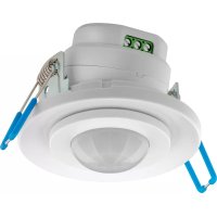
White ceiling-mounted LED fixture with green indicator lights and blue handle (no text or symbols visible)
BETRIEBSANLEITUNG ....3 USER MANUAL....13 MODE D'EMPLOI ....23 ISTRUZIONI PER L'USO ....33
BETRIEBSANLEITUNG
Inhalt
1 Sicherheitshinweise .... 4
text_image
Diagram illustrating three scenarios of lighting and ventilation in a room with lighting fixtures, lighting equipment, and air filters.Fig.3: Montageort
natural_image
Diagram showing a mechanical device before and after assembly, with no visible text or symbolsFig.4: Montage
7 Einstellungen
natural_image
Technical diagram showing a mechanical assembly before and after transformation, with no visible text or symbols.text_image
120° 360° 2.4m 5m 5m 36° Macón MacónTab.2: Reichweite
1 Safety instructions.... 12
1.1 In general.... 12
1.2 Warning levels....12
2 Description and Function 13
2.1 Product 13
2.2 Product parts....13
2.3 Scope of Delivery....13
2.4 General specifications .... 13
3 Intended Use 14
4 Preparation 14
5 Installation 14
5 Mounting 15
7 Settings 16
7.1 Changing settings 16
7.2 Reach 17
8 Maintenance, Care, Storage and Transport 17
9 Liability notice....17
10 Disposal Instructions.... 17
11 EU Declaration of Conformity 18
1 Safety instructions
1.1 In general
The user manual is part of the product and contains important information for correct use.
Read the user manual completely and carefully before use.
The user manual must be available for uncertainties and passing the product.
Keep this user manual.
Installation, assembly, maintenance and repair work must be carried out only by trained electrical specialists.
Risk of electric shock

Cut off power supply before any work on the product, switch off y fuses and secure against reconnection.
Assure and check the absence of voltage before any work on t h e p r o d u c t .
Do not modify product and accessories.
Do not cover the product.
Do not use in sealed environments.
Avoid stresses such as heat and cold, moisture and direct sunlight, vibration and mechanical pressure.
Motion detectors are not suitable as a component of alarm systems within the meaning of the Association of Property Insurers (VdS). They can trigger false alarms if the installation place has been chosen unfavorably.
Only use EN 60998-2-1 and EN 60998-2-2 tested terminals.
Follow local installation and building regulations.
In case of questions, defects, mechanical damage, trouble and other problems, non-recoverable by the documentation, contact your dealer or producer.
Use product, product parts and accessories only in perfect condition.
1.2 Warning levels

text_image
WARNING CAUTION NOTICEWarnings against hazards that may result in serious injuries or death in case of nonobservance.
Warnings against hazards that may result in injuries in case of non-observance.
Warnings against hazards that may result in material damage in case of non-observance.


2 Description and Function
2.1 Product
This product is an infrared motion sensor for indoors and is specified as installation material. It reacts to heat radiation (infrared radiation) of moving objects that enter the detection area of the sensor, eg. people and animals, etc. The sensor must „see“ the area which is monitored. Thermal radiation propagates in a straight line, but is stopped by glass or other solid objects.
Entering the detection area of the sensor switches the connected electrical consumer on and after a (adjustable) time off again automatically. A built-in photocell prevents working of the motion sensor during sunlight. In addition, the ambient brightness can be adjusted by a regulator.
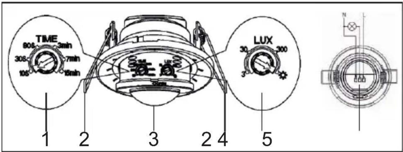
2.2 Product parts
text_image
TIME 80s 3min 30s 7min 10s 16min LUX 30 300 2 4 1 2 3 2 4 5Fig.7: Product parts
1 Switch-off delay
2 Mounting clamps
3 Motion sensor
4 Trip Sensitivity
5 Terminals
2.3 Scope of Delivery
Infra-red motion detector, User manual
2.4 General specifications
| Voltage 220-240 V~ 50 Hz | |
| Standby power ≤0.5 W | |
| Rated load | max. 800 W (incandescent lamps), max. 400 W (energy-saving lamps) |
| Detection area 8 m (<24 °C) | |
| Detection angle 360° wall/ceiling installation | |
| Switch-off delay 10±3 s ~ 15±2 Min. | |
| Brightness sensitivity | <3-2000 lx / day and night ( ⚙️) |
| Ceiling mounting height 2.2-4 m | |
| Motion detection 0.6-1.5 m/s | |
| Protection level IP20 | |
| Environment conditions -20 ~ +40 °C, 93 % RH | |
| Dimensions 61.4 x ∅80 mm | |
| Borehole diameter ∅68-70 mm | |
| Weight 94 g | |
| Switch Relais | |
| Minimum load 1 W (incandescent and LED/Energy saving lamps) | |
Tab.3: Specifications
3 Intended Use
IP20 We do not permit using the device in other ways like described in chapter "Description and Function" and „Safety Instructions". This product is protected against medium sized foreign objects, but not against water ingress. Not attending to these regulations and safety instructions might cause fatal accidents, injuries, and damages to persons and property.
4 Preparation
• Compare the specifications of all used devices to ensure compatibility.
• Check the scope of delivery for completeness and integrity.
5 Installation

Risk of electric shock
- Let open cable ends ONLY assemble by experienced electrician.
• Cut off power supply before any work on the product, switch off safety fuse and secure against reconnection.
• Assure and check the absence of voltage before any work on the product.



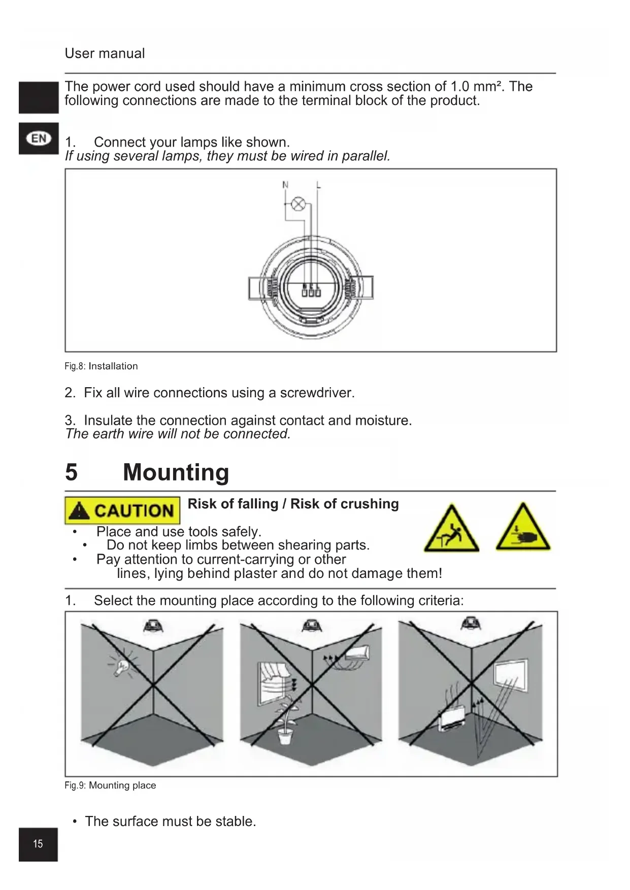
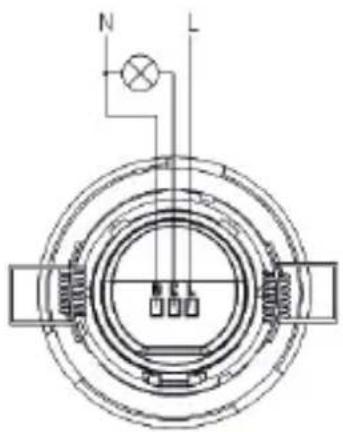
The power cord used should have a minimum cross section of 1.0 mm^2 . The following connections are made to the terminal block of the product.
- Connect your lamps like shown. If using several lamps, they must be wired in parallel.
text_image
N LFig.8: Installation
- Fix all wire connections using a screwdriver.
- Insulate the connection against contact and moisture. The earth wire will not be connected.
5 Mounting

CAUTION
Risk of falling / Risk of crushing
• Place and use tools safely.
• Do not keep limbs between shearing parts.
• Pay attention to current-carrying or other lines, lying behind plaster and do not damage them!

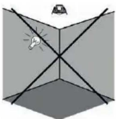
- Select the mounting place according to the following criteria:
natural_image
Diagram showing a light bulb inside a 3D cube with diagonal lines, no text or symbols present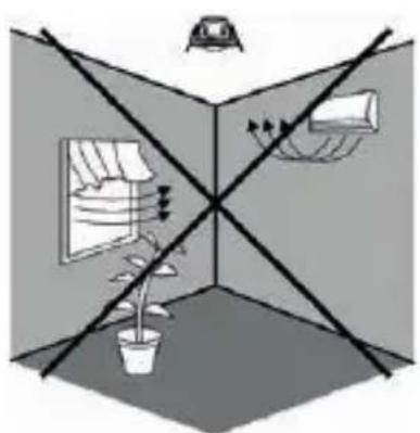
natural_image
Diagram showing a room with a window, a potted plant, and a wall-mounted shelf (no text or symbols)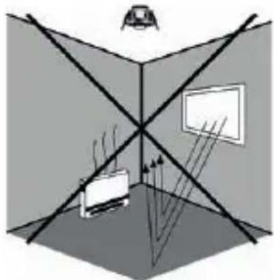
natural_image
Diagram showing two monitors in a 3D room with diagonal lines and a ceiling-mounted device (no text or symbols)Fig.9: Mounting place
• The surface must be stable.
• The product must be attached absolutely straight.
• Plants, street lighting, reflective surfaces or randomly moving objects must not be located in the detection range.
• The recommended mounting height is 2.2-4 m.
2. Drill a hole in size of the housing of the motion sensor into the wall or ceiling with suitable tools.
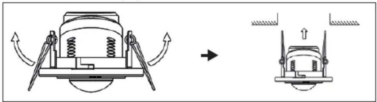
3. Press the mounting clamps up or backwards to each other and put the motion sensor into the prepared hole.
natural_image
Diagram showing a mechanical device before and after assembly, with no visible text or symbolsFig.10: Mounting
7 Settings
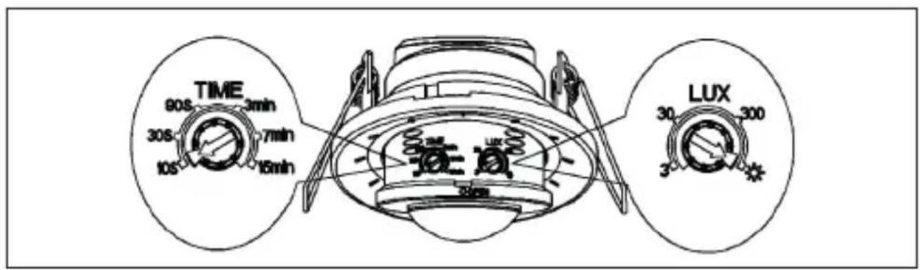
7.1 Changing settings
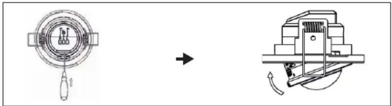
- Tilt the inner part of the motion sensor on the nut by using a screwdriver.
natural_image
Mechanical assembly diagram showing a piston-cranked mechanism transforming into a motor-like device with rotation arrow (no text or labels)Fig.12: Changing settings
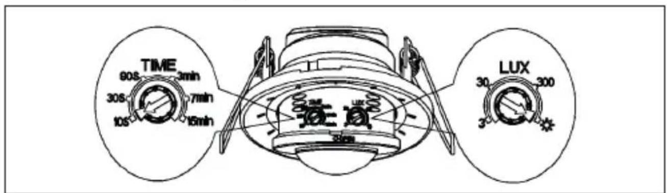
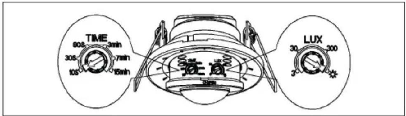
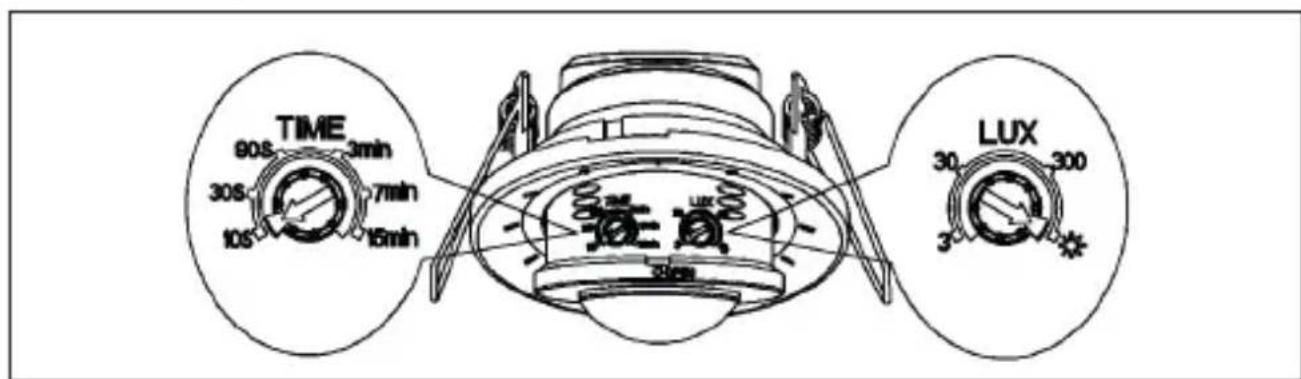
- Adjust the switch-off delay TIME by using a screwdriver between 10 seconds and 15 minutes.


- Adjust the preferred brightness sensitivity LUX by using a screwdriver. The lighting intensity in LUX is the response limit, the motion detector triggers below. If this trigger only should work at night, it must be set to 3 LUX. If the motion sensor should trigger at night and day, set it to the sun symbol. The trigger sensitivity settings for twilight, etc. are indeed after installation and must be tested depending on demand.
7.2 Reach
text_image
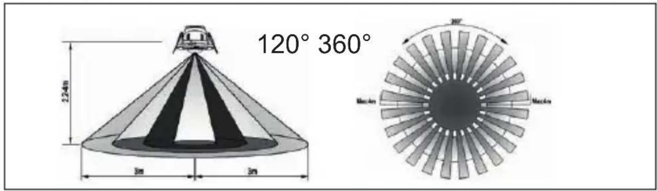
120° 360° 224m 3m 3m 3W Macin MacinTab.4: Reach
8 Maintenance, Care, Storage and Transport
The product is maintenance-free.
NOTICE
Material Damage
• Only use a dry and soft cloth for cleaning.
• Do not use detergents or chemicals.
• Store cool and dry.
- Store the product out the reach of children and in a dry and dust-protected ambience when not in use.
- Keep and use the original packaging for transport.
9 Liability notice
8 We reserve the right to printing errors and changes to product, packaging or product documentation.
• See our terms of warranty. These are available in their current form under the given contact details.
10 Disposal Instructions
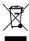
According to the European WEEE directive, electrical and electronic equipment must not be disposed with consumers waste. Its components must be recycled or disposed apart from each other. Otherwise contaminative and hazardous substances can pollute our onment.
As a consumer, you are committed by law to dispose electrical and electronic devices to the producer, the dealer, or public collecting points at the end of the devices lifetime for free. Particulars are regulated in national right. The symbol on the product, in the user's manual, or at the packaging alludes to these terms. With this kind of waste separation, application, and waste disposal of used devices you achieve an important share to environmental protection.
WEEE No: 82898622
11 EU Declaration of Conformity
CE With the CE sign Goobay ^® , a registered trademark of the Wentronic GmbH ensures, that the product is conformed to the basic standards and directives.


BETRIEBSANLEITUNG ....3 USER MANUAL....13 MODE D'EMPLOI ....23 ISTRUZIONI PER L'USO....33
MODE D'EMPLOI
Contenu
Fig.14: Installation
text_image
Diagram illustrating three scenarios of lighting and ventilation in a room with lighting fixtures, lighting equipment, and air filters.Fig.15: Place de montage
natural_image
Diagram showing a mechanical device before and after assembly, with no visible text or symbolsFig.16: Montage
7 Réglages
natural_image
Technical diagram showing a mechanical assembly before and after transformation, with no visible text or symbols.text_image
Two yellow warning signs: one showing a broken object and the other a falling person.text_image
Diagram illustrating three scenarios of lighting and ventilation in a room with lighting fixtures, showing light source, window, potted plant, and screen placement.natural_image
Diagram showing a mechanical device before and after assembly, with no visible text or symbolsFig.22: Montaggio
7 Impostazioni
natural_image
Technical diagram showing a mechanical assembly before and after transformation, with no visible text or symbols.(0.14 € / minute from German landline)
© by Wentronic Deutschland
Hotline: +49 (0180) 5005882