
AGB 645/WP - INSTRUCTION FOR USE - Cooker WHIRLPOOL - Free user manual and instructions
Find the device manual for free AGB 645/WP - INSTRUCTION FOR USE WHIRLPOOL in PDF.
| Product type | Built-in or freestanding cooker |
| Brand | Whirlpool |
| Model | AGB 645/WP |
| Power supply | 400 V three-phase / 230 V single-phase (depending on version) |
| Total power | Approximately 6-8 kW (to be confirmed on rating plate) |
| Dimensions (W x D x H) | Approximately 90 x 60 x 85 cm (standard size) |
| Weight | Approximately 50-70 kg |
| Cooking type | Electric (ceramic hob or induction) |
| Number of burners | 4 (estimated) |
| Oven type | Electric, fan-assisted or static |
| Oven capacity | Approximately 60-70 liters |
| Maximum oven temperature | 250°C |
| Special functions | Grill, bottom heat, fan-assisted, defrosting |
| Safety | Oven door lock, automatic shut-off, thermal protection |
| Cleaning | Manual cleaning with damp cloth and non-abrasive detergent |
| Electrical connection | Cable H07RN-F, cross-section adapted to power |
| Water connection | Not applicable (electric cooker) |
| Repairability index | Not provided (spare parts available through approved service) |
Frequently Asked Questions - AGB 645/WP - INSTRUCTION FOR USE WHIRLPOOL
User questions about AGB 645/WP - INSTRUCTION FOR USE WHIRLPOOL
0 question about this device. Answer the ones you know or ask your own.
Ask a new question about this device
Download the instructions for your Cooker in PDF format for free! Find your manual AGB 645/WP - INSTRUCTION FOR USE - WHIRLPOOL and take your electronic device back in hand. On this page are published all the documents necessary for the use of your device. AGB 645/WP - INSTRUCTION FOR USE by WHIRLPOOL.
USER MANUAL AGB 645/WP - INSTRUCTION FOR USE WHIRLPOOL
| I | LAVASTOVIGLIE INDUSTRIALI |
| F | LAVE-VAISELLE INDUSTRILES |
| GB | INDUSTRIAL DISHWASHER |
| D | INDUSTRIEGESCHIRRSPÜLER |
| ES | LAVAVJILLAS INDUSTRIALS |
| PT | LOICA INDUSTRIAS |
AGB 641/WP
AGB 642/WP
AGB 643/WP
AGB 782/WP
AGB 783/WP
AGB 784/WP
AGB 785/WP
AGB 644/WP
AGB 645/WP
AGB 646/WP
AGB 647/WP

MANUAL FOR USE AND INSTALLATION
MAINTENANCE AND CLEANING
Ordinary daily cleaning operations 28
Daily, routine cleaning operations appliances
with discharge pump 28
IF THE APPLIANCE IS NOT USED FOR LONG
PERIODS 28
Wash and rinse locking nuts
Overflow pipe
Resistance
Polisher compartment
Door safety micro switch
Rotating rinse arm
Rinse jet
Filter ring nut
Salt Container
Pump filter
DEUTSCH
Lower rinse arm
Spinner
Overflow
Resistance
Salt Container
Polisher compartment
Door safety micro switch
Wash jets
Rinse jets
Filter ring nut
Wash column
Pump filter
PORTUGUES
Haste de enxaguadura
Carrocel
Tubo de nivel max. da agua
Resistencia
Depóstosito sal
Recipient do abrilhantador
Segurarca micro porta
Jacto de lavagem
Jacto de enxaguadura
Aro do filtrlo
Columna de lavagem
Filtro bomba
ISTRUZIONI PER L'INSTALLATORE
DOSEUR DE PRODUIT RELUISANT
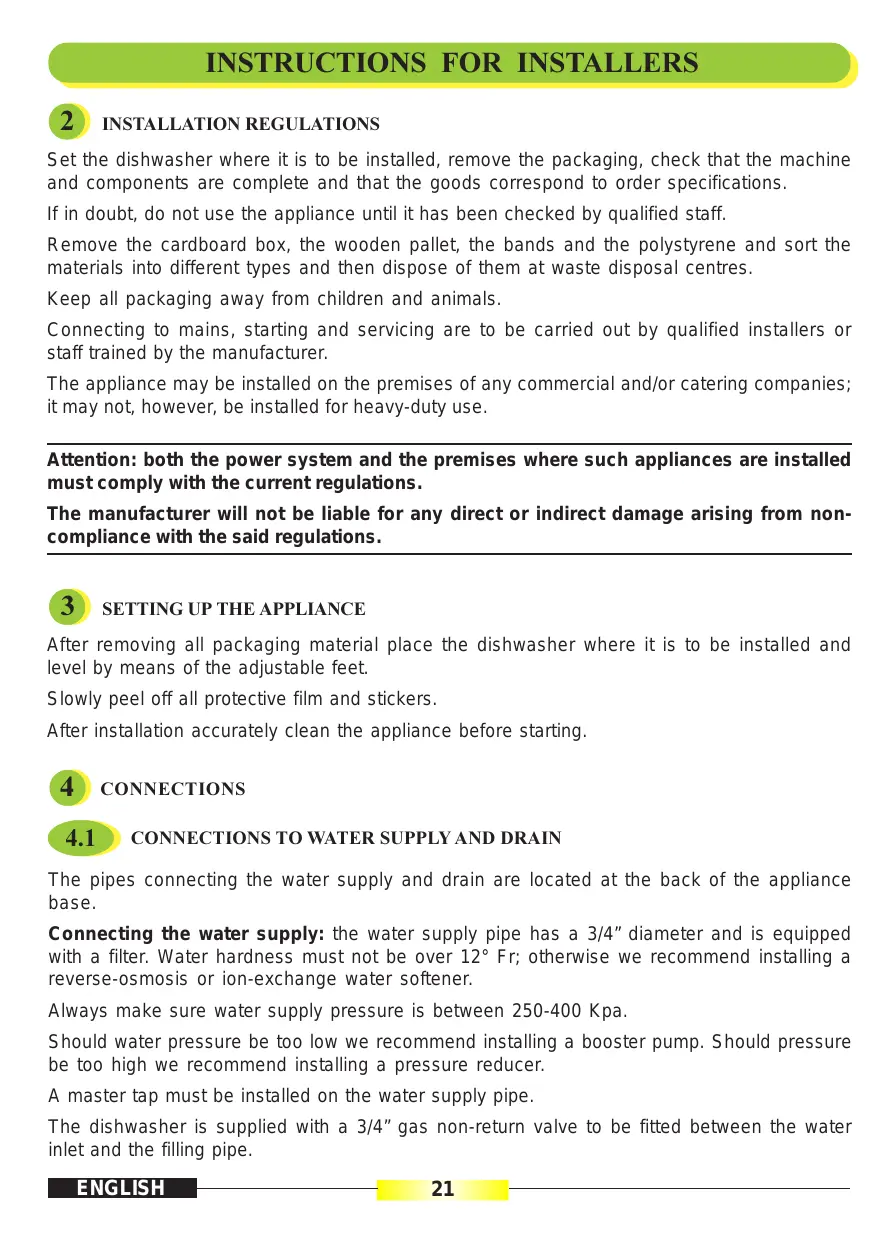
Set the dishwasher where it is to be installed, remove the packaging, check that the machine and components are complete and that the goods correspond to order specifications.
If in doubt, do not use the appliance until it has been checked by qualified staff.
Remove the cardboard box, the wooden pallet, the bands and the polystyrene and sort the materials into different types and then dispose of them at waste disposal centres.
Keep all packaging away from children and animals.
Connecting to mains, starting and servicing are to be carried out by qualified installers or staff trained by the manufacturer.
The appliance may be installed on the premises of any commercial and/or catering companies; it may not, however, be installed for heavy-duty use.
Attention: both the power system and the premises where such appliances are installed must comply with the current regulations.
The manufacturer will not be liable for any direct or indirect damage arising from noncompliance with the said regulations.
3 SETTING UP THE APPLIANCE
After removing all packaging material place the dishwasher where it is to be installed and level by means of the adjustable feet.
Slowly peel off all protective film and stickers.
After installation accurately clean the appliance before starting.
4 CONNECTIONS
4.1 CONNECTIONS TO WATER SUPPLY AND DRAIN
The pipes connecting the water supply and drain are located at the back of the appliance base.
Connecting the water supply: the water supply pipe has a 3/4 diameter and is equipped with a filter. Water hardness must not be over 12^ Fr; otherwise we recommend installing a reverse-osmosis or ion-exchange water softener.
Always make sure water supply pressure is between 250-400 Kpa.
Should water pressure be too low we recommend installing a booster pump. Should pressure be too high we recommend installing a pressure reducer.
A master tap must be installed on the water supply pipe.
The dishwasher is supplied with a 3/4 gas non-return valve to be fitted between the water inlet and the filling pipe.
Attention: in order to reach best performance and output rates all appliances must be supplied with hot water 50^ . If the machine is supplied with cold water, the production capacity of the appliance is reduced in relation to the temperature itself.
Drain: all appliances are equipped with a pipe for connection to a drain trap in the floor.
Attention: check that there are no bends or constrictions along the entire lengths of the filling and discharge pipes.
4.2 ELECTRICAL CONNECTION
The appliance is to be connected to a wall master switch of suitable power, provided with a thermal release and the relevant switch unit. Three-phase models must be provided with a power cable of suitable ength, H07RN-F type.
Attention: the grounding system is to be connected in full compliance with the current regulations. Moreover, the appliance is to be set within an equipotential system by connecting the screw located on the base and marked by the relevant sign. The Manufacturer will not be liable for any direct or indirect damage arising from noncompliance with the said regulations.
Before wiring the appliance assure that:
- the operating voltage rate corresponds to the rate shown on the appliance rating plate;
- wiring is carried out in accordance with wiring diagram.
5 FINAL SETUP OPERATIONS
- Turn water supply tap on and switch the wall master switch on.
- Make sure that there are no foreign bodies inside the dishwasher.
- Check that all the covering panels are fitted.
- Check that the overflow pipe is correctly positioned and secured.
- Make sure that the filter and the ring nut are firmly and correctly set in place.
- Make sure that the door is closed.
- Move the main switch 1 to the 1 position.
The power pilot light 2 will come on and at the same time the boiler and the tank will start to fill and the heating resistances will come on.
- When the machine has reached a temperature of 50^ in the tank and 85^ in the boiler (light 11 off), add non-foaming liquid detergent to the tank: about 50 cl. for the first load and then about 25 cl. every 4/5 washes. In any case, follow the instructions for the dosage recommendations provided by the manufacturer of the products.
6
POLISHING LIQUID DISPENSER
All models are equipped with an automatic polishing diaphragm dispenser.
As supplied, dispensers are tested at the highest capacity so as to be later adjusted according to the polisher type being used.
Adjustments are carried out by means of screw P (Fig. 3), which may be rotated anticlockwise to increase the capacity and clockwise to decrease the capacity.
The exact quantity of polishing liquid required for each rinse cycle is automatically released.
Adjustments should be carried out by detergent suppliers.
7
SAFETY DEVICE
1) Door microswitch to stop the cycle when the door is opened; close the door to restart.
2) Thermoamperometric protection on washing pump.
3) Level control on both boiler and tank.
4) Device preventing boiler water from flowing back into the mains.
5) Overflow device connected to the drain to keep tank water level constant.
6) Safety thermostat on the boiler to stop the power in case of overheating so as to prevent possible damage.
Should the safety thermostat come into action:
- remove the appliance bottom panel;
- let the boiler cool down;
- make sure the boiler thermostat is working correctly; replace if necessary;
- check the boiler heating electromagnetic switch and replace if necessary (only for three-phase 400V mod.);
- start the appliance again by pressing button R on the safety thermostat (Fig. 4).
8
SAFETY INSTRUCTIONS AND USER TRAINING
The skilled staff in charge with installation and wiring operations will also suitably train users to use the appliance correctly.
Users should be made familiar with any safety instructions to be complied with.
The instruction handbook should be kept by users for further reference.
This appliance is only designed for professional use.
The manufacturer wil not be liable for any damage arising from tampering the safety devices.
STRUCTION FOR USERS
The appliance is only designed for the professional washing of small plates, glasses and cutlery.
The manufacturer will not be liable for any direct or indirect damage arising from incorrect use of the appliance or use of products other than the said ones.

CHECKINGS BEFORE USE
Before powering the machine make sure:
- tank protection filters are clean and correctly positioned;
- the overflow device is located in the relevant position;
- wash and rinse blades are clean and freely moving;
- the wall master switch is on;
- the water tap is on;
- the washing and rinsing arms are free of impurities and are at the right angle.

FILLING THE TANK AND START-UP
When the door is closed, move the main switch 1 to the 1 position: the power pilot light 2 will come on and at the same time the boiler and the tank will start to fill.

STARTING
Wait until the machine has reached the right temperature (light 11 off), carry out one empty cycle then place the basket in the dishwasher having removed leftovers and scraps from the dishes.
Pour non-foaming washing liquid in the correct quantity as recommended by the Manufacturer.
Close the door, press button 3 to start the wash cycle, at the same time pilot light 4 will come on.
When the rinsing cycle has finished (light 4 off), open the door, remove the basket and leave it for a few minutes in the air to help dry the dishes.
If the door is opened during a programme, the programme will stop and will only start again when the door has been closed.
When washing particularly dirty dishes, the water in the tank must be changed frequently.
To achieve rinsing at the ideal temperature, pilot light 11 must always be off.
11.1
Warning: the regeneration cycle must be carried out at the end of the day or during rest periods.
To carry out the regeneration cycle proceed as described below: move the general switch 1 located on the control panel to position "0".
Remove the power plug from the mains socket.
Remove the overflow pipe (Pag. 3 - Pos. 3).
Fill the salt container located in the tank with 1Kg of coarse cooking salt, making sure that the cap is replaced securely (Fig. 7).
Fit the power plug into the mains socket.
Press the regeneration button 5, at the same time the pilot light 6 will come on.
When the regeneration cycle has been completed (20 minutes), pilot light 6 will go out.
Open the door again and refit the overflow pipe then follow the start-up - initial load instructions.
Check and top up the salt after every 5 regeneration cycles.
Before carrying out any maintenance operation, consult the chapter "Safety regulations". Cut off the electric power to the dishwasher using the general switch 1 located on the control panel and then remove the plug from the mains socket.
11.2 MODELS WITH DISCHARGE PUMP
The machine automatically discharges the water and keeps the level of the same constant inside.
To empty the tank completely, move the general switch 1 located on the control panel to "0". Press button 9 as shown in the figure; wait until the tank has been completely emptied.
12 MANUAL TANK DRAIN
After completing the wash cycle proceed as follows:
- set the master switch to "OFF";
- disconnect the wall master switch;
- turn water supply pipe off;
- remove overflow H (to allow the appliance tostart draining) (Fig. 10);
- remove filter G on draining completion (Fig. 10);
- wash the tank interior and filters with suitable products;
- place filter and the overflow back to the relevant positions.
13
PERIODICALLY
Make sure water hardness is not over 15^ Fr (150 ppm).
Make sure water temperature and pressure rates are correct; a pressure rate of over 400 Kpa might damage appliance components.
Remove any deposits from nozzles and blades.
Remove the 1 washing and 7 rinsing propellors by undoing the lock nut 2 (Fig. 1 - Pag. 3).
Clean the wash rotors and rinse under a jet of clean water.
Clean all the jets both washing and rinsing using a jet of clean water.
When cleaning the jets do not use tools which could damage the jet(s) orifice.
Replace all parts with care checking that all are positioned in their original position.
Clean the exterior of the machine with a damp cloth.
13.1 GLASS WASHING
Place glasses upside down inside the relevant container, (Fig. 5-8).
13.2 CUTLERY WASHING
Cutlery must be placed loose inside the special holders.
We recommend using the relevant partitions to wash cutlery vertically. For washing, place cutlery upright as shown, (Fig. 9).
13.3 WASHING LIQUID
Daily add non-foaming washing liquid after tank water has reached the required washing temperature.
The washing liquid should be used in the recommended quantity and added every 4 or 5 wash cycles.
The most suitable proportion for best performance may be found during use.
13.4 POLISHING LIQUID
Periodically check the level of rinse surfactant.
Dilute with water if it is too dense.
See instructions at chapter 6, for possible proportion variations of the polishing liquid.
14 FAULT CONDITION
Do not move or start the machine, but turn off the mains isolator, close the water entry tap and advise the technical service department or other specialized personnel.
| PROBLEM | CAUSE | SOLUTION |
| LINE INDICATOR LAMP DOES NOT LIGHT | Bulb burnt. Line voltage lacking. | Replace. Check supply switch or wall socket. |
| ON STARTING NO WATER SUPPLY | Water tap closed. Water trap dirty. Pressure switch defective. Solenoid coil burnt. Membrane broken or defective. | Open tap. Clean. Replace. Replace. Replace. |
| WASHING DOES NOT FUNCTION | Door micro shorting. Pushbutton defective. Timer defective. | Replace. Replace. Replace. |
| THE DRUM RINSING WATER DOES NOT HEAT UP OR THE TEMPERATURE IS INSUFFICIENT | Feed water temperature. Heater burnt. Thermostat shorting. Switch jammed. Heater covered with chalk deposit. Boiler coverd with chalk deposit. | Check. Replace. Replace. Replace. Clean. Clean. |
| WATER FILLING DOES NOT STOP | Solenoid valve coil burnt. Membrane broken or defective. Air trap dirty. Pressure switch broken or shorting. Pressure switch tube disconnected. | Replace. Replace. Replace. Replace. Re-connect. |
| THE WASH IS INSUFFICIENT | Nozzles blocked. Water temperature too low. Insufficient detergent. Detergent not suitable. Detergent badly dosed. Pumps not working. | Clean. Check. Ask for intervention. By detergent technician. Replace. |
| INSUFFICIENT RINSING | Nozzles blocked. Solenoid valve dirty. Water supply pressure not correct. Boiler covered by chalk deposit. | Clean. Clean. Check water circuit. Clean. |
| STAINS AND MARKS ON GLASSES AND CUTLERY | Water with chalk minerals and magnesium with values not within 7/10 degrees F. Water with other minerals (Fe-etc.) | Check and ask for the intervention of a specialist technician. |
The appliance has been built in such a way that it requires little maintenance. Nonetheless, it is advisable to have it checked twice a year by a qualified technician.
N.B.: the manufacturer declines all responsibility for damage caused deliberately or due to carelessness or negligence or as a result of failure to comply with the regulations, instructions or standards or due to incorrect connections.

ORDINARY DAILY CLEANING OPERATIONS
The appliance is designed so that it is protected against jets of water.
However, jets of water should not, under any circumstance, be directed against the appliance for cleaning purposes.
Before carrying out the cleaning operations, always turn off the wall-mounted switch and close the water supply tap.
Then carry out the following operations:
- empty the tank, rinse thoroughly and clean any residue material in the filter;
- replace the overflow and the filters, making sure that they are positioned correctly;
- clean any limescale before it builds up into thicker layers;
- if possible, leave the door open when the appliance is not in use;
- clean the surfaces carefully and often using a damp cloth and water and soap or common detergents as long as they do not contain abrasives or substances with a chlorine base such as sodium hypochlorite (bleach), hydrochloric acid, or other solutions: these products corrode the stainless steel irreversibly in a short time.
To clean the floor under the appliance or around it, do not use the products referred to above to prevent vapours or any droplets from producing similarly destructive effects on the steel. Rub the surfaces only in the direction of the silking. Then rinse thoroughly with clean water and dry carefully.

DAILY, ROUTINE CLEANING OPERATIONS APPLIANCES WITH DISCHARGE PUMP
Unscrew the ring nut and remove the filter taking care to clean it thoroughly (Fig. 10).
Clean the wash tank removing any deposits that might have accumulated on the bottom and rinse with clean water. Refit the filter and the ring nut leaving the door open to prevent any build-up of unpleasant smells. Remove the filter from the discharge pump and clean it thoroughly before refitting it with care (Fig. 6).

IF THE APPLIANCE IS NOT USED FOR LONG PERIODS
If the appliance is not used for some time, disconnect the main switch, turn off the water supply tap, empty the boiler completely as a preventive measure just in case excessive temperatures are reached, clean the appliance thoroughly and cover it with a cloth to protect it from dust.
- MAINTENANCE AND CLEANING
- DEUTSCH
- PORTUGUES
- ISTRUZIONI PER L'INSTALLATORE
- DOSEUR DE PRODUIT RELUISANT
- SETTING UP THE APPLIANCE
- CONNECTIONS
- CONNECTIONS TO WATER SUPPLY AND DRAIN
- ELECTRICAL CONNECTION
- FINAL SETUP OPERATIONS
- 6
- POLISHING LIQUID DISPENSER
- 7
- SAFETY DEVICE
- 8
- SAFETY INSTRUCTIONS AND USER TRAINING
- STRUCTION FOR USERS
- CHECKINGS BEFORE USE
- FILLING THE TANK AND START-UP
- STARTING
- 11.1
- MODELS WITH DISCHARGE PUMP
- MANUAL TANK DRAIN
- 13
- PERIODICALLY
- GLASS WASHING
- CUTLERY WASHING
- WASHING LIQUID
- POLISHING LIQUID
- FAULT CONDITION
- ORDINARY DAILY CLEANING OPERATIONS
- DAILY, ROUTINE CLEANING OPERATIONS APPLIANCES WITH DISCHARGE PUMP
- IF THE APPLIANCE IS NOT USED FOR LONG PERIODS
Brand : WHIRLPOOL
Model : AGB 645/WP - INSTRUCTION FOR USE
Category : Cooker