610630 - Thermostat CONRAD - Free user manual and instructions
Find the device manual for free 610630 CONRAD in PDF.


User questions about 610630 CONRAD
0 question about this device. Answer the ones you know or ask your own.
Ask a new question about this device
Download the instructions for your Thermostat in PDF format for free! Find your manual 610630 - CONRAD and take your electronic device back in hand. On this page are published all the documents necessary for the use of your device. 610630 by CONRAD.
USER MANUAL 610630 CONRAD
GB Room Thermostat with Week Program
Page 27 - 51
www.business.conrad.at
text_image
2 3 4 5 6 1 7 8 9 10 Model 15-101 Fattay max: 92.5/200 fps 6x 14kW/mHz loading Maxused temperature reading: 2°C to -8°C convection 3.6°C Temperature readings range: A C B DC (infty/decade) - Power Supply: 2 x 40 L/FAC Refrigerator/Aluminum Distillated by Coiled Electronicb) Display
text_image
SUN MON TUE WEI THU FRI SAT AM 28:88 188.8°C PM CL HT DLY 1° 2° PROG :8 E A B C D F G H 0 6 12 18 24text_image
230V-50Hz 6Amp O N M O C C NSUN = Sonntag
MON = Montag
TUE = Dienstag
WED = Mittwoch
THU = Donnerstag
FRI = Freitag
SAT = Samstag
- Introduction ...... 28
- Intended Use 29
- Scope of Delivery 29
- Explanation of Symbols 29
- Safety Information 30
a) General Information 30
b) Assembly & Operation 31
- Notes on Batteries and Rechargeable Batteries 32
- Control Elements and Connections ...... 33
a) Front and Back 33
b) Display 34
- Assembly Preparations ...... 35
- Assembly 36
- Inserting/Replacing Batteries 38
- Operation 39
a) Setting the Weekday 39
b) Setting the Time 39
c) Selectting the Heating or Cooling Mode 39
d) Setting the Temperatures 40
e) Manual Change of Operating Mode 41
f) Selecting or Setting Switching Programme 42
g) Frost Protection Function 45
h) Setting the Hysteresis 46
i) Activating/Deactivating the Switch-on Delay 46
j) Resetting to Basic Setting (Reset) 47
- Maintenance and Cleaning 48
- Disposal 48
a) General Information 48
b) Batteries and Rechargeable Batteries 48
-
Technical Data 49
-
Brief Instructions .... 50
1. Introduction
Dear Customer,
Thank you for purchasing this product.
This product complies with the statutory national and European requirements.
To maintain this status and to ensure safe operation, you as the user must observe these operating instructions!

These operating instructions are part of this product. They contain important notes on commissioning and handling. Also consider this if you pass on the product to any third party.
Therefore, retain these operating instructions for reference!
All company names and product names are trademarks of their respective owners. All rights reserved.
If there are any technical questions, contact:
Germany: Tel. no.: +49 9604 / 40 88 80
Fax. no.: +49 9604 / 40 88 48
E-mail: tkb@conrad.de
Mon. to Thur. 8.00am to 4.30pm, Fri. 8.00am to 2.00pm
2. Intended Use
The product measures the current room temperature via an internal temperature sensor. Depending on an intended target temperature, the integrated potential-free relay is activated (for contact resistance, see chapter 14). The heating and cooling devices can be controlled by it.
The product is supplied with power by two AA/mignon type batteries.
Observe the safety information and all other information in these operating instructions.
3. Scope of Delivery
- Room thermostat
- Mounting material (screws, dowels)
- Drilling template
- Operating instructions
4. Explanation of Symbols
This lightning symbol is used when your health is at risk, e.g. from electric shock.

An exclamation mark in a triangle indicates important notes in these operating instructions that must be strictly observed.

The “hand” symbol indicates special information and advice on operation.
5. Safety Information

In case of damage caused by non-compliance with these operating instructions, the warranty/guarantee will expire. We do not assume any liability for consequential damage!
We do not assume any liability for damage to property or personal injury caused by improper use or the failure to observe the safety instructions! In such cases the warranty/guarantee will expire.
Dear Customer,
this safety information serves not only to protect the product, but also your own safety and the safety of other persons. Therefore, read this chapter very carefully before taking the product into operation!
a) General Information
Attention!
The appliance must only be connected to the mains voltage by a qualified specialist (e.g. electrician) familiar with the relevant regulations (e.g. VDE)!
Improper work, carried out on the mains voltage, endangers not only your life but also the life of others! There is danger to life from electric shock!
If you do not have the expertise required for installation, do not install the device yourself but ask a specialist.
- The unauthorized conversion and/or modification of the product is prohibited for safety and approval reasons (CE).
- The product is not a toy. Devices that are operated with mains voltage have no place in the hands of children. Therefore, be particularly careful when children are present.
- Do not leave packaging material unattended. It may become a dangerous toy for children.
- At industrial sites, the accident prevention regulations of the association of the industrial workers' societies for electrical equipment and utilities must be followed!
- Handle the product with care; impacts, shock or fall even from low heights will damage it.
b) Assembly & Operation
- The product should only be used in closed, dry indoor areas; it must not become damp or wet! There is the risk of a potentially fatal electric shock!
• The product may be operated stationarily installed. - Operation of the product with two batteries or rechargeable batteries type AA/mignon is permissible; do not use any other voltage/power supply.
- The switching output on the rear is potential-free (NC and NO contact). It can also be used to directly control power supply for a heating or cooling device. If work is required on the mains voltage, it must only be performed by a trained specialist (e.g. electrician). There is danger to life from electric shock!
Observe the information in Chapter "Technical Data" for maximum contact load capacity.
- Do not install or operate the product inside of rooms or in bad ambient conditions where flammable gases, vapours or explosive dust may be or are present! There is a danger of explosion!
- The product must not be exposed to extreme temperatures, strong vibration or strong mechanical strain.
- If it can be assumed that safe operation is no longer possible, the device must be turned off and precautions are to be taken to ensure that it is not used unintentionally. Then have the product inspected by a specialist.
It can be assumed that safe operation is no longer possible if:
- the product is visibly damaged
- the product does not work or not work properly (smoke or burnt smell, audible crackling, discolouration of the product or adjacent surfaces)
- the product was stored under unfavourable conditions for an extended period of time
- if it was subjected to heavy stress during transport
- Should questions arise that are not answered by these operating instructions, contact us (for contact information, see chapter 1) or another expert.
6. Notes on Batteries and Rechargeable Batteries
- Keep batteries/rechargeable batteries out of the reach of children.
- Ensure that the polarity is correct when inserting the batteries/rechargeable batteries (observe plus/+ and minus/-).
- Do not leave any batteries/rechargeable batteries lying around openly. There is a risk of batteries being swallowed by children or pets. If swallowed, consult a doctor immediately.
- Leaking or damaged batteries/rechargeable batteries can cause chemical burns to skin at contact; therefore, use suitable protective gloves.
- Batteries/rechargeable batteries must not be short-circuited, disassembled or thrown into fire. There is a danger of explosion!
- Do not recharge normal batteries. Danger of explosion! Only charge rechargeable batteries which are intended for this purpose; use a suitable battery charger.
- Never mix batteries and rechargeable batteries.
- Do not mix batteries/rechargeable batteries with different condition (e.g. fully and partially charged batteries). Always use two batteries/rechargeable batteries of the same type and manufacturer for operating the room temperature controller.

The room thermostat may also be operated with rechargeable batteries. The lower operating voltage of rechargeable batteries (batteries = 1.5 V/cell, rechargeable batteries = 1.2 V/cell), however, will lead to a much shorter operating times.
For secure, long-term operation of the product, we therefore recommend using only high-quality alkaline batteries and no rechargeable batteries.
If you still want to use rechargeable batteries, NiMH batteries with a low self-discharge should be inserted in the room temperature controller.
7. Control Elements and Connections
a) Front and Back
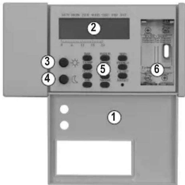
1 Folding lid for covering the keypad and battery compartment
2 LC display
3 Button “ ✪” for comfort temperature (regular temperature)
4 Button “ ℃” for savings temperature (night reduction)
5 Operating buttons
6 Battery compartment for 2 batteries type AA/mignon (figure without battery compartment lid)
7 Attachment hole 1
8 Attachment hole 2
9 Temperature sensor
10 Relay screw terminals
NC/COM/NO
(for connection to heating or cooling unit or external control)
text_image
MON MON TEE AND TBE PRI SET ① ② ③ ④ ⑤ ⑥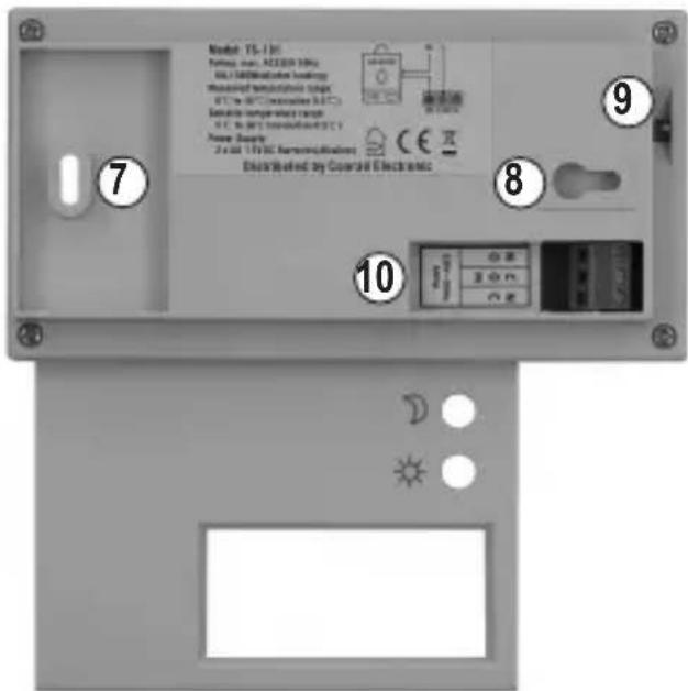
text_image
Model 15-130 Funding rate: AC/DCM 100% DCI 1300/DCI/DCI loadings Measured temperature range DCI to DCI (conventional DCI) Seawable temperature range DCI to DCI (conventional DCI) Power Supply 2 x 40 V DC Power/Displacement Disassembled by Coated Electronic 7 8 9 10b) Display
text_image
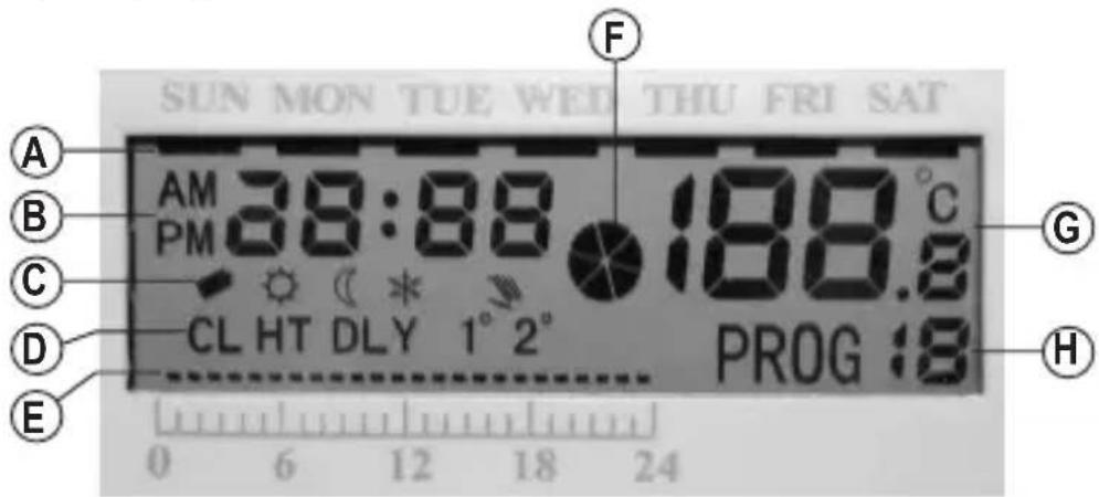
SUN MON TUE WED THU FRI SAT AM 38:88 188.8°C PM CL HT DLY 1° 2° PROG :8 A B C D E 0 6 12 18 24 F G HA Wide dashes for weekday display
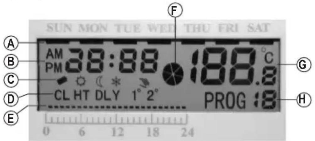
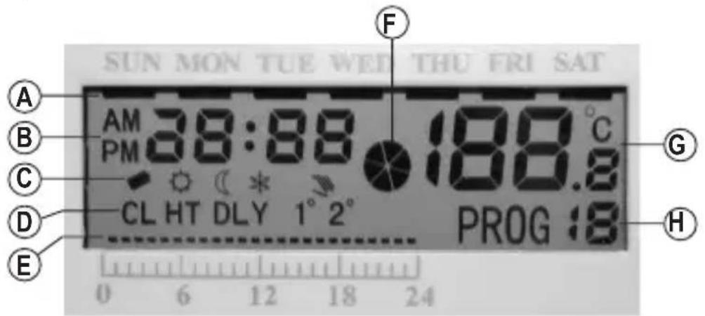
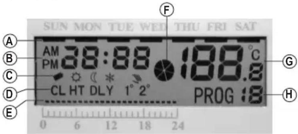
B Display area for time, switching time, etc.
C Symbols for.....
“ ” Battery weak/empty
“☀” Comfort mode (the comfort temperature set with “ ” is maintained by the thermostat)
“” Savings mode (night reduction, the savings temperature set with “” is maintained by the thermostat)
“*” Frost-protection mode (switching programme “PROG 0”, a temperature of +7 °C is maintained)
“3” Manual selection of comfort or savings temperature is activated
D Function display for....
"CL" Cooling mode
"HT" Heating mode
“DLY” Switch-on delay
“1° 2°” Hysteresis (either 1 °C or 2 °C)
E Narrow dashes for display of comfort/savings mode
F Moving figure in the form of a rotating fan shows that the relay has switched
G Display area for current room temperatures or setting of the comfort or savings temperature
H Switching programme "PROG 0......19"
8. Assembly Preparations

Observe Chapter "5. Safety Information".
The room thermostat must only be connected to the mains voltage by a qualified specialist (e.g. electrician) familiar with the relevant regulations (e.g. VDE)!
Improper work at the mains voltage endangers not only yourself, but also others!
If you do not have the expertise required for installation, do not install the device yourself but ask a specialist.
- Assembly and operation of the room temperature controller is only permissible in closed, dry indoor rooms.
- Mount the room thermostat on stable surfaces only. Use screws or dowels appropriate for the surface. The product may be operated stationarily installed.
- Keep sufficient distance to devices that produce magnetic or electrical fields at the assembly site (e.g. speaker, electric motors, etc.).
- The room thermostat may be voltage-free during installation.
Turn off the power on all poles of the mains supply by removing the respective electric circuit fuse or switching off the circuit breaker. Also switch off the respective fault-current protective switch. Protect it from unauthorized re-activation, e.g. with a danger sign.
Check that the mains supply powered down, e.g. with an appropriate meter (digital multimeter).
This applies accordingly if only low voltage is to be supplied through the switching output, since this may cause short circuit.
- Observe the maximum contact load capacity of the internal switching relay according to Chapter 14 (Technical Data) for connection.
- To ensure that the room thermostat works properly, do not mount it close to radiators, electrical devices or windows. Also avoid direct sunlight.
9. Assembly
Caution, important!
Observe Chapter "5. Safety Information" and Chapter "8. Preparation for Installation"!
- Open the casing by swivelling the folding lid (1) forwards.
- Use the included drilling template to mark the assembly positions at the wall (horizontal hole distance approx. 120 mm).
- Use suitable screws and dowels for the surface.
When drilling or tightening screws, ensure that no wires or lines are damaged!
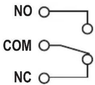
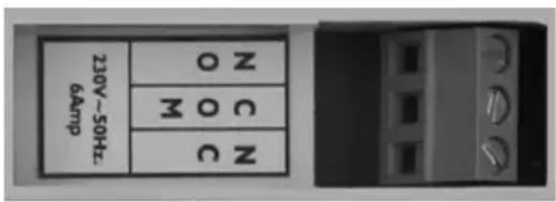
- Connect the power supply to the screw terminals (10). The relay is potential-free. Observe the maximum contact load resistance (230 V/AC, 50 Hz, 6 A, ohmic load).
flowchart
graph TD
    A["NO"] --> B[" "]
    C["COM"] --> D[" "]
    E["NC"] --> F[" "]
text_image
230V~50Hz 6Amp O N O C M C HNC Opener contact (NC = "normally closed" = The contact is closed when not activated) NO Closer contact (NO = "normally open" = The contact is open when not activated) COM Centre contact

The connection must be performed according to the desired operating mode (heating/cooling) or the external connections.
Observe the operating instructions of the device that is to be controlled by the thermostat for how to perform the connections.
Heating operation
In heating operation, the relay is switched when the temperature drops below the set value, so that the contacts "COM" and "NO" are connected. A connected heater must switch on now.
When the temperature measured via the sensor exceeds the set threshold value, the relay switches off so that the contacts "COM" and "NC" are connected. The connected heater now has to switch off.
Cooling operation
In cooling operation, the relay is switched when the temperature exceeds a set value, so that the contacts “COM” and “NO” are connected. A connected cooler must switch on now.
When the temperature measured via the sensor undercuts the set threshold value, the relay switches off so that the contacts "COM" and "NC" are connected. The connected cooler now has to switch off.
- First set the room temperature controller on the left screw with the left attachment hole (8) and push it a bit to the left.
The room temperature controller is fastened to the screw by this.
Observe that the cables connected to the terminal clamps are not crushed or damaged by sharp edges.

When the room temperature controller cannot be pushed open beyond the oblong hole of the left attachment hole (8), turn out the screw a bit.
If the room temperature controller is too loose, however, turn the screw in a bit further.
- Then screw the room temperature controller in tight through the second attachment hole (7) in the battery compartment bottom (6).
Check if the room temperature controller is attached firmly to both screws.
- Switch on the mains voltage.
- If you have not done so yet, insert two type AA/mignon batteries in the battery compartment (6) with the correct polarity; see Chapter 10.
10. Inserting/Replacing Batteries

The power supply of the room temperature controller is provided only by two batteries type AA/Mignon.
As already named in chapter 6, operation is possible with rechargeable batteries, but not recommended because of the much shorter operating duration.
- Open the casing by swivelling the folding lid (1) forwards.
- Remove the battery compartment lid; it is only connected with a clip.
- Insert two type AA/mignon batteries with correct polarity into the battery compartment (6) (observe plus/+ and minus/-), see label in the battery compartment.
- Replace the lid of the battery compartment again and close the battery compartment with it.
- If you do not want to programme (e.g. for initial commissioning), close the casing again by swivelling the flap lid up.
- A battery replacement is necessary if the contrast of the display decreases or if no indication appears on the display.
If the batteries are low, the display shows the battery symbol "→" to the left.
11. Operation
a) Setting the Weekday
Push the button "DAY" repeatedly until the black bar at the top of the display is below the desired weekday.
SUN = Sunday
MON = Monday
TUE = Tuesday
WED = Wednesday
THU = Thursday
FRI = Friday
SAT = Saturday
b) Setting the Time
- To set the hours of the time, push the button "HOUR". Keeping the button down for some time will quickly adjust the hours display.
- To set the minutes of the time, push the button "MIN". Keeping the button down for some time will quickly adjust the minutes display.
c) Selecting the Heating or Cooling Mode
- Briefly press the button "MODE" to terminate setting mode.
- Use the button “CL/HT” to select the heating and cooling mode. The display shows the current operating mode at the bottom left:
Display "HT": Heating mode (for heating operation)
Display "CL": Cooling mode (for operation of the cooling unit/climate system) - To terminate this setting mode, briefly press "OK".

The setting mode is left automatically if no button is pushed for approx. 10 seconds.
The switch-on delay is also activated in the cooling mode (cannot be switched off). Observe Chapter 11. i).
In heating mode, the savings temperature must be set lower than the comfort temperature. This must be set reversed in cooling mode (savings temperature must be higher than comfort temperature).
d) Setting the Temperatures
Two temperatures can be set to later perform the temperature monitoring of the room temperature controller and a relay switching process:
Button “❄” Comfort temperature (regular temperature value)
Button “☐” Savings temperature (temperature value for night reduction)

When the temperatures are to be set, the thermostat must not be in the programme "0" (display "PROG 0" at the lower right). You need to leave this programme before setting the above temperature values. In this respect, see chapter 11. f).
The programme “0” is the frost protection mode, the temperature is set fixed to +7 °C in this operating mode (cannot be changed).
- Briefly press the button "TEMP"; the temperature display flashes in the display.
- To set the comfort temperature, push the button “ ✪” (3) repeatedly until the display shows the desired temperature.
Keeping the button down for some time will adjust quickly.
- To set the savings temperature (night reduction), push the button “ ℈” (4) repeatedly until the display shows the desired temperature.
Keeping the button down for some time will adjust quickly.
- To terminate this setting mode, briefly press "OK". The temperature display stops flashing; the temperatures are saved.

The setting mode is left automatically if no button is pushed for approx. 10 seconds.
e) Manual Change of Operating Mode
1. Short-term change of the operating mode
- Push the button “ ✉” (3) or “ ℰ” (4) once (!) to switch from the current operating mode (comfort or savings temperature) to the respective other.
Additionally, the display shows a hand icon “☐” to show that the operating mode was manually switched (the icon is shown only in the respective other operating mode).
- Manual settings remain active until the current hour has elapsed.

Example:
Pushing the button “ ℉” (4) in the morning (comfort temperature is active) at 10:53 a.m. to select the savings temperature, the temperature will be returned to comfort temperature at 11:00 a.m. already.
2. Longer change of the operating mode for a certain time

This function can be used, e.g., if you remain awake longer in the evening and therefore want to prevent switching to savings temperature (night reduction) at a specific time.
- Push the button “☀” (3) or “℃” (4) repeatedly (!) to set the period for how long manual selection of the operating mode is to take.
You may set a period from 1 to 23 hours (step width 1 hour).
Keep the respective button pressed for quick adjustment.
To leave the setting mode, push either the button "OK" briefly or do not push any button for approx. 10 seconds.
- After passing of the set period (e.g. 3 hours), automatic operation is continued (comfort or savings temperature depending on time and switching programme).
- To return to automatic operation prematurely, check the icon just shown (“ *” or “ ”) and push the other button.

Example:
When the icon “☀” and hand icon “ ” are displayed (manual operation), push the button “☐(4).
If, however, the “” and hand icon “” are displayed (manual operation), push the button “”(3).
f) Selecting or Setting Switching Programme

If this has not happened yet, set the day of the week and time first. Choose between the heating and cooling mode and set the desired comfort and savings temperature.
The room temperature controller has 10 firmly programmed switching programmes and 10 switching programmes you can programme freely.
At the lower edge of the LC display (on the 24 h timeline printed on the casing), narrow black dashes are displayed depending on switching programme (one dash per hour).
A black dash means that the comfort temperature is kept by the thermostats in this hour.
If no dah is visible, the thermostat works with the savings temperature (night reduction).
Proceed as follows (also see process plan two pages later):
- Push the button "DAY" repeatedly until the wide black bar at the top of the display is below the desired weekday (also see chapter 11. a).
- Briefly press the button "PROG" to terminate setting mode.
- Use the button “PROG#” to select the desired switching programme. The switching programmes “PROG 0” to “PROG 9” are firmly pre-programmed and cannot be changed.
PROG 1
PROG 6 0 6 12 18 24
PROG 2
PROG 7 0 6 12 18 24
PROG 3
PROG 8
PROG 4 0 6 12 18 24
PROG 9 0 6 12 18 24
PROG 5 0 6 12 18 24
PROG 0 0 6 12 18 24

The switching programme “PROG 0” is a special frost-protection programme. The temperature is firmly set to +7 °C. The display additionally shows the snowflake icon “*”

Caution, important!
After selecting the switching programme "PROG 0" (frost protection, icon " *" and display "PROG 0" in the display), the comfort or savings temperature cannot be set (see chapter 11. d).
If you want to set the comfort or savings temperature, first select a different switching programme than "PROG 0".
- The switching programmes "PROG 10" to "PROG 19" can be freely programmed by you. Use the button "PROG#" to select, e.g. the switching programme "PROG 10".
The left dash at the 24h timeline flashes; the time "0:00" appears.
Use the buttons “☀” (3) or “℃” (4) to select the temperature value the thermostat is supposed to keep between 0:00 and 0:59 hours.
The button “☀” (3) represents the comfort temperature and the button “☐” (4) for the savings temperature (night reduction).

When pushing the button “ ”(3), a dash will appear with the respective hour; the button “ ”(4) will make the dash by the respective hour disappear.
After every push of a button, the flashing dash moves one hour to the right and the hour displayed is increased by one.
- To set the switching programme for the next weekday, push the button "PROG". At the top of the display, the wide black bar for the weekday display moves on by one day.
As described above, select the switching programme for the new weekday with the "PROG#" button (either one of the firmly pre-programmed switching programmes or one of the switching programmes freely programmed by you). - To terminate this setting mode, briefly press "OK". The current time appears again in the upper left of the display.

The setting mode is left automatically if no button is pushed for approx. 10 seconds. Programming is assumed.

Important!
The switching programme must be programmed for every weekday. The basic settings have the switching programme "PROG 1" pre-set for every weekday.
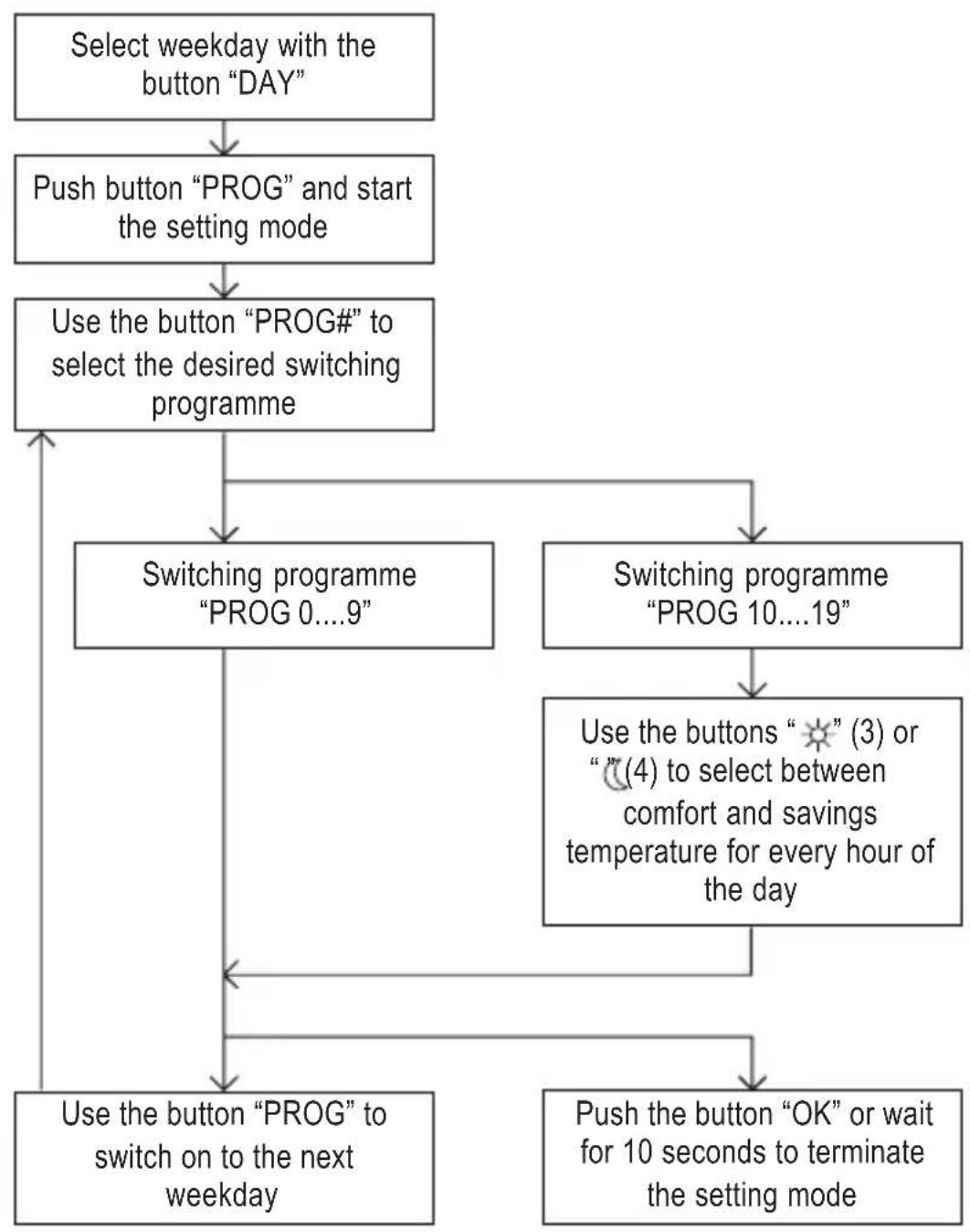
flowchart
graph TD
    A["Select weekday with the button "DAY""] --> B["Push button "PROG" and start the setting mode"]
    B --> C["Use the button "PROG#" to select the desired switching programme"]
    C --> D["Switching programme "PROG 0...9""]
    C --> E["Switching programme "PROG 10...19""]
    D --> F["Use the button "PROG" to switch on to the next weekday"]
    E --> G["Use the buttons "(3) or "(4) to select between comfort and savings temperature for every hour of the day"]
    F --> H["Push the button "OK" or wait for 10 seconds to terminate the setting mode"]
g) Frost Protection Function

The frost protection function is only available if the room temperature controller is in heating mode (see Chapter 11. c).
The room temperature controller keeps the temperature above +7 °C.
- Push the button "DAY" repeatedly until the wide black bar at the top of the display is below the desired weekday (also see chapter 11. a).
- Briefly press the button "PROG" to terminate setting mode.
- Use the button "PROG#" to select the switching programme "PROG 0". The snowflake icon "❄" appears below the time display.
- To terminate this setting mode, briefly press "OK". The current time appears again in the upper left of the display.

The setting mode is left automatically if no button is pushed for approx. 10 seconds. Programming is assumed.
Observe chapter 11. f) for selecting or setting the switching programmes.

Caution, important!
After selecting the frost protection function (icon “*” and display “PROG 0”), the comfort or savings temperature cannot be set (see chapter 11. d).
If you want to set the temperature values for the comfort or savings temperature, first select a different switching programme than "PROG 0"!
h) Setting the Hysteresis
For the thermostat not to trigger a switching process at every small temperature change, the hysteresis can be switched between 1 °C and 2 °C.

Example:
When using the heating mode and a pre-set temperature value of 20 °C , the thermostat will switch on the heating at a hysteresis of 1 °C at an ambience temperature of 19.5 °C and off at 20.5 °C .
Setting the hysteresis to 2 °C, the thermostat switches the heating on at 19 °C and off at 21 °C.
- Briefly press the button "MODE" to terminate setting mode.
- Use the button "1C/2C" to select the desired hysteresis.
Display "1°": Hysteresis set to 1 °C
Display "2°": Hysteresis set to 2 °C
- To terminate this setting mode, briefly press "OK".

The setting mode is left automatically if no button is pushed for approx. 10 seconds.
i) Activating/Deactivating the Switch-on Delay
The switch-on delay prevents connected heating and cooling devices to be switched on or off too often at quickly fluctuating temperatures.

Example:
When the switch-on delay is activated, a connected heating is only switched on after it was switched off for 5 minutes before.

In cooling more, the switch-on delay is automatically activated for the protection of the cold compressor. It cannot be switched off.
- Briefly press the button "MODE" to terminate setting mode.
- Switch the switch-on delay on with the button "DELAY" (the lower left of the display shows "DLY") or off.
- To terminate this setting mode, briefly press "OK".

The setting mode is left automatically if no button is pushed for approx. 10 seconds.
j) Resetting to Basic Setting (Reset)
Use the recessed button "RESET" to reset the thermostat to the basic settings.

All settings made by you will be lost!
The basic settings are:
Time: 0:00
Weekday: ...... Sunday
Temperature value for day operation: ..... 19 °C
Temperature value for night operation: ..... 15 °C
Switching programme: ...... Every day is set to switching programme "PROG 1"
Hysteresis: 1 °C
Switch-on delay: ...... Switched off
Mode:.... Heating mode
12. Maintenance and Cleaning
Servicing or repair must only be carried out by a specialist or specialist workshop. The product contains no parts that require servicing by you. Therefore, do not disassemble it.
To clean the outside of the room thermostat, a dry, soft and clean cloth is sufficient.

Do not press on the display too strongly; this may lead to scratches or malfunctions of the display, or even to the display breaking.
Dust on the casing can easily be removed with a clean brush and a vacuum cleaner.
Never use any aggressive cleaning agents, cleaning alcohol or other chemical solutions, since these may damage the casing or even impair function.
13. Disposal
a) General Information
Dispose of the product according to the relevant statutory regulations at the end of its service life.
b) Batteries and Rechargeable Batteries
You as the end user are required by law (Battery Ordinance) to return all used batteries/rechargeable batteries. Disposing of them in the household waste is prohibited!
Batteries and rechargeable batteries containing hazardous substances are marked with adjacent symbol to indicate that disposal in the household waste is prohibited.
The descriptions for the respective heavy metal are: Cd=cadmium, Hg=mercury, Pb=lead (the names are indicated on the battery/rechargeable battery e.g. below the rubbish bin symbol shown to the left).
You may return used batteries/rechargeable batteries free of charge at the official collection points of your community, in our stores, or wherever batteries/rechargeable batteries are sold!
You thus fulfil your statutory obligations and contribute to the protection of the environment.
14. Technical Data
Operating voltage .... 3 V/DC, 2 type AA/mignon batteries
Temperature setting range ..... +5 °C to +30 °C
Hysteresis 1 °C or 2 °C (switchable)
Switching voltage 230 V/AC, 50 Hz or 24 V/DC
Contact load resilience ...... 6 A (Ohmic load)
Type of operation .... heating or cooling mode
Frost protection function .... yes (by switching programme "PROG 0")
Switching programmes ..... 20
(10 of them pre-programmed and 10 freely programmable)
Night reduction .... yes
Dimensions (W x H x D) ...... 155 x 80 x 31 mm
Weight ..... approx. 150 g
15. Brief Instructions
Set weekday (chapter 11. a)
- Briefly push the button "DAY"
Setting the time (chapter 11. b)
- Push the button "HOUR" to set the hours, the button "MIN" to set the minutes (keep the button pushed for quick adjustment)
Select Heating or Cooling Mode (chapter 11. c)
- Briefly push the button "PROG", then the button "CL/HT" (display shows "HT" = heating mode, "CL" = cooling mode)
- To leave the setting mode, either briefly push the button "OK" or wait for 10 seconds
Setting the comfort and savings temperatures (chapter 11. d)
- Briefly push the button "TEMP"
- For setting the comfort temperature, push the button “❄” (keep it pushed for quick adjustment)
- For setting the savings temperature (=night reduction), push the button “ ℈” (keep it pushed for quick adjustment)
- To leave the setting mode, either briefly push the button "OK" or wait for 10 seconds
Manual selection of comfort or savings temperature (chapter 11. e)
- Depending on desired operating mode, briefly push the button “☀” or “∞” once; at the next full hour, automatic operation will be used again
- If you desire manual operation for an extended time (e.g. for a party), push the respective button repeatedly to set the time from 1 - 23 hours. After the end of this time, automatic operation is used again.
Select the switching programme (chapter 11. f)
- First use the button "DAY" to select the weekday, then briefly push the button "PROG".
- Select the desired switching programme with the button “PROG#” (switching programmes 0-9 are pre-programmed and cannot be changed).
For switching programme 11-19, use the button “ ✝” or “ √” for the 24 hours of the day to select comfort or savings temperatures for the respective times.
- Use the button “PROG” to switch to the next day and set the switching programme there, or the button “OK” to leave setting mode (alternatively wait for 10 seconds without pushing any button).
Use the frost protection function (chapter 11. g)
- First use the button "DAY" to select the weekday, then briefly push the button "PROG".
- Use the button "PROG#" to select the switching programme "PROG 0"
- Use the button "PROG" to switch to the next day and set the switching programme there, or the button "OK" to leave setting mode (alternatively wait for 10 seconds without pushing any button).
Setting the hysteresis (chapter 11. h)
- Briefly push the button "PROG"
- Use the button "1C/2C" to switch between 1 °C and 2 °C
- To leave the setting mode, either briefly push the button "OK" or wait for 10 seconds
Activating/deactivating the switch-on delay (chapter 11. i)
- Briefly push the button "PROG"
- Use the button "DELAY" to switch the switch-on delay ("DLY" in the display) on or off (note: The switch-on delay cannot be switched off in cooling more to protect the cooling compressor)
- To leave the setting mode, either briefly push the button "OK" or wait for 10 seconds
Reset to the basic settings (chapter 11. j)
- Briefly push the button "RESET". All settings are lost.
Page
text_image
Model 15-194 Power supply: MAXIM (10kA) MAXIM (1000V) (10kA) Maximized temperature range: 37°C to 80°C (constant 3.6°C) Maximum temperature range: 37°C to 80°C (constant 3.6°C) Power Supply: 2 x 10^4 (10kA Powered Mode) Display Rated by Covered Electronic ⑦ ⑧ ⑨ ⑩
natural_image
Simple diagram with a rectangle, two dots labeled 'D' and one star symbol, no readable text or labels.b) Écran
text_image
SUN MON TUE WEI THU FRI SAT AM 28:88 188.8°C PM CL HT DLY 1° 2° PROG :8 A B C D E 0 6 12 18 24 F G HAttention, important!
SUN = Dimanche
MON = Lundi
TUE = Mardi
WED = Mercredi
THU = Jeudi
FRI = Vendredi
SAT = Samedi
Attention, important!
Attention, important!
text_image
MON MON TEE AND TEE PRI SET ① ② ③ ④ ⑤ ⑥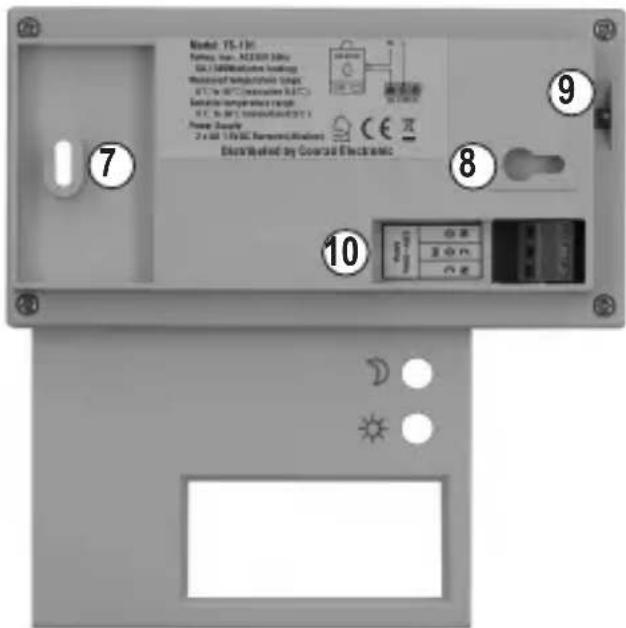
text_image
Model 15-130 Motor, fan, AC/DC/DC Motor DC / 120000000000000000000000000000000000000000000000000000000000000000000000000000000000000000000000000000 7 9 8 10 Distributed by Covered Electronicb) Display
text_image
SUN MON TUE WED THU FRI SAT AM 38:88 188.8°C PM CL HT DLY 1° 2° PROG :8 A B C D E 0 6 12 18 24 F G H“DLY” Inschakelvertraging
“1° 2°” Hysterese (1 °C of 2 °C)
© Copyright 2011 by Conrad Electronic SE.
GB Legal Notice
These operating instructions are a publication by Conrad Electronic SE, Klaus-Conrad-Str. 1, D-92240 Hirschau (www.conrad.com). All rights including translation reserved. Reproduction by any method, e.g. photocopy, microfilming, or the capture in electronic data processing systems require the prior written approval by the editor. Reprinting, also in part, is prohibited.
These operating instructions represent the technical status at the time of printing. Changes in technology and equipment reserved. © Copyright 2011 by Conrad Electronic SE.
© Copyright 2011 by Conrad Electronic SE.
NL Colofon
© Copyright 2011 by Conrad Electronic SE.
V1_1111_01